LS04EN. Conceptual Database Model. Entity Relationship ...
46
© Yuriy Shamshin 1/46 Conceptual Database Model. Entity Relationship Diagram (ERD). Contents • Conceptual, logical and physical data models • What is an ER diagram? • History of ER models • Uses of entity relationship diagrams • Mapping natural language • The components and features of an ER diagram • Entity Relationship Diagram Tutorial • Create ERD from existing database. • Different Types of Keys in DBMS • ERD symbols on several notation styles • ERD Examples Learn the essentials of ER Diagrams and ER Models, along with their origins, uses, examples, components, limitations and guidelines on how to draw them using our ER diagram tool. Conceptual, logical and physical data models ER models and data models are typically drawn at up to three levels of detail: • Conceptual data model: The highest-level view containing the least detail. Its value is showing overall scope of the model and portraying the system architecture. For a system of smaller scope, it may not be necessary to draw. Instead, start with the logical model. • Logical data model: Contains more detail than a conceptual model. More detailed operational and transactional entities are now defined. The logical model is independent of the technology in which it will be implemented. • Physical data model: One or more physical model may be developed from each logical model. The physical models must show enough technology detail to produce and implement the actual database. Sometimes, engineers will branch out ER diagrams with additional hierarchies to add necessary information levels for database design. For example, they may add groupings by extend up with superclasses and down with subclasses. It is Extended ERD.
Transcript of LS04EN. Conceptual Database Model. Entity Relationship ...
© Yuriy Shamshin 1/46
Conceptual Database Model. Entity Relationship Diagram (ERD). Contents
• Conceptual, logical and physical data models • What is an ER diagram? • History of ER models • Uses of entity relationship diagrams • Mapping natural language • The components and features of an ER diagram • Entity Relationship Diagram Tutorial • Create ERD from existing database. • Different Types of Keys in DBMS • ERD symbols on several notation styles • ERD Examples
Learn the essentials of ER Diagrams and ER Models, along with their origins, uses, examples, components, limitations and guidelines on how to draw them using our ER diagram tool.
Conceptual, logical and physical data models ER models and data models are typically drawn at up to three levels of detail:
• Conceptual data model: The highest-level view containing the least detail. Its value is showing overall scope of the model and portraying the system architecture. For a system of smaller scope, it may not be necessary to draw. Instead, start with the logical model.
• Logical data model: Contains more detail than a conceptual model. More detailed operational and transactional entities are now defined. The logical model is independent of the technology in which it will be implemented.
• Physical data model: One or more physical model may be developed from each logical model. The physical models must show enough technology detail to produce and implement the actual database.
Sometimes, engineers will branch out ER diagrams with additional hierarchies to add necessary information levels for database design. For example, they may add groupings by extend up with superclasses and down with subclasses. It is Extended ERD.

© Yuriy Shamshin 2/46
What is an ER diagram? An Entity Relationship (ER) Diagram is a type of flowchart that illustrates how “entities” such as people, objects or concepts relate to each other within a system. ER Diagrams are most often used to design or debug relational databases in the fields of software engineering, business information systems, education and research. Also known as ERDs or ER Models, they use a defined set of symbols such as rectangles, diamonds, ovals and connecting lines to depict the interconnectedness of entities, relationships and their attributes. They mirror grammatical structure, with entities as nouns and relationships as verbs.
ER diagrams are related to data structure diagrams (DSDs), which focus on the relationships of elements within entities instead of relationships between entities themselves. ER diagrams also are often used in conjunction with data flow diagrams (DFDs), which map out the flow of information for processes or systems.
Diagramming is quick and easy with Lucidchart, draw.io, smartdraw.com. It's quick, easy, and completely free.

© Yuriy Shamshin 3/46
History of ER models Peter Chen developed ERDs in 1976. Since then Charles Bachman and James Martin have added some slight refinements to the basic ERD principles.
Peter Chen (a.k.a. Peter Pin-Shan Chen), currently a faculty member at Carnegie-Mellon University in Pittsburgh, is credited with developing ER modeling for database design in the 1970s. While serving as an assistant professor at MIT’s Sloan School of Management, he published a seminal paper in 1976 titled “The Entity-Relationship Model: Toward a Unified View of Data.”
In a broader sense, the depiction of the interconnectedness of things dates back to least ancient Greece, with the works of Aristotle, Socrates and Plato. It’s seen more recently in the 19th and 20th Century works of philosopher-logicians like Charles Sanders Peirce and Gottlob Frege.
By the 1960s and 1970s, Charles Bachman (above) and A.P.G. Brown were working with close predecessors of Chen’s approach. Bachman developed a type of Data Structure Diagram, named after him as the Bachman Diagram. Brown published works on real-world systems modeling.
© Yuriy Shamshin 4/46
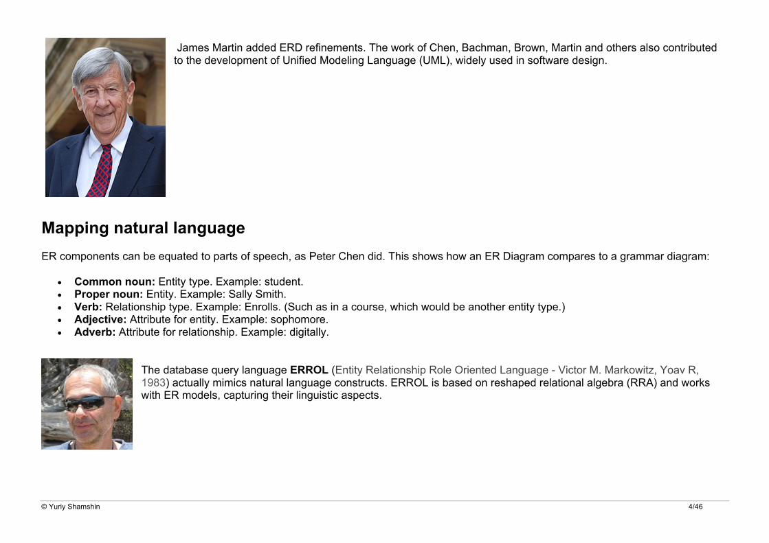
James Martin added ERD refinements. The work of Chen, Bachman, Brown, Martin and others also contributed to the development of Unified Modeling Language (UML), widely used in software design.
Mapping natural language ER components can be equated to parts of speech, as Peter Chen did. This shows how an ER Diagram compares to a grammar diagram:
• Common noun: Entity type. Example: student. • Proper noun: Entity. Example: Sally Smith. • Verb: Relationship type. Example: Enrolls. (Such as in a course, which would be another entity type.) • Adjective: Attribute for entity. Example: sophomore. • Adverb: Attribute for relationship. Example: digitally.
The database query language ERROL (Entity Relationship Role Oriented Language - Victor M. Markowitz, Yoav R, 1983) actually mimics natural language constructs. ERROL is based on reshaped relational algebra (RRA) and works with ER models, capturing their linguistic aspects.

© Yuriy Shamshin 5/46
Uses of entity relationship diagrams • Database design: ER diagrams are used to model and design relational databases, in terms of logic and business rules (in a logical
data model) and in terms of the specific technology to be implemented (in a physical data model.) In software engineering, an ER diagram is often an initial step in determining requirements for an information systems project. It’s also later used to model a particular database or databases. A relational database has an equivalent relational table and can potentially be expressed that way as needed.
• Database troubleshooting: ER diagrams are used to analyze existing databases to find and resolve problems in logic or deployment. Drawing the diagram should reveal where it’s going wrong.
• Business information systems: The diagrams are used to design or analyze relational databases used in business processes. Any business process that uses fielded data involving entities, actions and interplay can potentially benefit from a relational database. It can streamline processes, uncover information more easily and improve results.
• Business process re-engineering (BPR): ER diagrams help in analyzing databases used in business process re-engineering and in modeling a new database setup.
• Education: Databases are today’s method of storing relational information for educational purposes and later retrieval, so ER Diagrams can be valuable in planning those data structures.
• Research: Since so much research focuses on structured data, ER diagrams can play a key role in setting up useful databases to analyze the data.

© Yuriy Shamshin 6/46
The components and features of an ER diagram ERD are composed of entities, relationships and attributes. They also depict cardinality, which defines relationships in terms of numbers.
Entity A definable thing - such as a person, object, concept or event - that can have data stored about it. Think of entities as nouns. Examples: a customer, student, car or product.
Organisations require information in order to carry out the tasks and activities for which they are responsible. The information that these organisations need could be categorised in a number of ways, for example:
People
• Payroll
• Pensions
• Annual leave
• Sick leave
Things
• Furniture
• Equipment
• Stationery
• Fire extinguishers
Locations
• Offices
• Warehouses
• Stock rooms
Events
• Sale is made
• Purchase order is raised
• Item is hired
• Invoice is issued
Concepts
• Image of product
• Advertising
• Marketing
• Research and development.
Each of these can be regarded as an entity.
Important An entity may represent a category of people, things, events, locations or concepts within the area under consideration. An entity instance is a specific example of an entity. For example, John Smith is an entity instance of an employee entity.
Typically shown as a rectangle.

© Yuriy Shamshin 7/46
Entity type: A group of definable things, such as students or athletes, whereas the entity would be the specific student or athlete. Other examples: customers, cars or products.
Entity set: Same as an entity type, but defined at a particular point in time, such as students enrolled in a class on the first day. Other examples: Customers who purchased last month, cars currently registered in Florida. A related term is instance, in which the specific person or car would be an instance of the entity set.
Entity categories: Entities are categorized as strong, weak or associative. A strong entity can be defined solely by its own attributes, while a weak entity cannot. An associative entity associates entities (or elements) within an entity set.
What Should an Entity Type Be?
SHOULD BE:
• An object that will have many instances in the database • An object that will be composed of multiple attributes • An object that we are trying to model
SHOULD NOT BE:
• A user of the database system • An output of the database system (e.g. a report)
Example for db "Movie"
• The actor ”Bruce Willis” should not be an entity type - there is only one instance. • ”Middle-aged actors” is not an entity type - could be a query • Year is not an entity because it does not have multiple attributes (that we want to model, anyway) • The title of a film is not an entity type, unless we want to associate more info with each title (like relationships among movies with that
title)

© Yuriy Shamshin 8/46
Identifiers Entity keys (identifiers): Refers to an attribute that uniquely defines an entity in an entity set. Entity keys can be super, candidate or primary.
• Super key: A set of attributes (one or more) that together define an entity in an entity set. • Candidate key: A minimal super key, meaning it has the least possible number of attributes to still be a super key. An entity set may
have more than one candidate key. • Primary key: A candidate key chosen by the database designer to uniquely identify the entity set. • Foreign key: Identifies the relationship between different entities. When a copy of the primary key for one entity is included in the
collection of attributes of another entity, the copy of the primary key held in the second entity is known as a foreign key.
Identifier (super key) design criteria
• Should not change in value • Should not be null • No “intelligent identifiers” (e.g. containing locations or people that might change) • Substitute new, simple keys for long, composite keys
Simple Key Attribute and Composite Key Attribute

© Yuriy Shamshin 9/46
Declaring a primary key
PRIMARY KEY (<list of attributes>)
mysql> CREATE TABLE Student (
sid VARCHAR(10) PRIMARY KEY,
name VARCHAR(20),
address VARCHAR(20)
);
mysql> INSERT INTO Student VALUES ('12345-6789', 'Bill Gades', 'No Way 8');
1 row inserted.
mysql> INSERT INTO Student VALUES ('12345-6789', 'Bill Gades', 'No Way 8');
ERROR at line 1:
INSERT INTO Student VALUES ('12345-6789', 'Bill Gades', 'No Way 8');
#1062 - Duplicate entry '12345-6789' for key 'PRIMARY'
mysql> INSERT INTO Student VALUES ('12345-6789', 'Bill Gades', 'No Way 8');
ERROR at line 1:
INSERT INTO Student VALUES (NULL,’Don Pedro’,’No Way 8’)
#1048 - Column 'sid' cannot be null
mysql> SELECT * FROM Student;
1 row returned.
mysql> DROP TABLE Student;
© Yuriy Shamshin 10/46
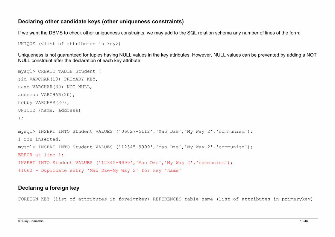
Declaring other candidate keys (other uniqueness constraints)
If we want the DBMS to check other uniqueness constraints, we may add to the SQL relation schema any number of lines of the form:
UNIQUE (<list of attributes in key>)
Uniqueness is not guaranteed for tuples having NULL values in the key attributes. However, NULL values can be prevented by adding a NOT NULL constraint after the declaration of each key attribute.
mysql> CREATE TABLE Student (
sid VARCHAR(10) PRIMARY KEY,
name VARCHAR(30) NOT NULL,
address VARCHAR(20),
hobby VARCHAR(20),
UNIQUE (name, address)
); mysql> INSERT INTO Student VALUES ('06027-5112','Mao Dze','My Way 2','communism');
1 row inserted.
mysql> INSERT INTO Student VALUES ('12345-9999','Mao Dze','My Way 2','communism');
ERROR at line 1:
INSERT INTO Student VALUES ('12345-9999','Mao Dze','My Way 2','communism');
#1062 - Duplicate entry 'Mao Dze-My Way 2' for key 'name'
Declaring a foreign key
FOREIGN KEY (list of attributes in foreignkey) REFERENCES table-name (list of attributes in primarykey)

© Yuriy Shamshin 11/46
Relationship How entities act upon each other or are associated with each other. Think of relationships as verbs. For example, the named student might register for a course. The two entities would be the student and the course, and the relationship depicted is the act of enrolling, connecting the two entities in that way.
Relationships are typically shown as diamonds or labels directly on the connecting lines.
Degree of a relationship set: The number of different entity sets participating in a relationship set is called as degree of a relationship set.
1. Unary Relationship When there is only ONE entity set participating in a relation, the relationship is called as unary relationship. For example, one person is married to only one person.
Many-to-many 2. Binary Relationship When there are TWO entities set participating in a relation, the relationship is called as binary relationship.For example, Student is enrolled in Course.
© Yuriy Shamshin 12/46
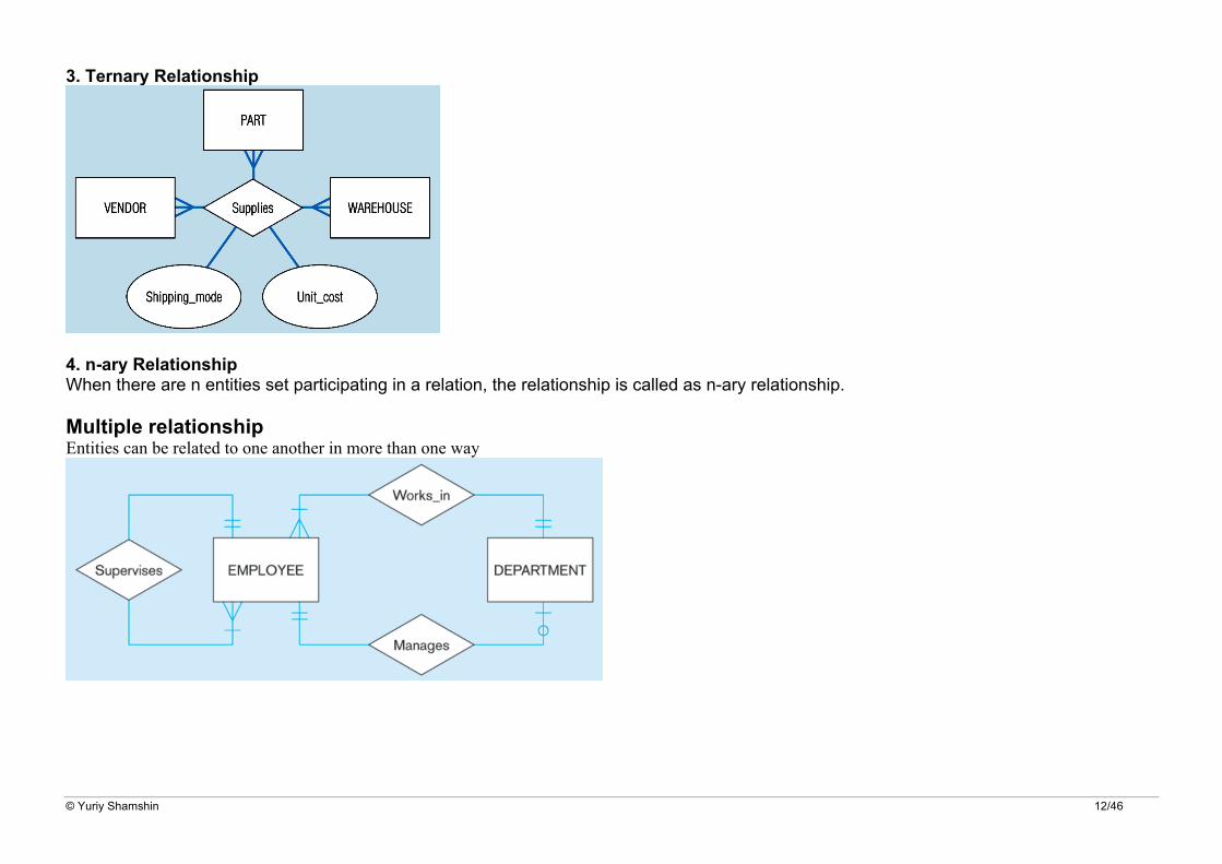
3. Ternary Relationship
4. n-ary Relationship When there are n entities set participating in a relation, the relationship is called as n-ary relationship. Multiple relationship Entities can be related to one another in more than one way
© Yuriy Shamshin 13/46
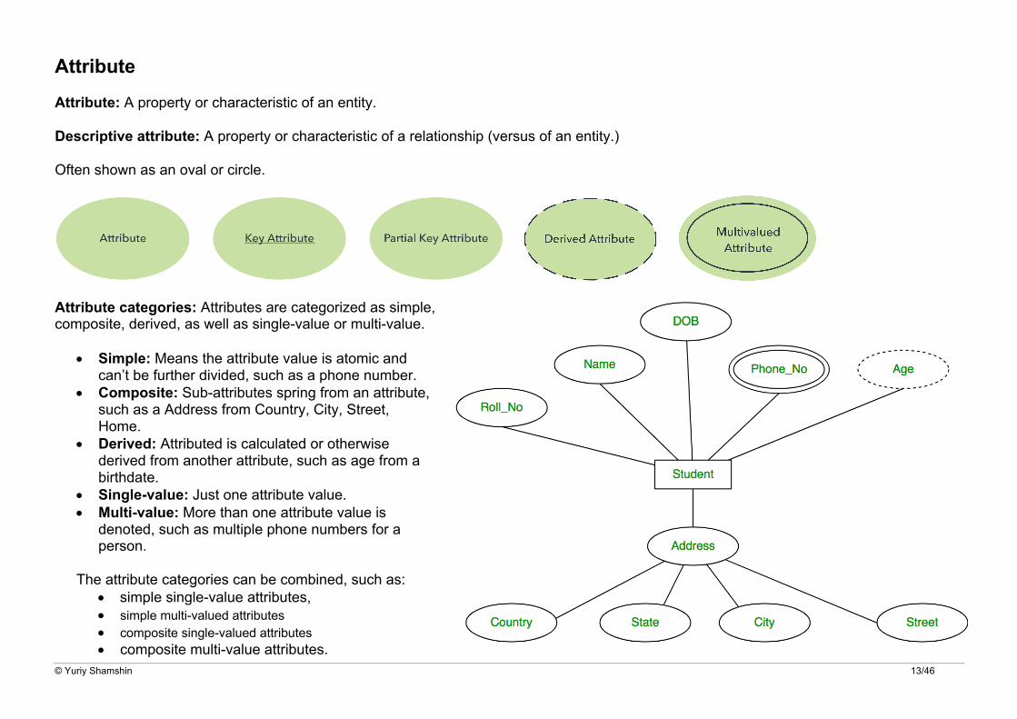
Attribute Attribute: A property or characteristic of an entity.
Descriptive attribute: A property or characteristic of a relationship (versus of an entity.)
Often shown as an oval or circle.
Attribute categories: Attributes are categorized as simple, composite, derived, as well as single-value or multi-value.
• Simple: Means the attribute value is atomic and can’t be further divided, such as a phone number.
• Composite: Sub-attributes spring from an attribute, such as a Address from Country, City, Street, Home.
• Derived: Attributed is calculated or otherwise derived from another attribute, such as age from a birthdate.
• Single-value: Just one attribute value. • Multi-value: More than one attribute value is
denoted, such as multiple phone numbers for a person.
The attribute categories can be combined, such as: • simple single-value attributes, • simple multi-valued attributes • composite single-valued attributes • composite multi-value attributes.
© Yuriy Shamshin 14/46
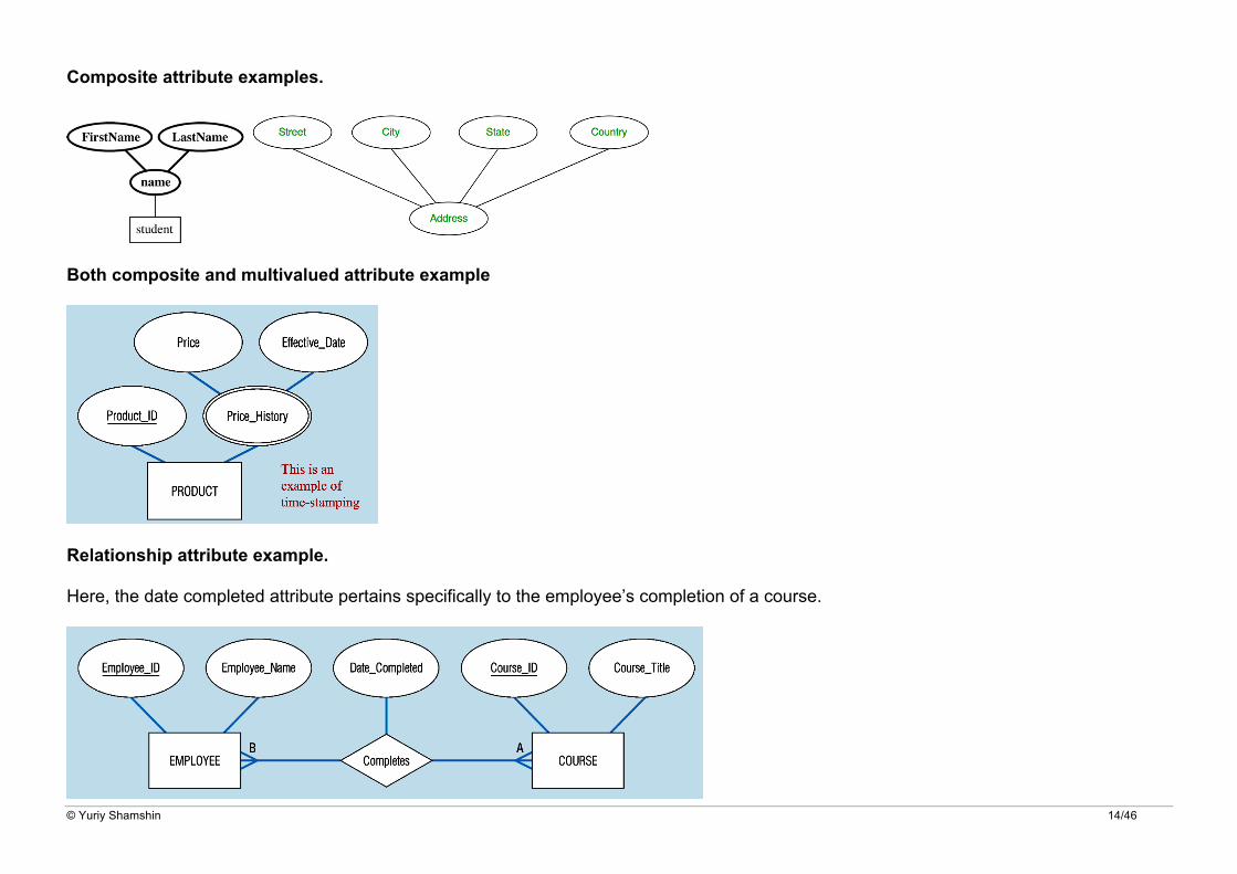
Composite attribute examples.
Both composite and multivalued attribute example
Relationship attribute example.
Here, the date completed attribute pertains specifically to the employee’s completion of a course.

© Yuriy Shamshin 15/46
Cardinality Defines the numerical attributes of the relationship between two entities or entity sets. The three main cardinal relationships are one-to-one (1:1), one-to-many (1:m), and many-many (m:n).
A one-to-one example: would be one student associated with one login name.
A one-to-many example (or many-to-one, depending on the relationship direction): One product line contains multiple products.
Many-to-many example: Students as a group are associated with multiple faculty members (teachers), and faculty members (teachers) in turn are associated with multiple students.
Cardinality views: Cardinality can be shown as look-across or same-side, depending on where the symbols are shown.
Cardinality constraints and obligated (or participation constraint): The minimum or maximum numbers that apply to a relationship.

© Yuriy Shamshin 16/46
Weak Entities Problem: Dependent_name not unique (not even together with Date_of_Birth)
Strong entity type • exist independently of other types of entities • has its own unique identifier • represented with single-line rectangle
Weak entity type • dependent on a strong entity… cannot exist on its own • does not have a unique identifier • represented with double-line rectangle
Identifying relationship • links strong entity type to weak entity type • represented with double line diamond
Always possible to add "surrogate" identifier to avoid Weak Entities!
Associative Entities
• It’s an entity type – it has attributes, identifier. • AND it’s a relationship – it links entities together. • Should be seen as a way of visualizing the above, but: Behaves in all ways just like an entity type.

© Yuriy Shamshin 17/46
Values The following are examples of one set of values for a particular instance of each entity. Every occurrence of an entity will have its own set of values for attributes it possesses.
Entity: House
Attributes:
Values:
Entity: Book
Attributes:
Values:
Entity: Employee
Attributes:
Values:

© Yuriy Shamshin 18/46
Nulls
A null is a special symbol, independent of data type, which means either unknown or inapplicable. It does not mean zero or blank. Features of null include:
• No data entry • Not permitted in the primary key • Should be avoided in other attributes • Can represent
o An unknown attribute value o A known, but missing, attribute value o A “not applicable” condition
• Can create problems when functions such as COUNT, AVERAGE and SUM are used • Can create logical problems when relational tables are linked
NOTE: The result of a comparison operation is null when either argument is null. The result of an arithmetic operation is null when either argument is null (except functions that ignore nulls).
© Yuriy Shamshin 19/46
Entity Relationship Diagram Tutorial Here are some best practice tips for constructing an ERD:
1. Purpose and scope: Define the purpose and scope of what you’re analyzing or modeling. Add a description of your Subject Area. Document any assumptions and restrictions then you make. Show the level of detail necessary for your purpose. You might want to draw a conceptual, logical or physical model, depending on the detail needed. (See above for descriptions of those levels.)
2. Entities: Identify the entities that are involved. Identify all of the entities you will use. An entity is a description of something that your system stores information about. This could be a customer, a manager, an invoice, a schedule, etc. Draw a rectangle (or your system’s choice of shape) for each entity you can think of on your page and labeling them as nouns. Keep them spaced out a bit.
3. Relationships: Determine how the entities are all related. Look at two entities, are they related? If so draw a solid line connecting the two entities and label them. Some entities may not be related, and that’s fine. In different notation systems, the relationship could be labeled in a diamond, another rectangle or directly on top of the connecting line. How are the entities related? Write a brief description of how they are related. Each of your entities may not have any relationships, some may have multiple relationships. That is okay.
4. Cardinality: Show whether 1-1, 1-many or many-to-many. 5. Obligated (or participation): Show whether the relationship is mandatory or optional. 6. Attributes: Layer in more detail by adding attributes of entities. Attributes are often shown as ovals. Any key attributes of entities should
be added. 7. Analyze and complete the diagram: Execute the tips for effective ER diagrams:
a) Make sure the ER diagram supports all the data you need to store. b) Make sure all your entities and relationships and attribute are labeled on your diagram. c) Make sure that each entity only appears once per diagram. Eliminate any redundant entities. d) Examine relationships between entities closely. Are they necessary? Are there any relationships missing? Eliminate any redundant
relationships. Don't connect relationships to each other. e) Use colors to highlight important portions of your diagram. f) You can transition relational tables and ER diagrams back and forth, if that helps you achieve your goal. g) If you’re troubleshooting a database problem, watch for holes in relationships or missing entities or attributes.

© Yuriy Shamshin 20/46
Steps to Create an ERD 1. Let's study them with an example: In a university, a Student enrolls in Courses. A student must be assigned to at least one or more Courses. Each course is taught by a single Professor. To maintain instruction quality, a Professor can deliver only one course
2.
3.
4,5.
6.
7.

© Yuriy Shamshin 21/46
Create ERD from existing database. There are two reasons to create a database diagram:
• designing a new schema, • document your existing structure.
If you have an existing database you need to document, you can create a database diagram using data directly from your database.
You can export your database structure as a CSV file, then have a program generate the ERD automatically (for example on smartdraw.com site).
This will be the most accurate potrait of your database and will require no drawing on your part.
Here's an example of a very basic database structure generated from data.
If you want to create a new plan, you can also edit the generated diagram and collaborate with your team on what changes to make.
-- Export your database structure as a CSV file -- SELECT DISTINCT '' as DatabaseName, SDTables.TABLE_SCHEMA as ParentSchema, SDTables.TABLE_NAME as ParentTable, SDColumns.COLUMN_NAME as ColumnName, SDColumns.ORDINAL_POSITION as ColumnOrder, SDColumns.DATA_TYPE as DataType, SDColumns.CHARACTER_MAXIMUM_LENGTH as ColumnSize, SDConstraints.CONSTRAINT_TYPE as ConstraintType, SDKeys.REFERENCED_TABLE_SCHEMA as ChildSchema, SDKeys.REFERENCED_TABLE_NAME as ChildTable, SDKeys.REFERENCED_COLUMN_NAME as ChildColumn

© Yuriy Shamshin 22/46
FROM INFORMATION_SCHEMA.TABLES SDTables LEFT JOIN INFORMATION_SCHEMA.COLUMNS SDColumns ON SDTables.TABLE_SCHEMA = SDColumns.TABLE_SCHEMA AND SDTables.TABLE_NAME = SDColumns.TABLE_NAME LEFT JOIN INFORMATION_SCHEMA.KEY_COLUMN_USAGE SDKeys ON SDColumns.TABLE_SCHEMA = SDKeys.TABLE_SCHEMA AND SDColumns.TABLE_NAME = SDKeys.TABLE_NAME AND SDColumns.COLUMN_NAME = SDKeys.COLUMN_NAME LEFT JOIN INFORMATION_SCHEMA.TABLE_CONSTRAINTS SDConstraints ON SDKeys.CONSTRAINT_SCHEMA = SDConstraints.CONSTRAINT_SCHEMA AND SDKeys.CONSTRAINT_NAME = SDConstraints.CONSTRAINT_NAME AND SDKeys.TABLE_SCHEMA = SDConstraints.TABLE_SCHEMA AND SDKeys.TABLE_NAME = SDConstraints.TABLE_NAME WHERE SDTables.TABLE_TYPE = 'BASE TABLE' AND SDTables.TABLE_SCHEMA NOT IN ('INFORMATION_SCHEMA' , 'mysql','performance_schema','sys') ORDER BY ParentSchema, ParentTable, ColumnOrder

© Yuriy Shamshin 23/46
Different Types of Keys in DBMS There are following 10 important keys in DBMS:
1. Super key 2. Candidate key 3. Primary key 4. Alternate key 5. Foreign key 6. Partial key 7. Composite key 8. Unique key 9. Surrogate key 10. Secondary key
1. Super Key
• A super key is a set of attributes that can identify each tuple uniquely in the given relation. • A super key is not restricted to have any specific number of attributes. • Thus, a super key may consist of any number of attributes.
Example. Consider the following Student schema
Student ( roll , name , sex , age , address , class , section )
Given below are the examples of super keys since each set can uniquely identify each student in the Student table
• ( roll , name , sex , age , address , class , section ) • ( class , section , roll ) • (class , section , roll , sex ) • ( name , address )
Note. All the attributes in a super key are definitely sufficient to identify each tuple uniquely in the given relation but all of them may not be necessary.

© Yuriy Shamshin 24/46
2. Candidate Key
A minimal super key is called as a candidate key.
OR
A set of minimal attribute(s) that can identify each tuple uniquely in the given relation is called as a candidate key.
Example. Consider the following Student schema
Student ( roll , name , sex , age , address , class , section )
Given below are the examples of candidate keys since each set consists of minimal attributes required to identify each student uniquely in the Student table
• ( class , section , roll ) • ( name , address )
Notes.
• All the attributes in a candidate key are sufficient as well as necessary to identify each tuple uniquely. • Removing any attribute from the candidate key fails in identifying each tuple uniquely. • The value of candidate key must always be unique. • The value of candidate key can never be NULL. • It is possible to have multiple candidate keys in a relation. • Those attributes which appears in some candidate key are called as prime attributes.
3. Primary Key
A primary key is a candidate key that the database designer selects while designing the database.
OR
Candidate key that the database designer implements is called as a primary key.
Notes.
© Yuriy Shamshin 25/46
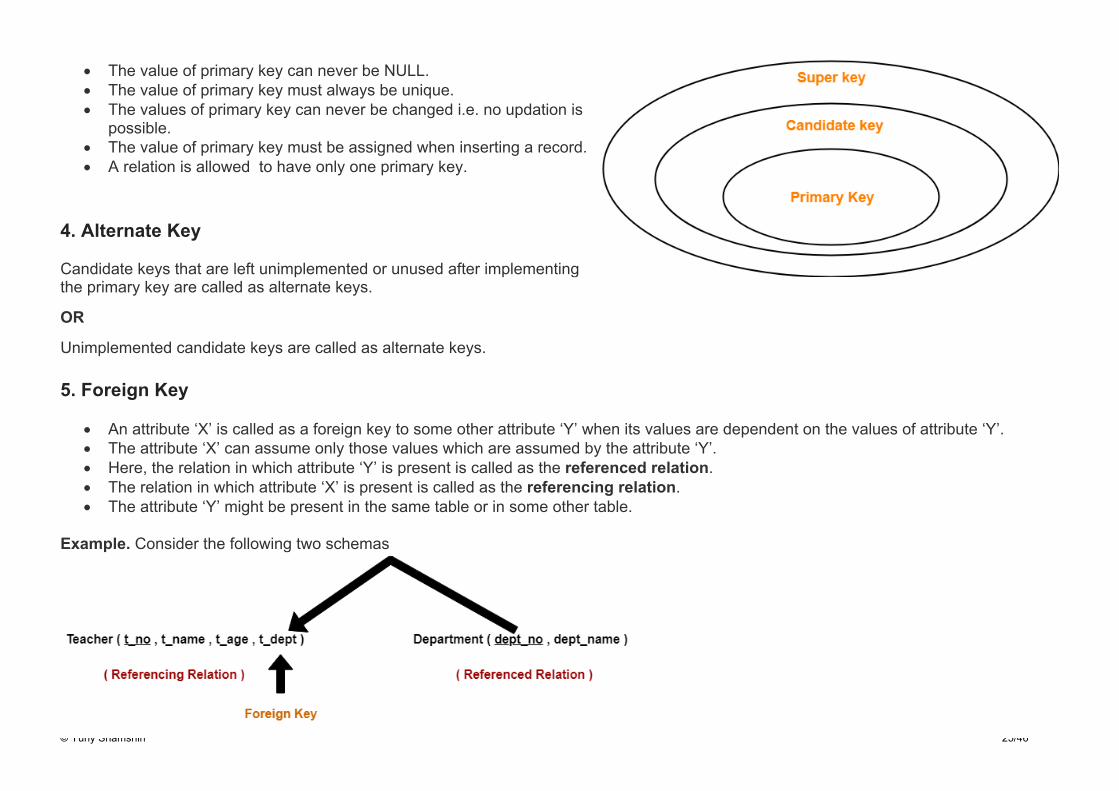
• The value of primary key can never be NULL. • The value of primary key must always be unique. • The values of primary key can never be changed i.e. no updation is
possible. • The value of primary key must be assigned when inserting a record. • A relation is allowed to have only one primary key.
4. Alternate Key
Candidate keys that are left unimplemented or unused after implementing the primary key are called as alternate keys.
OR
Unimplemented candidate keys are called as alternate keys.
5. Foreign Key
• An attribute ‘X’ is called as a foreign key to some other attribute ‘Y’ when its values are dependent on the values of attribute ‘Y’. • The attribute ‘X’ can assume only those values which are assumed by the attribute ‘Y’. • Here, the relation in which attribute ‘Y’ is present is called as the referenced relation. • The relation in which attribute ‘X’ is present is called as the referencing relation. • The attribute ‘Y’ might be present in the same table or in some other table.
Example. Consider the following two schemas

© Yuriy Shamshin 26/46
Here, t_dept can take only those values which are present in dept_no in Department table since only those departments actually exist.
Notes.
• Foreign key references the primary key of the table. • Foreign key can take only those values which are present in the primary key of the referenced relation. • Foreign key may have a name other than that of a primary key. • Foreign key can take the NULL value. • There is no restriction on a foreign key to be unique. • In fact, foreign key is not unique most of the time. • Referenced relation may also be called as the master table or primary table. • Referencing relation may also be called as the foreign table.
6. Partial Key
• Partial key is a key using which all the records of the table can not be identified uniquely. • However, a bunch of related tuples can be selected from the table using the partial key.
Example. Consider the following schema
Department (Emp_no, Dependent_name , Relation )
Emp_no Dependent_name Relation
E1 Egils Mother
E1 Ozols Father
E2 Darts Father
E2 Forevers Son
Here, using partial key Emp_no, we can not identify a tuple uniquely but we can select a bunch of tuples from the table.
© Yuriy Shamshin 27/46
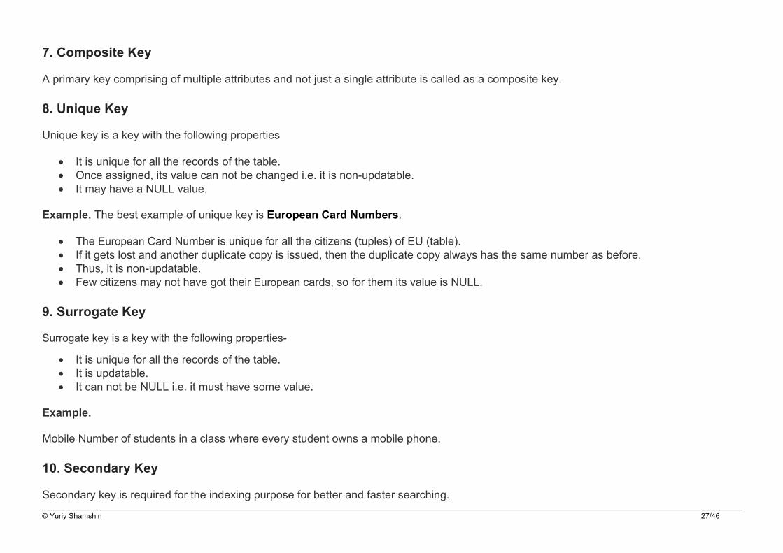
7. Composite Key
A primary key comprising of multiple attributes and not just a single attribute is called as a composite key.
8. Unique Key
Unique key is a key with the following properties
• It is unique for all the records of the table. • Once assigned, its value can not be changed i.e. it is non-updatable. • It may have a NULL value.
Example. The best example of unique key is European Card Numbers.
• The European Card Number is unique for all the citizens (tuples) of EU (table). • If it gets lost and another duplicate copy is issued, then the duplicate copy always has the same number as before. • Thus, it is non-updatable. • Few citizens may not have got their European cards, so for them its value is NULL.
9. Surrogate Key
Surrogate key is a key with the following properties-
• It is unique for all the records of the table. • It is updatable. • It can not be NULL i.e. it must have some value.
Example.
Mobile Number of students in a class where every student owns a mobile phone.
10. Secondary Key
Secondary key is required for the indexing purpose for better and faster searching.

© Yuriy Shamshin 28/46
ERD symbols on several notation styles There are several notation systems, which are similar but vary in a few specifics.
Chen notation style

© Yuriy Shamshin 29/46

© Yuriy Shamshin 30/46
Information Engineering (Crow’s Foot) notation style

© Yuriy Shamshin 31/46
Martin notation style
© Yuriy Shamshin 32/46
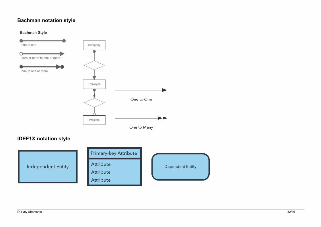
Bachman notation style
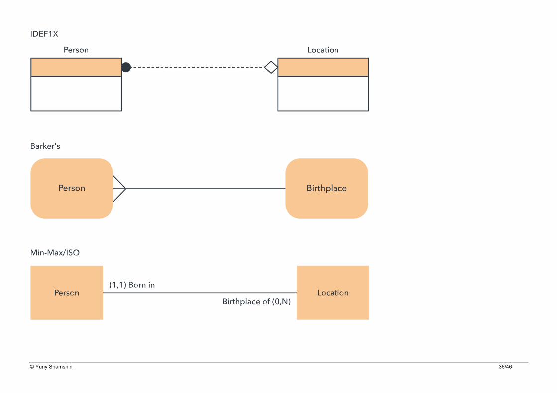
IDEF1X notation style

© Yuriy Shamshin 33/46
© Yuriy Shamshin 34/46
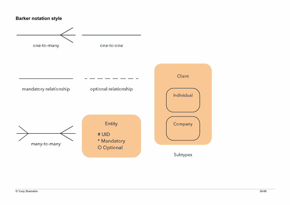
Barker notation style

© Yuriy Shamshin 35/46
ERD Examples
Following are examples of ERD diagrams made in each system.
© Yuriy Shamshin 36/46

© Yuriy Shamshin 37/46
ERD Examples 1. ERD Example (Chen’s notation).
Entity Relationship Diagram - Computer Game

© Yuriy Shamshin 38/46
2. ERD Example (Chen’s - Crow’s Foot notation).
© Yuriy Shamshin 39/46
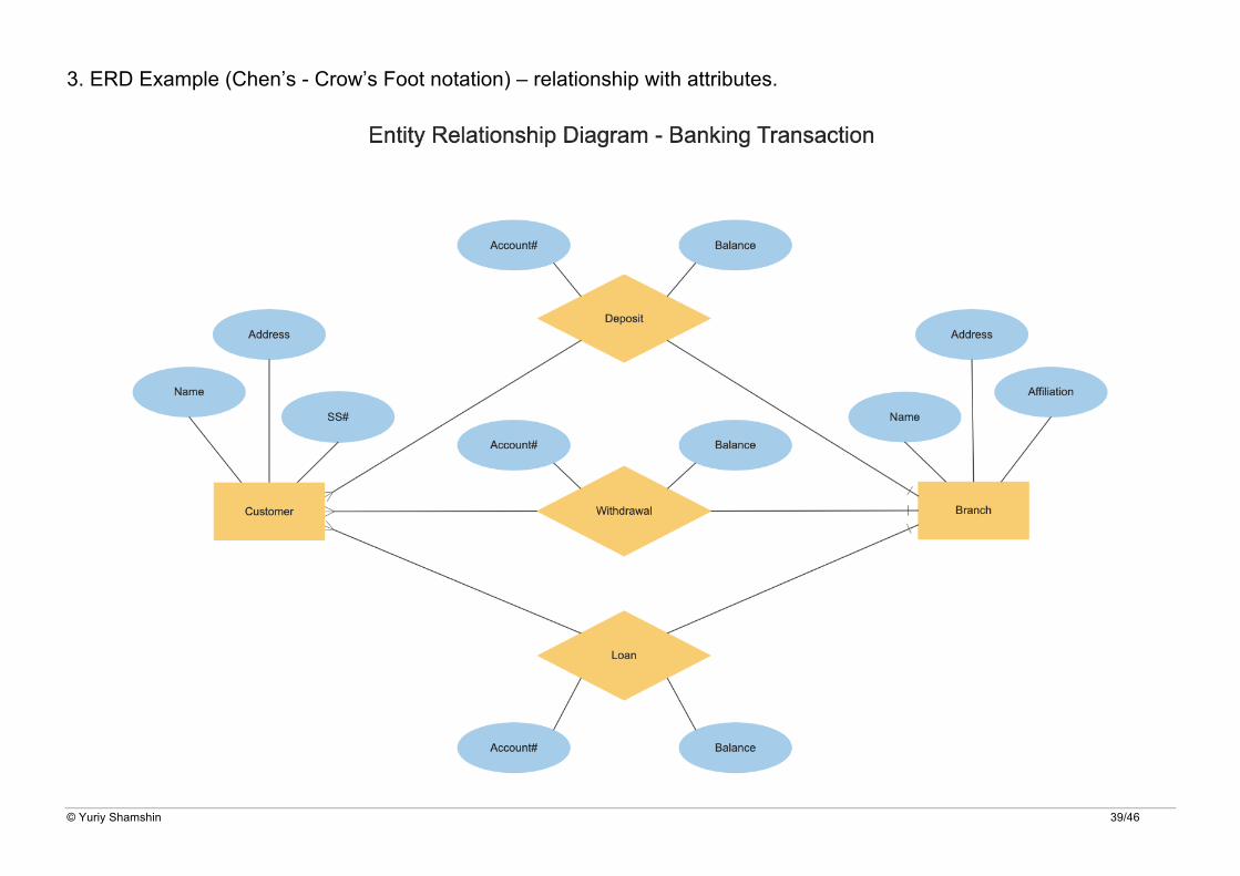
3. ERD Example (Chen’s - Crow’s Foot notation) – relationship with attributes.
© Yuriy Shamshin 40/46
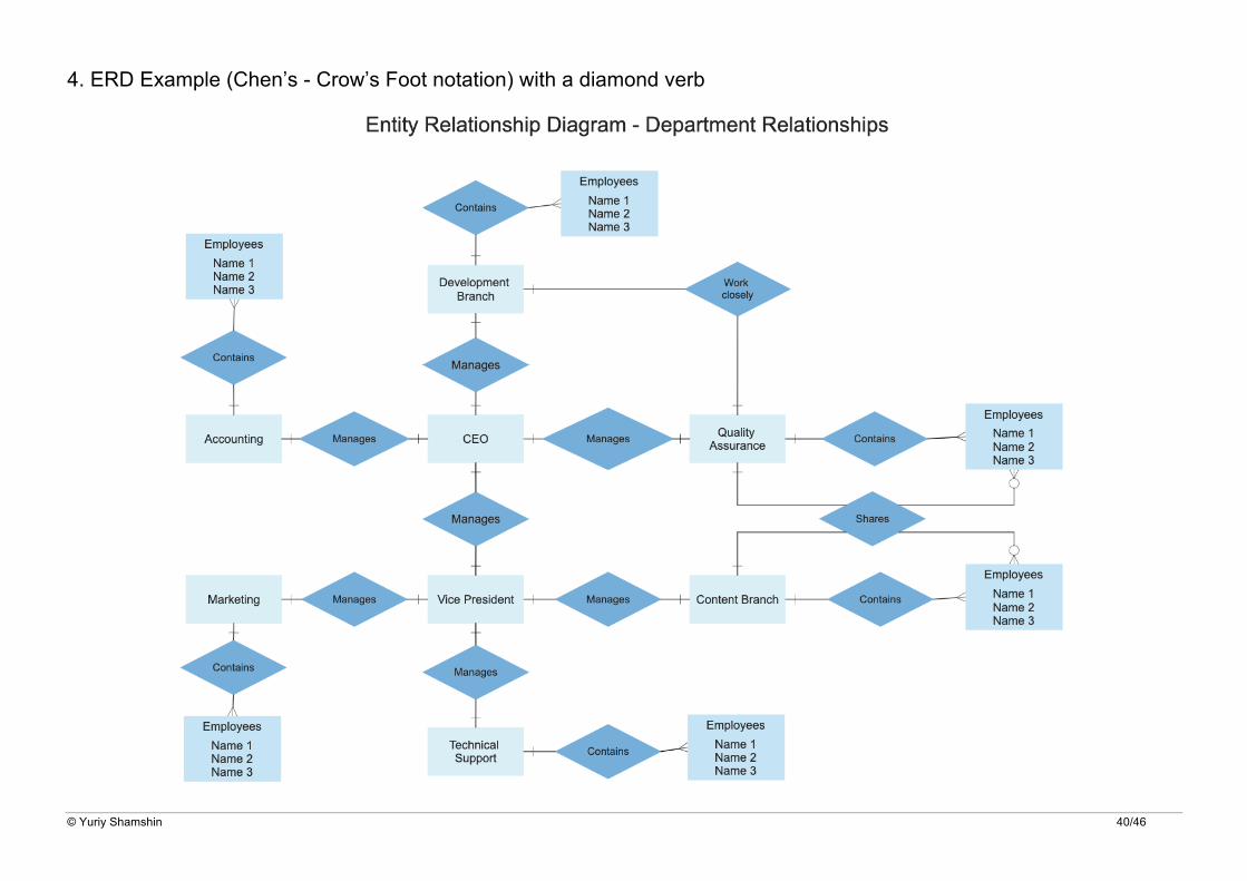
4. ERD Example (Chen’s - Crow’s Foot notation) with a diamond verb
© Yuriy Shamshin 41/46
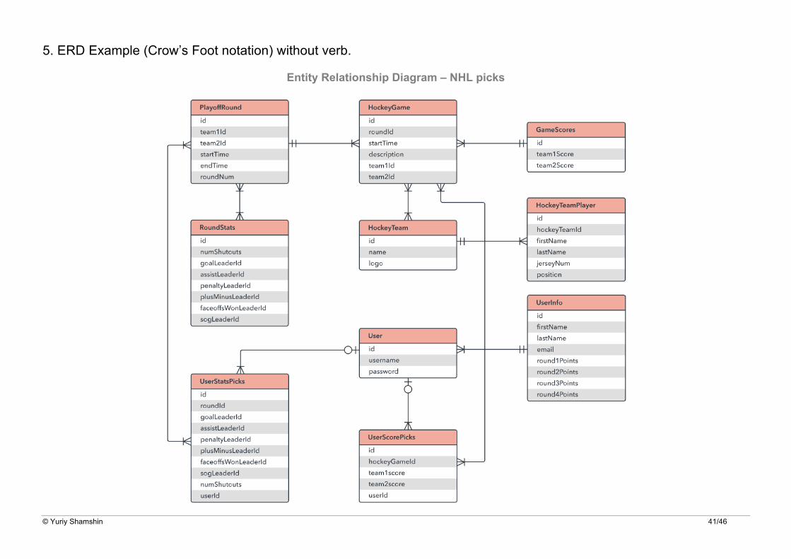
5. ERD Example (Crow’s Foot notation) without verb.
Entity Relationship Diagram – NHL picks

© Yuriy Shamshin 42/46
6. ERD Example (Crow’s Foot notation) with over line verb
Entity Relationship Diagram – Online University - Courses

© Yuriy Shamshin 43/46
7. ERD Example (Crow’s Foot notation) with data types description
Entity Relationship Diagram – Online University - Session

© Yuriy Shamshin 44/46
8. ERD Example (Crow’s Foot notation) with keys description
Entity Relationship Diagram – Online University - Session

© Yuriy Shamshin 45/46
9. ERD Example (Min-Max/ISO notation) with cardinality and keys descriptions
Entity Relationship Diagram – Blog

© Yuriy Shamshin 46/46