LRM207x, LRM208x, LRM209x Datasheet 1/15...
15
LRM207x, LRM208x, LRM209x Datasheet OccuSwitch DALI sensor/controller General description The OccuSwitch DALI is a combined sensor and controller. It will dim and switch the lights in a room or area on occupancy and available daylight, with options for local override, parallel operation and network links to Building Management Systems (BMS). Savings up to 75% can be achieved with functions like daylight depending dimming, occupancy control and over dimension correction. The OccuSwitch DALI is designed for an office area of 20 .. 25 m 2 , or a classroom of around 40 m 2 but the area can be doubled, or even tripled, with the extension sensor LRM8118. Up to 15 luminaires can be controlled. A detachable wiring connector enables easy installation and mounting in the ceiling. Separate Wieland cables are available for an even easier, fast and trouble-free installation. It is possible to link up to 22 (advanced only) OccuSwitch DALI units in parallel to cover larger area’s with a specific “open plan” mode to ensure maximum comfort and savings. The LRM2090 can be linked to most BMS or other control systems that have standard DALI interfaces. This makes simple yet very effective control scenarios in a building possible. The LRM2095 has tunable white control, capable of creating atmospheres with different color temperature. The LRM2095 is part of the SchoolVision proposition. The OccuSwitch DALI family exists of: LRM2070 Basic functionality LRM2071 Basic functionality + Enocean ® interface LRM2080 Parallel operation LRM2081 Parallel operation + Enocean ® interface LRM2090 DALI interface for BMS or othernetwork LRM2091 DALI interface for BMS + Enocean ® interface LRM2095 Tunable white + interface forlocal/central control LCC2070 Wieland cable for LRM207x LCC2080 Wieland cable for LRM208x and LRM209x LRH2070 Ceiling mounting box LCU2070 Push-button Unit for 4 switches LCU2071 Additional Push-button Unit (for LRM2095 only) IRT8097 OmniProg easy, commissioning tool IRT8099/10 OmniProg, commissioning tool IRT8096 OmniProg, dedicated for LRM2095 1/15 52 95 80 2 Dimensions in mm LCC2070 cable set LCC2080 cable set 7-pole STELVIO plug MRT3 P 5,08/07 V01 VE 500 GST18i3 BST14i2 female 7-pole STELVIO plug MRT3 P 5,08/07 V01 VE LN DA X BST14i2 female GST18i3 BST14i2 female DA X BST14i2 male LN Ø 95 mm 60 mm 40 mm 60 mm 52 mm 2 inch
Transcript of LRM207x, LRM208x, LRM209x Datasheet 1/15...

LRM207x, LRM208x, LRM209x DatasheetOccuSwitch DALI sensor/controller
General description
The OccuSwitch DALI is a combined sensor and controller. It will dim and switch the lights in a room or area on occupancy and available daylight, with options for local override, parallel operation and network links to Building Management Systems (BMS).Savings up to 75% can be achieved with functions like daylight depending dimming, occupancy control and over dimension correction.The OccuSwitch DALI is designed for an office area of 20 .. 25 m2, or a classroom of around 40 m2 but the area can be doubled, or even tripled, with the extension sensor LRM8118. Up to 15 luminaires can be controlled.A detachable wiring connector enables easy installation and mounting in the ceiling. Separate Wieland cables are available for an even easier, fast and trouble-free installation.It is possible to link up to 22 (advanced only) OccuSwitch DALI units in parallel to cover larger area’s with a specific “open plan” mode to ensure maximum comfort and savings.The LRM2090 can be linked to most BMS or other control systems that have standard DALI interfaces. This makes simple yet very effective control scenarios in a building possible.The LRM2095 has tunable white control, capable of creating atmospheres with different color temperature. The LRM2095 is part of the SchoolVision proposition.
The OccuSwitch DALI family exists of:LRM2070 Basic functionalityLRM2071 Basic functionality + Enocean® interfaceLRM2080 Parallel operationLRM2081 Parallel operation + Enocean® interfaceLRM2090 DALI interface for BMS or othernetworkLRM2091 DALI interface for BMS + Enocean® interfaceLRM2095 Tunable white + interface forlocal/central controlLCC2070 Wieland cable for LRM207xLCC2080 Wieland cable for LRM208x and LRM209xLRH2070 Ceiling mounting boxLCU2070 Push-button Unit for 4 switchesLCU2071 Additional Push-button Unit (for LRM2095 only)IRT8097 OmniProg easy, commissioning toolIRT8099/10 OmniProg, commissioning toolIRT8096 OmniProg, dedicated for LRM2095
1/15
52
95
80
2
Dimensions in mm
LCC2070 cable set
LCC2080 cable set
7-pole STELVIO plug MRT3 P 5,08/07 V01 VE
500
GST18i3
BST14i2 female
7-pole STELVIO plug MRT3 P 5,08/07 V01 VE
L N
DA X
BST14i2 female
GST18i3
BST14i2 female
DA X
BST14i2 male
L N
Ø 95 mm
60 m
m
40 mm
60 mm
52 mm2 inch

LRM207x, LRM208x, LRM209x DatasheetOccuSwitch DALI sensor/controller
2/15
Applications
The OccuSwitch DALI is designed for use in offices and similar applications like schools, including corridors, meeting rooms, etc. It is optimized for recessed ceiling mounting and for mounting heights between 2.5 and 4 meter.The surface box allows surface mounting as well, with either recessed wiring or surface mounted ducts.The advanced OccuSwitch DALI can be connected in parallel (max 22) to cover larger area’s like open plan offices. The use of different mains groups or even phases is no problem.The OccuSwitch DALI design guide (available on www.philips.com/occuswitchdali) gives all necessary design information for offices, schools and meeting rooms.
Typical applications
Energy indicatorThe LED on the OccuSwitch DALI indicating movement or communication will change color depending on the energy usage. Dimming levels below 30% will show a green color, below 70% yellow, and above red.
Features
Window/corridor and dynamic offset controlFor optimal energy savings the window and corridor luminaires are controlled separately as indicated in the graph. Window-side lights will switch off (or not switch on entrance, the daylight override function) when sufficient daylight is available. The corridor side however will by default dim to minimum only, hence indicating to the user that the system is operational. This feature can be disabled.
LRM2090 / LRM2095
LRM207x LRM208x
80%
100%
30%
1%
max. offsetLRM2080

LRM207x, LRM208x, LRM209x DatasheetOccuSwitch DALI sensor/controller
3/15
DALI addressingThe OccuSwitch DALI can be used with one channel only or two (window / corridor control), using the physical outputs (LRM2070 only). However all versions can be used with DALI addressing as well. Up to 4 channels can be defined.
The additional luminaire groups can switch on together with the window and corridor groups or only switch on manually (absence). All groups will switch off when the area is vacated. Pre-programmed luminaires will be recognized upon start-up.
Auto commissioningThe OccuSwitch DALI can determine the installed lux level and take this as set point for the daylight depending regulation. This is easy to use without the need for a Lux meter.
DALI network interfaceThe LRM2090 can be controlled with a DALI network interface. This means that this device can be connected to most BMS or other control system with a DALI interface. This enables functions like switching on/ of or dim, scenes and queries for lamp/ballast states, the set light level and even more functions.With an specific gateway, supporting the OccuSwitch DALI BMS functions, it is also possible to use parallel occupancy control, very much like the OccuSwitch DALI advanced.
Enocean® interfaceOccuSwitch DALI allows the use of wireless switches with Enocean® RF technology. Both single rocker and dual rocker switches can be used. You can connect up to 4 switches to a single OccuSwitch DALI, if required each with different functions. Switches and OccuSwitch DALI units are bound with each other during the commissioning process. A single switch can be linked to several OccuSwitch DALI units.
Functions
window + corridor + additional presence
window corridor or window + additional absence corridor + additional presence
IRT8097, OmniProg easy IRT8099/10, OmniProg
For all functions 1 0
press shortly0 lights off1 lights on
press longer0 lights dim down1 lights dim up
Binding procedure see www.philips.com/omniprog
Commissioning toolsThe OccuSwitch DALI comes with two commissioning tools, the Omniprog and Omniprog easy. With both tools the light levels can be set, witnessing mode be started and window/corridor be assigned. The Omniprog can also set the desired mode, Start-up behaviour, IR group and assign more luminaire channels.
Witnessing modeWith the Omniprog (easy) the witnessing mode can be started. This makes it possible to check if the OccuSwitch DALI and the connected luminaires are correctly installed and fully operational, Quick and easy.
100 hours burn-inMany lamp manufacturers advise not to dim fluorescent lamps for a 100 hours period prior to normal use. Especially to maintain the light quality at (very) low dimming. The OccuSwitch DALI can do this automatically. During 100 hours lights will not be dimmed, and all dimming functions are adapted.Only during witnessing (to test the installation) and commissioning dimming is allowed to make the necessary adjustments.
DALI group Function
1 Window
2 Corridor
3 Additional presence
4 Additional absence
0
1
0 0
1 1
B A
click click

LRM207x, LRM208x, LRM209x DatasheetOccuSwitch DALI sensor/controller
4/15
Extension sensorThe LRM8118 extension movement detector can be used to double the movement detection area. This sensor is connected to the same DALI channel as the luminaires. Installation is simple since mains is not required.
Smart TimerOn some occasions with very little movement it is possible that the standard delay time of the OccuSwitch DALI is too short. If movement is detected during switch off (including fade this takes 10 seconds), the delay timer is automatically increased by 10 minutes.
The OccuSwitch DALI detection pattern (see drawing) is 4 by 5 meters for small movements (desk work) and 6 by 8 meters for larger movements like walking. We strongly suggest using the 4 by 5 meters for the design. It is also the right range for the Light Sensor (for daylight depending regulation). The detection area of the movement detector can be extended by two extension sensors (LRM8118) each with a equal detection pattern as the OccuSwitch DALI.
LRM8118 extension sensor
Ø 72
25.9
2
Ø 63.5
Dimensions in mm
8m5m
6m
4m
Detection pattern
120°
If the shield is retracted the detection pattern will be cut on one side (120°) as indicted in the diagram.
Push-button Unit The LCU2070 Push-button unit (PBU) makes it possible to connect up to 4 switches to the OccuSwitch DALI, to dim and switch different channels. This PBU is connected to the DALI channel (DA and X (LRM2070/10) or DA only (LRM2080/10 and 2090/10)). It derives its power form the DALI channel, so no additional power supply is required. The PBU uses the same interface technique as the Enocean® or Touch & Dim; press shortly and it will switch on when off, and off when on, pressed for a longer time and it will alternatively dim up and down.Up to two PBUs can be used on a single OccuSwitch DALI. It is possible to interconnect (single) switches to several PBUs to control several OccuSwitch DALI units.
Note: the LCU2070 requires the /10 versions of the OccuSwitch DALI
Black
Black
White
Red
Purple
WhiteGreen
Yellow
SW-COM
DA -
DA +
SW1
SW2
SW-COMSW3
SW4
Push-button common
DALI line on OccuSwitch DALI
Window T&D
Window + Corridor + Extra Auto-on T&D
Push-button commonCorridor T&D
Extra Manual-on T&D
LCU2070/009137 003 35103Made in E.U.PFT yyww
DA+DA-
123456
LCU2070/00 wiring
LCU2070 Push-button unit

LRM207x, LRM208x, LRM209x DatasheetOccuSwitch DALI sensor/controller
5/15
LRM 2090/2091
The BMS version has a second DALI interface (“X”). The OccuSwitch DALI will act as a DALI slave. This interface makes it possible to connect the OccuSwitch DALI to a building management system using a controller with a DALI interface or a DALI gateway.It also makes it possible to use DALI user interfaces to override the OccuSwitch DALI.This interface is fully compliant to DALI but the unit will act, of course, a bit different than a standard DALI ballast.
Response to DALI commandsIf a DALI command is received (for instance a direct arc power command) every lamp on any channel connected to the OccuSwitch DALI will respond, and respond in the same way.The OccuSwitch DALI sends most of these DALI commands directly to the ballasts.Every command that changes the output level will disable the daylight depending regulation, and restart the occupancy timer.
Response to DALI queriesThe OccuSwitch DALI will respond to all DALI queries like a DALI (#102) ballast.A query on the ACTUAL LEVEL will result in the value of the window side (channel 1).The unit performs a regular scan on the connected ballasts. Queries on status and lamp failure will report the result of this scan, if a single ballast reports an error, the OccuSwitch DALI will do as well. Other queries like MAX LEVEL will show the value and status as stored in the OccuSwitch DALI.
Exceptions• TheOccuSwitchDALIwillnotrecallSCENE1.Itwillusethedefault
light level settings and start daylight depending regulation again.• Anycommandresultinginadifferentoutputlevelwill(re)startthe
occupancy timer. If you need to keep the lights on (or off) you need to repeat the command periodically with a shorter repeat time than the set occupancy timer.
Addressing The OccuSwitch DALI supports the standard ways to address units, including physical selection (using the Push-button on the front).Alladdress(includinggrouping)relatedcommandsareNOTrelayedtothe connected ballasts.It is also possible to use the IRT8099/10 OmniProg to set the short address of the unit.This is only possible when the address has not been set before, or after a complete reset (back to basic) of the unit.Aim at the unit with the IRT8099/10 and press within 5 seconds the required 2 digit address on the numeric keypad, for instance 36 or 05.The OccuSwitch DALI will blink its LEDs and connected lights to confirm the new settings.

LRM207x, LRM208x, LRM209x DatasheetOccuSwitch DALI sensor/controller
6/15
> 50 mm
≤ 30 mm
max. 185 mm
3
4 1
2
80-82 mm
Mechanical installation
The OccuSwitch DALI can be mounted in two ways; recessed in the ceiling or surface mounted using the ceiling box. The ceiling box (LRH2070) has a breakout port for cable ducts and a breakout centerpiece.
LRH2070
5 4
1
2
3
LRM20xx
Datasheet
LRM207x, LRM208x, LRM209x DatasheetOccuSwitch DALI sensor/controller
7/15
Electrical installation
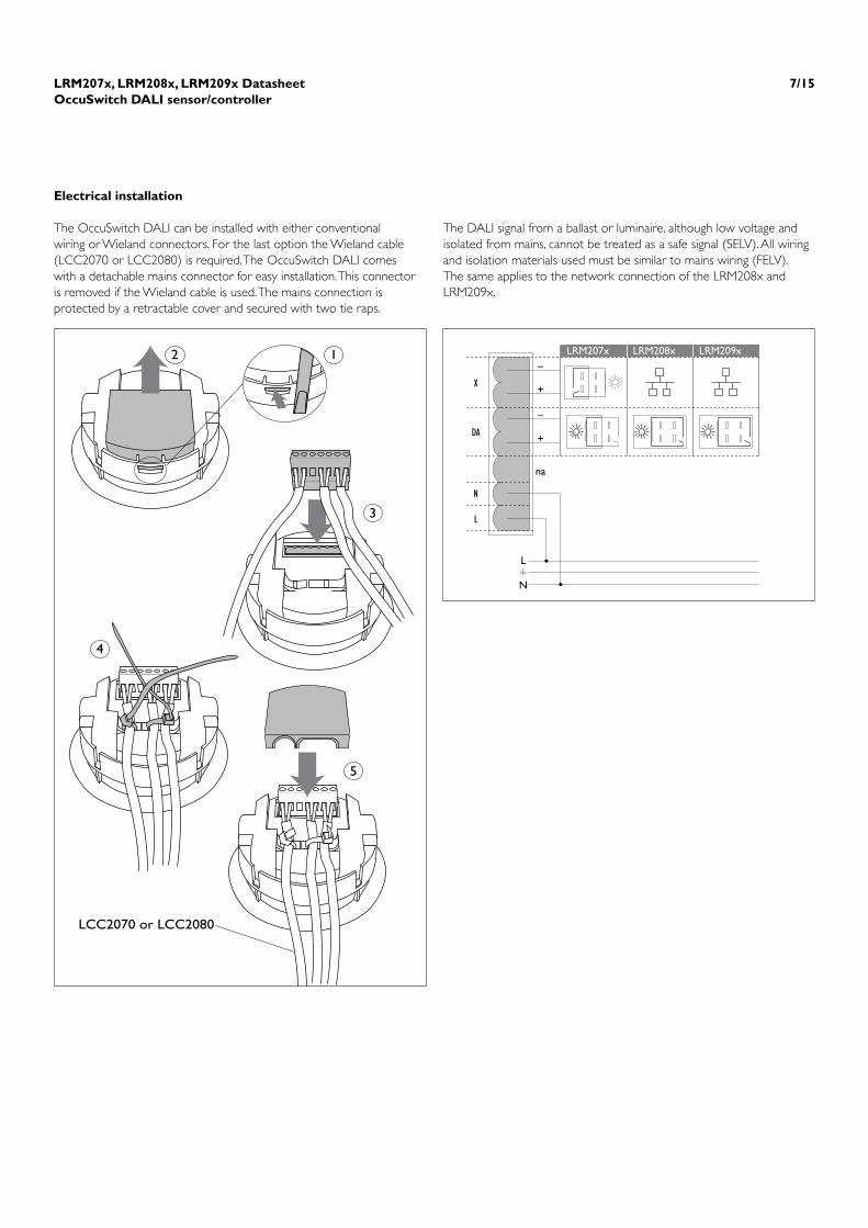
The OccuSwitch DALI can be installed with either conventional wiring or Wieland connectors. For the last option the Wieland cable (LCC2070 or LCC2080) is required. The OccuSwitch DALI comes with a detachable mains connector for easy installation. This connector is removed if the Wieland cable is used. The mains connection is protected by a retractable cover and secured with two tie raps.
The DALI signal from a ballast or luminaire, although low voltage and isolated from mains, cannot be treated as a safe signal (SELV). All wiring and isolation materials used must be similar to mains wiring (FELV).The same applies to the network connection of the LRM208x and LRM209x.
2 1
3
4
5
LCC2070 or LCC2080
L
N
N
L
DA
X
LRM207x LRM208x LRM209x
na
–
+
–
+

LRM207x, LRM208x, LRM209x DatasheetOccuSwitch DALI sensor/controller
8/15
Commissioning
Desired standard light levelThere are three ways to set the light level.
Delay time occupancy control
With the rotary it is possible to select a delay time of either 70s, 5 till 30 min (in steps of 5 minutes).
Further commissioning
OmniProg (easy)The OccuSwitch DALI will acknowledge commissioning commands by flashing the lights.For detailed information please refer to the manual or www.philips.com/omniprogThe OmniProg tool has a low power and very narrow beam to prevent that neigbouring OccuSwitch DALI units are programmed by mistake. You must be within 3 meters of the device and aim exactly at it.
Max. 1m
= 1x
IRT8099/10 commissioning tool
Send command
Automated modeStep 1 Press the OccuSwitch DALI button
for 3 seconds until the LEDs start a yellow/green sequence
Step 2 Release and press again, the LEDs will now blink red/green
Step 3 Clear the area beneath the OccuSwitch DALI
Step 4 Within 10 seconds the auto calibration starts
Lights will switch off and on to determine the installed lux level
Lights will flash to indicate a successful operation
The calibration is finished
Manual with normal controlStep 1 Use a remote or switch to set the
desired light levelStep 2 Press the OccuSwitch DALI button
until the LEDs start a yellow/green sequence
Step 3 Clear the area beneath the OccuSwitch DALI
Step 4 The light level existing 10 seconds after step 2 is used as set point
Lights will flash to indicate a successful operation
The calibration is finished
Manual with OmniProg (easy)Step 1 Use the OmniProg’s up an down keys
to create the desired light levelStep 2 Press the “SAVE” buttonStep 3 The lights will flash once to indicate
calibration was successful
Calibrate light level
Rotary

LRM207x, LRM208x, LRM209x DatasheetOccuSwitch DALI sensor/controller
9/15
Commissioning of switches with Enocean® RF technologyShortly press the front button of the OccuSwitch DALI, all LEDs will flash shortly.Press again but now hold the button down until the green and red LEDs start to flash rapidly.Wait till the flashing slows down.Press one of the keys of the switch you want to bind to the OccuSwitch DALI.The LEDs will flash rapidly again. Wait till the flashing slows down.You can now bind another switch.Press the front button (shortly), or wait for 30 seconds, to stop the commissioning. The green/red flashing will now stop and normal operation is resumed.
If you make a mistake or want to make alterations, stop the commissioning process, and restart again.
ThefollowingsettingsaresentallatoncewiththegreenSENDbutton.After selection of the function the red LED on the transmitter will switch on.
Change IR groupBoth the OccuSwitch DALI and transmitters can operate in 7 different groups. Both the transmitter and OccuSwitch DALI must be in the same groupSelect “group A-G” on the IRT8099, followed by the desired IR group (A-G, buttons 1 .. 7).
Change power-up behaviourThe OccuSwitch DALI switches the output on when it is connected to the mains. If the area is vacated the lights will switch off after 5 minutes. It is possible to leave the output off and start movement detection 30 seconds after the mains is connected.Select “power up ON/Off” on the IRT8099, followed by either “ON” or “off ”.
Restore defaultsTo restore the default settings aim the IRT8099 towards the OccuSwitchDALIandpresson“basics”andpressSEND.
AttentionTheIRT8099willsendallparameterswhentheSENDbuttonis pressed.
Error statesThe OccuSwitch DALI is designed to create (if possible) a safe situation if the device itself or its peripherals fail.Depending on the failure the OccuSwitch DALI will continue “as good as possible” or switch the lights on.The LED on the device will be always yellow and will not switch off, even if there is no movement or communication detected.Please refer to the manual or www.philips.com/OccuSwitch DALI for more information and diagnostic flow charts.
LED
Flash Red, Yellow or Green Movement or communication detected. Red = 100 – 70% Yellow = 70 – 30% Green = 30% - offCirculation (long/short)Yellow/Green Auto commissioning with current light levelRed/Green Auto commissioningGreen/Red DALI commissioning in progress
Continuously Green (when lights are on) In 100 hours burn in mode (no dimming possible)Yellow Internal errorRed Short circuit on DALI channel
Fast sequenceRed/Yellow/Green Trigger received from parallel unit (LRM2080 only)
AttentionThe OccuSwitch DALI should not be used in the following situations
•Inapplicationsoutsidethespecificationrange,mostnotableheightsabove 4 meter.
• Environmentalconditionsotherthaninanormalofficeenvironment(temperature, humidity).
• Inapplicationswithheatsourceslikeelectricalheaters,withinthedetection range of the device
• Inapplicationswith(semicontinuous)IRapplianceslikeIRDAcommunication, IR communication between PDA and phones and other devices, headsets operating with IR communication, etc. etc. Please note that some devices with IR communication send IR messages, even when there is no active communication link. These features must be disabled.
• Inapplicationswithelectronicballaststhatoperateuporneara frequency of 36Khz. Also when these ballasts are not used in combination with the device, but the light from the lamps they operate is visible to the IR receiver.
LRM207x, LRM208x, LRM209x DatasheetOccuSwitch DALI sensor/controller
10/15
OccuSwitch DALI Modes
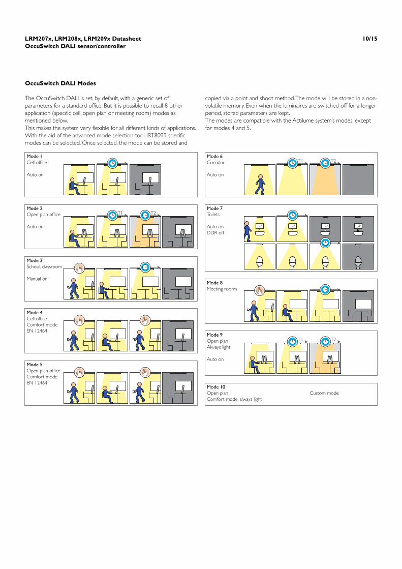
The OccuSwitch DALI is set, by default, with a generic set of parameters for a standard office. But it is possible to recall 8 other application (specific cell, open plan or meeting room) modes as mentioned below.This makes the system very flexible for all different kinds of applications. With the aid of the advanced mode selection tool IRT8099 specific modes can be selected. Once selected, the mode can be stored and
copied via a point and shoot method. The mode will be stored in a non-volatile memory. Even when the luminaires are switched off for a longer period, stored parameters are kept.The modes are compatible with the Actilume system’s modes, except for modes 4 and 5.
T1 T2
T1 T2
T1 T2
Mode 1Cell of�ce
Auto on
Mode 3School, classroom
Manual on
Mode 5Open plan of�ceComfort modeEN 12464
Mode 2Open plan of�ce
Auto on
Mode 4Cell of�ceComfort modeEN 12464
Mode 6Corridor
Auto on
Mode 7Toilets
Auto onDDR off
Mode 10Open planComfort mode, always light
Custom mode
Mode 8Meeting rooms
Mode 9Open planAlways light
Auto on

LRM207x, LRM208x, LRM209x DatasheetOccuSwitch DALI sensor/controller
11/15
M
ode
App
licat
ion
Occ
upan
cy
Smar
t tim
er
Back
grou
nd p
erio
d D
aylig
ht o
verr
ide
Day
light
dep
ende
nt
Day
light
dep
ende
nt
Para
llel l
ink
peri
od
(m
inut
es)
(min
utes
)
regu
latio
n sw
itchi
ng
(Adv
ance
d on
ly)
1
Cel
l offi
ce (
defa
ult)
A
uto ON
/OFF
10
0
Win
dow
onl
y W
indo
w /
corr
idor
W
indo
w o
nly
Loca
l occ
upan
cy
2
Ope
n pl
an o
ffice
A
utoON
/OFF
10
12
0 W
indo
w o
nly
Win
dow
/ co
rrid
or
Win
dow
onl
y Lo
cal o
ccup
ancy
3
Cla
ss r
oom
M
anua
lON
/aut
o O
FF10
0N.a.
Windo
w/corridor
Windo
w/corridor
Localo
ccupancy
4
Cello
ffice*
Disabled
10
0N.a.
Windo
w/corridor
Windo
wonly
N.a.
5
Openplan*
Disabled
10
0N.a.
Windo
w/corridor
Windo
wonly
N.a.
6
Cor
ridor
A
utoON
/OFF
10
60
W
indo
w /
corr
idor
W
indo
w /
corr
idor
W
indo
w /
corr
idor
Lo
cal o
ccup
ancy
7
Toile
ts
Aut
oON
/OFF
0
15 (
port
al o
nly)
D
isabl
ed
Disa
bled
D
isabl
ed
Loca
l occ
upan
cy
8
Mee
ting
room
M
anua
lON
/aut
o O
FF
10
0 D
isabl
ed
Win
dow
/ co
rrid
or
Win
dow
onl
y Lo
cal o
ccup
ancy
9
Ope
n pl
an o
ffice
**
Aut
oON
/OFF
10
In
finite
W
indo
w o
nly
Win
dow
/ co
rrid
or
Win
dow
onl
y Ba
ckgr
ound
ligh
ting
10
Custom
N.a.
N.a.
N.a.
N.a.
N.a.
N.a.
N.a.
* E
qual
s m
ode
1 an
d 2,
but
with
out
MD
act
ive.
Do
not
use
thes
e m
odes
for
norm
al a
pplic
atio
ns.
** T
his
mod
e w
orks
diff
eren
tly in
the
adv
ance
d (L
RM20
80)
vers
ion.
Her
e th
e lig
hts
will
switc
h of
f (th
e ba
sic n
ever
sw
itche
s of
f) w
hen
none
of t
he a
dvan
ced
Occ
uSw
itch
DA
LI u
nits
in t
he p
aral
lel n
etw
ork
dete
ct m
ovem
ent.
If on
e,
or m
ore,
do
dete
ct m
ovem
ent
all o
ther
uni
ts w
ill go
to
back
grou
nd le
vel.
LRM207x, LRM208x, LRM209x DatasheetOccuSwitch DALI sensor/controller
12/15
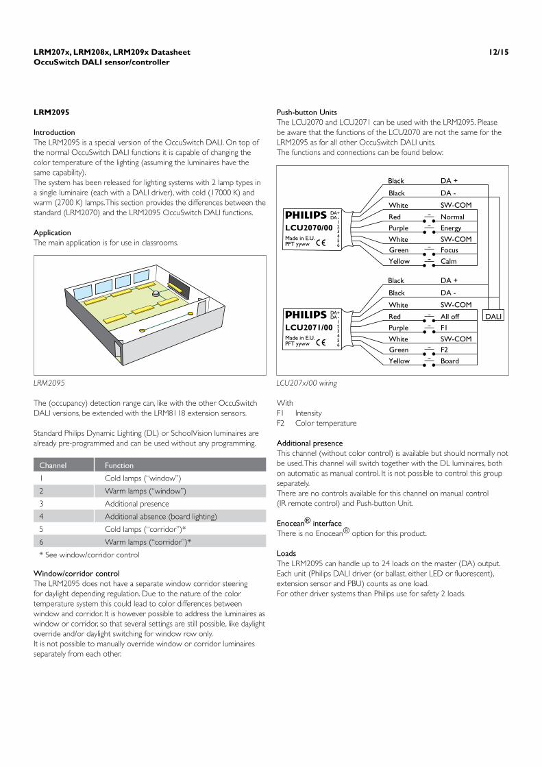
LRM2095
IntroductionThe LRM2095 is a special version of the OccuSwitch DALI. On top of the normal OccuSwitch DALI functions it is capable of changing the color temperature of the lighting (assuming the luminaires have the same capability).The system has been released for lighting systems with 2 lamp types in a single luminaire (each with a DALI driver), with cold (17000 K) and warm (2700 K) lamps. This section provides the differences between the standard (LRM2070) and the LRM2095 OccuSwitch DALI functions.
ApplicationThe main application is for use in classrooms.
The (occupancy) detection range can, like with the other OccuSwitch DALI versions, be extended with the LRM8118 extension sensors.
Standard Philips Dynamic Lighting (DL) or SchoolVision luminaires are already pre-programmed and can be used without any programming.
Window/corridor controlThe LRM2095 does not have a separate window corridor steering for daylight depending regulation. Due to the nature of the color temperature system this could lead to color differences between window and corridor. It is however possible to address the luminaires as window or corridor, so that several settings are still possible, like daylight override and/or daylight switching for window row only.It is not possible to manually override window or corridor luminaires separately from each other.
Push-button UnitsThe LCU2070 and LCU2071 can be used with the LRM2095. Please be aware that the functions of the LCU2070 are not the same for the LRM2095 as for all other OccuSwitch DALI units.The functions and connections can be found below:
WithF1 IntensityF2 Color temperature
Additional presenceThis channel (without color control) is available but should normally not be used. This channel will switch together with the DL luminaires, both on automatic as manual control. It is not possible to control this group separately.There are no controls available for this channel on manual control (IR remote control) and Push-button Unit.
Enocean® interfaceThere is no Enocean® option for this product.
LoadsThe LRM2095 can handle up to 24 loads on the master (DA) output. Each unit (Philips DALI driver (or ballast, either LED or fluorescent), extension sensor and PBU) counts as one load.For other driver systems than Philips use for safety 2 loads.
LRM2095
Black
Black
White
Red
Purple
WhiteGreen
Yellow
SW-COM
DA -
DA +
Normal
Energy
SW-COMFocus
Calm
LCU2070/00Made in E.U.PFT yyww
DA+DA-
123456
Black
Black
White
Red
Purple
WhiteGreen
Yellow
SW-COM
DA -
DA +
All off DALI
F1
SW-COMF2
Board
LCU2071/00Made in E.U.PFT yyww
DA+DA-
123456
LCU207x/00 wiring
Channel Function
1 Cold lamps (“window”)
2 Warm lamps (“window”)
3 Additional presence
4 Additional absence (board lighting)
5 Cold lamps (“corridor”)*
6 Warm lamps (“corridor”)*
* See window/corridor control

LRM207x, LRM208x, LRM209x DatasheetOccuSwitch DALI sensor/controller
13/15
Remote controlThe LRC2095 can be used with standard Philips IR remotes, like the other OccuSwitch DALI units. There are some difference though.•DonotuseIRchannel2and3• UseIRchannel1tocontrolthemainlighting(intensityonly)• UseIRchannel5tocontroltheboardlighting.
The IRT7090 can be used as well for the standard luminaires (no option available for board lighting, a separate control (eg. IRT8050) is required.
User InterfacesThere are several user interface options available for this product. Refer to the SchoolVision propositions for more details.
Calibration(see also commissioning guide)
IRT8096The IRT8096 is a specific tool for SchoolVision. It can set the required light level and change Preset1 (normal) to another value than 300 Lux.
Operation of the IRT8096General light level calibrationStep 1 Select (preset) 3Step 2 Change the light level with the arrows to the
required light level, for SchoolVision this will be 1000 Lux.
Step 3 Press Save3, the lights will blink to confirm that the setting has been accepted and stored.
Change“Normal”(preset1)to500LuxStep 1 Select (preset) 1Step 2 Change the light level with the arrows to the
required light level, for instance to 500 Lux.Step 3 Press Save1, the lights will blink to confirm that the
setting has been accepted and stored.
IRT7090
1
3
2
4
1 3
Save1
Save3
0
IRT8096
SafetyThe OccuSwitch DALI uses DALI or DALI like signals to communicate to other devices, ballasts or BMS systems. The interfaces (DA and X) on the OccuSwitch DALI are supplementary isolated from mains (SELV). However most DALI devices (like ballasts in luminaires) only provide basic isolation between mains and DALI. Therefore to avoid Installation safety Issues all interface wiring (also on the X-Interface) should be treated as FELV, so mains rated isolation is required.We strongly recommend to always use cabling with mains rated isolation to prevent potential unsafe installations.
Short circuit and protectionThe DA (all units) and X (LRM207x and 208x) interface provides DALI (or other) power in order to be able to communicate. These interfaces are protected against a short circuit if used within specification.External power (DALI) supplies can only be used on the BMS DALI network of the LRM209x (X-Interface).The use of more than 22 LRM208x units in parallel connected on the X-Interface can damage the X-Interface circuit.The network (X) interface of the LRM209x Is extended protected against mains connection. For all OccuSwitch DALI devices the DA and X interface (except X-Interface on LRM209x) will be damaged beyond repair if mains power is connected. Although safe, smoke and a strong smell can occur if this happens.
Parallel modeThe LRM208x OccuSwitch DALI advanced supports parallel mode for occupancy control (X-interface). This means that the separate units have their own daylight depending and local control and their own settings. Only the MD signal from connected units is shared. This means that lights will stay on if one of the connected systems detects movement. Lights will stay on and only switch off, or go to background level when the last MD timer in the group elapses.Exception to this rule is mode 9. The parallel link is refreshed every 60 seconds. So when movement is detected a signal will be given, than after 60 seconds again, and again, until de timer elapses. This signal is visible on the unit.

LRM207x, LRM208x, LRM209x DatasheetOccuSwitch DALI sensor/controller
14/15
Technical data
Environmental conditionsStorage conditionsTemperature -20 .. +70 ºCRelative humidity 10 to 85 %; no condensationOperating conditionsTemperature +5 .. +50ºCRelative humidity 15% to 80%; no condensation
Mains connectionVoltage 230VAC +/10%; 50/60HzPower consumption Stand-by <1 W (without DALI load) Max. 1.7 W (with 15 ballasts) LRM20x1 (Enocean® option) adds 0.2WConnector screw terminal MRT3P7.62-3VE or GMVSTBW2.5/3-ST-7.62Wire range 0.75 .. 2.5 mm2
Note wires must be >= 0.75 mm2
Mainsdistributionsystem TN-S,16Amax,withNeutral groundedInterfacesParallel interface (LRM208x only) Up to 22 units in parallel Free topology wiring and polarity sensitiveBMS interface (LRM209x only) DALI compatible Up to 64 units in parallel (depending on control device used as master) Free topology and polarity insensitive
DALI output interfaceProtocol Bi phase coded according to EN60929ExtendannexE Networkpolarityandpolarity insensitiveLoad capacity Maximum 15 DALI devices per output (for LRM207x X+DA Interface)
Protection Interface is short circuit proofTransmission rate Max. 1200 bits per secondDALI voltage 11.5VDC to 21.5VDCConnector type Wieland BST 14i2; blueGeneralLED indicators see textSwitch off delay 1,5,10,15,20,25,30,35* minutes * OmniProg onlyLight levels 250 .. 1000 Lux (30% reflection)Detection range see detection pattern, page 4 (IR remote is similar)Light sensor see diagram, page 4
Standards EN/IEC61347-2-11Lampcontrol gear, Particular requirements for miscellaneous electronic circuits used with luminaires IEC 60598-1 Luminaires, General requirements and testsClassification Class IPollution degree 2Over voltage category IIIApprobation Product complies with the relevant European Directive (CE) KEMA ENECProtection Class IP20Flammability UL94 V-0Glow wire test 960°C/5sInsulation Supplementary insulation between Mains and SELVEMCComplianceIEC (EN)61347-2-11/60598-1ImmunityIEC (EN)61547EmissionIEC (EN)55015andIEC(EN)55022, class B

LRM207x, LRM208x, LRM209x DatasheetOccuSwitch DALI sensor/controller
15/15
3222 636 3320310/2010Data subject to change
www.philips.com/lightingcontrols
Packing dataType Box dimensions Qty Material Weight (Kg) (mm) net grossLRM2070/10 105 x 95 x 58 1 card board 0.12 0.15LRM2071/10 105 x 95 x 58 1 card board 0.18 0.21LRM2080/10 105 x 95 x 58 1 card board 0.12 0.15LRM2081/10 105 x 95 x 58 1 card board 0.18 0.21LRM2090/10 105 x 95 x 58 1 card board 0.12 0.15LRM2091/10 105 x 95 x 58 1 card board 0.18 0.21LRM2095/00 105 x 95 x 58 1 card board 0.12 0.15LCC2070 - 1 plastic bag 0.13 0.14LCC2080 - 1 plastic bag 0.13 0.14LRH2070 105 x 95 x 58 1 card board 0.05 0.08LCU2070 - 1 plastic bag 0.16 0.21LCU2071 16 x 11 x 0.5 1 plastic bag 0.16 0.21IRT8097 131 x 58 x 87 1 card board 0.06 0.09IRT8099/10 168 x 45 x 22.5 1 card board 0.08 0.10
Ordering dataType MOQ Ordering number EAN code level 1 EOCLRM2070/10 Basic 1 9137 003 32904 8711 559 732305 732305 99LRM2071/10 Basic RF 1 9137 003 33304 8711 559 732404 732404 99LRM2080/10 Advanced 1 9137 003 33004 8711 559 732343 732343 99LRM2081/10 Advanced RF 1 9137 003 33404 8711 559 732442 732442 99LRM2090/10 BMS 1 9137 003 33103 8711 559 732367 732367 99LRM2091/10 BMS RF 1 9137 003 33503 8711 559 732466 732466 99LRM2095/00 Dynamic Lighting 1 9137 003 39403 8727 900 900590 900590 00LCC2070 Wieland cable for LRM2070 1 9137 003 33703 8711 559 732497 732480 99LCC2080 Wieland cable for LRM2080-90 1 9137 003 33803 8711 559 732510 732503 99LRH2070 Surface Box 1 9137 003 33903 8711 559 732534 732527 99LCU2070 PBU 1 9137 003 35103 8727 900 870268 870268 00LCU2071 PBU opt. 1 1 9137 003 39303 8727 900 870268 870268 00IRT8097 OmniProg Easy 1 9137 003 34103 8727 900 891409 891409 00IRT8099/10 OmniProg Standard 1 9137 003 34203 8711 559 732572 732565 99