
lR;eo t;rs Hkkjr ljdkj jy e=ky;rdso.indianrailways.gov.in/works/uploads/File/450 KW us da set 7...
49
Page 1 of 49 File No. EL/ 0.6.2 / 450 KW / 7 50 KVA U-S / DA set Effective from xxx., 2017 RDSO/PE/SPEC/D/AC/0188 -2016 (Rev. “0”) Prepared by: SSE / TL-AC/ Panel & System Design-IV Checked by: Dir.TL & AC SYSTEM DESIGN lR;es o t;rs Hkkjr ljdkj js y ea =ky; GOVERNMENT OF INDIA MINISTRY OF RAILWAYS vuq la /kku vfHkdYi ,oa ekud la xBu js y ea =ky; RESEARCH DESIGNS AND STANDARDS ORGANISATION MINISTRY OF RAILWAYS Mcywñ ,yññ,yñvkjñ ,eñ ,pñ@”fDr ;ku es uhps yxs 7 50 dñsohñ,ñ@ 450 fdyksokWV ds Mhty&vYVjusVj lsV dh fof’kf"V SPECIFICATION FOR HIGH CAPACITY 750 KVA / 450 KW UNDER SLUNG DIESEL-ALTERNATOR SET FOR AC POWER CAR (WLLRMH) vkj-Mh-,l-vks - fofÓf.V lW+ [;k vkj-Mh-,l-vks -@ihbZ @fofÓf.V@³h@,lh@0188&2016 (ifj’kks /ku “0“) RDSO Specification no. RDSO/PE/SPEC/D/AC/0188-2016 (REV. “0”) S. No. Date of amendment Revision Reason 1 Sept.., 2016 Rev. “1” Due to technical requirement updates vuq eks fnr APPROVED dk;Z dkjh funs ’kd@ih ,l ,.M bZ ,e ;w ED/PS &EMU INDEX
Transcript of lR;eo t;rs Hkkjr ljdkj jy e=ky;rdso.indianrailways.gov.in/works/uploads/File/450 KW us da set 7...
Page 1 of 49 File No. EL/ 0.6.2 / 450 KW / 750 KVA U-S / DA set Effective from xxx., 2017
RDSO/PE/SPEC/D/AC/0188 -2016 (Rev. “0”)
Prepared by: SSE / TL-AC/ Panel & System Design-IV
Checked by:
Dir.TL & AC SYSTEM DESIGN
lR;eso t;rs
Hkkjr ljdkj jsy ea=ky;
GOVERNMENT OF INDIA MINISTRY OF RAILWAYS
vuqla/kku vfHkdYi ,oa ekud laxBu
jsy ea=ky; RESEARCH DESIGNS AND STANDARDS ORGANISATION
MINISTRY OF RAILWAYS
Mcywñ ,yññ,yñvkjñ ,eñ ,pñ@”fDr ;ku es uhps yxs 750 dñsohñ,ñ@ 450 fdyksokWV ds
Mhty&vYVjusVj lsV dh fof’kf"V
SPECIFICATION FOR HIGH CAPACITY 750 KVA / 450 KW UNDER SLUNG DIESEL-ALTERNATOR SET FOR
AC POWER CAR (WLLRMH)
vkj-Mh-,l-vks- fofÓf.V lW+[;k vkj-Mh-,l-vks-@ihbZ @fofÓf.V@³h@,lh@0188&2016 (ifj’kks/ku “0“)
RDSO Specification no. RDSO/PE/SPEC/D/AC/0188-2016 (REV. “0”)
S. No. Date of amendment Revision Reason 1 Sept.., 2016 Rev. “1” Due to technical requirement updates
vuqeksfnr
APPROVED dk;Zdkjh funs’kd@ih ,l ,.M bZ ,e ;w ED/PS &EMU
INDEX

Page 2 of 49 File No. EL/ 0.6.2 / 450 KW / 750 KVA U-S / DA set Effective from xxx., 2017
RDSO/PE/SPEC/D/AC/0188 -2016 (Rev. “0”)
Prepared by: SSE / TL-AC/ Panel & System Design-IV
Checked by:
Dir.TL & AC SYSTEM DESIGN
CHAPTER No. DESCRIPTION PAGE NO. CHAPTER No. 1 General description of the specification 3-13 CHAPTER No. 2 General Technical requirement of under slung DA set. 14-18 CHAPTER No. 3 Technical requirement of diesel engine. 19-26 CHAPTER No. 4 Technical requirement of alternator. 27-34 ANNEXURE -A Schedule of technical data sheet to be furnished by the
manufacturer along with the tender and type test for diesel engine
35-39
ANNEXURE -B Schedule of technical data sheet to be furnished by the manufacturer along with the tender and type test for alternator
40-42
ANNEXURE -C Schedule of technical data sheet to be furnished by the manufacturer along with the tender and type test for roof mounted radiator system.
43-44
ANNEXURE -D List of Drawings and Specifications 45 ANNEXURE -E Undertaking for cartel formation 46 ANNEXURE-F Fire retardant test 47 ANNEXURE-G F Format for quality assurance plan 48-49 ANNEXURE-H G Format for 6 months extensive running trial of diesel-alternaor set. 50

Page 3 of 49 File No. EL/ 0.6.2 / 450 KW / 750 KVA U-S / DA set Effective from xxx., 2017
RDSO/PE/SPEC/D/AC/0188 -2016 (Rev. “0”)
Prepared by: SSE / TL-AC/ Panel & System Design-IV
Checked by:
Dir.TL & AC SYSTEM DESIGN
CHAPTER -1
GENERAL DESCRIPTIONS OF THE SPECIFICATION
1.0 FOREWORD; Presently the rakes of End on Generation (EOG) trains are working on electric
power supply provided from two power cars each fitted with two DG sets of 500 KVA / 336 KW or 750 Kva/ 450 kW in high capacity power cars. Other mail express trains are having self generating coaches having alternators and inverters for power supply arrangement in coaches. HOG system of power supply is being developed in which coaches will be supplied power from Electric / Diesel Locomotive. In such case during failure of HOG system of power supply, there will be a requirement of emergency supply through diesel generator set. Such DA sets shall be mounted under- slung either in power car or in SLR, so that they can feed power through the feeder running across the train length in case of failure of HOG system. In each power car / SLR one DA set of 500 KVA / 336 KW shall be provided under-slung.
1.1 SCOPE: 1.1.1 This specification covers supply, assembly, installation, commissioning,
performance, testing requirement of under slung Diesel Alternator set of capacity 450 KW / 750 KVA, 750 V AC, 3-phase along with roof mounted modular type radiator, instrumentations, protective devices and accessories, gauges including fuel pipe line, water pipe line, engine air intake pipeline, exhaust piping etc in LDSLR / Power Car.
1.1.2 System should be in conformance with code of practice for wiring in 750 V EOG
system as per ELPS/ SPEC/ EOG/01, March 1994 1.2 SCOPE OF SUPPLY: Manufacturer / supplier shall supply the under slung Diesel-Alternator set along
with items as per Bill of Material (BOM) given in clause no. 3.13 and 4.13 . Manufacturer shall ensue that engine supplied to Indian Railways must be
complying to latest applicable CPCB norm for emission on the date of supply. 1.3 GOVERNING SPECIFICATIONS: 1.3.1 Following UIC regulations as far as they can appropriately be applied to the
coaches for Indian Railways shall be applicable: 1.3.2 The supplier shall furnish the details of all the international standards viz UIC /
ISO / IS/ IEC / DIN / EN and RDSO specifications to which the equipment shall conform.

Page 4 of 49 File No. EL/ 0.6.2 / 450 KW / 750 KVA U-S / DA set Effective from xxx., 2017
RDSO/PE/SPEC/D/AC/0188 -2016 (Rev. “0”)
Prepared by: SSE / TL-AC/ Panel & System Design-IV
Checked by:
Dir.TL & AC SYSTEM DESIGN
UIC UIC : 564-2 Regulations relating to the fire protection and the fire fighting
measures in passenger carrying railway vehicles or assimilated vehicles used on international services.
UIC : 566 Loading of coach bodies and their components UIC : 567 General conditions for coaches. IEC IEC : 60571 -1998 or latest Rules for electronic equipment used on the rail vehicles. IEC 61000 series Electromagnetic compatibility (EMC) Pt.-4, Testing and
measurement technique-section-4, Electrical test transient / burst immunity test.
IEC : 61373 Railway application – Rolling stock equipment – Shock & Vibration tests
IEC : 60349 Rotating electrical machines for rail and road vehicles. IEC : 60101 Rules for auxiliary machines on motor vehicles ISO ISO: 8528 Pt.-10 or latest ISO: 8528 Pt.-9 or latest
Reciprocating internal combustion engine driven alternating current generating sets-Part 10: Measurement of airborne noise by the enveloping surface method
Reciprocating internal combustion engine driven alternating current generating sets-Part 9: Measurement of airborne vibration by the enveloping surface method
EN EN 50141 Electromagnetic compatibility, basic immunity standard. Conducted
disturbances induced by radio frequency field. Immunity test EN 45545 Part 1 to 7-2009 Fire protection on railway vehicle British standards BS : 5514 part 1 -1996 and ISO 3046 -1 : 1995 or latest
Reciprocating Internal Combustion Engine performance Part 1 Standard reference conditions, de-ration of power, fuel and lubricating oil consumption and test methods.
BS : 5514 part 3 -1990 and ISO 3046 -3 : 1989 or latest
Reciprocating Internal Combustion Engine performance Part 3 Specification for test measurements.
BS : 5514 part 4 -1997 and ISO 3046 -4 : 1997 or latest
Reciprocating Internal Combustion Engines Part-4 speed governing.
BS : 5514 part 5 -1979 and ISO 3046 -v : 1978 or latest
Reciprocating Internal Combustion Engine performance Part 5 Torsional vibrations.
BS : 5514 part 6 -1992 and ISO 3046 -6 : 1990 or latest
Reciprocating Internal Combustion Engine performance Part 6 Specification for over speed protection.
BS : 5514 part 7 -1996 and ISO 3046 -7 : 1995 or latest
Reciprocating Internal Combustion Engine performance Part 7 Code for engine power.
Indian Standards IS:10000-1980 Pt. 9 or latest Methods of tests for internal combustion engine (Endurance test). IS :4722-2001 or latest Specification for rotating electrical machines. IS :7132-73 or latest Guide for testing synchronous machines. IS :7306-74 or latest Methods for determining synchronous machine quantities from tests. IS :4889-68 or latest Methods of determination of efficiency of rotating electrical machines. IS :1460-2005 or latest Automotive Diesel fuels. IS :13730 Part -13 1994 or latest
Particular types of winding wires Part 13 Polyester or polyesterimide over coated with polyamide enameled round copper wire, class 200.

Page 5 of 49 File No. EL/ 0.6.2 / 450 KW / 750 KVA U-S / DA set Effective from xxx., 2017
RDSO/PE/SPEC/D/AC/0188 -2016 (Rev. “0”)
Prepared by: SSE / TL-AC/ Panel & System Design-IV
Checked by:
Dir.TL & AC SYSTEM DESIGN
IS:13947-1993 Pt. 1 IS/IEC60947 or latest
Specification for low voltage switchgear & control gear–Pt. 1, General requirements.
IS : 13778-1993 Part 1 to 6 or latest
Method of test for winding wires-thermal properties.
IS: 1239 Part-2-1982 or Latest Mild Steel tubes, tubler and other wrought steel fitting, part-2 mild steel tubular and other wrought steel pipe fittings.
IS 649 Stator and rotor stamping. IS 7624 Lead acid Battery for starter battery. RDSO Specifications (Specn), Schedule Technical Requirements (STR) and Modification Sheet (MS) ELRS/ Spec / ELC/ 0019 (Rev.’2’) Feb, 2011 or latest
Thin-walled Electron beam Halogen free Irradiated Cable with copper conductors for powered rolling stock applications.
RDSO specification no. ELPS/ SPEC./ EOG/ 01
Specification and Code of practice for wiring in 750 Volts EOG system coaching stock.
RDSO specification no ELPS/ SPEC/ EOG/02 Nov., 1994.
Specification for Broad gauge High capacity power car for 750 V, EOG system.
RDSO/ PE/ SPEC/ TL/ 0001-98 (Rev-10) with amendment no. 1 issued in 17-01-2013 or latest.
Low Maintenance lead acid batteries for diesel locomotives /power car.
RDSO/ PE/ SPEC/ AC- 0138-2009 (Rev-1) or latest.
Specification of conduit system for cable management
RDSO / PE/ MS / AC / 0051-2011 (REV.”2”) or latest.
Modification sheet for provision of Head–On-Generation ( HOG) power supply system in LHB design power car and coaches
RDSO/PE/STR/ ac/ 0037-2012 (REV. “0”)
RDSO STR no. Diesel- Alternator set for power car.
ELRS/ SI / 0015 or latest RELIABILITY OF ELECTRONICS USED IN ROLLING STOCK APPLICATION, OCT 2001
Note: Latest version of the above mentioned specifications /standards shall be applicable, and shall be available for the references with manufacturer before commencing the proto type/ Acceptance / Routine / tests.
1.4 SERVICE CONDITIONS The generator sets fitted in under frame of power car shall be suitable to operate
continuously under following varying climatic conditions existing throughout India normally encountered on the Indian Rolling Stock:
1.4.1 Environmental Condition Minimum ambient temperature: - 5 ° C Maximum ambient temperature: 55° C Humidity : up to 100 % Altitude : Max.1200 meter above sea level
Atmosphere : Extremely dusty and desert weather, atmosphere with fog, synthetic dust of Brake block shoe, flying ballast etc. The
dust contents in the air may reach as high as 1.6 mg /m³.
Annual rain falls : Very heavy in certain areas between

Page 6 of 49 File No. EL/ 0.6.2 / 450 KW / 750 KVA U-S / DA set Effective from xxx., 2017
RDSO/PE/SPEC/D/AC/0188 -2016 (Rev. “0”)
Prepared by: SSE / TL-AC/ Panel & System Design-IV
Checked by:
Dir.TL & AC SYSTEM DESIGN
1750 to 6250 mm. 1.4.2 The equipment shall be designed to work in coastal area humid salt laden and
corrosive atmosphere. The maximum values of the condition shall be as under: Maximum pH value : 8.5 Sulphate : 7 mg/liter Max. Concentration of chlorine : 6 mg/liter Max. Conductivity : 130 micro semen / CM
1.4.3 Train Speed : 200 Km / hr max. 1.4.4 Vibration & Shunting Shocks The coaches are expected to run up to a maximum speed of 200 km/h in
varying climatic conditions exiting throughout India. All accessories to be mounted on the coach shall be designed to withstand service vibrations and buffing shocks.
i) Maximum vertical acceleration : 3 g ii) Maximum lateral acceleration : 3 g iii) Maximum longitudinal acceleration : 3 g (Corresponding to shunting shocks)
iv) Frequency and amplitude Sinusoidal form of vibrations, the frequency ‘f’ lies between 1 Hz and 50 Hz. And their amplitude ‘a” expressed in mm, is given as a function ‘f’ by the equations: a = 25/f for values of ‘f’ between 1 Hz and 10 Hz. And a = 250/f² for values of ‘f’ between 10 Hz and 50 Hz (“g” being the value of acceleration due the gravity)
1.4.5 The DA sets shall be mounted in the under frame of rail coach, normally subject
to vibrations. The design of equipment and their accessories shall be capable to withstand accidental shocks also due to impact.
1.4.6 Equipment and auxiliaries mounted above and below under frame shall not
cause vibration on the car floor, walls, ceiling panels, handholds or seat frames in excess of 2 mm peak to peak amplitude for the frequency range from 1.4 HZ to 20 Hz and in excess of 0.8 mm. per second peak vibration velocity for the frequency range above 20 Hz.
1.4.7 The firm shall submit the Finite Element Analysis (FEA) report of the DA set
mounting arrangement to RDSO / RCF / MCF / ICF before the prototype test to ensure the suitability for rolling stock application.
1.4.8 Diesel-Alternator set shall be design in such a manner, so that it shall work
satisfactorily under water level up to the 400 mm from the rail level on the railway track level or water proof up to bottom shaft level of DA set in fully loaded condition with worn wheel, which is lesser.

Page 7 of 49 File No. EL/ 0.6.2 / 450 KW / 750 KVA U-S / DA set Effective from xxx., 2017
RDSO/PE/SPEC/D/AC/0188 -2016 (Rev. “0”)
Prepared by: SSE / TL-AC/ Panel & System Design-IV
Checked by:
Dir.TL & AC SYSTEM DESIGN
1.5 General requirement: 1.5.1 The under slung DA set should be compact, robust and light in weight. 1.5.2 The proposal of the DA set supplier shall be acceptable after having validated
the offer by RCF / MCF / ICF validation using computer simulation etc. 1.5.3 The Firms shall make his own arrangements for welding sets, welding rods and
welders for fabrication work to be done for commissioning at site. 1.5.4 The detail of voltage regulation system shall be clearly explained with
schematic diagrams by the firm. 1.5.5 Two sets of maintenance and operation manuals shall be supplied free of cost
separately with each diesel engine and alternator of under slung DA set. 1.5.6 Details of type test, acceptance test & routine test procedure / protocol adopted
by the manufacturer shall be furnished along with tender to the purchaser as and when required by the purchaser. The RDSO / purchaser reserves the right to alter the scope, extent or content of any or all tests under each stage test being followed by the manufacturers / supplier, if considered essential for the application.
1.5.7 Once a Proto type approval for a make, type and rating of the under slung
Diesel engine and alternator has been granted, based on the prototype type test results, the design of the same shall not be changed without the specific and written approval of RDSO. In the event of any of the parameter that have a bearing on the performance, deviating from the type values, beyond the permissible tolerances, RDSO reserves the right to repeat the type tests.
1.5.8 A certificate to the effect that after sales service will be rendered for diesel
engine and alternator at all the cities where EOG trains originated / terminated i.e. Mumbai, Kolkata, New Delhi, Secundrabad, Bangaluru, Lucknow and Chennai etc. along with the name, address and telephone number of the service personnel shall be furnished. This information shall also be included in the maintenance manuals.
1.5.9 The firm shall furnish complete information as per Annexure-`A' for the diesel
engine and Annexure-`B’ for the alternator and Annexure- `C’ for Roof mounted modular type radiator along with detail design documents.
1.5.10 The firm shall furnish detailed drawings of radiator indicating the overall and
mounting dimensions and other details to facilitate installation of the radiator separately. Technical particulars about the radiator like minimum air flow required through the radiator at 55 °C ambient, its total heat rejection capacity (when new), the pressure drop across the radiator etc. shall be furnished.

Page 8 of 49 File No. EL/ 0.6.2 / 450 KW / 750 KVA U-S / DA set Effective from xxx., 2017
RDSO/PE/SPEC/D/AC/0188 -2016 (Rev. “0”)
Prepared by: SSE / TL-AC/ Panel & System Design-IV
Checked by:
Dir.TL & AC SYSTEM DESIGN
1.5.11 The electrical schematic / wiring diagram of the diesel engine with the details of components used (protections, contactors, switches, gauges etc.) clearly spelt out shall be submitted by the firm to RDSO and along with the tender documents.
1.5.12 Clause-by-clause compliance of the specification shall be furnished by the manufacturer / supplier.
1.5.13 Cables in the coach for interconnecting various equipments shall be supplied
and laid by production units. All the control and power cable shall be thin-walled e-beam irradiated copper cable as per RDSO specification No. ELRS/ SPEC/ ELC/ 0019 (REV.’3’), or latest should be of approved source / make of RDSO.
1.5.13.1 All the control and power cable used by engine and alternator manufactures for their internal wiring shall be thin-walled e-beam irradiated copper cable as per RDSO specification No. ELRS/ SPEC/ ELC/ 0019 (REV.’3’), or latest should be of approved source / make of RDSO. Prior approval of RDSO shall be taken for any other type of cable.
1.5.14 Cable shall be crimped at both ends with suitable copper lugs. Heat shrinkable PVC transparent sleeve of approved make shall be provided over all the lugs and joints so that sleeves do not dislodge.
1.5.15 Computer generated cable markers / ferules of reputed make shall be provided
for identification of cables. 1.5.16 Clearance and creepage distance shall be maintained as per IS:13947-1993 Pt. 1 IS/ IEC60947 or latest. 1.5.17 The switch board cabinet (SBC) shall be installed by the PU’s / purchaser.
However initially, the manufacturer / supplier shall associate during testing, commissioning of the under slung DA set and it’s interface with the switchboard cabinet in the power car.
1.5.18 The equipments working above 110 V supply shall be provided with danger
plate as per IS: 2551. 1.5.19 Earthing symbol plate shall be provided at all locations. 1.5.20 The DA set shall be suitable for mounting in under frame in the LHB power car /
SLR of Indian Railway.
1.5.13.2 Cable protection system provided for control and power cables used by engine and alternator manufactures for their internal wiring shall be RDSO/ PE/SPEC/AC/138-2009(REV “0”) or latest for conduit system for cable management should be of approved source / make of RDSO. Prior approval of RDSO shall be taken for for any other type of conduits/fittings.

Page 9 of 49 File No. EL/ 0.6.2 / 450 KW / 750 KVA U-S / DA set Effective from xxx., 2017
RDSO/PE/SPEC/D/AC/0188 -2016 (Rev. “0”)
Prepared by: SSE / TL-AC/ Panel & System Design-IV
Checked by:
Dir.TL & AC SYSTEM DESIGN
1.5.21 Electronic components, if used, in Diesel Engine or alternator or elsewhere shall be in compliance of RDSO specification no ELRS/ SI/ 0015 OCT 2001, IEC: 60571, 2006 or latest and IEC: 61000 series shall be followed.
1.5.22 The under slung DA set shall have protection against open circuit and short
circuit of the cable and circuits used. 1.5.23 The ratio of rating to loading for electronic components used in Diesel Engine or
alternator or elsewhere to the worst working conditions shall be more than two. The firm shall submit the rating versus loading chart for the various components used corresponding to the loading at the worst working conditions and all the PCBs, if used, will be of Epoxy Resign Glass Fiber fabric.
1.5.24 The under slung diesel alternator set is also capable to work on 10 % over-load of the rated load for one hour under service conditions prescribed above.
1.6 GUARANTEE / WARRANTY 1.6.1 Guarantee / Warranty obligation of the equipment shall be as per IRS condition
of contract. 1.6.2 The supplier shall be responsible for carrying out all the modifications at his cost
on any part of the equipment during the period of warranty required for satisfactory operation of the equipment as per technical specification. For any technical decision the final authority from the purchaser’s side is RDSO.
1.6.3 All the replacements and repairs that the purchaser shall call upon the
manufacturer/supplier to deliver or perform under this guarantee shall be delivered promptly and satisfactory.
1.7 INFRINGEMENT OF PATENT RIGHTS / ISO 9000 ACCREDITATION: 1.7.1 Indian Railways shall not be responsible for infringement of patent rights arising
due to similarity in design, manufacturing process, use of similar components in the design, development of the under slung Diesel engine / Alternator and any other factor not mentioned herein which may cause such a dispute. The entire responsibility to settle any such disputes/matters lies with the manufacturer/ supplier.
1.7.2 Detail / design/documents given by the manufacturer / supplier shall not be
infringing any IPR and they are responsible in absolute and full measure instead of Railways for any such violations. Data, specifications and other IP as generated out of interaction with railways shall not be unilaterally used without the consent of RDSO and rights of Railways / RDSO on such IP is acceptable to them.

Page 10 of 49 File No. EL/ 0.6.2 / 450 KW / 750 KVA U-S / DA set Effective from xxx., 2017
RDSO/PE/SPEC/D/AC/0188 -2016 (Rev. “0”)
Prepared by: SSE / TL-AC/ Panel & System Design-IV
Checked by:
Dir.TL & AC SYSTEM DESIGN
1.8 ISO 9000 Accreditation 1.8.1 The firm seeking RDSO’s approval for manufacture and supply of under slung
Diesel Alternator set conforming to this Specification shall have ISO: 9000 accreditation or equivalent certification to ensure its conformance to Quality Systems laid down in the standard for design, manufacturing processes, raw material, testing, quality control at different stages.
1.9 CARTEL FORMATION 1.9.1 The firms will not engage cartel formation with other firms and will also submit a
declaration in this regard as per Annexure-E enclosed. 1.10 MARKING & PACKING 1.10.1 The under slung Diesel – Alternator set shall be provided with suitable name
plates, on which the following shall be marked / engraved: a) Maker’s name and trade mark. b) Rated capacity of the machine (alternator/diesel engine BHP etc.) c) Voltage and current rating. d) Class of insulation. e) Weight of alternator / Diesel Engine / Radiator. f) Engine must be affixed with a conformance label meeting the following
requirements i. Statement that “this engine conforms to the environment (protection) rule
1986”. ii. Type approval certificate number.
The label shall be affixed on part necessary for normal operation of the engine and not normally requiring replacement during the life of the engine.
1.10.2 The serial number of the machine shall be marked/ engraved/ embossed as
under:- First two digits : Year of manufacture Next two digits : Month of manufacture Next two / four digits: No. of machine manufactured in the particular month e.g. Serial No.08 02 0001 denotes machine manufactured in February 2008 with serial number of 0001
1.10.3 The equipment and its sub assembly shall be packed with wooden box of
sufficient strength or suitable metallic skid material and the empty space shall be filled with suitable filling material.
1.10.4 Manufacture shall provide a screen-printed schematic diagram of power and
control circuit at suitable place in the control panel room. 1.10.5 Manufacturer shall provide printed Do’s and Don’ts Do’s.

Page 11 of 49 File No. EL/ 0.6.2 / 450 KW / 750 KVA U-S / DA set Effective from xxx., 2017
RDSO/PE/SPEC/D/AC/0188 -2016 (Rev. “0”)
Prepared by: SSE / TL-AC/ Panel & System Design-IV
Checked by:
Dir.TL & AC SYSTEM DESIGN
1.11 TRAINING 1.11.1 The firm shall arrange for training to IR personnel in maintenance and trouble
shooting of the system supplied. Ten man-days training in operation, maintenance, & trouble shooting aspects will be provided. The supplier will provide detailed technical write-up to all the trainees. The syllabus for training will have to be approved by the user/ purchaser. The venue of training will be mutually agreed. Suitable training material will be supplied to the participants. Training will be arranged free of cost.
1.12 LIST OF SPARES AND SPECIAL TOOLS The Firms shall submit recommended list of spares for diesel alternator set and
list of special tools if required any. 1.13 DOCUMENTATION 1.13.1 The manufacturer / supplier shall submit the following information apart from
the details as per Annexure A, B, & C with the offer of type testing, in printed form and digital format and complied in a booklet. Offer of type testing with incomplete information may not be considered. Before offering for type test, Manufacturer shall furnish the following: a) System design, Salient features of the offered system, Schematic
Circuit, Functional description and Protection scheme. b) BOM (bill of Material), Data sheets for all components/devices and other
equipment proposed for use in DA Set of Power car/SLR. c) Clause by clause compliance of the specification and compliance of
drawings mentioned in Annexure D. d) Recommended list of spares. e) List of special tools, jigs and fixtures needed for assembly, testing,
commissioning, maintenance and repair. Spares catalogue. f) ISO 9000 certification. ISO certification should be from NABCB accredited
body. g) QAM (Quality Assurance Manual) and QAP (Quality Assurance Plan)
with traceability diagram. h) Test protocol with procedure of testing. i) The supplier shall supply the write up and the elaborate manual for
maintenance and troubleshooting free of cost to IR for easy maintenance. j) Operating and troubleshooting manual. k) Pre-commissioning check list. l) Sub- Vendor list for sub-systems m) Details of calibration of all measuring equipments to be used during the
testing. Valid Calibration from NABL or govt. approved laboratory shall be compulsory before starting the test.
n) Details of technical support and training offered.
Page 12 of 49 File No. EL/ 0.6.2 / 450 KW / 750 KVA U-S / DA set Effective from xxx., 2017
RDSO/PE/SPEC/D/AC/0188 -2016 (Rev. “0”)
Prepared by: SSE / TL-AC/ Panel & System Design-IV
Checked by:
Dir.TL & AC SYSTEM DESIGN
1.13.2 The Firms shall submit recommended list of spares for under slung diesel alternator set and list of special tools if required any and quote separately along with the list for both individually.
1.13.3 Design details, Circuit diagrams and detailed drawings along with isometric
view, soft copy of drawings in auto cad should also be given along with hard copy with offer by manufacturer.
1.13.4. Diesel engine documents
a) General description of diesel engine with the list of protection devices, gauges, and sensors.
b) Heat balance diagram and heat load calculation. c) Lube oil circulating diagram. d) Roof mounted radiator water circulating diagram . e) Detailed Overall General Arrangement (OGA) drawing of radiator indicating
the mounting supports of the radiator. f) Details of Electronic Control Unit (EECU) indicating electronic governor
circuit diagram. g) Anti vibration mounting design details with calculation. h) Starter battery selection calculation. i) De-ration calculation for engine BHP at site conditions. j) Any other detail of design relevant.
1.13.5 Alternator documents
a) Diagram of electrical connections together with assembly drawing showing full particulars of stator and field windings, dimensions, shape, size and numbers of turns, sections, weight and length per coil.
b) Part drawings with full details of tolerances of dimensions, finish, and material specification.
c) Circuit diagram of AVR. d) Shaft stress calculation. e) Bearing life and lubrication interval calculation. f) Insulation scheme. g) Diode selection calculation. h) Any other design related details.
1.14 QAP TO BE FOLLOWED DURING MANUFACTURING FOR DIESEL-
ALTERNATOR SET: 1.14.1 Manufacturer should comply the format for Quality Assurance Plan as per ANNEXURE–G. 1.14.2 All materials & workmanship shall be of good quality. 1.14.3 Since the quality of the equipment bears a direct relationship to the
manufacturing process and the environment under which it is manufactured,

Page 13 of 49 File No. EL/ 0.6.2 / 450 KW / 750 KVA U-S / DA set Effective from xxx., 2017
RDSO/PE/SPEC/D/AC/0188 -2016 (Rev. “0”)
Prepared by: SSE / TL-AC/ Panel & System Design-IV
Checked by:
Dir.TL & AC SYSTEM DESIGN
the manufacturer shall ensure Quality Assurance Program of adequate standard.
1.14.4 Validation and system of monitoring of QA procedure shall form a part of
type approval. 1.14.5 The material purchased from outside agencies shall conform to the relevant
Standard / Specification as specified in RDSO / IS Specification. The certificate conforming to RDSO / IS Specification should also be made available for each lot of machines. It is also preferred that in-house test facilities for purchased items should be developed by the firm so that testing of these materials can be done within the factory premises so that as check can be exercised by the Inspecting Authority in case necessary, otherwise, the testing of these materials should be done by NABL accredited Testing Agency.
1.14.6 Manufacturer/ Supplier shall submit all the technical documents i.e drawings,
design calculation, layouts, circuit diagrams etc in soft copy as well. 1.15 NOISE LEVEL MAPPING 1.15.1 Firm shall carry out noise level mapping for one proto type Power Car / SLR
with under-slung DA set as method prescribed in ISO : 8528 Pt- 10 Figure-4 at the first time of commissioning test and at the platform of the railway station .
1.16 SCHEDULE OF TECHNICAL REQUIREMENT (STR) 1.16.1 Schedule of technical requirement for this assembly of under slung DA set shall be confirmed of RDSO/ PE/ STR/ AC/ 0037-2012 (Rev. “0”).

Page 14 of 49 File No. EL/ 0.6.2 / 450 KW / 750 KVA U-S / DA set Effective from xxx., 2017
RDSO/PE/SPEC/D/AC/0188 -2016 (Rev. “0”)
Prepared by: SSE / TL-AC/ Panel & System Design-IV
Checked by:
Dir.TL & AC SYSTEM DESIGN
CHAPTER -2
TECHNICAL REQIREMENT OF UNDER SLUNG DA SET
2.0 DESCRIPTION 2.1 Diesel Alternator Set 2.1.1 The under slung Diesel alternator set shall consist of approved make diesel
engine coupled with a approved make alternator both mounted on suitable common base frame.
2.1.2 The under slung Diesel Alternator set shall generally conform to the details
indicated below: 2.1.2 The under slung Diesel Alternator set shall generally conform to the details
indicated below: a) System Details Output Power of DA set: Minimum 450 KW at 0.8 pf, 55° C & 200 meter altitude Output Power of diesel engine: Minimum 650 BHP at 55° C Output Power of Alternator : Minimum 750 KVA at NTP System Voltage, Frequency & Pf: 750 V, AC, 3-Ø 4 wire, 50 Hz ± 3 % & 0.8 b) Dimensional and weight details
i) Diesel alternator set without radiator (Max.)
3307 mm (Length) x 1927 mm (Width) x 900 mm (Height) Weight of Diesel engine & Alternator = 2200 2400 Kgs. + 2150 2400 Kgs (Approx.) Total weight of Diesel engine & Alternator = 4350 4800 Kgs (Approx.)
Weight = 1700 Kgs. (Approx.) ii) Overall Dimensions of Roof mounted Modular dish type Radiator Assy. Max.):
Length 3400 mm x Width 2500 mm x Height 700 mm, Weight = 1700 Kgs. (Approx.) 2.1.3 The Diesel alternator set shall be capable of developing the electric power of
minimum 450 KW, 750 V, 3-phase at 0.8 pf, 55° C ambient temperature and at an altitude of 200 meter. In addition the system shall have 10 % overload capacity for one hour in every 12 hrs. of continuous working.
2.1.4 It shall be possible to be accommodating the Diesel-Alternator set in under
frame portion of Power Car / SLR within the maximum moving dimensions as per RDSO Carriage Directorate EDO:590. The minimum clearance of 102 mm of DA set from rail level should be maintained with worn wheels in fully loaded conditions.

Page 15 of 49 File No. EL/ 0.6.2 / 450 KW / 750 KVA U-S / DA set Effective from xxx., 2017
RDSO/PE/SPEC/D/AC/0188 -2016 (Rev. “0”)
Prepared by: SSE / TL-AC/ Panel & System Design-IV
Checked by:
Dir.TL & AC SYSTEM DESIGN
2.2 Anti-vibration mounting 2.2.1 Suitable anti-vibration mountings of proven design with cast steel top bearing
plate as recommended by the supplier shall be provided between the mounting base frame and the coach under frame at mounting location to absorb the continuous vibrations and shocks encountered during service. AVM shall be of Dunlop or Resistoflex / Trelleborg make preferably.
2.2.2 The supplier shall furnish the design calculation for the base frame together
with selection of AVMs before fabrication to achieve following conditions: 2.2.3 “In stationary conditions as installed in the coach, when the diesel alternator set
is running from no load to full load, the vibration level measured shall be on the alternator / engine body (bearing region) and base frame" (Refer compliant to ISO: 8528-9 or latest.)
2.3 TESTS AND PERFORMANCE 2.3.1 GENERAL REQUIREMENTS
(a) Under slung DA set prototype test will be carried out by officials of RDSO at the works of the manufacturer. After successful type testing and commissioning of under slung DA set on power car, it will put under extensive field trials for six months.
(b) All type tests mentioned in table A & B in clause 3.11 and 4.11.2 shall be
carried out on Diesel engine and Alternator separately and endurance / combined test as per requirement by RDSO at the works of the manufacturer / supplier.
(c) Any defect noticed / design improvement found necessary as a result of these tests/trials shall be carried out by the manufacturer in the least possible time.
(d) All the modifications carried out in the first type tested unit after field trials shall be incorporated without any extra cost.
(e) Separate type, routine and acceptance test for DA sets will be conducted.
Proto type test will be conducted by RDSO on one DA set in accordance with specifications applicable mentioned in the table given in table A & B of clause 3.11 and 4.11.2 to verify that product meets the design and performance requirement of the specification. Some or all type test may be repeated after a period of three years to confirm the quality of the product to meet the specified requirement. Any additional test can be imposed by RDSO as per requirement in each stage.

Page 16 of 49 File No. EL/ 0.6.2 / 450 KW / 750 KVA U-S / DA set Effective from xxx., 2017
RDSO/PE/SPEC/D/AC/0188 -2016 (Rev. “0”)
Prepared by: SSE / TL-AC/ Panel & System Design-IV
Checked by:
Dir.TL & AC SYSTEM DESIGN
2.3.2. CHANGE OF DESIGN 2.3.2.1 No design change shall be undertaken by manufacturer of the diesel engine,
alternator any part of the DA set after type test without prior approval of RDSO. 2.3.2.2 Firm will not change any scheme and approved BOM without seeking prior
approval from RDSO. 2.3.3 PROTO TYPE TEST 2.3.3.1 Manufacturer shall do the type test to be witnessed by RDSO either totally or
in part on Diesel engine / Alternator or complete DA set with some special tests given in the governing specification as per clause 3.11 and 4.11.2 declared as a type test under the following conditions without any additional cost. a. A manufacturer undertakes to manufacture for the first time. b. A fundamental change in design is introduced. Modification of equipment
likely to affect its function. c. Failure or variations established during type test. d. Resumption of production after an interruption of more than two years. e. Specification is amended or revised.
Only one complete system shall be tested for this purpose. The system shall successfully pass all the type tests for proving conformity with this specification. If any one of the equipment fails in any of the type tests, the purchaser or his nominee at his discretion, may call for another equipment / card(s) of the same type and subject it to all tests or the test(s) in which failure occurred. No failure shall be permitted in the repeat test(s).
2.3.3.2 The firm shall arrange to have the complete power pack at least one DA set
demonstrated for all functional requirements on its shop floor prior to approval for dispatch and create the mockup (combined testing) for combined performance and other testing in the assembled hanging conditions similar to the mounting arrangement provided in the coach under frame. For the noise level mapping and vibration test as per ISO: 8528 Part-10 and ISO: 8528 Part-9 or latest respectively on one complete DA set.
2.3.3.3 The performance of the alternator and diesel engine shall be tested at the rating
corresponding to NTP conditions during type, acceptance and routine tests and will be equated at site condition.
2.3.4 Acceptance test 2.3.4.1 After approval of type test, all acceptance tests mentioned on in table A & B in
clause 3.11 and 4.11.2 shall be carried out on DA set (Diesel engine / alternator) by an inspecting authority nominated by the purchaser at the works of the manufacturer as mutually agreed between purchaser and manufacturer.

Page 17 of 49 File No. EL/ 0.6.2 / 450 KW / 750 KVA U-S / DA set Effective from xxx., 2017
RDSO/PE/SPEC/D/AC/0188 -2016 (Rev. “0”)
Prepared by: SSE / TL-AC/ Panel & System Design-IV
Checked by:
Dir.TL & AC SYSTEM DESIGN
2.3.5 Routine test 2.3.5.1 Routine tests mentioned in table A & B in clause 3.11 and 4.11.2 shall be
carried out on each DA set (Diesel engine / alternator) by the manufacturer at his premises to ensure compliance with the specification and the drawings.
2.3.6 Commissioning tests 2.3.6.1 These tests are to be conducted after commissioning of DA sets in Power car at
production units. These tests shall be comprised of following:- a) 100 % or full load test at specified BHP of engine and KVA of alternator for
minimum of 3 hours. b) Noise level measurement inside and outside of the coach for first proto type
DA set power car. c) Power and control connection sequence test (tabulation to be made) d) Checking of specified bill of material as per specification e) Tuning of Engine RPM and Engine and Alternator alignment f) Vibration level at base rail, diesel engine, alternator, and roof mounted dish
modular type radiator including at different locations of the coach floor with the help of strain gauges/ transducers for first proto type DA set power car.
g) Insulation resistance (IR) test. h) Phase sequence test. i) Functional / operational aspects of each sub-component as well all protections test and electrical interface shall be carried out with power control
panel. j) Checking of sealing of Roof mounted Radiators / radiator fan / Fresh air
filter and proper tightening of screws etc. and mechanical interfaces. k) Visual inspection and checking quality of workmanship.
Firm shall make complete booklet of these test conducted on first power car jointly signed with concerned Electrical Production unit and shall send the commissioning report to RDSO. For other series DA set it should be submitted to CEE of PU’s.
2.3.6.2 The alternator and diesel engine shall be tested at ambient condition. However,
the test result shall be extrapolated to on site condition to check the compliance to declared parameters.
2.3.7 FIELD TRIAL 2.3.7.1 After successful type testing and commissioning of under slung DA set on
power car, it will put under extensive field trial for six months. The report of the field trial will be submitted by zonal railway to RDSO as per Annexure-H. Firm should associate themselves for monitoring of parameters of engine etc. during field trial.

Page 18 of 49 File No. EL/ 0.6.2 / 450 KW / 750 KVA U-S / DA set Effective from xxx., 2017
RDSO/PE/SPEC/D/AC/0188 -2016 (Rev. “0”)
Prepared by: SSE / TL-AC/ Panel & System Design-IV
Checked by:
Dir.TL & AC SYSTEM DESIGN
2.4 APPROVAL OF SOURCES BY RDSO 2.4.1 Approval of sources / renewal or registration shall be granted as per approved
vendor procedure of RDSO. 2.4.2 The manufacturer shall provided and arrange all facilities to RDSO for
conducting the type tests as per Clause 3.12.1 3.11 & 4.11.2 4.10.4. In case it is necessary to conduct any of the type tests at a testing house / institution, the full cost of such tests shall be borne by the manufacturer.

Page 19 of 49 File No. EL/ 0.6.2 / 450 KW / 750 KVA U-S / DA set Effective from xxx., 2017
RDSO/PE/SPEC/D/AC/0188 -2016 (Rev. “0”)
Prepared by: SSE / TL-AC/ Panel & System Design-IV
Checked by:
Dir.TL & AC SYSTEM DESIGN
CHAPTER 3 TECHNICAL REQUIREMENT OF UNDER SLUNG DIESEL ENGINE
3.0 DIESEL ENGINE: 3.0.1 The Diesel engine shall be of robust and reliable design, turbo charged, water-
cooled and suitable for mounting in under frame of Power Car / SLR. Engine shall be able to deliver power for getting minimum electrical power output from alternator of 336 450 kW at site condition of 55o C and 200 m altitude at 1500 RPM. Firm shall declare the BHP rating of the engine at standard reference condition as per BS : 5514 Pt-I i.e at total barometric pressure of 100 kPa, ambient air temperature of 25o C, Relative Humidity of 30 % and charge air coolant temperature of 25o C. Accordingly, deration curve if any, shall also be submitted. Engine shall be capable to work on 110 10 % overload for one hour in 12 hour period of operation.
3.0.2 The engine shall also be supplied with suitable capacity of roof mounted
radiator, radiator fan, circulating water pump, lubricating oil heat exchanger, lubrication oil / fuel pump, interconnecting pipes, silencers, and exhaust pipes.
3.0.3 Manufacturer shall ensure that engine supplied to Indian Railways must be
complying with latest applicable CPCB norm for emission on date of supply. 3.1 Engine Cooling system: 3.1.1 The engine shall be water-cooled and shall be supplied with suitable capacity of
roof mounted radiator and radiator fan. The radiator shall be suitable for mounting on roof. Necessary provision with the dished roof shall be made on power car by the production units for mounting of radiator. The radiator cooling shall be done by means of suitable numbers of electrically driven fans of adequate capacity. The firm shall send the drawings of radiator assembly along with fan and motor for approval of RDSO before prototype test. The location of the radiator with respect to the coach roof and its mounting arrangement shall be finalized in consultation with Production units. The design of the radiator shall be such that it shall not infringe with the Maximum moving dimension as per RDSO Carriage Directorate drawing no. EDO: 590.
3.1.2 The manufacturer / supplier shall furnish detailed drawings of the Roof Mounted
Radiator and radiator fans indicating the overall and mounting dimensions and other details to facilitate installation of the Radiator on the roof. Technical particulars about the Radiator, like minimum air flow required through the radiator at 55° C ambient, its total heat rejection capacity (when new), the pressure drop across the radiator etc. shall also be furnished by the manufacturer/supplier.
3.1.3 The cooling equipment (Radiator, water pump, pipe lines etc.) shall be of
adequate size and capacity such that the water temperature is maintained
Page 20 of 49 File No. EL/ 0.6.2 / 450 KW / 750 KVA U-S / DA set Effective from xxx., 2017
RDSO/PE/SPEC/D/AC/0188 -2016 (Rev. “0”)
Prepared by: SSE / TL-AC/ Panel & System Design-IV
Checked by:
Dir.TL & AC SYSTEM DESIGN
within the specified range with the engine operating at the full rated load at site conditions with radiator clogged to 15 %, as the radiator being mounted on the roof , will be less vulnerable to dust clogging.
3.1.4 Charge air cooler (CAC) or any other suitable unit shall be provide to meet the
requirements of latest CPCB norms. 3.1.5 The operating range of water temperature under full load should not exceed the
maximum temperature declared by the engine manufacturer. 3.1.6 Water level indicator shall be provided at a suitable visible location, preferably in the
control panel room at roof level. One standby motor for radiator water rising motor shall also be provided.
3.1.7 Suitable capacity of water pump shall be provided in the under frame of Power
Car / SLR for water filing arrangement in the radiator. The control switch of the water pump shall be provided in on-board Panel Room.
3.1.8 The low coolant switch / indicator of reputed make with alarm shall be provided
to indicate loss of coolant during service, in roof mounted radiator. This switch shall be integrated with the safety system such that in the event of less engine coolant, the engine shall be shut off automatically by de-energizing the shut down device in order to protect the engine from any major failure.
3.1.9 The relevant drawings indicated against each of the work are for guideline
only and the Firms may study any effective improvement of the system and the firm shall submit their own drawings for RDSO approval.
3.1.11 The engine electrical wiring system (schematic) with the details of components
used (protection gears, solenoids, contactors, switches, gauges etc.). Clearly spelt out, shall be submitted by firm.
3.2 Air filter: 3.2.1 The engine shall be equipped with air filter of adequate capacity suitable for
operation in service conditions as per clause 1.4. Air filters shall not need cleaning before 1 month. The filters shall be reputed Make and shall have prior approval of RDSO.
3.2.2 The air filer location shall be selected in such a way that crew cabin staff shall
be able to check the filter condition for clogging and its attendance. To facilitate this, suitable restriction indicator will be provided.
3.2.3 The firm shall submit the drawings for general arrangement fresh air inlet to air
cleaner for approval by RDSO / PU’s.

Page 21 of 49 File No. EL/ 0.6.2 / 450 KW / 750 KVA U-S / DA set Effective from xxx., 2017
RDSO/PE/SPEC/D/AC/0188 -2016 (Rev. “0”)
Prepared by: SSE / TL-AC/ Panel & System Design-IV
Checked by:
Dir.TL & AC SYSTEM DESIGN
3.3 Fuel Pipe Line: 3.3.1 The scope of supply includes the supply and erection of seamless stainless
steel heavy duty pipes of class ‘E” conforming to IS : 1239 Part-2-1982 or latest of grade SX SS: 316 or suitable and flexible hoses of appropriate size and length with necessary pipe and end fittings, isolating cocks, union sockets etc. as needed. The exact quantity shall be as required at site. Suitable protective guard for the fuel lines shall also be provided. Design of protective guard shall be submitted to RDSO and will be approved during the commissioning of prototype Power Car.
3.3.2 Fuel tank: The power car / SLR will be provided with fuel tanks of suitable
capacity for continuous working of 50 hours, with sedimentation tank, by production units i.e. ICF / RCF / MCF. The fuel system beyond the sedimentation tank shall be in the firm scope.
3.3.3 The firm shall submit the detailed drawings for the fuel oil suction and return
pipe line from engine for approval by RDSO. 3.3.4 The firm shall submit the detailed drawings for the fuel oil suction and return
pipe line along-with Non Return Valve (NRV)from engine for approval by RDSO.
3.4 Fuel / Lube Oil: 3.4.1 The engine shall normally be required to operate on diesel fuel whose
properties shall be as per best option in IS: 1460-2005 or latest. The diesel engine shall be tested with Bharat Stage II or latest fuel oil in type test. Even though diesel engine being higher grade Bharat stage compliant, it shall be capable of operating with lower grade Bharat Stage fuel oil in case of emergency.
3.4.2 Required amount of lube oil and diesel oil for all the test during type testing and
commissioning tests shall be arranged by firm. The engine lubricating oil should be commercially available and should be of the reputed make.
3.5 Fuel Consumption meter: 3.5.1 Fuel consumption meter of a reliable and reputed make shall be provided for
monitoring the fuel oil consumption. It should be reputed make and provided in the crew cabin / control room.
3.6 Silencer: 3.6.1 The silencer shall be suitable for location on the roof of the Power Car / SLR in
dished area adjacent to the radiator exposed to atmosphere. Adequate length of the pipes, flexible pipes, elbows etc for carrying the exhaust hot gas in the silencer to the atmosphere shall be supplied and erected by the firm. Provision

Page 22 of 49 File No. EL/ 0.6.2 / 450 KW / 750 KVA U-S / DA set Effective from xxx., 2017
RDSO/PE/SPEC/D/AC/0188 -2016 (Rev. “0”)
Prepared by: SSE / TL-AC/ Panel & System Design-IV
Checked by:
Dir.TL & AC SYSTEM DESIGN
shall also be made to prevent water entry into the silencer. The exhaust pipe from manifold to the silencer shall be suitably and adequately lagged. The design shall be such as to generate the minimum noise in power car / SLR.
3.6.2 The turbocharger, exhaust pipe line manifold and the exhaust pipe lines up to
roof cutout level shall be shield type thermal clading insulation shall be provided, clad with galvanized steel sheets or aluminum sheets and firmly secured so as to ensure that there is no excessive heat in the proximity. Firm may use better alternative concept/ material with prior approval of RDSO.
3.6.3 The firm shall submit the drawings for general arrangement of silencer and
exhaust system mounting arrangement for approval by RDSO. 3.7 Electronic Governor: 3.7.1 The engine shall be supplied with or Electronic governor conforming to
International standards like BS / IEC / ISO. The governor should be suitable for transport application. Electronic Governor should be directly mounted on the engine. The firm shall also provide a suitable arrangement in the Crew compartment to facilitate varying the speed of diesel engine from idling to maximum speed at no load.
3.7.2 There should be Engine Electronic control panel (EECP) & governor for Engine
to improve regulation of RPM, frequency and monitoring of engine parameters. The device shall be easily accessible and preferably in crew area. The electronic control panel shall display the following information: a) Lubrication oil pressure b) Water temperature c) RPM of engine d) Battery voltage e) Faults / Fault code should displayed directly
It should have memory to store & access the last 50 fault codes (minimum). Firm shall give details of the system along with Overall General Arrangement (OGA) drawings & circuit diagram.
3.8 Starter Motor: 3.8.1 Diesel engine shall be equipped with a starter motor working from 24 V DC
battery supply and associated accessories like starter solenoid, fuel start Solenoid etc. for cranking the engine. The motor shall be of adequate rating to crank the engine to firing speed under the service conditions specified in Clause 1.4, without exceeding the temperature rise limits for the class of insulation.
3.8.2 The entire engine wiring shall be non-grounded. Starter motor shall be of Delco
Rammy, Lucas or any other reputed make with prior approval of RDSO.

Page 23 of 49 File No. EL/ 0.6.2 / 450 KW / 750 KVA U-S / DA set Effective from xxx., 2017
RDSO/PE/SPEC/D/AC/0188 -2016 (Rev. “0”)
Prepared by: SSE / TL-AC/ Panel & System Design-IV
Checked by:
Dir.TL & AC SYSTEM DESIGN
3.8.3 It shall not be possible to energies the starter motor, when the engine is running at speed above the minimum firing speed. Suitable cranking protection shall be provided.
3.9 Starter Battery of engine: 3.9.1 A 12 cell (3 mono blocks each comprising of 4 cells) 24 volts lead-acid battery
of 290 AH capacity to IS : 7624 (latest) or to RDSO specification shall be provided by the firm (separate for each DA sets) to feed power to the engine starter motor. The firm shall certify the adequacy of the battery. The battery shall be suitable to high discharge starting current and shall be taken from OEM directly.
3.10 Safety devices, Gauges / Sensors / Transducer / Instruments: 3.10.1 The engine shall be provided with fuel solenoid and safety devices like high
water temperature cut-out, low lube oil pressure cutout, air filter choke cutout, low water level cut out, radiator air loss cutout and over speed cutout etc. to facilitate automatic tripping of engine. The required gauges and meters shall be supplied with minimum suitable length of leads. Complete protection scheme shall be submitted to RDSO for approval.
3.10.2 The engine (DA set) being under slung mounted , the performance monitoring
control panel( remote gauges panel) shall be mounted inside the crew cabin to facilitate monitoring / starting of Diesel engine from the cabin itself. The audio and visual alarm for the fault shall also be provided in the crew cabin itself so that fault can be understood and attended promptly by cabin crew staff. The interconnecting cables, if any shall be supplied by the firm. The control panels shall also have the starting switch for operating the engine and a “STOP PUSH BOTTON “.
3.10.3 During the emergency and other failures, stopping of the engine shall be
through electronic governor actuator or through engine ECU. 3.11 TESTS ON DIESEL ENGINE: Prototype, acceptance, and routine tests as mentioned in the table given below
shall be conducted on the diesel engine at engine manufacturer premises: Table for tests on diesel engine - A
S. No.
Tests Type test
Accept-ance test
Routine test
Clause of Relevant Standard
1 Verification of dimensions of all major assemblies and sub-assemblies and weight of Diesel Engine and roof mounted radiator.
Yes Yes - As per specification

Page 24 of 49 File No. EL/ 0.6.2 / 450 KW / 750 KVA U-S / DA set Effective from xxx., 2017
RDSO/PE/SPEC/D/AC/0188 -2016 (Rev. “0”)
Prepared by: SSE / TL-AC/ Panel & System Design-IV
Checked by:
Dir.TL & AC SYSTEM DESIGN
2. i) Rating test at simulated site condition shall be conducted during the type test.
ii) The following parameters shall be made.
Clause no. 15.5.2 (Engine group-3) of BS: 5514 part-1 1996 or latest international standard. Table-5 list A test measurements S.N. A 1 to A 19, Table 7 list C and Table 8 list D CPCB certification as per the latest guidelines / norms will have to be provided by the manufacturer to substantiate the compliance of emission norms.
a) Fuel consumption rate Yes Yes Yes b) Lube oil pressure Yes Yes Yes c) Lube oil consumption Yes No No d) Cooling water inlet and
outlet temperature Yes No No
e) Exhaust gas temperature
Yes Yes No
f) Smoke test Yes Yes Yes g) Torque Yes Yes Yes h) Speed. Yes Yes Yes
3. Governing test. Yes Yes Yes BS: 5514 Part-4 1997 and ISO: 3046-4 or latest international standard.
4. Specific fuel consumption (SFC) test
Yes Yes No Clause no.15.5.2 Table 6 list B of BS: 5514 part-1 or latest international standard.
5. Endurance test
Yes No No Clause 2.1 of IS: 10000, Pt-9 after completion of initial performance test the engine shall be run for 6 cycle (each of 16 hrs. continuous running) at rated speed.
6. Roof mounted radiator capacity test (at simulated or equated at site condition 55 ° C).
Yes No No Annexure-C of this specification for reference
7 Special test i) Engine heat balance
Yes
No
No Clause no. 15.5.2 (Engine group-3) of BS : 5514 part- 1 1996 or latest International standard.

Page 25 of 49 File No. EL/ 0.6.2 / 450 KW / 750 KVA U-S / DA set Effective from xxx., 2017
RDSO/PE/SPEC/D/AC/0188 -2016 (Rev. “0”)
Prepared by: SSE / TL-AC/ Panel & System Design-IV
Checked by:
Dir.TL & AC SYSTEM DESIGN
ii) Sound Noise level mapping &
iii) Vibration test.
Yes
No
No
As per fig. 4 of ISO: 8528 part-10 As per ISO: 8528 part-9 or latest Table-5 list A test measurements S.N. A 1 to A 19 Table 7 list C and Table 8 list D
iv) Exhaust-gas emission characteristics v) Any other relevant test required by RDSO
Yes
Yes *
No
8 Environmental test on Electronic Governor and electronic control panel.
Yes
Yes No
No
IEC : 60571-2006 or latest and IEC : 61000 series or latest version
* Valid CPCB certificate to be submitted by the firm. 3.12 Bill of material: 3.12.1 The bill of materials of under slung Diesel Engine shall be as per the
details given below: S.No.
Description Quantity/Coach
1. Diesel Engine as approved by RDSO for under slung DA set application in Power Car / SLR will consist of following standard accessories:
1 set
i) Fly wheel with housing. 1 No. ii) Roof mounted radiator assembly complete with water level indicator with
tripping mechanism, radiator fans, motor frame work, fan housing, AVMs, mono-block pump for filling water in to the radiator tank, etc as per approved drawing (Refer appendix `C’).
1 set
iii) Engine coolant kit. iv) Engine air cleaner mounted on board for collecting air from the side wall
opening of the panel room of Power Car/ SLR along with the free length pipes, elbow and clamps for elbow (quantity as required at site).
1 set
v) Flexible coupling duly machined to match alternator shaft. 1 No. vi) Lube oil cooler and filter mounted on the engine. 1 No. vii) Fuel filter (Engine mounted) 1 No. viii) Corrosion resistor. As per
OEM recommen-dations
ix) Exhaust piping complete with metallic flexible pipe, rigid pipes elbows, flanges, cladding of the exhaust pipes if required, and silencer with clamps (quantity as required at site).
1 lot
x) Fuel circuit piping including seamless stainless steel pipes, flexible hoses, pipe fitting (brass), suitable size clamps to hold piping and non-return valves (as required at site).
1 lot
xi) Anti-vibration mounting pads of M/s Resistoflex / Trelleborg and mounting brackets.
1 lot
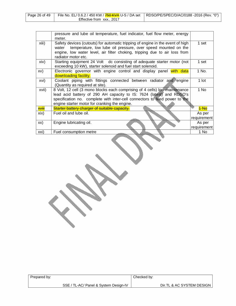
xii) Set of gauges for remote mounting on the power and control circuit panel for monitoring radiator water temperature, water level indicator, lube oil
1 set
Page 26 of 49 File No. EL/ 0.6.2 / 450 KW / 750 KVA U-S / DA set Effective from xxx., 2017
RDSO/PE/SPEC/D/AC/0188 -2016 (Rev. “0”)
Prepared by: SSE / TL-AC/ Panel & System Design-IV
Checked by:
Dir.TL & AC SYSTEM DESIGN
pressure and lube oil temperature, fuel indicator, fuel flow meter, energy meter.
xiii) Safety devices (cutouts) for automatic tripping of engine in the event of high water temperature, low lube oil pressure, over speed mounted on the engine, low water level, air filter choking, tripping due to air loss from radiator motor etc.
1 set
xiv) Starting equipment 24 Volt dc consisting of adequate starter motor (not exceeding 10 kW), starter solenoid and fuel start solenoid.
1 set
xv) Electronic governor with engine control and display panel with data downloading facility.
1 No.
xvi) Coolant piping with fittings connected between radiator and engine (Quantity as required at site).
1 lot
xvii) 8 Volt, 12 cell (3 mono blocks each comprising of 4 cells) low maintenance lead acid battery of 290 AH capacity to IS: 7624 (latest) and RDSO’s specification no. complete with inter-cell connectors to feed power to the engine starter motor for cranking the engine.
1 No
xviii Starter battery charger of suitable capacity. 1 No xix) Fuel oil and lube oil. As per
requirement xx) Engine lubricating oil. As per
requirement xxi) Fuel consumption metre 1 No

Page 27 of 49 File No. EL/ 0.6.2 / 450 KW / 750 KVA U-S / DA set Effective from xxx., 2017
RDSO/PE/SPEC/D/AC/0188 -2016 (Rev. “0”)
Prepared by: SSE / TL-AC/ Panel & System Design-IV
Checked by:
Dir.TL & AC SYSTEM DESIGN
CHAPTER–4
TECHNICAL REQUIREMENT OF ALTERNATOR 4.0 Alternator: 4.1.1 Alternator shall be rated as minimum 500 KVA, 450 KW, 750 V. 50 Hz, 0.8 pf at site
condition of 550 C and 200m altitude and suitable for fitment in under frame of Power Car/SLR. Firm shall also declare the rating of the alternator at standard reference condition as per IS: 4722. Accordingly deration curve if any shall also be submitted. Alternator shall have 10% overload capacity for one hour in a span of 12 hours.
4.1.2 Alternator shall be of the self-excited, self regulated and self-ventilated brush less
design confirming to duty continuous class S 1 as per IS: 4722-2001 or latest and shall have 3-phase star connected winding with 4-termminals brought out for external connections. The terminal shall be located in a terminal box, provided on alternator body.
4.1.3 The alternator shall be capable of catering to at least 30 % of unbalanced load in any
one or two of the phases with the current in any of the phases not exceeding the rated current with the regulation maintained at 5 % or less and 2.5 % or better in manual and AVR mode of operation respectively.
4.1.4 The alternator shall have additional protection of Over frequency relay (OFR) / Over
Voltage relay (OVR) for safety against overvoltage due to over speeding of diesel engine.
4.1.5 Stator and rotor stampings shall be CRNGO steel sheet M-45 grade with C 6 coating.
Stamping shall be tested as per IS: 648 and IS: 649. Firm shall procure stamping from M/s SAIL, M/s Nippons steel or any other make with prior approval of RDSO.
4.2 VOLTAGE REGULATION: 4.2.1 Voltage regulation of the alternator shall be of the dual control type i.e. both electric
and electronic. The electric control shall be through compound transformer or magnetic amplifier open loop excitation and electronic regulation through solid-state automatic closed loop excitation voltage control both sensing from all the three phases. The combined regulation shall be within 2.5 % or better. "Stand-by " facility to ensure regulation within 5% even in the event of failure of the automatic electronic voltage regulator (AVR / AVRs) and this "Stand-by" facility shall automatically be cut in, with the help of an Over-voltage / Under voltage sensing device which would also indicate through two LED’s (reputed make) of the failure of AVR / AVRs.
4.2.2 AVR (automatic voltage regulator) shall be modular type suitable for remote mounting
in power and control panel in crew room. Interconnecting cables and coupling arrangement between alternator and AVR shall also be in the scope of firm. Dimensions and layout drawing of AVR shall be got approved by RDSO/PUs. Firm shall submit wave-form of field supply at no load and full load and also give percentage (%) THD in field at various load conditions.

Page 28 of 49 File No. EL/ 0.6.2 / 450 KW / 750 KVA U-S / DA set Effective from xxx., 2017
RDSO/PE/SPEC/D/AC/0188 -2016 (Rev. “0”)
Prepared by: SSE / TL-AC/ Panel & System Design-IV
Checked by:
Dir.TL & AC SYSTEM DESIGN
4.2.3 The cables required for manual stand-by control device, leading from the alternator to the Over Voltage / Under Voltage sensing device provided externally shall be in the scope of firm. Cables shall be Electron-beam irradiated cable of RDSO approved make.
4.2.4 The input leads to the AVRs shall have fuse protection with appropriately rated fuse
of Siemens / L&T / Bussman make. The AVRs shall be of the plug-in type. AVR and over voltage sensing device shall meet the environmental condition as per IEC: 60571-1998 in respect of Dry Heat, Damp Heat, Voltage Surge, Insulation resistance test & Vibration etc.
4.2.5 Complete details of the system (along with schematic diagram) shall be submitted by
the manufacturer. 4.2.6 If rotating diodes used for supplying DC power to the main field winding shall be of
current rating equal to at least 2 times the loading on them under full rated load of the alternator. They shall be of minimum 1000 V PIV rating. Under the full load operating conditions the case temperature of the diodes shall be at least 20°C below the limit recommended by the manufacturer. Provision of appropriately rated fuses on the input side of the rectifier bridge is desirable.
4.2.7 Firm shall submit details of harmonics content at various load condition to RDSO for
approval. This is very essential to limiting neutral current at design stage. There shall be no need of any neutral current limiting reactor.
4.2.8 In layouts, where the rotating diodes are located at the hot air exit end, the current
rating of diodes shall be at least 3 times the loading. 4.2.9 Calculation for adequacy of the diodes selected with their characteristics shall be
submitted for approval of the design to RDSO. 4.2.10 AVR shall have the provision of protection against the over voltage generation /
over speed. 4.3 Terminal Box: 4.3.1 The terminal box shall be located at the non-drive end. Suitable cut-away with a cover
plate having cable entry holes (suitable for 150 sq.mm Thin -walled copper cables) for output power cables shall be provided as per RDSO specification ELRS/SPEC / ELC/ 0019 (Rev.’2’) Feb, 2011 or latest.
4.3.2 The internal and external cable terminations shall be on fiberglass DMC / SMC
terminal board located or with properly insulated Bus bars arrangement, without crisscrossing and suitable for crimped terminations connected palm to palm. The spacing between terminals shall be minimum 75 mm between phases and phase to neutral. The head of the terminal studs (preferably hexagonal) shall be embedded on the rear of the terminal board and be further secured on top by a nut. For securing cable lugs, nuts, lock nuts, flat and spring washers shall be provided.
4.3.3 The air clearance between un-insulated live parts and body of alternator shall not be
less than 75 mm.
Page 29 of 49 File No. EL/ 0.6.2 / 450 KW / 750 KVA U-S / DA set Effective from xxx., 2017
RDSO/PE/SPEC/D/AC/0188 -2016 (Rev. “0”)
Prepared by: SSE / TL-AC/ Panel & System Design-IV
Checked by:
Dir.TL & AC SYSTEM DESIGN
4.3.4 FIRE RETARDANT TEST: Fire retardant test for terminal board shall be done as per Annexure–F if used.
4.4 ALTERNATOR VENTILATION: 4.4.1 Firm shall submit the scheme for ventilation of under slung alternator to RDSO for
approval. 4.5 INSULATION & WINNDINGS: 4.5.1 The alternator shall have stator insulation of class `H', rotor insulation of class `H’ and
exciter insulation of class `H'. Slot liners and slot wedges used in main stator, exciter rotor and exciter field shall be of class `H’ and 4 KV (minimum) breakdown voltage. Coil insulation, head insulation, aeration wedge etc. used in main rotor shall be of class `H' and 4 KV (min) breakdown voltage. All sleeves shall be of class `H' insulation. All winding wires used in main stator, exciter and main rotor shall be insulated with class `H' insulation and all the wood components shall be impregnated with class' varnish by vacuum pressure impregnation process.
4.5.2 The manufacturer shall submit the insulation scheme of the alternator with details of
Thermal and Electrical Insulation properties of the material used with relevant standard specification.
4.6 Winding Wire: 4.6.1 The main field winding which shall be on the rotor shall be strip conductor having
enameled glass covered insulation conforming to IS: 13730 Part 13-1993 (or latest) or better with class 200 of insulation “H”.
4.6.2 Vacuum Pressure Impregnation process (VPI): All the windings used in the
alternator shall be impregnated through Vacuum Pressure Impregnation process (VPI. The winding shall be subjected to pressure impregnation as per recommended procedure of varnish manufacturer. Varnish used shall be prescribed FT 2005 of M/s Dr. Beck or any other equivalent / batter make with prior approval of RDSO.
4.6.3 The test on enameled winding wires shall be conducted as per IS: 13778 Part 1 to 6.
The manufacturers shall maintain separate documentation for these tests, indicating the winding wire supply particulars. Winding wire shall be from RDSO / CLW approved sources.
4.7 Harmonic Distortion 4.7.1 Alternator shall be designed such that the total harmonic distortion is below 5 % of the
rated capacity. 4.7.2 Firm shall submit the details of harmonics contents at various load i.e. 110 %, 100 %,
75 %, 50 % and 25 % to RDSO for approval and also arrange to test the quality of power supply in actual service condition with rake for voltage, frequency and harmonic contents.

Page 30 of 49 File No. EL/ 0.6.2 / 450 KW / 750 KVA U-S / DA set Effective from xxx., 2017
RDSO/PE/SPEC/D/AC/0188 -2016 (Rev. “0”)
Prepared by: SSE / TL-AC/ Panel & System Design-IV
Checked by:
Dir.TL & AC SYSTEM DESIGN
4.8 Bearing 4.8.1 The type, size and make of bearings used in the alternator shall have the prior
approval of RDSO 4.8,2 The alternator shall be fitted with of SKF / FAG bearing. Firm shall submit the
calculation of L 10 bearing life at 1500 rev. / mm. 4.9 Shaft design 4.9.1 Special care shall be taken in regard to design and manufacture of rotor shafts. The
detailed manufacturing drawing of the shaft shall be got approved by RDSO. The supplier shall ensure that the raw material for the shaft is EN 24 hardened and tempered. At change of sections, smooth ground finish should be obtained after giving maximum possible radius with form tool. Finished shafts shall be subjected to ultrasonic test to detect internal flaw. The ultrasonic testing shall be conducted on each rotor shaft and certificate of the same shall be attached with each lot at the time of inspection.
4.10 ROTOR: 4.10.1 The Rotor of alternator shall be dynamically balanced to balancing quality grade of G
2.5 to IS / ISO 1940-1:2003. The dynamic balancing of rotor shall be checked individually on a balancing machine.
4.11 Tests for Alternator: 4.11.1 Test Instruments: The indicating instruments used in electrical measurement shall
conform to relevant Part of IS:1248 Part 1984 or latest. Instruments with the following accuracy shall be used:
1. For type, acceptance and routine tests instrument of class 0.5 accuracy. 2. For surge protection test, the amplitude and duration of the surge voltage shall be measured by oscilloscope and stop watch or by power analyzer. 3. Stator resistance shall be measured by a micro ohmmeter or Ammeter Voltmeter
method.
4.11.2 Type, acceptance and routine tests as mentioned in the table given below shall be carried out on the alternator in accordance with latest IS:4722-1868 in conjunction with IS : 7132-1973, IS : 7306-74 and IEC-115 to check for adequacy of the design to
meet the stipulations in respect of designs, workmanship and materials.
TABLE FOR TESTS FOR ALTERNATOR – B
S. No.
Tests Type test
Accept-ance test
Routine test
Cl. of Relevant IS
1 Verification of dimensions of all assemblies and sub- assemblies
Yes Yes Yes As per approved drawings.
2 Measurement of resistance
Yes Yes Yes Cl.8 of IS : 7132-73
3 Phase sequence test Yes Yes Yes Cl.11 of IS : 7132-73

Page 31 of 49 File No. EL/ 0.6.2 / 450 KW / 750 KVA U-S / DA set Effective from xxx., 2017
RDSO/PE/SPEC/D/AC/0188 -2016 (Rev. “0”)
Prepared by: SSE / TL-AC/ Panel & System Design-IV
Checked by:
Dir.TL & AC SYSTEM DESIGN
4 Regulation test Yes Yes Yes Cl.7 of IS : 7306-74 5 Measurement of
OCC (open circuit characteristics)
Yes No No Cl.21 of IS : 7132-73 or latest
6 Measurement of short circuit characteristics
Yes No No Cl.21 of IS : 7132-73 or latest
7 Efficiency test Yes Yes No Cl.6.2 of IS : 4889-68 or latest
8 Temperature rise test for windings.
Yes No No Cl.25 of IS: 7132-73 & Cl. 11 of IS: 4722-2001 or latest.
9 Temperature rise test on rotating diodes
Yes No No 10.2.4, 10.2.5 or IEC 60571-2006 or latest
10 10 % Overload test Yes Yes No Cl.16 of IS: 7132-73 & Cl.12 of IS: 4722-68 or latest. The diesel alternator is also capable to work on 110 10 % over-load for one hour under service conditions prescribed above.
11 Over speed test. Yes Yes No Cl.13 of IS: 7132-73 & Cl.24 of IS: 4722-2001or latest
12 Insulation resistance test Yes Yes Yes Cl.22 of IS: 4722-2001 or latest
13 High voltage test Yes Yes Yes Cl.9 of IS: 7132-73 & Cl.21 of IS: 4722-68 or latest
14 Determination of waveform deviation factor
Yes No No Cl.12.1 of IS: 7132-73 or latest
15 Determination of waveform distortion factor
Yes No No Cl.12.2 of IS: 7132-73 or latest
16 Determination for telephone harmonic factor
Yes No No Cl.12.3 of IS:7132-73 or latest
17 Test for manual by pass with automatic change over arrangement
Yes Yes No As per clause 4.2 of this specification
18 Test on AVR for environment
Yes Yes No No Clause 10.2.3, 10.2.4, 10.2.5, 10.2.6, 10.2.7, 10.2.8, 10.2.9, 10.2.10, 10.2.11 of IEC: 60571-2006 or latest IEC: 61000 series latest version
19 Test on over-voltage sensing device for environment
Yes Yes No No Clause 10.2.3, 10.2.4, 10.2.5, 10.2.6, 10.2.7, 10.2.8, 10.2.9, 10.2.10, 10.2.11 of IEC: 60571-2006 or latest and

Page 32 of 49 File No. EL/ 0.6.2 / 450 KW / 750 KVA U-S / DA set Effective from xxx., 2017
RDSO/PE/SPEC/D/AC/0188 -2016 (Rev. “0”)
Prepared by: SSE / TL-AC/ Panel & System Design-IV
Checked by:
Dir.TL & AC SYSTEM DESIGN
IEC: 61000 series latest version
20 Endurance test on over voltage sensing device-500 operation at 30 sec. ON & 30 Sec. OFF.
Yes No No IEC: 60571-2006 or latest
21 Test for verification of the total harmonic distortion
Yes Yes No As per clause 4.7 of this specification
22 Checking dynamic balancing of rotor.
YES No Yes As per requirement
4.11.3 Measurement of stator and field resistance of alternators: 4.11.3.1 It shall be measured by suitable resistance measuring device when the alternator is at
ambient temperature. Ambient temperature at the time of carrying out the test shall also be recorded. The stator and field resistance at 20°C shall be averaged for first 5 machines. The resistance of any stator or any field winding shall not vary by more than + 7 % from the declared value.
4.11.4 Temperature rise test: 4.11.4.1 The alternator in conjunction with the Automatic voltage regulator (AVR) shall be run at
rated current & voltage at 1500 rpm speed till the temperature stabilizes. The equipment shall be placed in position after obtaining the required ambient conditions. Temperature of the stator winding, field windings, bearings, terminals and frame, in case of alternator shall be measured. The temperature rise above the ambient of 55 ° C shall not exceed the following values under full load condition as well as one hour over load conditions:
Class of insulation Temp. rise. Limit Method of measurement
H 115° C Resistance / ohm meter or better
The temperature rise of terminals, frames etc. shall be as low as possible. The maximum bearing temperature at the highest ambient temperature of 55° C shall not exceed 100° C. The temperature measurements on all locations shall be made by point contact pyrometers unless otherwise specified or agreed to.
4.11.4.2 The temperature rise of main diodes shall be less than designed temperature limits of
each component under worst operating conditions. 4.11.5 Insulation resistance test: 4.11.5.1 The insulation resistance test shall be carried out on all the circuits before and after
high voltage test between all live terminals shorted together and body with a megger. The meggering voltage and values of the insulation for the various circuits shall be as under:-
S. No. Rated circuit voltage Meggering voltage Insulation resistance value 1. 750 V AC. 1000 V DC Not less than 100 mega Ohms 2. 415 V AC 500 V DC Not less than 100 mega Ohms 3. 230 V AC 500 V DC Not less than 100 mega Ohms

Page 33 of 49 File No. EL/ 0.6.2 / 450 KW / 750 KVA U-S / DA set Effective from xxx., 2017
RDSO/PE/SPEC/D/AC/0188 -2016 (Rev. “0”)
Prepared by: SSE / TL-AC/ Panel & System Design-IV
Checked by:
Dir.TL & AC SYSTEM DESIGN
4. 190 V AC 500 V DC Not less than 100 mega Ohms 5. 110 V AC 500 V DC Not less than 100 mega Ohms 6. 24 V AC 500 VDC Not less than 100 mega Ohms
4.11.6 High Voltage test: 4.11.6.1 Immediately after the temperature rise test, an AC potential of 1500 V rms at 50 Hz
shall be applied between all external terminals of the alternator shorted together and the frame for a period for 1 minute. The test shall be commenced at a voltage of less than one third the test voltages and shall be increased gradually to the full test voltage. During acceptance test, the test voltage of 1500V for a period of 5 seconds shall be applied without conducting temperature rise test. The leakage current shall not exceed 30mA for the above tests.
4.11.7 Mechanical over speed test: 4.11.7.1 The test is to be conducted as soon as possible after the temperature rise test, while
the alternator is still hot. The alternator will be subjected 20 % over speed (1800 rpm= 60 Hz. for 4 pole construction) for a period of 2 minutes.
4.11.8 Short circuit characteristic test: 4.11.8.1 The output terminals of the alternator shall be short circuited with an ammeter in circuit
before starting this test and excitation shall be adjusted in such a way that 50%, 75% and 100% of full load current flows through the armature windings. The test shall be carried out at various speeds covering complete speed range. The speeds selected for this test shall be same as selected for open circuit test. Curves shall be plotted at different speeds for field current versus short circuit current. This test shall be carried out on a ‘cold machine’.
4.11.9 Over Voltage Protection: 4.11.9.1 In case of failure of AVR, relay of the over voltage sensing device should be actuated
and manually by pass of the system to be checked. 4.11.10 Efficiency test: 4.11.10.1 The efficiency test shall be conducted on 50 %, 75 % 100 % & 110 % load The
efficiency at 1500 rpm shall not be less than 92 % at full load. 4.12 The bill of materials (BOM) of Alternator shall be as per the details given below:
S. No. Description Quantity/ DA set
1 Self excited, self regulated self ventilated brushless 450 kW alternator at site condition of 55o C and 200 m altitude suitable for under-slung mounting of Power Car/SLR.
1 set
2 Crimping sockets for copper cable of sizes 150sqmm, 120 sq. mm., 16 sq. mm. to specn. EDTS 200 and Crimping sockets for copper cable of sizes 6 sq mm and 1.5 sq mm to specification no EDTS 201.
1 lot
3 E-beam cables of various sizes as required of RDSO approved make and as per RDSO specification.
1 set

Page 34 of 49 File No. EL/ 0.6.2 / 450 KW / 750 KVA U-S / DA set Effective from xxx., 2017
RDSO/PE/SPEC/D/AC/0188 -2016 (Rev. “0”)
Prepared by: SSE / TL-AC/ Panel & System Design-IV
Checked by:
Dir.TL & AC SYSTEM DESIGN
4 Set of special tools required for maintenance (list to be submitted during tendering stage)
1 set
5 Computer generated cable marker of reputed make. As per requirement
6 AVR (automatic voltage regulator) modular type with Interconnecting cables and coupling arrangement between alternator and AVR
1 set
7 Plug-in type Fuse protection with appropriately rated fuse of M/s Siemens / L&T / Bussman / Ferraz / Siba make for AVRs.
As per requirement
8 The rotating diodes for supplying DC power to the main field winding of current rating equal to at least 2 times the loading on them minimum 1000 V PIV rating.
As per requirement
9 M/s SKF / FAG / NSK make of bearings approved by RDSO used in the alternator.
As per requirement
10 Fibrer glass DMC / SMC terminal board with box cover / Bus-bar arrangement approved by RDSO.
As per requirement
11 Flexible coupling for engine and alternator. 1 set 12 Relays/Contactors of M/s ABB/Siemens/L&T/Schenider make As per
requirement 13 Additional Over frequency relay/Over voltage relay for protection
against overvoltage generation due to engine over speed. 1 set
4.13 Enclosures : S.No. Annexure No. Description
1. Annexure-A Technical data sheet for diesel engine. 2. Annexure-B Technical data sheet for alternator. 3. Annexure-C Technical details for radiator system. 4. Annexure-D List of drawings
6. Annexure-E Cartel formation certificate 7. Annexure-F Fire retardant test 8. Annexure-G Format for Quality Assurance Plan 9. Annexure-H Performa for field trial feedback.

Page 35 of 49 File No. EL/ 0.6.2 / 450 KW / 750 KVA U-S / DA set Effective from xxx., 2017
RDSO/PE/SPEC/D/AC/0188 -2016 (Rev. “0”)
Prepared by: SSE / TL-AC/ Panel & System Design-IV
Checked by:
Dir.TL & AC SYSTEM DESIGN
ANNEXURE `A'
SCHEDULE OF TECHNICAL DATA SHEET OF DIESEL ENGINE (PARTICULARS TO BE SUPPLIED BY THE MANUFACTURER AT THE TIME OF REGISTRATION/PROTOTYPE TEST)
1.0 Following particulars pertaining to diesel engine and auxiliary equipment shall be submitted by
the firm to RDSO; A-1 General Data A-1.1 The particulars for diesel engine
a) Make & Model No. b) Weight and dimension of diesel engine with accessories.
A-1.1 Fuel oil consumption of the engine at
a) 110%, 100%, 75%, 50% of full load and idle condition in kg/hr.
A-1.2 Lubricating oil consumption of the engine at
a) 110%, 100%, 75%, 50% of full load and idle condition in kg/hr. A-2 Design detail
1. Rated output of the engine under NTP and site condition. 2. Rated engine speed. 3. Number and arrangement of cylinders. 4. Cylinder bore. 5. Piston stroke 6. Compression Ratio 7. Mean Piston Speed 8. BMEP (Break Mean effective Pressure) at rated output 9. Normal no load idling speed 10. Peak firing pressure 11. Full test result and data pertaining to engine tests 12. Specific fuel consumption at half, full and 10% overload conditions with tolerance
band under NTP and site conditions. Indicate the lower calorific value of the fuel used in arriving at the specific fuel consumption figure.
13. Fuel oil consumption at idle speeds (normal & low) 14. Lube oil consumption at rated output as percentage of fuel oil consumption. 15. De-rating calculation for site condition 16. Safety devices provided:
i) Over speed ii) Low lube oil pressure iii) High cooling water temperature iv) High lube oil temp v) Any other item
17. Weight of engine excluding oil and water. 18. Volume and weight of water contained in the engine. 19. Volume and weight of oil contained in the engine

Page 36 of 49 File No. EL/ 0.6.2 / 450 KW / 750 KVA U-S / DA set Effective from xxx., 2017
RDSO/PE/SPEC/D/AC/0188 -2016 (Rev. “0”)
Prepared by: SSE / TL-AC/ Panel & System Design-IV
Checked by:
Dir.TL & AC SYSTEM DESIGN
20. Weight of major equipment i) Turbocharger ii) After-Cooler iii) Cylinder block iv) Piston and connecting rod v) Cylinder liner vi) Cylinder head
21. Temperature of exhaust gas at turbo inlet at rated out put under NTP and site
conditions. 22. Method of starting giving details of equipment 23. Periodicity of overhauling the following critical items:
i) Turbocharger ii) Piston and piston rings iii) Air and exhaust valve iv) Main bearings v) Connecting rod bearings vi) Fuel injection pump vii) Fuel injectors
24. General arrangement and dimensional details. 25. Characteristic curves for torque, output and specific fuel consumption for different loads. 26. The curve of fuel consumption against load. 27. Power consumption of various auxiliary devices under full load condition at 1500 rpm. 28. Radiator capacity in terms of air flow rate and air velocity through radiator. 29. Heat balance diagram of diesel engine. 30. Heat dissipation characteristic of radiator under operating conditions and power
consumption of radiator fans motors. A-3 Fuel Injection System
1. Type of fuel injection system. A-4 Turbocharger
1. Number of turbocharger used for engine. 2. Make and model 3. Air flow at rated output 4. Speed of turbocharger at rated output 5. Types of bearings 6. Details of lubrication 7. Whether pre and post lubrication provided 8. Booster pressure at full load.
A-5 Charge Air Cooler (CAC)
1. Type / make of cooler 2. Details of mounting indicating whether cooler can be removed without removing
turbocharger. A-6 Exhaust System
1. Type of exhaust system 2. Number of exhaust gas entry segments. 3. Whether the exhaust manifold is shrouded/insulated.

Page 37 of 49 File No. EL/ 0.6.2 / 450 KW / 750 KVA U-S / DA set Effective from xxx., 2017
RDSO/PE/SPEC/D/AC/0188 -2016 (Rev. “0”)
Prepared by: SSE / TL-AC/ Panel & System Design-IV
Checked by:
Dir.TL & AC SYSTEM DESIGN
A-7 Piston and Rings 1. Material specification of piston and rings. 2. Method of cooling 3. Shape of bowl in piston crown 4. Number and configuration of piston rings.
A-8 Valves
1. Material specification of valve. 2. Single/composite type. 3. Whether valve rotators used. 4. Recommended tappet clearance 5. Angle of valve and seat
A-9 Cylinder Head
1. Material 2. Coolant flow distribution 3. Whether reclaimable by welding
A-10 Cylinder Block
1. Material 2. Whether cast for fabricated 3. Is the mounting rigid or on resilient pads 4. Experience regarding block distortion
A-11 Crankshaft
1. Material specification 2. Type of bearings calculate bearing loads 3. Particulars of vibration damper
A-12 Cylinder Liner
1. Material 2. Dry or wet liners 3. Water sealing arrangement between liner and cylinder block
A-13 Connecting Rod and Bearings
1. Material of connecting rod 2. Material composition of bearing shells.
A-14 Electronic Governor and control panel
1. Make and type 2. Minimum idle speed. Rated full load speed and droop characteristics. 3. Torque available on the output shaft 4. Control / safety feature provided.
A-15 Engine Electronic control panel (EECU)
1. Make and type 2. Minimum idle speed. Rated full load speed and droop characteristics. 3. Torque available on the output shaft 4. Control/safety feature provided. 5. Memory minimum 50 fault history 6. USB port for data down loading directoly ln the pen drive or laptop

Page 38 of 49 File No. EL/ 0.6.2 / 450 KW / 750 KVA U-S / DA set Effective from xxx., 2017
RDSO/PE/SPEC/D/AC/0188 -2016 (Rev. “0”)
Prepared by: SSE / TL-AC/ Panel & System Design-IV
Checked by:
Dir.TL & AC SYSTEM DESIGN
A-16 Cooling Water System 1. Detail of cooling circuit 2. Type of water pump and its characteristic viz delivery vs flow resistance. 3. Is the cooling system pressurized? If so, up to what pressure? 4. Max permitted cooling water temperature at inlet & outlet of circuit 5. Normal cooling water temperature at full load under NTP and site conditions. 6. Radiator construction and dimensional details.
A-17 Lube Oil System
1. Details of circuit 2. Lube oil pressure at full & idle speed 3. Max temperature at hottest point 4. Lube oil pump characteristic and power absorption at various points. 5. Details of all filters used in the lube oil circuit. 6. Efficiency of filtration and periodicity of attention.
A-18 Fuel System
1. Schematic fuel oil circuit. 2. Details of fuel oil lift pump and its drive 3. Details of filters used in fuel oil circuit. 4. Periodicity of attention.
A-19 Intake Air System
1. Details of engine intake air system. 2. Type of primary and secondary stage filters and their efficiency. 3. Pressure drop permitted at the operating point for periodicity of attention.
A-20 Other items
1 Make, type & capacity of cooling equipment. 2 Power consumption of radiator fan at nominal speed. 3 Normal and maximum permissible lubricating oil temperature. 4 Normal and maximum cooling water temperature. 5 Make, type & HP of engine starter motor. 6 Overall dimension and Weight of Diesel engine 7 Overall dimensions with mountings of diesel engine as per RDSO specn. 8 Exhaust gas temperature at turbo inlet. 9 Capacity of lube oil sump. 10 Design calculation for the base frame together with selection of AVM’s to limit
the vibrations as stipulated in clause-1.4.2. 11 The water pump capacity for cooling of roof mounted remote dish type
radiator. 12 Total heat rejection capacity of radiator, minimum air flow required and
pressure drop across the radiator. 13 Noise level in db(A) at 1m and 2m distance when DA set is working on 50 %,
75 %, 100 % and 110 % load at 0.8 p.f. 14 Heat load calculation for complete scheme with selection of radiator fan,
and radiator motor capacity. 15 Class, type and make of electronic governor (give details in case of electronic
control panel and governor. 16 Interval between the successive overhauling. 17 Whether the engine supplied has been type / type tested by RDSO.

Page 39 of 49 File No. EL/ 0.6.2 / 450 KW / 750 KVA U-S / DA set Effective from xxx., 2017
RDSO/PE/SPEC/D/AC/0188 -2016 (Rev. “0”)
Prepared by: SSE / TL-AC/ Panel & System Design-IV
Checked by:
Dir.TL & AC SYSTEM DESIGN
ANNEXURE-`B '
SCHEDULE OF TECHNICAL DATA SHEET FOR ALTERNATOR
(PARTICULARS TO BE FURNISHED BY THE MANUFACTURER AT THE TIME OF REGISTRATION/PROTOTYPE TEST)
B-1.0 Alternator: B-1.1 Make & Model. B-1.2 Rating (continuous) at NTP
a) Output KVA b) Current Amps c) Voltage/phase Volt d) Frequency Hz e) Power factor at full load f) De-rating factor at on site condition g) Speed of alternator in RPM
B-1.3 Number of poles. B-1.4 Class of insulation. (Specified H class ) a) Stator winding
b) Rotor winding B-1.5 Excitation system a) Type of excitation.
b) Excitation system voltage c) Excitation current.
B-1.6 Efficiency a) Full load %
b) Three of fourth load (3/4) % c) Half load(1/2) % d) 110 % of full load %
B-1.7 Weight of alternator with exciter DA set . B-1.8 Overall dimensions with drawing (alternator). B-1.9 Overall dimension of complete set with drawing. B-2.0 Over voltage sensing device-make. B-2.1 Diesel engine control panel with details of instruments and interlocks. B-2.2 Setting of trip at - Volts B-2.3 Rating of contacts - Amps. B-2.4 Rating of contacts - Volts.

Page 40 of 49 File No. EL/ 0.6.2 / 450 KW / 750 KVA U-S / DA set Effective from xxx., 2017
RDSO/PE/SPEC/D/AC/0188 -2016 (Rev. “0”)
Prepared by: SSE / TL-AC/ Panel & System Design-IV
Checked by:
Dir.TL & AC SYSTEM DESIGN
B-2.5 Circuit diagrams. B-3.0 The details of the regulating system and schematic diagrams. Make , Dimensions ( length x width x height ) in mm. , Weight in kg., Voltage adjustment range . . . .. . . . . Current adjustment range . . . .. . . . . B-4.0 Calculations for the adequacy of the diode selected with their characteristics. B-5.0 Calculation & test results of harmonic content of power supply in actual rake load
condition. B-6.0 Alternator Shell particulars
(a) Material of the shell (b) Length of the shell (c) Outer dia of the shell (d) Inner dia of the shell (e) Drg. of the Shell with all tolerances and manufacturing process
B-7.0 Alternator Stator particulars
(a) Inner dia of stamping (b) Outer dia of stamping © Thickness of stamping (d) No. of stampings used (e) Wt. Of stator core (f) Grade of magnetic material used (g) Supplier’s name (h) Power loss per kg (i) Material specification (j) Details of locking arrangement of stator core of both side. (k) Pressure used to install the lamination in position (l) Checking methods adopted to ensure true-bore of stator (m) Total length of stator lamination.
B-8.0 Alternator Rotor particulars:
(a) Total length of rotor shaft (b) Material of rotor shaft (c) Inner dia of stamping (d) Outer dia of stamping (e) Total length of stamping (f) Thickness of stamping (g) No. of stampings used (h) Wt. Of rotor core (i) Grade of Magnetic material used (j) Supplier’s name (k) Power loss per kg (l) Material specification

Page 41 of 49 File No. EL/ 0.6.2 / 450 KW / 750 KVA U-S / DA set Effective from xxx., 2017
RDSO/PE/SPEC/D/AC/0188 -2016 (Rev. “0”)
Prepared by: SSE / TL-AC/ Panel & System Design-IV
Checked by:
Dir.TL & AC SYSTEM DESIGN
(m) Details of locking arrangement of rotor stamping of both side (n) Pressure used to install the lamination in position (o) Checking methods adopted to ensure outer dia of rotor (p) Finished shaft drawing clearly indicating bearing seat, dimension on shaft and
dimension of bearing with tolerances. (q) Both ends end-shield manufacturing drawing (r) Rotor skew angle
B-9.0 Windings of alternators:
(a) Size of copper wire (Stator with specification and maker) (b) Size of copper wire (Field with specification & maker) (c) No. of turns per coil (stator) (d) No. of turns per coil (field) (e) Type of varnish used for impregnation (f) Method of impregnation used (g) Type of slot insulation used (h) Type of wedge insulation used (i) Type of insulation used on overhang (j) Details of lead wire (k) Method of lead and winding wire joint. (l) Type of winding used.
B-10 Shaft details
(a) Material of shaft (b) Dimension of shaft (c) Dia of shaft
B-11 Bearing
(a) Make and type of bearing (b) drive end & Non- drive end bearing (c) Life of the bearing
B-12 Recommended grease (specify IOC brand)
(a) Frequency of greasing including quantity. (b) Method of greasing
B-13 Data sheet for selection of power diodes
(a) Type of diodes (b) Av. Current (c) Av. Voltage (d) Permissible junction temperature (e) Av. Forward voltage drop (f) Weight of diodes (g) Any other parameters

Page 42 of 49 File No. EL/ 0.6.2 / 450 KW / 750 KVA U-S / DA set Effective from xxx., 2017
RDSO/PE/SPEC/D/AC/0188 -2016 (Rev. “0”)
Prepared by: SSE / TL-AC/ Panel & System Design-IV
Checked by:
Dir.TL & AC SYSTEM DESIGN
ANNEXURE-`C'
SCHEDULE OF TECHNICAL DATA SHEET FOR ROOF MOUNTED MODULAR TYPE RADIATOR SYSTEM
(PARTICULARS TO BE FURNISHED BY THE MANUFACTURER AT THE TIME OF
REGISTRATION / PROTOTYPE TEST)
C-1.0 Roof mounted Radiator System:
C-1.1 The radiator shall be suitable for mounting in the dish area provided on the roof of the coach.
C-1.2 The radiator size shall be such that it shall be capable of maintaining the
engine temperature within the designed temperature. Also, the design shall permit the trouble free operation of engine for the site conditions. The cooling system being roof mounted type, and extra capacity of 20 % towards clogging of core shall be provided.
C-1.3 The radiator cooling fans will have an air handling capacity (in cu.
meter/hour) of at least 20 % more than the minimum requirements of the radiator to maintain the engine cooling water temperature at the specified level under continuous full rated load of the engine at site conditions.
C-1.4 The drive motors for fans shall be a squirrel cage induction motor of a
reputed make with cumulative rating not exceeding 30 KW / 40 hp. External rotor type motors may be used with prior approval of RDSO.
C-1.6 Tests:
C-1.6.1 Radiator fan motor/s shall be subjected to type and acceptance tests in
accordance to the relevant IS specification.
C-1.6.2 Radiator capacity test (at simulated or equated site conditions at 55º C) (type test):
Testing procedure for this test is given below:
C-1.6.2.1 Under this test, diesel engine is connected to the radiator designed for use in the SLR power car and operated at 100% and 10 % over load. This test is conducted with the radiator in the free and 15 % choked condition. For the latter the surface area of the radiator is blocked in a distributed manner for 15 % of the area. During this test, the inlet and outlet temperature and the flow of water and air are measured.
C-1.6.2.2 The water temperature, the heat transferred through water and air are
computed and compared with the declared heat balance characteristics.

Page 43 of 49 File No. EL/ 0.6.2 / 450 KW / 750 KVA U-S / DA set Effective from xxx., 2017
RDSO/PE/SPEC/D/AC/0188 -2016 (Rev. “0”)
Prepared by: SSE / TL-AC/ Panel & System Design-IV
Checked by:
Dir.TL & AC SYSTEM DESIGN
C-1.6.2.3 If the radiator inlet air is not preheated to 55º C (for simulation) then the test
is conducted in the prevailing ambient temperature and the water temperature at the equated site conditions is determined. The radiator inlet water temperature recorded shall be well below the maximum permissible temperature by the value equal to the difference between 55º C and the test ambient temperature.
C-1.6.2.4 For the purpose of the test thermostat regulating the water flow through the
radiator shall be kept open. C-1.6.3 Capacity of the radiator cooling fan shall be specified.
Page 44 of 49 File No. EL/ 0.6.2 / 450 KW / 750 KVA U-S / DA set Effective from xxx., 2017
RDSO/PE/SPEC/D/AC/0188 -2016 (Rev. “0”)
Prepared by: SSE / TL-AC/ Panel & System Design-IV
Checked by:
Dir.TL & AC SYSTEM DESIGN
ANNEXURE `D'
List of drawings
S.No. Description
1 Arrangement and mounting drawing of under slung Diesel –Alternator set. 2. Location of radiator, its mounting and the ventilation system arrangement. 3. Arrangement of fresh air inlet to air cleaner. 4. Arrangement of silencer and Exhaust system mounting. 5. Arrangement of Air ducting for alternator ventilation. 6. Arrangement of Fuel supply system. 7. Details of alternator to limit Third harmonics current. 8. Details of neutral reactor (if provided). 9. Details of AVR along with test details of non-linearity and percentage (%) ripple in
the field supply and proposal to limit the ripple to minimum to avoid harmonics in phase.
10. Roof mounted Radiator heat load calculation for ensuring capacity as per requirements of under slung DA set proper cooling.

Page 45 of 49 File No. EL/ 0.6.2 / 450 KW / 750 KVA U-S / DA set Effective from xxx., 2017
RDSO/PE/SPEC/D/AC/0188 -2016 (Rev. “0”)
Prepared by: SSE / TL-AC/ Panel & System Design-IV
Checked by:
Dir.TL & AC SYSTEM DESIGN
ANNEXURE -E
UNDERTAKING FOR CARTEL FORMATION
We, ………………………………. hereby, give an undertaking that as a Registered
Vendor for manufacture and supply of ……………………………., will not be a part of a
cartel with other vendors and will be quoting competitive rates in the tenders invited by the
Indian Railways/PUs.
We …………………………… are aware of the fact that the Registering Authority i.e.
RDSO may de-list the name of our firm from the Master List of Approved Vendors if
complaint is received about such cartel formation from any of the Railways/Production DA
set s.
We confirm that the information furnished is correct to the best of our knowledge.
Seal and signature
(Authorised signatory of the firm)
Date: Place: Seal:

Page 46 of 49 File No. EL/ 0.6.2 / 450 KW / 750 KVA U-S / DA set Effective from xxx., 2017
RDSO/PE/SPEC/D/AC/0188 -2016 (Rev. “0”)
Prepared by: SSE / TL-AC/ Panel & System Design-IV
Checked by:
Dir.TL & AC SYSTEM DESIGN
ANNEXURE -F
FIRE RETARDANT TEST
1.0 A piece of terminal board of alternator measuring about 150 x 25 or nearest to this size shall be subjected to the luminus batswing flame, preferably supplied by a Bunsen burner. The specimen shall be held with the flat side up at an angle of 45º to the horizontal. The flame shall be of 25 mm. in width across the tips.
2.0 The flame shall be applied to the specimen at the lower end for 30 seconds and
removed for 30 seconds and then applied again to the same end for seconds period of 30 seconds and then removed again. This test shall be carried out with the decorative surface facing upward and also the decorative surface facing downwards.
3.0 Should be specimen get ignited, it shall not continue to burn for more than 50 seconds
after the flame has been finally removed.

Page 47 of 49 File No. EL/ 0.6.2 / 450 KW / 750 KVA U-S / DA set Effective from xxx., 2017
RDSO/PE/SPEC/D/AC/0188 -2016 (Rev. “0”)
Prepared by: SSE / TL-AC/ Panel & System Design-IV
Checked by:
Dir.TL & AC SYSTEM DESIGN
ANNEXURE –F
FORMAT FOR QUALITY ASSURANCE PLAN
1. Organisation: The firm shall submit the organizational chart, along with the qualification and experience of key persons in management involved in quality assurance program. 2. Documentation: The manufacturer shall maintain all necessary documents and data that will help him to have consistency in producing quality product. 3. Purchase of raw material: Raw material/equipments shall be procured only from well-proven sources, conforming to relevant standards. Critical components shall be procured from reputed OEM or their accredited agents. 4. Quality Control-Process: Screening of critical electronic component/devises shall be carried out as a part of in- process quality control. Method adopted should be clearly explained. 5. Inspection and Testing:
(i) Receiving Material: The manufacturer shall ensure that incoming material is not used for processing until it has been inspected or otherwise verified as conforming to specified requirements. Verification shall be in accordance with quality plan or laid down documented procedures.
(ii) In process inspection and testing: Inspect, test and identify product as required by the quality plan or documented procedures evolved on the basis of RDSO specification and other relevant specification/standard. (iii) The supplier shall carryout all final tests and inspection in accordance with the quality plan or documented procedures evolved on the basis of RDSO specification and specified standard to complete the evidence of conformances of the finished product. 6. Testing / Measuring Instruments: The instrument and equipment used for testing and inspection shall be of the required accuracy. 7. R&D Organization:
The firm shall indicate the organizational structure of their R&D wing along with qualification of the personnel. Firm should have at least one Engineering Graduate design

Page 48 of 49 File No. EL/ 0.6.2 / 450 KW / 750 KVA U-S / DA set Effective from xxx., 2017
RDSO/PE/SPEC/D/AC/0188 -2016 (Rev. “0”)
Prepared by: SSE / TL-AC/ Panel & System Design-IV
Checked by:
Dir.TL & AC SYSTEM DESIGN
engineer with experience of more than 3 years in the field of Mechanical and Electrical engineering .
8. Laboratory Test House: The manufacture shall have a well equipped Laboratory/Test House to carry out various tests on the raw material, stage inspection and inspection of the finished product.
9. Traceability of components used, test carried out on the each unit Manufacturers shall
elaborate the procedure being followed for ensuring traceability of critical components used, and in house test performed on each critical components, sub assembly & complete equipments individually.
10. Handling /Storage/Delivery: The manufacture shall have proper facilities for handling and
storage of raw material and finish product. The supplier shall control packing presentation and marking process so as to ensure conformity to the railway requirement.
* * * * *

Page 49 of 49 File No. EL/ 0.6.2 / 450 KW / 750 KVA U-S / DA set Effective from xxx., 2017
RDSO/PE/SPEC/D/AC/0188 -2016 (Rev. “0”)
Prepared by: SSE / TL-AC/ Panel & System Design-IV
Checked by:
Dir.TL & AC SYSTEM DESIGN
ANNEXURE –G Format for Six months extensive running trial of
Diesel-Alternator set in LHB Power car


![Descriptive Technical Documentation - JustAnswer · Descriptive Technical Documentation - Model-dependent - ... ESW 4722 [USA], ESW 4722 ... 4.10 NTC Temperature Sensor ...](https://static.fdocuments.in/doc/165x107/5b7b3cdc7f8b9a483c8dca7e/descriptive-technical-documentation-justanswer-descriptive-technical-documentation.jpg)


