l(Q)(C(Q) (Q)u~~~ SPECIFICATIONS · General Motors sixteen cylinder, 2 cycle diesel engine. Power...
29
--' ----------------------------------- l(Q) (C(Q) [iW1] (Q)u SPECIFICATIONS GENERAL MOTORS MODEL GP40-2 3000 HP DIESEL-ELECTRIC GENERAL PURPOSE LOCOMOTIVE \"1 • I Electro-Motive Division GM La Grange, Illinois L..-------01 Specification 8091 January, 1972 Revised April, 1982
Transcript of l(Q)(C(Q) (Q)u~~~ SPECIFICATIONS · General Motors sixteen cylinder, 2 cycle diesel engine. Power...

--'
-----------------------------------
!'------------------~~
l(Q)(C(Q) [iW1] (Q)u ~~~
SPECIFICATIONS GENERAL MOTORS MODEL GP40-2 3000 HP DIESEL-ELECTRIC GENERAL PURPOSE LOCOMOTIVE
\"1• I Electro-Motive Division GM
La Grange, Illinois L..-------01
Specification 8091 January, 1972 Revised April, 1982
____IND_E_X--------II GM I SECTION. .
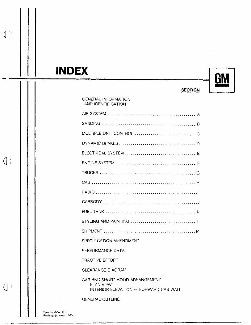
GENERAL INFORMATION AND IDENTIFICATION
AIR SYSTEM ..••.•.....•....••..•....••.....•.......••. A
SANDING .•...•••.....••••...••••..••....••.••.. 0 o. 0.0 B0
MULTIPLE UNIT CONTROL •.•.. 0 C•••• 0 •••• 0 •••• 0 •• 0 • 0 0 •• 0
DYNAMIC BRAKES 0 D0 0 0 0 0 • 0 0 0 • 0 00 ••• 0 •••••• 0 0 0 0 • 0 0 • 0 •••••
ELECTRICAL SYSTEM •.. 0 E0 • 0 •• 0 •• 0 0 0 ••• 0 ••• 0 ••• 0 0 0 ••••• 0
ENGINE SYSTEM .0 0 0 •• 0 •••••••••••• 0 0 •• o. F0 •••• 0 •••••• 0 0
TRUCKS .•. 0 0 •• 0.0 •• 0 ••••• 0 0" 0 •••••• 0 •• 0 ••••••• 0 •••••• G
CAB ..••• 00 H•• 0.0 ••• 0 ••• 0 ••••••••• 0 •••• 0 00 •••••••• 00 ••••
RADIO .. 00 I••• 0 •• 0 ••• 0 •••• 0.0. 0 •• 00 ••••••••••••••••••••• 0
CARBODY 00.0 ••• 0.0 •• 0. 0.' 00, 00.0.0. 0 0 o. 0.0.000 o. 0 00.0 oJ
FUEL TANK K0 •• 0 •• 000 •• 000.0 •• 0 0 0 0 0 ••••• 0 ••• 0.00000 •• 0 0 0
STYLING AND PAINTING ..•..•. 0 L0 ••• 0 ••••• 0 •••••••••••••
SHiPMENT .................•..•....•.. •••• 0 •••••• 00 ••• M0
SPECIFICATION AMENDMENT
PERFORMANCE DATA
TRACTIVE EFFORT
CLEARANCE DIAGRAM
CAB AND SHORT HOOD ARRANGEMENT
(J PLAN VIEW INTERIOR ELEVATION FORWARD CAB WALL
GENERAL OUTLINE
Specification 8091 Revised January, 1980
-, ,..------------------------------------------

GENERAL INFORMATION AND IDENTIFICATION _~i____________________________________________________________________________~
MODEL
TYPE
ARRANGEMENT
NOMINAL DIMENSIONS
DRIVE
WEIGHTS AND
SUPPLIES
CLEARANCES
SAFETY APPLIANCES
CURVE NEGOTIATION
Specification 8091 Revised January, 1980
GM GP40-2 3000 HP Diesel-Electric General Purpose Locomotive.
AAR Designation (B-B), Common designation (0440).
The general arrangement of the locomotive is shown on Elevation and Floor Plan Drawing attached.
The locomotive consists of one unit complete with engine, generator, trucks and all necessary accessories for single unit operation, with a control cab between the long and short hoods.
Distance, pulling face of coupler to centerline of truck ................. 12' 7" Distance between bolster centers. " ......•.......................... 34' 0" Truck rigid wheel base. . . . . . . . . . . . . . . . . • . • . . . . . . . . . . . . . . . . • . . . . . .. 9' 0" Distance, pulling face front coupler to rear coupler .................... 59' 2/1 Width over cab sheeting ........................................ 10' 0-1 /8" Width over handrail supports .................................... 10' 3-1/8" Height, top of rail to top of COOling fan .•.....•.................... 15' 4-3/8/1 Width over basic arm rests ...................................... 10' 4-1/4"
Driving Motors ............•..........................................Four Driving Wheels ........•....••.................•..........•........ 4 Pair Diameter Wheels .........•......•................•....•.......•......40"
Total loaded weight on rails (approximately) ...............•..... 257,000 Ibs. Fuel ........................................................... 2600 gal. Sand ...........•.........................................•..... 56 cu. ft. Cooling water ......................•..........•.•............... 275 gal. Lubricating oil ...•............................................•.. 243 gal.
Locomotive outline drawing found in rear of specification book illustrates clearance conditions.
All steps, grab handles and other safety appliances cover EMD interpretation of FRA requirements.
Truck limits single unit curve negotiation to a 42° or 140 ft. radius curve.
Single unit coupled to a 50 ft. car is limited by car coupler to a 19° or 302 ft. radius curve.
Two units coupled in multiple limited by coupler to a 30° or 190 ft. radius curve.

SECTION A
AIR SYSTEM -.~,------~----.............................................----.....----------------------------------------~ GM
Basic
AIR BRAKES 26L brake schedule including self-lapping independent and standard 26F control valve portions.
BRAKE Wrought steel pipe with AAR fittings are used. Generally, all piping 1/2" 0.0. and PIPING under uses nominal size steel tubing with SAE fittings.
CONDUCTOR'S BRAKE VALVE Recessed conductor's brake valve is provided on the left side of the cab.
AIR One two stage, three cylinder, water cooled direct coupled compressor, having a COMPRESSOR displacement of 254 cu. ft. per minute at 900 RPM. Compressor is equipped with
large oil capacity and disposable intake air filter.
Electric air compressor governor adjusted to maintain reservoir pressure between 130 and 140 psi.
GAUGES AND Large 4-1/2" air gauges fitted with gauge test fittings are standard. Test fitting is TEST FITTINGS also supplied at compressor unloader switch.
MAIN Two 15" diameter x 152" steel reservoirs mounted beneath the underframe. Total RESERVOIR capacity: 49,000 cu. in. No.1 main reservoir equipped with an air operated automatic
drain valve. Centrifugal air filters are provided after both main reservoirs.
WARNING Three chime diaphragm type air horn, two bells pointing forward and one to the rear DEVICES with lever operated modulating horn valve. Horn is located on center line of cab roof.
One 12" locomotive bell with internal pneumatic ringer, located in underframe.
Optional • Engineer alertness systems.
• Overspeed limit. • Compatible operation with locomotives equipped with 6Bl brake schedule.
• Six-cylinder air compressor. • Full flow lube oil filtration system with gear type oil pump on air compressor.
• Air compressor low oil pressure protection.
b • Air flow Indicator. Automatic drain valves on both main reservoirs. • Timed blowndown of main reservoir filters and drain valves. • A-1 charging cutoff pilot valve for break in two protection. • Air compressor ·synchronization. •
Specification 8091 Revised April. 1982
SECTION B
SANDING GM Basic
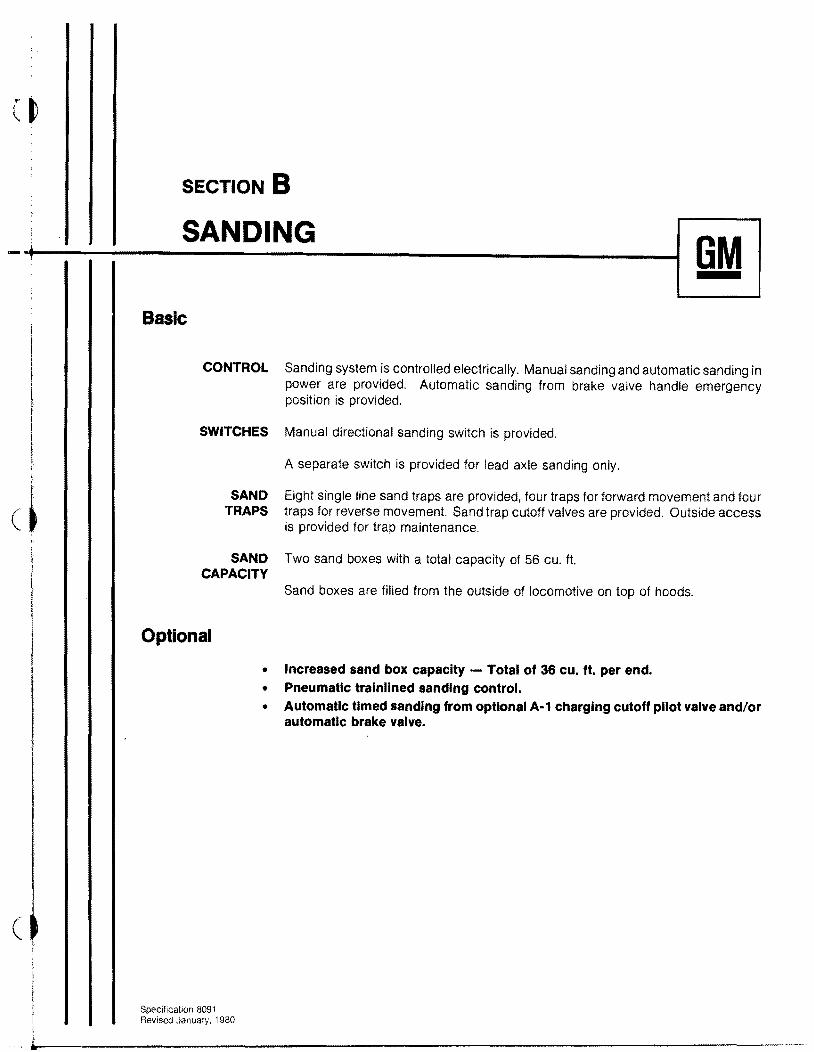
CONTROL Sanding system is controlled electrically. Manual sanding and automatic sanding in power are provided. Automatic sanding from brake valve handle emergency position is provided.
SWITCHES Manual directional sanding switch is provided.
A separate switch is provided for lead axle sanding only.
SAND Eight single line sand traps are provided, four traps for forward movement and tour TRAPS traps for reverse movement. Sand trap cutoff valves are provided. Outside access ( is provided for trap maintenance.
SAND Two sand boxes with a total capacity of 56 cu. ft. CAPACITY
Sand boxes are filled from the outside of locomotive on top of hoods.
Optional
• Increased sand box capacity - Total of 36 cu. ft. per end. • Pneumatic tralnllned sanding control. • Automatic timed sanding from optional A-1 charging cutoff pilot valve and/or
automatic brake valve.
(
Specification 8091 Revised January, 1980
L
(
SECTION C
MULTIPLE UNIT CONTROL OPTIONAL
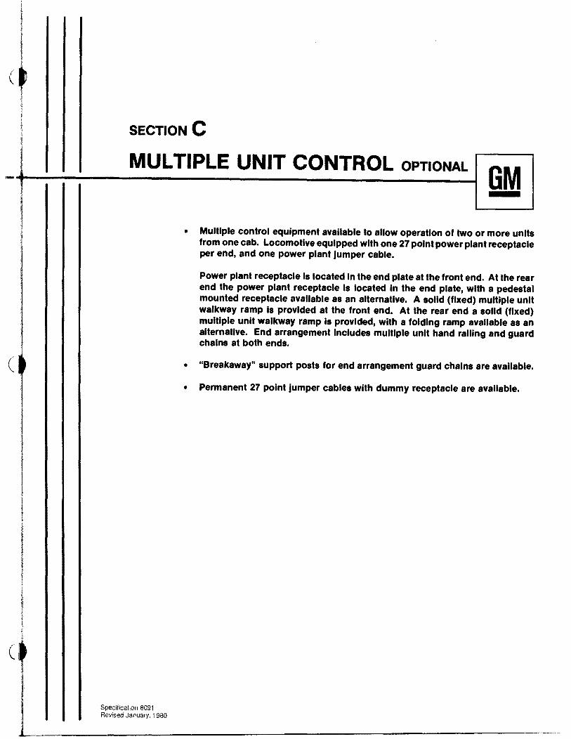
GM • Multiple control equipment available to allow operation of two or more units
from one cab. Locomotive equipped with one 27 point power plant receptacle per end, and one power plant jumper cable.
Power plant receptacle Is located in the end plate at the front end. At the rear end the power plant receptacle Is located in the end plate, with a pedestal mounted receptacle available as an alternative. A solid (fixed) multiple unit walkway ramp Is provided at the front end. At the rear end a solid (fixed) multiple unit walkway ramp Is provided, with a folding ramp available as an alternative. End arrangement Includes multiple unit hand railing and guard chains at both ends.
• "Breakaway" support posts for end arrangement guard chains are available.
I • Permanent 27 point Jumper cables with dummy receptacle are available.
I
c
Specification 8091 REivised January, 1980
L--__________________-------,,

1
f
(~ !
\
' k'-"1---:-----------1I j !
J ~
IlI
\.. f
1
I 1 I
I I i
(),j
SECTION D
DYNAMIC BRAKES OPTIONAL
GM
• Variable dynamic brakes use the traction motors as generators, with the power being dissipated through force ventilated grid resistors mounted In hood above engine. Variable voltage type control Is standard with dynamic brakes. Parallel grid connection to Improve wheel slide protection Is provided. Enforced time delay from power to dynamic brake is standard.
Positive Indication of "power" or "dynamic brake" mode of operation Is clearly shown at controller. 4-1/2" zero-center ammeter contains both "brake" and "power" indication, reading in opposite directions from center for each function.
• A grid current tralnline control feature is available, If desired.
• Extended range dynamic braking providing high brake effort at low speed Is available.
• A self load test feature permitting locomotive loading on Its own dynamic brake grids Is available.
• Grid blower protection Is available preventing dynamic brake operation as result of stalled blower motor or no motor current.
• Dynamic brake ground relay protection.
• Two speed dynamic brakes.
Specification 6091 Revised January, 1980
.iI,......------------------------------------------....
i
I
(
SECTION E
-+-t___E_L_EC_T_R_IC_A_L_S_Y_ST_E_M___-----I[ 8M [
il
(~ j
I 1,
(
Basic
MAIN GENERATOR
GENERATOR EXCITATION
ALTERNATOR
LOCOMOTIVE CONTROL
LOAD CONTROL
ELECTRICAL CONTROL
CABINET
TRAC"nON MOTORS
Specification 8091 Revised January, 1980
EMD AC main generator, with rectified output for delivery to traction motors; 600 volt (nominal) direct current rating, ventilated by blower. Armature shaft supported by single bearing with direct connection to engine crankshaft through alternator rotor and flexible coupling. Adequate capacity to continuously transmit the rated output of the engine under all conditions for which the locomotive is designed,
Excitation for main generator supplied from the alternator through silicon controlled rectifiers,
EMD 200 volt, 3 phase, 16 pole alternator, built integral with main generator, to supply AC power for engine cooling fan induction motors, main generator excitation and inertial separator exhaust fan,
Permanent parallel connection with no field shunting or fully automatic transition with no field shunting, dependent upon selection of gear ratio. High voltage circuits safeguarded by ground protective relay. Full range wheel slip control with automatic sanding under wheel slip conditions.
Load control provided to automatically maintain horsepower output in accordance with the published tractive effort characteristics of the locomotive.
A totally enclosed, readily accessible cabinet houses the locomotive high and low voltage control equipment. Fault annunciator module is provided within the cabinet to indicate equipment malfunction. Cabinet is ventilated from the blower air supply through four element filter using standard pleated paper lube oil filters.
Control equipment includes a full complement of control circuit plug-in modules, high capacity power contactors and gang operated reverser and transfer switches.
An additional cabinet, mounted in the engine room, houses the control equipment for the radiator cooling fan motors. Fuse panel is provided for cooling fan protection.
Four EMD direct current, series wound, forced ventilated, axle hung motors with roller type armature bearings.

SECTION E
ELECTRICAL SYSTEM OM Basic
STORAGE BATTERY
BATTERY BOX
AUXILIARY GENERATOR
32 cell, 64 volt, 420 ampere hour capacity (8 hour rating) battery,
Two battery boxes are provided, one on each side of the short hood. Trap doors in catwalk provided for servicing and bolted removable panels provided for removing batteries. Ventilation and drainage provided. Battery boxes are sized to fit either 17 or 25 plate batteries.
Direct current 10 KW auxiliary generator, driven from engine gear train, provides current for control circuits, lighting and battery charging. Voltage automatically
, j
i ~
ct !
Optional
controlled by static voltage regulator.
• Automatic ground relay reset.
• Lockout of individual traction motors.
• 18 KW AC auxiliary generator.
• Manual power reduction (hump control).
• Push-to-test lights on engine control panel.
Specification 8091 Revised January, 1980
SECTION F
_~__E_N_G_IN_E_S_Y_S_T_EM_____----II OM I
Basic
ENGINE
CARBODY FILTERS
ENGINE AIR INTAKE FILTERS
ENGINE FUEL SYSTEM
ENGINE LUBRICATION
Specification 6091 Revised Apnl. 1962
General Motors sixteen cylinder, 2 cycle diesel engine.
Power assemblies arranged in a 45 degree V, with 9-1 /16" bore and 10" stroke, are secured with one piece crab plates and high strength necked down crab bolts. Improved 1/2" dia. plunger unit fuel injectors, crowned rocking arm rollers and spall resistant cam shafts are provided. Cylinder liners have laser hardened port and upper bore areas. Cylinder heads are water cooled with thin decks. Pistons are oil cooled. Connecting rods are drop forged. Piston is of the floating design. Piston pins are of the rocking pin design. Gear type damper operates on engine oil. Isochronous governor speed control, low engine Idle speed, separate overspeed trip and high crankcase pressure protection are included.
An inertial separator, roof mounted in a separate compartment behind the cab, supplies filtered intake air to major components. The separated contaminants are blown out by an AC fan incorporated in the separator. Filtered air is supplied to the combination traction motor and main generator blower and the engine air filters. Traction motor air is delivered to a duct and plenum chamber system on the underframe and supplies the traction motors with COOling air. The main supply air duct forms the left side walkway. Generator discharge air is used to pressurize the engine compartment.
Disposable paper or fiberglass filter elements provided for engine intake air.
Return flow, single DC motor driven gear pump, protected by suction strainer, and discharge filters with filter by-pass and indicator to insure clean fuel for the engine. Sight glasses permit visual inspection of fuel flow, and relief valve offers protection against excessive pressures.
The engine lubricating oil system is a pressure system using two positive displacement gear type pumps combined in a single unit. One pump delivers oil for the pressure lubricating system, the other for piston cooling. The oil supply to these pumps is drawn from the oil strainer chamber through a common suction pipe.
A scavenging oil pump is used to draw oil from the engine oil pan through a strainer, pump it through the top fill full flow lube oil filter to the cooler core section of the cooler tank and return it to the strainer chamber. Low oil pressure and high oil temperature protection are provided resulting in engine shutdown.
SECTION F
ENGINE SYSTEM GM Basic
TURBOCHARGER An engine driven positive displacement gear type pump supplies oil to the turboLUBRICATION charger through secondary filtration. A separate electrically driven cool down pump
supplies oil to lubricate the turbine for a definite time period before starting and after stopping engine.
ENGINE Pressurized cooling system consisting of two direct driven centrifugal water pumps COOLING on the engine, radiators, and AC motor driven "Q" type unlatched cooling fans for
reduced cooling system noise emission. Fans are located above radiators at rear of long hood. Water cooled oil cooler and water tank mounted as a unit directly in rear of the governor end of engine, automatic water temperature control, hot engine alarm, and engine shutdown in the event of low water level, are included. Improved water fill system to prevent inadvertent opening of the pressure cap is provided. Water level inspection window, in hood, is provided.
ENGINE Four series connected manifolds discharge into turbine of turbocharger which has EXHAUST single exhaust to silencer mounted directly on turbocharger.
ENGINE Engine is started using two 32 volt series connected motors, energized by the STARTING locomotive storage battery. Engine start switch at governor end of engine.
Optional
• Increased capacity oil pan.
• Engine turning jack.
• EMD large or small fuel oil preheater.
• Bolted on engine stubshaft.
• Immersion heater.
• Engine purge control system.
• Turbocharger screen inspection port.
• Starter motor thermal overload protection.
• Mechanical bonded radiators.
• Inertial blower motor failure protection.
• 200 RPM full time low idle - includes special 18KW AC auxiliary generator, gear type oil pump air compressor with drilled rods, and compressor speed up switch.
Specification 8091 Hevised April. 1 982
(J;
SECTION G
____T_R_U_C_K_S---------I[ OM [ Basic
TRUCK Two four-wheel truck assemblies are provided per locomotive and are interASSEMBLIES changeable.
Fully flexible bolster supported on springs providing vertical movement; swing hangers provide lateral movement. The truck frame is supported on each of the four journal boxes by twin coil springs.
Each of the four motors is supported by the driving axle to which it is geared. and a special suspension on the truck transom provides a flexible support. dampening the torque shocks of the motor.
TRUCK Clasp brake rigging provided on each wheel. operated by individual brake BRAKES cylinders. 9" x 8" cylinders, 5.65:1 lever ratio, 14° cast iron brake shoes.
PEDESTALS Lined with "Nylatron" pedestal liners bolted to frame.
PEDESTAL TIE BARS Fitted and applied at the lower end of the pedestal legs, held in position by bolts.
TRUCK CENTER BEARING
RECEPTACLE Truck center bearing receptacle provided with wear plates and dust guard.
SIDE BEARINGS Friction type side bearings.
INTERLOCKS Body and truck interlocks provided each side of the center plate, serving as antisluing device in case of derailment.
BRAKE PINS All pins and bushings hardened and ground.
HAND BRAKE Hand brake provided for the locomotive connected to one brake cylinder lever only. All trucks provided with lever for hand brake connection, making trucks interchangeable.
WHEELS Rolled or cast steel, heat treated, rim quenched, 40/1 diameter with 2-1/2/1 rim. Wheel treads are finished smooth and concentric. AAR diameter index groove is provided to indicate wheel wear.
Specification 8091 Revised January, 1980
SECTION G
IJ ____T_RU_C_K_S_______---t[ GM [
Basic AXLES Axles with journals to suit Hyatt roller bearings. Axle material conforms to physical
properties of current AAR specifications.
JOURNAL Locomotives equipped with Hyatt roiler bearings 6-1/2/1 journals of special EMD BOXES design. Improved rear cover seal and oil fill cup for improved oil retention and
inspection provided. Crowned rollers extend bearing life. Lateral thrust is taken through a cushioning arrangement directly by the box with improved oil flow over thrust block characteristics, Journal box pedestal guides provided with spring steel wear plates.
SLACK ADJUSTERS Pin type slack adjusters,
Optional
• Single shoe brake arrangement.
• Huck fasteners.
• Provision for wheel truing.
• Quick access latch-type traction motor inspection covers.
• High strength alloy steel journal springs.
• Axles splined at both ends.
Specification 8091 f'evised April, 1982

CI
CI
SECTION H
CAB GM
Basic
CONSTRUCTION
CAB SEATS
SPEED RECORDER
CAB HEATING AND
VENTILATING
INSULATION
FLOORING
DOORS
DOOR LOCKS
WINDOWS
WINDOW WIPERS
(J
Specification 8091 Revised January, 1980
Cab is of fabricated steel construction. AAR/EMD Phase /I Clean Cab features are provided throughout the interior of the cab.
The two wall mounted upholstered cab seats have forward and backward as well as height adjustments. Both seats can be turned 180 degrees. Arm rests are provided outside the side windows.
A combination instrument containing the speed indicating dial, speed recorder, tape, and mileage odometer is provided on the front cab wall.
Two combination hot water cab heaters and defrosters with fan driven air circulating system, and selective outside air intake. Each heater is provided with three speed switch for control of fan speed.
Ceiling is lined with perforated metal for sound reduction; backed up by insulation. Acoustic and thermal type insulation is added to the cab side walls and the rear partition of the electrical cabinet.
The cab floor is comprised of plywood covered with linoleum and is elevated above the top of the underframe. A trap door in cab floor and side drop doors provide access to equipment beneath cab floor.
Doors are located at diagonally opposite corners leading to platform alongside hoods and are of honeycomb construction. Doors include interior closure handles and rubber hinge guards. Head bump pads are provided over doors.
The cab doors are fitted with an inside latch and provided with a lock.
Divided center window is provided over low short hood. Side windows on both sides of cab are sliding double sash type and fitted with rounded latches. End windows in doors and cab are stationary and set in a speCial rubber retainer. All window glazing meets FRA requirements.
Total of six air operated window wipers are provided for front and rear windows on both sides of cab and center windshields. Cover is provided over wiper motors and handles are padded. Valves are recessed.
___ (i)
SECTION H
CA_B---------II GM I Basic
ENGINEER'S CONTROL
STATION
ENGINEER'S CONTROL SWITCHES
ENGINEER'S INSTRUMENT
PANEL
MISCELLANEOUS
Optional
Control station, located conveniently to the left of the engineer's seat, includes the engine speed throttle, locomotive reverse lever, automatic and independent brake valve. The lever arrangement is such that the throttle must be in idle before the reverse lever can be removed to isolate the controller. The horn valve, bell valve and independent sander switch are also located in the control stand. Horn valve handle is covered with rubber. Recess in control stand for radio.
Control and lighting switches located within reach of the engineer, including switches for control and fuel pump, generator field, engine run, gauge lights, headlight "bright" front and rear, headlight "dim" front and rear. Engine stop, number and class light and isolation switches located on rear cab wall. Cab heater switches are located on cab heaters, providing individual control.
A lighted instrument panel is provided on top of the engineer's controller containing 4-1/2" air brake gauges, wheel Slip light, PCS "open" light. sand light and the traction motor load indicating ammeter.
Two coat hooks provided in cab.
Two adjustable padded sun visors on engineer's side of cab.
• Third cab seat.
• Water cooler and/or refrigerator.
• Full electric cab heat system (requires 18 KW auxiliary generator).
• Air conditioning system (requires 18 KW auxiliary generator).
• Benelex flooring.
• Awnings/wind deflectors.
• Fixed corner windows_
Specification 8091 Revised January, 1980
------------,------------------------------------------------------

SECTION I
_____R_A_D_I_O_O_P_TIO_N_AL_______---tl GM I
• The choice of radio equipment will depend upon customer requirement. Radio applications vary from minimum provision to complete application.
Basic engineer's control stand includes recess for radio.
Specilicalion 8091 Revised January, 1980

SECTION J
CARBODY GM
Basic
FRAMING Underframe is of constant section design and serves as main carrying member for hoods, cab and equipment. Two side sills supported by center sills support catwalk alongside of hoods. Draft gear pockets are welded to the built -up platform construction between center sills. The structure is all welded construction.
COLLISION POSTS Collision posts are designed integrally with low front hood and welded to underframe.
FLOORING Floor plates with antis kid surface are welded to underframe on end platforms and alongside of hoods.
LlNDERFRAME CENTER
BEARINGS Welded to body bolster assembly.
SHORT HOOD Short hood with separate toilet compartment with access door, floor drain and outside air ventilator. Continuous weld around floor plates and alcove for water cooler. Entrance from cab to short hood is a stair arrangement with full height opening. A hatch door is provided on top of the short hood to facilitate toilet or water cooler removal.
LONG HOOD The power plant compartment is designed to a minimum width to provide a walkway around the hood. Doors are provided which give access to power plant equipment and allow removal of complete power assemblies. Hatches supporting cooling fans can be removed separately for removal of radiators. The hood is bolted to the inertial filter compartment and to the deck and can be removed complete with radiators and cooling fans for major repairs. When provided, dynamic brake hatch can be removed separately.
HOOD DOORS All side doors have outside hinges and latches.
LIFTING EYES Provision is made for lifting eyes on hood and hatches to facilitate handling with a crane.
MARKER AND Four standard combination flag and light brackets are provided. Two each are FLAG BRACKETS located at front and rear of locomotive.
SIDE STEPS Side switchman's and platform mounting steps, meeting Federal Railroad Administration requirements for locomotives used in switching service, are provided at each corner of locomotive.
Specification 8091 Revised April, 1982
SECTION J
(I_!___C_A_R_B_O_D_y______--t1 GM I Basic
UNCOUPLING DEVICE
COUPLERS
DRAFT GEAR
HEADLIGHT
CLASSIFICATION LIGHTS
NUMBER BOXES
LOCOMOTIVE LIGHTING
FIRE EXTINGUISHERS
JACKING PADS
BALLAST
Specification 8091 Revised January. 1980
Each end of the locomotive is provided with a top operating device arranged to operate from either side of the locomotive.
Type "E", 6-1/4" x 8" shank, 28-1/2" long. Maximum operational swing of coupler is 1JO to either side of centerline. Maximum free (manual) swing is 4° from center.
National Castings NC-391 rubber draft gear with alignment control.
Twin sealed-beam headlights, front and rear, are equipped with two 200 watt, 30 volt sealed-beam units. Bright and dimmer switch for each light provided in operator's cab.
Classification lights built into each corner of front and rear hood.
Four lighted number boxes, two on each end of locomotive, mounted at an angle for both forward and side visibility. Number boxes at cab end are provided with outside access doors.
Lights and outlets are as follows:
1. Two recessed ceiling cab lights with individual switches. 2. Two engine room lights. 3. Eight number lights. 4. Three gauge lights. 5. Outlet receptacles: one in engine room, one in cab. 6. Two short hood compartment lights. 7. Four classification lights. 8. Two platform lights, one each end. 9. Four stepwell lights.
Two 20 lb. Ansul, one located in cab, the other in the engine compartment.
Combination jacking pad and cable sling is provided near each bolster at side sill.
The locomotive is basically designed for balance.
CI
SECTION J
~':")--'!J....!.._C_A_R_B_O_DY_______II aM I Optional
(J
Specification 8091
• Reinforced nose.
• Anti-climber.
• Snow plows.
• NC390 Draft gear.
• Type F coupler.
• Signal light/roof top beacon.
• Toilet.
• Lifting eyes in the end sheets.
• Ground lights.
___~~_~~R~e~Vis~e~d=Ja~nu=a~ry~,1~98~O___________________________________.~.._ ...

SECTION K
____FU_E_L_T_A_N_K______-----II GM I
Basic
2600 gallon capacity, fuel tank built of heavy gauge steel, with baffle plates, located underneath the locomotive body. One filling station on each side. Tank equipped with venting, cleanout plug, and nonremovable water drain.
One dial type fuel gauge on right side of tank and one direct reading type fill Sight glass on each side of tank. Each filling station provided with electric emergency fuel cutoff actuating button. Similar pushbutton located in cab. When operated, engine stops immediately.
Optional
• 3600 gallon fuel tank with Intermediate sizes also available.
• Automatic fill adapters.
• 100 gallon retention tank (decreases total fuel capacity by 100 gallons).
Specification 8091 Revised January, 1980
SECTION L
_~__S_T_Y_LI_N_G_A_N_D_P_A_IN_T_IN_G___~[ 8M [
Basic
OUTSIDE Acrylic lacquer except for the fuel tank, air reservoirs, trucks and other underFINISH carriage surfaces which are enamel.
Generally, a Basic styling and painting scheme is a two color or simple three color scheme. Handholds and long hood handrails should be the same color as the primary long hood color. Color lines should not run through door locks, hinges, shutters or other difficult to mask areas. Multicolor or exotic design logos or medallions should be optional premasked reflective or non-reflective material rather than painted. EMD should be given license to adjust paint design locations for manufacturing practicability, visual aesthetics and efficiency.
LONG HOOD AND Inside of long hood, short hood and components contained therein painted suede
SHORT HOOD gray enamel. All air, fuel, water and lube oil piping are color coded at points of connection.
CAB Inside painted suede gray enamel.
UNDERCARRIAGE Black enamel unless otherwise specified.
TRUCKS AND TANKS Black enamel unless otherwise specified.
Optional
• Permanent front end identification plates.
• Polyurethane paint.
• Reflective/Non-reflective markings.
C)
Specification 8091 Revised January, 1980
CI
SECTION M
SHIPMENT OM Basic
CONSIGNMENT AND ROUTING In accordance with written instructions furnished by the customer.
OPERATING SUPPLIES Locomotive is drained of fuel oil, lube oil and water prior to shipment.
Specification 8091 Revised January, 1980

____S_P_E_C_IF_IC_A_T_IO_N_A_M_E_N_D_M_E_N_T_--I[ GM [
Electro-Motive Division Locomotive Specification No. 8091 is amended to incorporate certain remanufactured components when a "Replacement" locomotive is purchased.
The items listed below corstitute the maximum n~mber of remanufactured components that may be incorporated in the GP40-2 replacement locomotivfl
ENGINE PARTS " Crankshaft
Crankshaft gear No. 1 idler gear
.. Camshaft drive gears Camshaft bearing blocks Lube oil scavenging pump
/ Governor drive gear , Accessory drive gear (. Accessory drive housing
$)<h'aust valve bridge/' vlnjector crab
AUXILIARY GEf\IERATOR
D14 ALTERNATOR
TRACTION MOTOR PARTS / 'j ":;'1 ; j •
Frame assembly and pole pieces / ,I Ji""
Armature core, commutator, and armature shaft Bearing housing and assembly parts Axle caps
.' ,
TRUCK ASSEMBLY PARTS ,.. Axles and axle gears .\ I
Frame, bolster, spring plank, safety straps, pedestal tie bars, and side bearing clips
Coil and elliptic springs and coil spring seats Brake cylinders Brake levers and straps Brake heads Roller bearing journal box assemblies i::~.) iv \
Electro-Motive Division General Motors Corporation Specification Amendment 8091-3 La Grange. Illinois Revised April 1, 1982
--------------------~--.-.-

PERFORMANCE DATA GM
OPTIONAL GEAR
RATIOS The choice of gear combinations will depend upon the service contemplated.
GEAR RATIO 62:15 61 :16 60:17
MAX. SPEED 70 76 82
MINIMUM SPEED HORSEPOWER
22.9 24.8 26.9
MINIMUM CONTINUOUS SPEED (MPH)
11.3 11.3 11.2
HORSEPOWER The GP40-2 locomotive develops 2000 nominal horsepower into the generator for RATING traction at gOO RPM of the engine under the following conditions:
60° F air intake temperature 29.9 inches hg barometer (minimum) 0.845 specific gravity fuel .83 engine governor rack setting 60° F fuel temperature
Specification 8091 Revised April, 1982
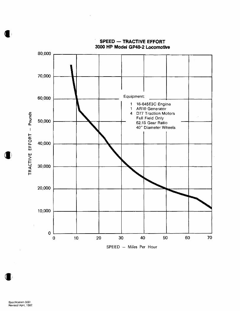
SPEED - TRACTIVE EFFORT 3000 HP ModeJ GP4D-2 Locomotive
80,000
70,000
60,000
III -c c: 0 ::J 50,000
Q.
I-a: 0 LL 40,000 LL W
wtI > IU 30,000<a: I
20,000
10,000
o o 10 20 30 40 50 60 70
SPEED - Miles Per Hour
1
~ Equipment:
1 16-645E3C Engine 1 AR10 Generator 4 077 Traction Motors
Full Field Only
" 62:15 Gear Ratio 40" Diameter Wheels
~ '\ ~
" ~ ~
"
Specificahon 8091 Revised April. 1982
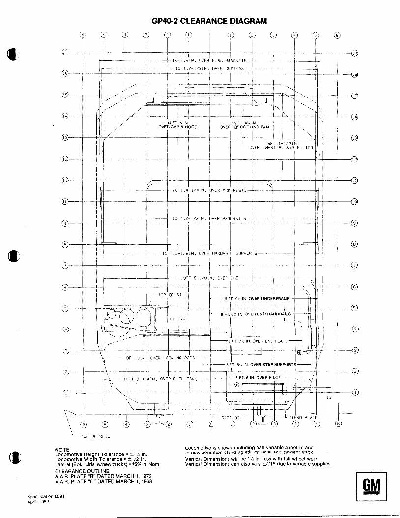
GP40-2 CLEARANCE DIAGRAM
(I)
~.~6~1~1~_~~2)~~:-41~_~..~t~~_G~V~i~1 I I
r-'--.....~-+----+---+- IOICT .51 'J. OVER FLf\G BRACKE TS -1------
i · IOFT.21/81N.OVERGUTTERS~- ~- Ji @---'~+----'-f-I-------+-~--~-~'---~--i---- ... f--~-- ··-·-·~--t········--j---........,---I---H+--L.---116
I i
-~ --I-- i-----i----+~~-------l
15FT .1~1/4IN. INERT:AL AIR FILTER
i f'
I I I
v-~ 1--'1 I-~ ~---If~----+-- iOFT.4··1I4IN. OVER ARM RESTS-L~•.. -, ....I---- .~--
: Io)---~+~~,~--H+-- --: --+,.-. -~-.J..---+-----+---+---+--------Il------f..-
1- +-------+'-~-_~_t_-~.-.-21--"m.l", ''""P~''''-+--;!..-.~~...~~=!_~~~ ::~-'--~~...'--+f-+--+---{ 1
: 1
I 1
1
I
I 1
....._,
I I
OVER Il
!i I
iOJT .O-1/81 I N. eVER I
. \\ -®I--~I·····-·,If-···-,-----+-·~-\-k--\--I--I-----+- ....... 6
I
SLL -' FIT. O\; IN, OVER UNOERFRAME
, '-IL
NOTE: Locomotive Height Tolerance ±1'h In,
Locomotive is shown including half variable supplies and in new condition standing still on level and tangent track,
Locomotive Width Tolerance ±1/2 In, Vertical Dimensions will be 1 Vz In, less with full wheel wear, Lateral (Bol. +Jrls. w/new trucks) ~ ±2% In. Nom. Vertical Dimensions can also vary ±7/16 due to variable supplies.
CLEARANCE OUTLINE: A.A.R. PLATE "8" DATED MARCH 1, 1972 AAR. PLATE "C" DATED MARCH 1,1968
Specification 8091 April,1982
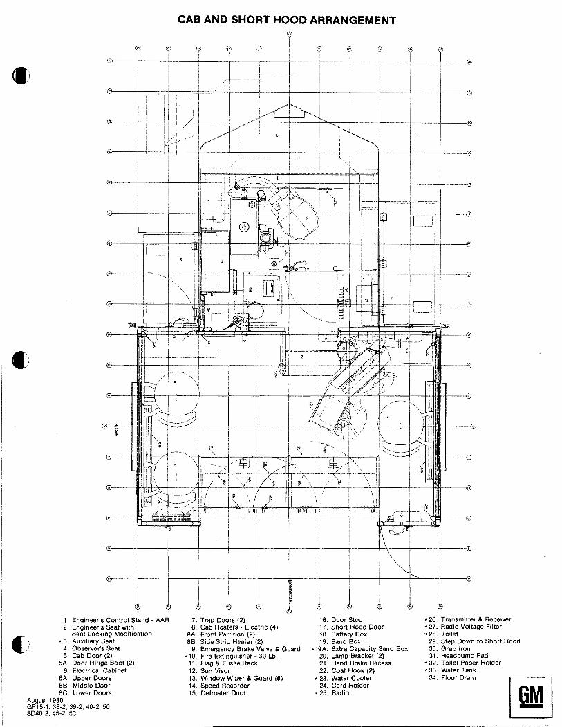
CAB AND SHORT HOOD ARRANGEMENT
1. Engineer's Control Stand AAR 2. Engineer's Seat with
Seat Locking Modification '3. Auxiliary Seat
4. Observer's Seat 5. Cab Door (2)
5A. Door Hinge Boot (2) 6. Electrical Cabinet
6A. Upper Doors 6B. Middle Door 6C. Lower Doors
August 19S0 GP15-1, 3S-2, 39-2, 40-2, 50 SD40-2, 45-2, 50
7. Trap Doors (2) S. Cab Heaters - Electric (4)
SA. Front Partition (2) SB. Side Strip Heater (2)
9. Emergency Brake Valve & Guard * 10. Fire Extinguisher 30 Lb.
11. Flag & Fusee Rack 12. Sun Visor 13. Window Wiper & Guard (6) 14. Speed Recorder 15. Defroster Duct
16. Door Stop 17. Short Hood Door 1S. Battery Box 19. Sand Box
*19A. Extra Capacity Sand Box 20. Lamp Bracket (2) 21. Hand Brake Recess 22. Coat Hook (2)
* 23. Water Cooler 24. Card Holder
* 25. Radio
* 26. Transmitter & Receiver * 27. Radio Voltage Filter • 2S. Toilet
29. Step Down to Short Hood 30. Grab Iron 31. Headbump Pad
* 32. Toilet Paper Holder • 33. Water Tank
34. Floor Drain

CAB ARRANGEMENT - FORWARD CAB WALL
16. Door Stop * 26. Transmitter & Receiver 1. Engineer's Control Stand - AAR 7. Trap Doors (2) 2. Eng! neer's Seat with 8. Cab Heaters - Electric (4) 17. Short Hood Door .27. Radio Voltage Filter
Seat Locking Modification 8A. Front Partition (2) 18. Battery Box .28. Toilet * 3. Auxiliary Seat 8B. Side Strip Heater (2) 19. Sand Box 29. Step Down to Short Hood
4. Observer's Seat 9. Emergency Brake Valve & Guard *19A. Extra Capacity Sand Box 30. Grab Iron
<J 5. Cab Door (2) *10. Fire Extinguisher - 30 Lb. 20. Lamp Bracket (2) 31. Headbump Pad
5A. Door Hinge Boot (2) 11. Flag & Fusee Rack 21. Hand Brake Recess * 32. Toilet Paper Holder
6. Electrical Cabinet 12. Sun Visor 22. Coat Hook (2) * 33. Water Tank 6A. Upper Doors 13. Window Wiper & Guard (6) * 23. Water COOler 34. Floor Drain
68. Middle Door 14. Speed Recorder 24. Card Holder 6C. Lower Doors 15. Defroster Duct * 25. Radio
August 1980 GP15-1, 38-2, 39-2, 40-2, 50 S040·2, 45-2, 50

MODEL GP40-2 - 3000 HP DIESEL ELECTRIC GENERAL PURPOSE LOCOMOTIVE
() LEGEND 1. ENGINE -16-645E3C 2. GENERATOR/AL TERNATOR AR10A6/D18 3. TRACTION MOTOR - GENERATOR BLOWER 4. AUXILIARY GENERATOR 5. ELECTRICAL CONTROL CABINET. 6. AIR COMPRESSOR (WBO SHOWN) 7. ENGINE EXHAUST SILENCER 8. HANDBRAKE 9. SAND BOX FILLER
10. LUBE OIL COOLER 11. ENGINE WATER TANK 12. 48 IN. COOLING FAN "Q" TYPE 13. RADIATOR 14. HORN 15. EXHAUST MANIFOLD 16. SAND BOX
*17. MU END CONNECTION 18. HEADLIGHT
NOTE: LOCOMOTIVE HEIGHT TOLERANCE"' ±1'h IN. LOCOMOTIVE WIDTH TOLERANCE = ±112 IN. LATERAL (Bol. + Jrls. w/new trucks) = ±2% IN. NOM.
Locomotive is shown including half variable supplies and in new condition standing still on level and tangent track.
19. BATTERIES 20. FUEL TANK (2600 GAL. SHOWN) 21. MAIN AIR RESERVOIRS 22. COOLING AIR INLET & SHUTTERS 23. LUBE OIL FILTER 24. ENGINE AIR FILTER 25. INERTIAL AIR SEPARATOR 26. NUMBER BOX 27. TRACTION MOTOR AIR DUCT 28. BELL
*29. DYNAMIC BRAKE FAN 30. PILOT 31. COUPLER 32. FUEL FILTER 33. TRUCK - 4 WHEEL 34. ELECTRICAL CABINET AIR FILTER 35. ENGINE ROOM VENT
·MODIFICATION
I
~._J'"
Specification 8091 Electro-Motiv, Division IIH&. i
La Grange, Illinois Revised April, 1982
31