LPT 305-E 1011kreovent.ru/media/images/product/otkrte_gradirni_s...P e Condensers v i aporat MC-E,...
24
L OW P ROFILE IN FORCED DRAFT, COUNTERFLOW COOLING TOWERS Thermal Performance from 120 to 1460 kW Nominal Capacity D ELIVERING Q UALITY ... F OCUSED ON P ERFECTION ! Bulletin 305-E Metric CERTI FI ED EN I SO 9001 NEW! NEW! NEW! NEW! Mr. GoodTower ® Mark Owned by the Cooling Technology Institute
Transcript of LPT 305-E 1011kreovent.ru/media/images/product/otkrte_gradirni_s...P e Condensers v i aporat MC-E,...

L O W P R O F I L E I N
F O R C E D D R A F T, C O U N T E R F L O W C O O L I N G T O W E R S
Thermal Performance from 120 to 1460 kW Nominal Capacity
D E L I V E R I N G Q U A L I T Y. . . F O C U S E D O N P E R F E C T I O N !
Bulletin 305-E Metric
C E R T I F I E D E N I S O 9 0 0 1
NEW!NEW!NEW!NEW!
Mr. GoodTower®
Mark Owned by the Cooling Technology Institute

2©2010 EVAPCO Europe
S ince its founding in 1976,EVAPCO, Inc. has become aworld-wide leader in supplying
quality cooling equipment for thou-sands ofcustomers in both the commercial andindustrial markets.
EVAPCO’s success has been the resultof a continual commitment to productimprovement, quality workmanship anda dedication to providing unparalleledservice.
Our emphasis on research anddevelopment has led to many productinnovations – a hallmark of EVAPCOthrough the years.
The ongoing R & D Program enablesEVAPCO to provide the most advancedproducts in the industry – technologyfor the future, available today.
With 17 facilities in eight countries andover 170 sales offices in 42 countriesworld-wide, EVAPCO is ready to assist inall your equipment needs.
The new & improved EVAPCO Model LPTforced draft centrifugal cooling towersnow feature IBC Compliance in addition toCTI Certification.These features reinforce EVAPCO’s positionas the leading manufacturer of forced draftevaporative cooling equipment.
Z-725 Heavy Mill
Galvanized Steel
Construction
(Stainless steel availableas an affordable option)
Double-Brake
Flange Joints
• Stronger than single-brake designs by others
• Increases field riggingjoint integrity
• Greater structuralintegrity
Stainless Steel
Strainer
• Resists corrosionbetter than othermaterials
ZINC
ZINC
STEELZ-725
Z-600
Z-275
EVAPCO
others
E A S Y S O L U T I O N S , B E T T E R C H O I C E S !
CTI CertifiedRefer to page13 for details
†
† Mark owned by the Cooling Technology Institute

3 DESIG
NOPTIO
NS
APPLICATIONS
IBC
CTI
ENGINEERING
SOUND
Totally Enclosed Fan Motors &
Superior Drive System
• Assures long life
• Located in dry, incoming air-stream,allowing normal maintenance to bedone from the outside of the unit
• If required, motor can be easilyremoved
• Solid fan shaft
• Belt tensioning and bearing lubricationcan be performed from outside the unit
• Motor is fully accessible by removingone inlet screen
DESIGN AND CONSTRUCTION FEATURES
PVC Spray Distribution Header
• Nozzles are threaded into the header to ensure proper orien-tation.
• Fixed position nozzles require little maintenance.
• Large orifice nozzle with integral sludge ring toprevent clogging.
• Treaded end-caps on distribution piping for ease of cleaning
IBC CompliantDesignRefer to page 11for details
Certificate of ComplianceLSTB, LPT Cooling Towers
PMWQ, LSW(A/B), LRW(B) Closed Circuit CoolersPMC-E, LSCB and LRC Evaporative Condensers
Are certified to meet or exceed the Seismic and Wind Load Provisions set forth in the applicable building codes for this project.
These products have been manufactured following all applicable quality assurance programs.
Applicable Building Codes:IBC 2006ASCE-7NFPA 5000
Referenced Report:VMA-43387
Approval Agency:VMC Seismic Consulting Group
EVAPCO...Specialists in Heat Transfer Products and Services. FD IBC COC 001
Exclusive EVAPAK® fill
• Provides the most efficient thermalperformance per plan area
• Suitable for use as a working platform
E A S Y S O L U T I O N S , B E T T E R C H O I C E S !
Water Saver Drift Eliminators
• New patenteddesign reduces driftrate to < 0.001%
• Saves water andreduces watertreatment cost
• Greater structuralintegrity vs. oldstyle blade-type
• Recessed intocasing for greaterprotection
• Drift rate certificationsEurovent OM-14-2009
Contractor Features
• Low Rigging Cost
• Low Installation Cost
Owner Features
• Low Profile (low height)
• Low Maintenance
Engineering Features
• CTI Certified Performance
• Lowest Sound with Full
Attenuation
• IBC Compliant Design

4
D E S I G N F E A T U R E S
Reduced Height and ImprovedMaintenance AccessibiltyThe LPT unit has been designed to satisfy installationrequirements where height limits must be observed.The lower profile design of the LPT does not, how-ever, sacrifice maintenance accessibilty for reducedheight. Its unique casing design allows the water dis-tribution system, cold water basin, fan section andother unit compo-nents to be easilymaintained.Small, light weightsections of the drifteliminators can beeasily removed toaccess the water dis-tribution system. Large circular access doors arelocated on both sides of the cold water basin toallow adjustment of the float assembly, removal ofthe stainless steel strainers and cleaning of the basin.The fan motor and drive system are located at oneend of the unit and are completely accessible byremoving the inlet screens. Although, routine main-tenance can be performed from the exterior of theunit without removing the inlet screens.
Cold Water Basin AccessThe LPT cold water basin can be easily maintainedfrom the sides of the cooling tower through large,circular accessdoors. Theunique steppedconfiguration ofthe LPT heattransfer sectionallows unimped-ed access to thebasin to allowadjustment of the float assembly, removal of thestainless steel strainers and basin cleaning.
Mechanical Drive System AccessThe LPT mechanical drive system is easy to main-tain. Bearing lubrication and belt adjustment canbe per-formed fromoutside theunit. Thereis no need toremove fanscreens tomaintainimportant
drive components. In addition, the locking mecha-nism used to maintain belt tension can also workas a wrench to adjust the belt.
Motor LocationAll LPT models have TEFC motors mounted onadjustable motor bases, similar in design to thelarge EVAPCO AT Cooling Tower Drive System.This same technology has been utilized in the LPTdesign to allow belt adjustment to be performedexternally. In addition, the motor is located underthe protective fan system enclosure and can beeasily accessed by removing one air inlet screen.
Fan Access-Split HousingAnother unique feature of the LPT Cooling Towers aresplit fan housings. The split fan housing on the LPTallows quick removal of the fans from the front end ofthe unit. This feature allows fan removal when unitsare placed side by side where space is minimal.
Transport of a Pre-Assembled UnitThe LPT ships fully assembled. This means lowertransport costs and no further expenses at the jobsite for assembly.LPT units are ideal fortruck-mounted appli-cations for remotesites or temporaryinstallations.
Efficient Drift Eliminators*An extremely efficient drift eliminator system is stan-dard on the LPT Cooling Tower. The system removesentrained water droplets from the air stream to limitthe drift rate to less than 0.001% of the recirculatingwater rate. With a low drift rate, the LPT CoolingTower saves valuable water and water treatmentchemicals. The LPT can belocated in areas where mini-mum water carryover is criti-cal, such as parking lots.The drift eliminators areconstructed of an inertpolyvinyl chloride (PVC) plas-tic material which effectivelyeliminates corrosion of these vital components. Theyare assembled in sections to facilitate easy removalfor inspection of the water distribution system.EVAPCO can provide the Eurovent drift rate certifi-cate in accordance with OM-14-2009.
* US Patent No. 6315804B1Belt Adjustment
Bearing Lubrication
H
M
M
DESIG
NE A S Y S O L U T I O N S , B E T T E R C H O I C E S !

5
D E S I G N F E A T U R E S
EVAPCOAT:
Z-725 Hot-Dip Galvanized Steel Construction
The Z-725 Mill Hot-Dip Galvanized SteelConstruction is the heaviest level of galvanizingavailable for manufacturing evaporative coolingtowers and has more zinc protection than com-petitive designs using Z-275 and Z-600 steel.
EVAPCO has been a leader in the industry indeveloping heavier galvanizing, and was thefirst to standardize on Z-725 mill hot-dipgalvanized steel. Z-725 designation means thereis a minimum of 725 g of zinc per m2 of surfacearea present on the steel..
During fabrication, all panel edges are coatedwith a 95% pure zinc-rich compound forextended corrosion resistance.
The EVAPCOAT Corrosion Protection System isthe heaviest galvanized coating available forextended corrosion protection eliminating theneed for costly, unreliable epoxy paint finishes.
Stainless Steel Material Options
The EVAPCOAT Corrosion Protection System issatisfactory for most applications. If additionalcorrosion protection is required the followingstainless steel options are available (AISI 304 and316). Please contact your local EVAPCO represen-tative for pricing.
Consult the factory for construction details.
EVAPAK® Cooling Tower Fill
The patented* EVAPAK® fill design used in theforced draft cooling tower line is the culmina-tion of thousands of hours of research and test-ing conducted by EVAPCO’s research engineers.This program has produced a cooling tower fillwith superior heat transfer, reduced channelingin flow passages, improved drip enhancementfor lower air side pressure drop and exceptionalstructural strength.
The fill is specially designed to induce highly tur-bulent mixing of the air and water for heattransfer. This is made possible by forming theraw fill into corrugated panels on which thereare small ridges. These ridges serve many pur-poses, one of which is to create agitation in boththe water and the air in the tower. This increasein turbulence prevents channeling of the waterand promotes better mixing of air and water,therefore improving heat transfer. In addition,special drainage tips allow high water loadingswithout excessive pressure drop.
The fill is constructed of inert polyvinyl chloride,(PVC). It will not rot or decay and is formulatedto withstand water temperatures of 55°C.Because of the unique way in which the cross-fluted sheets are bonded together, the structuralintegrity of the fill is greatly enhanced, makingthe fill usable as a working platform.
A high temperature fill is available for water temperatures exceeding 55°C.Consult your EVAPCO representative for furtherdetails.
EVAPAK® FILL
*U.S. Patent No. 5,124,087
ZINC
ZINC
STEELZ-725
Z-600
Z-275
EVAPCO
others
DESIG
N
E A S Y S O L U T I O N S , B E T T E R C H O I C E S !

6
O P T I O N A L E Q U I P M E N T
Pan Freeze Protection
Remote SumpWhenever a cooling tower is idle during sub-freezingweather, the water in the sump must be protectedfrom freezing and damaging the pan. The simplestand most reliable method of accomplishing this is witha remote sump tank located in a heated space in thebuilding under the tower. With this system, the waterin the tower drains to the indoor tank whenever thepump is shut-off. When a tower is ordered for remotesump operation, the standard float valve and strainerare omitted, and the unit is provided with an over-sized water outlet connection. When a remote sumpis not possible, a supplementary means of heating thepan water must be provided.
Electric HeatersElectric immersion heaters are available factoryinstalled in the basin of the tower. They are sized tomaintain a +5°C pan water temperature at 18°C ambi-ent with the fans off. They are furnished with a combi-nation thermostat/low water protection device tocycle the heater on when required and to prevent theheater elements from energizing unless they are com-pletely submerged. All components are enclosed inrugged, weather proof enclosures for outdoor use.Heater control packages are available as an option.Contact your local EVAPCO representative for furtherdetails.
Electric Water Level ControlEVAPCO LPT Cooling Towers are available with anoptional electric water level control system in placeof the standard mechanical makeup valve and floatassembly. This package provides accurate control ofthe pan water level and does not require field adjust-ment, even under widely variable operating condi-tions.
The control was designed by EVAPCO and consists ofmultiple heavy duty stainless steel electrodes. Theseelectrodes are mounted external to the unit in a verti-cal stand pipe. For winter operation, the stand pipemust be wrapped with electric heating cable and insu-lated to protect it from freezing.The weather protected slow closing solenoid valve forthe makeup water connection is factory supplied and isready for piping to a water supply with a pressurebetween 140 (minimum) and 350 kPa (maximum).
Vibration IsolatorsThe fans on EVAPCO cooling towers are balanced andrun virtually vibration free. In addition, the rotatingmass is very small in relation to the total mass of thecooling tower, further reducing the possibility ofobjectionable vibration being transmitted to thebuilding structure. As a result, vibration isolation isgenerally not required.In those cases where it is determined that vibrationisolation is necessary, spring type vibration isolatorrails can be furnished. The rails are constructed ofheavy gauge Z-725 hot-dip galvanized steel for superi-or corrosion resistance. Rails are designed to bemounted between the cooling tower and the support-ing steel framework. They are 90% efficient and haveapproximately 25 mm static deflection. Rails aredesigned for wind loading up to 80 km/h.It is important to note that vibration isolation must beinstalled continuously along the full length of the cool-ing tower on both sides of the unit. Point isolatorsmay be used between the supporting steel and thebuilding framework, but not between the unit and thesupporting steel.
IBC Certification cannot be given when vibrationisolators are installed.
Other Options Available:Pony MotorsStainless Steel Material OptionsTapered Discharge HoodsSolid Bottom Panels for Ducted ApplicationsFill Access Doors
BASIN HEATER*See factory certified prints for detailed drawings.
*
Model No. KWLPT 316 to 366 (1) 2LPT 516 to 596 (1) 3LPT 519 to 569 (1) 3LPT 5112 to 5712 (1) (6)LPT 819 to 879 (1) (7)LPT 8112 to 8812 (1) (9)
* Electric heater selection based on -18°C ambient temperature.For alternate low ambient heater selections, consult the factory.
Electric Pan Heaters
OPTIO
NS
E A S Y S O L U T I O N S , B E T T E R C H O I C E S !

7
A P P L I C A T I O N S
LPT Ships Factory AssembledThe compact, unitary design of the LPT CoolingTower allows them to be shipped completelyassembled. This results in lower transportationcosts and no assembly requirements at the job site.Only one lift is required to rig the LPT.Note: Options such as attenuation and dischargehoods will require additional lifts.
Structural Steel SupportThe recommended method of support for the LPTcooling tower is two structural “I” beams locatedunder the outer flanges and running the entirelength of the unit. Mounting holes 19 mm indiameter, are located at the bottom channels ofthe pan section to provide for bolting to the struc-tural steel. Refer to certified drawings from thefactory for bolt hole locations. See the drawingand chart below for unit dimensions.
Note:1) Beams should be level before setting the unit in
place.2) Do not level the unit by shimming between it
and the “I” beams as this will not provide prop-er longitudinal support.
3) Beams should be sized in accordance withaccepted structural practices. Support beamsand anchor bolts are to be furnished by others.
Indoor InstallationAll LPT Cooling Towers can be installed indoorswhere they normally require ductwork to andfrom the unit. The design of the ductwork shouldbe symmetrical to provide even air distributionacross both intake and discharge openings.Guidelines for Ducted Applications:
1) The static pressure loss imposed by the duct-work must not exceed 120 Pa. The fan motorsize must be increased for ESP up to 120 Pa.
2) For ducted installations, the solid bottom paneloption must be ordered. A blank off plate willalso be provided in lieu of the side air inletscreens with this option.
3) Important, Access Doors must be located in theductwork for service to the fan drive compo-nents and water distribution system.
Drawings are available showing recommendedductwork connections. See EVAPCO’s LayoutGuidelines for additional information.
DesignEVAPCO LPT Cooling Towers have heavy-duty con-struction and are designed for long, trouble-freeoperation. However, proper equipment selection,installation and maintenance are necessary toinsure good unit performance. Some of the majorconsiderations in the application of a cooling towerare presented below. For additional information,contact the factory.
Air CirculationIn reviewing the system design and unit location,it is important that enough fresh air is provided toenable proper unit performance. The best loca-tion is on an unobstructed roof top or on groundlevel away from walls and other barriers. Caremust be taken when locating towers in wells orenclosures or next to high walls. The potential forrecirculation of the hot, moist discharge air backinto the fan intake exists. Recirculation raises thewet bulb temperature of the entering air causingthe leaving water temperature to rise abovedesign. For these cases, a discharge hood or duct-work should be provided to raise the overall unitheight even with the adjacent wall, thereby reduc-ing the chance of recirculation. For additionalinformation see the EVAPCO Equipment LayoutManual. Engineering assistance is also availablefrom the factory to identify potential recirculationproblems and recommend solutions.
Dimensions (mm)Model No. A (unit only) A (with atten.) B
LPT 316 to 366 3096 4206 1029LPT 516 to 596 3727 4842 1540LPT 519 to 569 4629 5740 1540LPT 5112 to 5712 5553 6664 1540LPT 819 to 879 4629 5740 2388LPT 8112 to 8812 5553 6664 2388
Note: Ductwork/solid bottom panels negate the CTICertification.
APPLICATIONS
E A S Y S O L U T I O N S , B E T T E R C H O I C E S !

8
Capacity ControlThe design wet bulb for which the cooling tower issized occurs only a small percentage of the time.Unless colder water temperatures are beneficial tothe process being cooled, some form of capacitycontrol will be needed. A common control practice is to cycle the fans offwhen leaving water is below the minimum allow-able temperature. However this does not provideclose control of the leaving water temperatureand may cycle the motor on and off more than therecommended limit of six (6) starts per hour.Another method is to use two-speed fan motorswhich add a second step of control. Two speedfan motors are an excellent method of capacitycontrol for the LPT. This arrangement gives capac-ity steps of 10% (fans off), 60% (fans half-speed)and 100%. A temperature controller can be sup-plied to set control at 3 °C increments, so fairlyclose temperature control can be maintained with-out excessive cycling of the fan motor.Two-speed motors also save operating costs. Athalf-speed the motor draws approximately 15% offull load power. Since maximum wet bulb andmaximum load very seldom coincide on air condi-tioning systems, the cooling tower will actuallyoperate at half speed 80% of the time. Thus,power costs will be reduced by approximately 85%during the major portion of the operating season.Caution: The water circulation pump must beinterlocked with the fan motor starter(s) to insurewater flow over the tower fill during fan opera-tion.
PipingCooling tower piping should be designed andinstalled in accordance with generally acceptedengineering practices. All piping should beanchored by properly designed hangers and sup-ports with allowance made for possible expansionand contraction. No external loads should beplaced upon cooling tower connections, nor shouldany of the pipe supports be anchored to the unitframework.
Maintaining the Recirculated Water SystemThe cooling in a tower is accomplished by theevaporation of a portion of the recirculated spraywater. As this water evaporates, it leaves behindall of its mineral content and impurities.Therefore, it is important to bleed-off an amountof water equal to that which is evaporated to pre-vent the buildup of impurities. If this is not done,the mineral content and/or the corrosive nature ofthe water will continue to increase. This will ulti-mately result in heavy scaling or a corrosive condi-tion.
Bleed-offA bleed line should be installed in the piping,external to the unit. The bleed line must be prop-erly sized for the application and provided with ametering connection and globe valve. The recom-mended bleed off for a cooling tower is equiva-lent to the evaporation rate of 1,58 l/h per kW ofcooling. If the make-up water supplying the unitis relatively free of impurities, it may be possible tocut back the bleed, but the unit must be checkedfrequently to make sure scale is not forming.Make-up water pressure must be maintainedbetween 140 and 340 kPa for proper operation ofthe float valve.
Water TreatmentIn some cases the make-up water will be so high inmineral content that a normal bleed-off will notprevent scaling. In these cases water treatmentwill be required and a reputable water treatmentcompany familiar with the local water conditionsshould be consulted.Any chemical water treatment used must be com-patible with the stainless and galvanized construc-tion of the unit. The pH of the water should bemaintained between 7.0 and 8.8. In order to pre-vent “white rust”, the galvanized steel in the unitrequires routine passivation of the steel when thesystem is operating in higher pH levels. Batchchemical feeding is not recommended because itdoes not afford the proper degree of control. Ifacid cleaning is required extreme caution must beexercised and only inhibited acids compatible withgalvanized steel construction should be used.
Control of Biological ContaminationWater quality should be checked regularly for bio-logical contamination. If biological contaminationis detected, a more aggressive water treatment andmechanical cleaning program should be undertak-en. The water treatment program should be per-formed by a qualified water treatment companyand in accordance with relevant local legislation.It is important that all internal surfaces be keptclean of accumulated dirt and sludge. In addition,the drift eliminators should be maintained in goodoperating condition.
Note: The location of the cooling tower must beconsidered during the equipment layout stages ofa project. It is important to prevent the dischargeair (potential of biological contamination) frombeing introduced into the fresh air intakes of thebuilding.
A P P L I C A T I O N S
APPLICATIONS
E A S Y S O L U T I O N S , B E T T E R C H O I C E S !

9
Ultra QuietCooling Towers
Cooling Towerattenuation withCTI PerformanceCertification
The LPT Cooling Tower is
now available with
sound attenuators
to reduce the overall
sound generated from
the side or top of
the Cooling Tower.
Each option
provides various
levels of sound
reduction and can
be used in combi-
nation to provide the
lowest sound level.
SOUND
E A S Y S O L U T I O N S , B E T T E R C H O I C E S !

10
† Mark Owned by the Cooling Technology Institute.
E A S Y S O L U T I O N S , B E T T E R C H O I C E S !
D I S C H A R G E & I N T A K EA T T E N U A T I O N D I M E N S I O N S
Sound AttenuationThe standard LPT is the quietest,low profile centrifugal fan cool-ing tower in the industry. This isachieved by providing the firststage of inlet sound attenuationas part of the LPT ’s standard design. The LPT drivesystem, including the fan housing(s), electric motors,belts, bearings and drives, is completely enclosed by a
protective housing which covers the drive system andalso provides a significant level of sound reduction.If the standard LPT sound pressure level is not quietenough for certain applications, the sound levels canbe further reduced by adding various stages of soundattenuation. Consult the factory for Factory CertifiedSound Data for each option. Please refer to Evapco’sselection software for correct model number designa-tion and CTI Certified performance.
†
Fill section H1 L1 W1 Weight per Number ofFootprint (mm) (mm) (mm) attenuat. (kg)attenuators
3 x 6 1102 1822 1029 195 15 x 6 1102 1822 1540 240 15 x 9 1102 2724 1540 327 15 x 12 1102 3648 1540 417 18 x 9 1102 2724 2388 440 18 x 12 1102 3648 2388 558 1
LPT Discharge Attenuation Dimensions* LPT Intake Attenuation Dimensions*
*Attenuation dimensions may vary slightly from catalog. See factory certfied prints for exact dimensions.
Fill section H2 L2 W2 Weight per Number ofFootprint (mm) (mm) (mm) attenuat. (kg)attenuators
3 x 6 1622 1029 1108 204 15 x 6 2022 1540 1105 313 15 x 9 2022 1540 1105 313 15 x 12 2022 1540 1105 313 18 x 9 2022 2394 1108 417 18 x 12 2022 2394 1108 417 1
LPT Fan Side Attenuation Dimensions*
Fill section H3 L3 W3 Weight per Number ofFootprint (mm) (mm) (mm) Attenuat. (kg)Attenuators
3 x 6 854 1645 883 68 25 x 6 934 2155 1372 104 25 x 9 934 2155 1372 104 25 x 12 934 2155 1372 104 28 x 9 1076 3010 1121 104 28 x 12 1076 3010 1121 104 2
DISCHARGEATTENUATOR
INTAKEATTENUATORLIFTING DEVICES
END VIEW
SIDE VIEW END VIEWL2
724
308308
L1
L3
H1
H2 H3
W1
W3
W2
ACCESSDOOR
LPT Attenuation
SOUND

11
We Stand Tall Through it All!
Wind, Rain, Earthquake and Hurricane
EVAPCO Cooling Towers… designed to withstand seismic or wind load forces.
The International
Building Code (IBC) is a
comprehensive set of
regulations addressing
the structural design
and installation
requirements for
building systems –
including HVAC
and industrial
refrigeration
equipment.
With the advent
of the IBC,
EVAPCO is proud
to introduce the LPT
Cooling Towers with IBC
2006 compliance standard.IB
C
E A S Y S O L U T I O N S , B E T T E R C H O I C E S !

12
What is IBC?
International Building Code
The International Building Code (IBC) is a comprehensive set ofregulations addressing both the structural design and the instal-lation requirements for building systems – including HVAC andindustrial refrigeration equipment. Compared to previous building codes that considered only thebuilding structure and component anchorage, the requirementscontained within the IBC address anchorage, structural integrity,and the operational capability of a component following either aseismic or wind load event. Simply stated, the IBC code provi-sions require that evaporative cooling equipment, and all othercomponents permanently installed on a structure, must bedesigned to meet the same seismic or wind load forces as thebuilding to which they are attached.
How Does IBC 2006 Apply to Cooling Towers?Based on site design factors, calculations are made to determinethe equivalent seismic “g force” and wind load (kilo-Newton persquare meter, kN/m2) on the unit. The cooling tower must bedesigned to withstand the greater of either the seismic or windload.All locations with design criteria resulting in a seismic designforce of up to 1.0g or a wind load of 2,87 kN/m2 or below willbe provided with the standard LPT structural design. Anupgraded structural design is available for installations withdesign criteria resulting in “g forces” greater than 1.0g. Thehighest “g force” location in North America is 5.12g. The high-est wind load shown on the maps is 273 km/h, which is approxi-mately equal to 6,94 kN/m2 velocity pressure. Therefore, theupgraded structural design package option for the LPT isdesigned for 5.12 g and 6,94 kN/m2 making it applicable to ALLbuilding locations in North America.
Design ImplementationEVAPCO applies the seismic design and wind load informationprovided for the project to determine the equipment design nec-essary to meet IBC requirements. This process ensures that themechanical equipment and its components are compliant per theprovisions of the IBC as given in the plans and specifications forthe project.
Independent Certification
Although the IBC references and is based on the structural build-ing code ASCE 7, many chapters and paragraphs of ASCE 7 aresuperceded by the IBC, independent certification and methods ofanalysis are such paragraphs. Per the most recent edition of thecode, the EVAPCO compliance process included an exhaustiveanalysis by an independent approval agency. As required by the
International Building Code, EVAPCO supplies a certificate ofcompliance as part of its submittal documents. The certificate ofcompliance demonstrates that the equipment has been inde-pendently tested and analyzed in accordance with the IBC seis-mic and wind load requirements. Evapco has worked closely withthe independent approval agency, The VMC Group, to completethe independent equipment testing and analysis.
If the seismic “g force” or wind load psf requirements for theproject site are known, EVAPCO’s online equipment selectionsoftware, iES, will allow you to choose the required structuraldesign package – either standard construction or upgraded con-struction.
For further questions regarding IBC compliance, please contactyour local EVAPCO Representative.
In its continuing commitment to be the leaders in evaporative cooling equipmentdesign and services, EVAPCO LPT Cooling Towers are now Independently Certified to withstand
Seismic and Wind Loads in accordance with IBC 2006.
Certificate of ComplianceLSTB, LPT Cooling Towers
PMWQ, LSW(A/B), LRW(B) Closed Circuit CoolersPMC-E, LSCB and LRC Evaporative Condensers
Are certified to meet or exceed the Seismic and Wind Load Provisions set forth in the applicable building codes for this project.
These products have been manufactured following all applicable quality assurance programs.
Applicable Building Codes:IBC 2006ASCE-7NFPA 5000
Referenced Report:VMA-43387
Approval Agency:VMC Seismic Consulting Group
EVAPCO...Specialists in Heat Transfer Products and Services. FD IBC COC 001
I B C C O M P L I A N C E
IBC
E A S Y S O L U T I O N S , B E T T E R C H O I C E S !

13
CTI CertifiedLPT
Cooling Towers
Technology for the Future,Available Today!
CTI CertificationPurpose (STD-201)
This standard sets forth
a program whereby the
Cooling Technology
Institute will certify
that all models of a
line of evaporative
heat rejection equip-
ment offered for sale
by a specific manu-
facturer will perform
thermally in
accordance with the
manufacturer’s
published ratings...
† Mark owned by the Cooling Technology Institute
CTI
E A S Y S O L U T I O N S , B E T T E R C H O I C E S !

14
What is CTI?
Cooling Technology InstituteThe Cooling Technology Institute is an organization headquar-tered in the United States with over 400 member companiesfrom around the globe. CTI membership is composed of manu-facturers, suppliers, owner operators, and test agencies fromover 40 countries. In 2008 CTI certified more than 5000Evaporative Heat Transfer Systems (EHTS) from 49 product line of24 participants.
CTI’s Mission and ObjectivesThis can be best explained by the CTI’s published Missionstatement and Objectives revised in December 2003 andpublished on their website www.cti.org.
CTI Mission StatementTo advocate and promote the use of environmentallyresponsible Evaporative Heat Transfer Systems (EHTS)for the benefit of the public by encouraging:• Education• Research• Standards Development and Verification• Government Relations• Technical Information Exchange
CTI Objectives• Maintain and expand a broad base membership of individuals and organizations interested in Evaporative Heat Transfer Systems (EHTS).
• Identify and address emerging and evolving issues concerning EHTS.
• Encourage and support educational programs invarious formats to enhance the capabilities andcompetence of the industry to realize the maximum benefit of EHTS.
• Encourage and support cooperative research to improve EHTS technology and efficiency for thelong-term benefit of the environment.
• Assure acceptable minimum quality levels andperformance of EHTS and their components byestablishing standard specifications, guidelines, and certification programs.
• Establish standard testing and performance analysis systems and procedures for EHTS.
• Communicate with and influence governmentalentities regarding the environmentally responsible technologies, benefits, and issues associated with EHTS.
• Encourage and support forums and methods forexchanging technical information on EHTS.
Benefits to the End UserCTI defines an independent testing certification programthat is specifiable, enforceable and available to all equip-ment manufacturer’s. End users that purchase CTI certi-fied products are assured that those products will per-form thermally as specified.Additionally CTI certification is the first step for the GreenBuilding Concept in Europe:• LEED - Leadership in Energy and Environmental Design
• Best Available Practice• Green Building Rating System
Thermal Performance GuaranteeIn addition to the CTI Certification, Evapco unequivocallyguarantees the Thermal Performance of ALL EvapcoEquipment. Every unit order is confirmed with a submittalpackage that includes an Evapco Thermal PerformanceGuarantee Certificate.
In its continuing commitment to be the leaders in evaporative cooling equipment design andservices, EVAPCO LSTB Cooling Towers are now Independently Certified by CTI, to perform
thermally in accordance with the published data.
CTI CODE TOWERStandard SpecificationsAcceptance Test CodeforWater Cooling Towers
CTI Code ATC-105
COOLING TECHNOLOGYINSTITUTE
Standard for Thermal Performance
Certificationof
Evaporative Heat Rejection
Equipment
STD 201
COOLING TECHNOLOGY
INSTITUTE
C T I C E R T I F I C A T I O N
CTI
E A S Y S O L U T I O N S , B E T T E R C H O I C E S !

15
CTI Certification Program
CTI Certification Process• Submit Application for Certification• CTI completes a technical review of the productline submitted
• CTI performs an initial qualification test in alaboratory on a specified model number
• CTI issues an Approval Letter with Validation Number if test is passed. Letter is also distributedto all members of CTI to inform everyone that asuccessfull certification has been completed.The Certification Validation Number assigned should be fixed to each tower sold and displayed in all catalogs and other literature
• Product Line must undergo an Annual ReverificationTest - Different model number is selected every year
• More details can be found on the CTI website www.cti.org
CTI Certification Test Parameters• Entering Wet Bulb temperature - 12.8°C to 32.2°C• Cooling Range - Minimum of 2.2°C• Cooling Approach - Minimum of 2.8°C• Process Fluid Temperature - Maximum of 51.7°C• Barometric Pressure - 91.4 to 105 kPa• More details can be found on the CTI websitewww.cti.org
CTI Certification Limitations• Specific manufacturer’s product line name and model numbers
• Applicable only to product lines and model numbers submitted
• Multiple cell model numbers are allowed if theairflow is not affected or the configuration impact is included in the unit rating
• Optional accessories are allowed if the aiflow is not affected or the accessory impact is accounted for in the rating
• More details can be found on the CTI websitewww.cti.org
Evapco Europe CTI Certified LPT Product LineLSTB Line of CTI Certified Cooling Towers• CTI Certification Validation Number 05-13-03• Includes Intake attenuators and related motor changes
• Includes Discharge attenuators and related motor changes
• Includes Full sound attenuators and related motor changes
• Includes Tapered discharge hoods• iES Technical data sheet will state “CTI Certified Selection” if the selection falls within the CTI Certification Test Parameters
• Unit will receive a CTI Certified Shield located near the nameplate
† Mark owned by the Cooling Technology Institute
C T I C E R T I F I C A T I O N
Note
All CTI Certified Product Lines of all manufacturerswith CTI certified products can be found on thewebsite: http://www.cti.org/certification.shtml
CTI
E A S Y S O L U T I O N S , B E T T E R C H O I C E S !

16
Notes:
E A S Y S O L U T I O N S , B E T T E R C H O I C E S !

17
ThermalPerformance
EngineeringData
& Dimensions
ENGINEERING
E A S Y S O L U T I O N S , B E T T E R C H O I C E S !

18
Low Profile Cooling Towers Models LPT 316 to 8812
Cooling Capacity in l/sTEMP C°EWT 32 36 32 36 32 36 32 37 35 40 35 40 35 37 40 42 36 37 41 42
Model Motor LWT 27 26 27 26 27 26 27 27 30 30 30 30 30 32 30 32 31 32 31 32No. kW WB 19 19 20 20 21 21 22 22 24 24 25 25 26 26 26 26 27 27 27 27
LPT 316 1,1 7,8 4,3 7,2 3,9 6,4 3,5 5,6 3,7 7,5 4,8 6,7 4,3 5,7 8,4 3,8 5,4 6,0 7,5 4,0 4,9LPT 326 1,5 9,7 5,4 8,9 4,9 8,0 4,4 7,0 4,6 9,3 6,0 8,3 5,4 7,1 10,3 4,8 6,7 7,5 9,2 5,0 6,1LPT 336 2,2 10,9 6,1 10,1 5,6 9,0 5,0 7,9 5,3 10,5 6,8 9,4 6,2 8,1 11,7 5,5 7,6 8,5 10,4 5,8 7,0LPT 346 2,2 12,1 6,9 11,1 6,3 10,0 5,7 8,8 6,0 11,6 7,7 10,4 7,0 9,0 12,8 6,2 8,5 9,5 11,5 6,5 7,8LPT 356 4,0 13,9 8,0 12,9 7,4 11,6 6,7 10,3 7,0 13,4 8,9 12,1 8,1 10,5 14,7 7,2 9,9 11,0 13,3 7,6 9,1LPT 366 5,5 15,5 9,1 14,4 8,3 13,0 7,5 11,6 7,9 14,9 10,1 13,5 9,2 11,8 16,3 8,2 11,1 12,3 14,8 8,6 10,2LPT 516 2,2 16,5 9,2 15,2 8,4 13,6 7,5 12,0 7,9 15,8 10,3 14,1 9,3 12,2 17,5 8,2 11,5 12,8 15,7 8,7 10,5LPT 526 4,0 19,3 10,9 17,7 9,9 15,9 8,9 14,0 9,4 18,5 12,1 16,5 11,0 14,3 20,5 9,7 13,5 15,0 18,3 10,2 12,3LPT 536 2,2 19,7 11,8 18,3 10,9 16,6 9,9 14,8 10,4 19,0 12,9 17,2 11,9 15,0 20,8 10,7 14,3 15,8 18,9 11,2 13,1LPT 546 4,0 21,0 12,1 19,4 11,1 17,5 10,0 15,5 10,5 20,2 13,4 18,2 12,2 15,7 22,2 10,9 14,9 16,5 20,0 11,4 13,6LPT 556 5,5 21,6 12,3 20,0 11,3 18,0 10,2 15,9 10,7 20,8 13,7 18,7 12,5 16,1 22,9 11,1 15,2 17,0 20,7 11,7 13,9LPT 566 5,5 22,8 13,3 21,2 12,2 19,2 11,0 17,0 11,6 22,0 14,7 19,9 13,5 17,3 24,1 12,0 16,4 18,2 21,9 12,6 15,0LPT 576 7,5 24,8 14,6 23,0 13,4 20,9 12,1 18,6 12,7 23,9 16,2 21,6 14,8 18,9 26,1 13,1 17,9 19,8 23,7 13,8 16,4LPT 586 5,5 25,3 15,4 23,6 14,2 21,5 12,9 19,3 13,5 24,4 16,9 22,2 15,6 19,6 26,6 14,0 18,6 20,4 24,3 14,6 17,2LPT 596 7,5 27,2 16,7 25,4 15,5 23,2 14,1 20,8 14,7 26,4 18,4 24,0 16,9 21,2 0,0 15,2 20,2 22,1 26,2 15,9 18,6LPT 519 7,5 28,7 16,2 26,4 14,8 23,7 13,3 20,9 13,9 27,6 18,0 24,6 16,4 21,3 30,5 14,5 20,1 22,4 27,4 15,3 18,3LPT 529 11,0 32,3 18,4 29,9 16,8 26,9 15,1 23,7 15,9 31,1 20,4 27,9 18,6 24,1 34,1 16,5 22,7 25,3 30,9 17,4 20,8LPT 539 11,0 34,2 19,9 31,7 18,2 28,7 16,5 25,4 17,3 32,9 22,0 29,7 20,1 25,8 36,1 17,9 24,4 27,1 32,7 18,8 22,4LPT 549 15,0 36,1 21,2 33,5 19,4 30,4 17,6 27,0 18,4 34,8 23,5 31,5 21,4 27,4 38,1 19,1 26,0 28,8 34,6 20,0 23,8LPT 559 11,0 37,5 22,8 34,9 21,0 31,9 19,2 28,5 20,0 36,2 25,0 32,9 23,0 29,0 39,4 20,7 27,5 30,3 36,0 21,6 25,4LPT 569 15,0 40,6 24,9 37,9 23,0 34,7 21,0 31,1 21,9 39,3 27,3 35,8 25,2 31,6 0,0 22,6 30,0 33,0 39,0 23,7 27,8LPT 5112 11,0 38,3 21,9 35,3 20,1 31,8 18,2 28,0 19,0 36,8 24,3 33,0 22,1 28,5 40,5 19,7 27,0 30,0 36,5 20,7 24,7LPT 5212 15,0 41,9 24,2 38,8 22,2 35,0 20,0 30,9 21,0 40,4 26,8 36,3 24,4 31,5 44,3 21,7 29,7 33,0 40,1 22,8 27,2LPT 5312 18,5 44,9 26,1 41,6 23,9 37,7 21,6 33,3 22,7 43,3 28,9 39,0 26,4 33,9 47,4 23,5 32,1 35,6 43,0 24,7 29,4LPT 5412 22,0 47,4 27,7 44,0 25,4 39,9 23,0 35,4 24,1 45,8 30,7 41,3 28,0 36,0 50,1 25,0 34,1 37,8 45,4 26,2 31,2LPT 5512 18,5 47,7 28,9 44,5 26,7 40,5 24,3 36,2 25,4 46,1 31,7 41,9 29,2 36,8 50,3 26,2 34,9 38,5 45,8 27,4 32,2LPT 5612 22,0 49,8 30,2 46,4 27,9 42,4 25,4 37,9 26,6 48,1 33,2 43,7 30,6 38,5 52,4 27,4 36,6 40,2 47,8 28,7 33,7LPT 5712 22,0 52,6 32,6 49,1 30,3 44,9 27,7 40,3 28,9 50,9 35,6 46,3 32,9 40,9 55,4 29,8 39,0 42,7 50,5 31,1 36,2LPT 819 15,0 51,0 29,1 47,2 26,6 42,5 23,9 37,4 25,2 49,2 32,3 44,1 29,4 38,0 54,0 26,1 35,9 40,0 48,8 27,5 32,8LPT 829 11,0 52,7 30,5 48,8 28,0 44,2 25,3 39,0 26,6 50,8 33,9 45,8 30,9 39,7 55,7 27,5 37,6 41,7 50,4 28,9 34,4LPT 839 15,0 54,1 31,4 50,2 28,9 45,4 26,1 40,2 27,3 52,1 34,8 47,0 31,8 40,9 57,1 28,3 38,7 42,9 51,7 29,8 35,4LPT 849 11,0 55,8 33,7 51,9 31,1 47,3 28,3 42,2 29,6 53,9 37,0 48,9 34,0 42,9 58,8 30,6 40,8 44,9 53,5 32,0 37,6LPT 859 18,5 57,3 33,6 53,2 30,8 48,3 27,8 42,8 29,2 55,3 37,2 49,9 34,0 43,5 60,4 30,2 41,2 45,7 54,9 31,8 37,8LPT 869 22,0 58,9 34,7 54,8 31,9 49,8 28,8 44,2 30,2 56,9 38,4 51,5 35,1 45,0 62,2 31,3 42,6 47,1 56,5 32,9 39,1LPT 879 18,5 61,5 37,5 57,4 34,7 52,4 31,6 46,9 33,0 59,5 41,2 54,1 37,9 47,6 64,8 34,1 45,3 49,8 59,0 35,7 41,8LPT 8112 18,5 65,1 37,4 60,2 34,3 54,3 31,0 47,9 32,6 62,7 41,5 56,3 37,9 48,8 68,9 33,7 46,1 51,3 62,2 35,4 42,2LPT 8212 22,0 70,1 40,6 64,9 37,2 58,7 33,7 51,9 35,3 67,6 45,0 60,8 41,1 52,8 74,1 36,5 50,0 55,5 67,1 38,4 45,7LPT 8312 30,0 73,7 43,0 68,4 39,4 62,0 35,6 54,9 37,4 71,1 47,6 64,1 43,5 55,8 77,8 38,7 52,8 58,6 70,6 40,6 48,4LPT 8412 22,0 74,1 44,7 69,0 41,3 62,9 37,6 56,1 39,3 71,6 49,2 64,9 45,2 57,0 78,1 40,6 54,1 59,6 71,1 42,5 49,9LPT 8512 37,0 78,9 46,4 73,3 42,6 66,6 38,5 59,1 40,4 76,1 51,4 68,8 46,9 60,1 83,2 41,8 56,9 63,0 75,6 43,9 52,2LPT 8612 30,0 80,8 49,2 75,4 45,4 68,8 41,4 61,6 43,3 78,2 54,0 71,0 49,7 62,5 85,1 44,7 59,4 65,4 77,6 46,7 54,9LPT 8712 37,0 86,1 52,7 80,3 48,7 73,4 44,4 65,8 46,4 83,2 57,9 75,7 53,3 66,8 0,0 47,9 63,6 69,8 82,6 50,1 58,7LPT 8812 37,0 88,4 54,9 82,5 51,0 75,5 46,7 67,8 48,7 85,5 60,0 77,8 55,5 68,8 0,0 50,2 65,6 71,8 84,9 52,4 60,9
To Make a Selection:Locate the column with the desired operating temperature conditions. Read down the columnuntil you find the l/s equal to or greater than the flow required. Read horizontally to the left tofind the model number of the unit that will perform the duty.
Note: For alternate selections and conditions other than those stated, consult your iES selection program or local EVAPCO representative.
T H E R M A L P E R F O R M A N C E
ENGINEERING
E A S Y S O L U T I O N S , B E T T E R C H O I C E S !
19
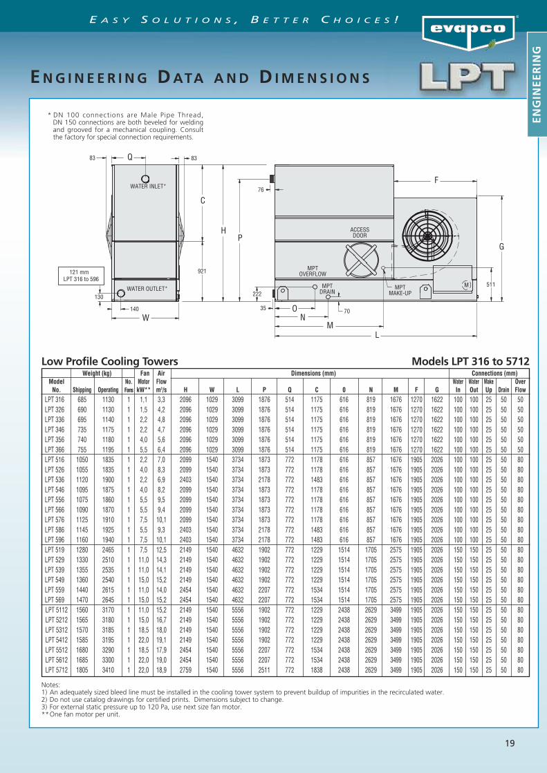
Weight (kg) Fan Air Dimensions (mm) Connections (mm)Model No. Motor Flow Water Water Make OverNo. Shipping Operating Fans kW** m3/s H W L P Q C 0 N M F G In Out Up Drain Flow
LPT 316 685 1130 1 1,1 3,3 2096 1029 3099 1876 514 1175 616 819 1676 1270 1622 100 100 25 50 50LPT 326 690 1130 1 1,5 4,2 2096 1029 3099 1876 514 1175 616 819 1676 1270 1622 100 100 25 50 50LPT 336 695 1140 1 2,2 4,8 2096 1029 3099 1876 514 1175 616 819 1676 1270 1622 100 100 25 50 50LPT 346 735 1175 1 2,2 4,7 2096 1029 3099 1876 514 1175 616 819 1676 1270 1622 100 100 25 50 50LPT 356 740 1180 1 4,0 5,6 2096 1029 3099 1876 514 1175 616 819 1676 1270 1622 100 100 25 50 50LPT 366 755 1195 1 5,5 6,4 2096 1029 3099 1876 514 1175 616 819 1676 1270 1622 100 100 25 50 50LPT 516 1050 1835 1 2,2 7,0 2099 1540 3734 1873 772 1178 616 857 1676 1905 2026 100 100 25 50 80LPT 526 1055 1835 1 4,0 8,3 2099 1540 3734 1873 772 1178 616 857 1676 1905 2026 100 100 25 50 80LPT 536 1120 1900 1 2,2 6,9 2403 1540 3734 2178 772 1483 616 857 1676 1905 2026 100 100 25 50 80LPT 546 1095 1875 1 4,0 8,2 2099 1540 3734 1873 772 1178 616 857 1676 1905 2026 100 100 25 50 80LPT 556 1075 1860 1 5,5 9,5 2099 1540 3734 1873 772 1178 616 857 1676 1905 2026 100 100 25 50 80LPT 566 1090 1870 1 5,5 9,4 2099 1540 3734 1873 772 1178 616 857 1676 1905 2026 100 100 25 50 80LPT 576 1125 1910 1 7,5 10,1 2099 1540 3734 1873 772 1178 616 857 1676 1905 2026 100 100 25 50 80LPT 586 1145 1925 1 5,5 9,3 2403 1540 3734 2178 772 1483 616 857 1676 1905 2026 100 100 25 50 80LPT 596 1160 1940 1 7,5 10,1 2403 1540 3734 2178 772 1483 616 857 1676 1905 2026 100 100 25 50 80LPT 519 1280 2465 1 7,5 12,5 2149 1540 4632 1902 772 1229 1514 1705 2575 1905 2026 150 150 25 50 80LPT 529 1330 2510 1 11,0 14,3 2149 1540 4632 1902 772 1229 1514 1705 2575 1905 2026 150 150 25 50 80LPT 539 1355 2535 1 11,0 14,1 2149 1540 4632 1902 772 1229 1514 1705 2575 1905 2026 150 150 25 50 80LPT 549 1360 2540 1 15,0 15,2 2149 1540 4632 1902 772 1229 1514 1705 2575 1905 2026 150 150 25 50 80LPT 559 1440 2615 1 11,0 14,0 2454 1540 4632 2207 772 1534 1514 1705 2575 1905 2026 150 150 25 50 80LPT 569 1470 2645 1 15,0 15,2 2454 1540 4632 2207 772 1534 1514 1705 2575 1905 2026 150 150 25 50 80LPT 5112 1560 3170 1 11,0 15,2 2149 1540 5556 1902 772 1229 2438 2629 3499 1905 2026 150 150 25 50 80LPT 5212 1565 3180 1 15,0 16,7 2149 1540 5556 1902 772 1229 2438 2629 3499 1905 2026 150 150 25 50 80LPT 5312 1570 3185 1 18,5 18,0 2149 1540 5556 1902 772 1229 2438 2629 3499 1905 2026 150 150 25 50 80LPT 5412 1585 3195 1 22,0 19,1 2149 1540 5556 1902 772 1229 2438 2629 3499 1905 2026 150 150 25 50 80LPT 5512 1680 3290 1 18,5 17,9 2454 1540 5556 2207 772 1534 2438 2629 3499 1905 2026 150 150 25 50 80LPT 5612 1685 3300 1 22,0 19,0 2454 1540 5556 2207 772 1534 2438 2629 3499 1905 2026 150 150 25 50 80LPT 5712 1805 3410 1 22,0 18,9 2759 1540 5556 2511 772 1838 2438 2629 3499 1905 2026 150 150 25 50 80
Notes:1) An adequately sized bleed line must be installed in the cooling tower system to prevent buildup of impurities in the recirculated water.2) Do not use catalog drawings for certified prints. Dimensions subject to change.3) For external static pressure up to 120 Pa, use next size fan motor.**One fan motor per unit.
M
W140
130
83 Q
921
C
HP
83
76
222
35 70ON
ML
511
G
FWATER INLET*
WATER OUTLET*
MPTOVERFLOW
MPTDRAIN
MPTMAKE-UP
ACCESSDOOR
121 mmLPT 316 to 596
ENG I N E E R I NG DATA AND D IMENS I ON S
Low Profile Cooling Towers Models LPT 316 to 5712
* DN 100 connections are Male Pipe Thread,DN 150 connections are both beveled for weldingand grooved for a mechanical coupling. Consultthe factory for special connection requirements.
ENGINEERING
E A S Y S O L U T I O N S , B E T T E R C H O I C E S !

20
Low Profile Cooling Towers Models LPT 819 to 8812
Notes:1) An adequately sized bleed line must be installed in the cooling tower system to prevent buildup of impurities in the recirculated water.2) Do not use catalog drawings for certified prints. Dimensions subject to change.3) For external static pressure up to 120 Pa, use next size fan motor.**One fan motor per unit.
Weight (kg) Fan Air Dimensions (mm) Connections (mm)Model No. Motor Flow Water Water Make OverNo. Shipping Operating Fans kW** m3/s H L P C 0 N M in Out up Drain Flow
LPT 819 1915 3455 2 15,0 23,3 2121 4632 1845 1200 1514 1718 2576 200 200 25 50 80
LPT 829 1945 3490 2 11,0 19,6 2121 4632 1845 1200 1514 1718 2576 200 200 25 50 80
LPT 839 1915 3455 2 15,0 22,1 2121 4632 1845 1200 1514 1718 2576 200 200 25 50 80
LPT 849 2025 3565 2 11,0 19,4 2426 4632 2149 1505 1514 1718 2576 200 200 25 50 80
LPT 859 1960 3500 2 18,5 23,3 2121 4632 1845 1200 1514 1718 2576 200 200 25 50 80
LPT 869 1970 3510 2 22,0 24,1 2121 4632 1845 1200 1514 1718 2576 200 200 25 50 80
LPT 879 2035 3580 2 18,5 23,0 2426 4632 2149 1505 1514 1718 2576 200 200 25 50 80
LPT 8112 2160 4305 2 18,5 27,0 2121 5556 1845 1200 2438 2616 3499 200 200 50 50 80
LPT 8212 2190 4330 2 22,0 28,1 2121 5556 1845 1200 2438 2616 3499 200 200 50 50 80
LPT 8312 2305 4445 2 30,0 31,6 2121 5556 1845 1200 2438 2616 3499 200 200 50 50 80
LPT 8412 2320 4465 2 22,0 27,7 2426 5556 2149 1505 2438 2616 3499 200 200 50 50 80
LPT 8512 2355 4495 2 37,0 32,5 2121 5556 1845 1200 2438 2616 3499 200 200 50 50 80
LPT 8612 2455 4595 2 30,0 30,5 2426 5556 2149 1505 2438 2616 3499 200 200 50 50 80
LPT 8712 2505 4645 2 37,0 32,5 2426 5556 2149 1505 2438 2616 3499 200 200 50 50 80
LPT 8812 2650 4785 2 37,0 32,4 2731 5556 2454 1810 2438 2616 3499 200 200 50 50 80
M921
C
H P
67
222
35
2388
1194
146
83 1194 83
ON
ML
67
511
2026
1905
DN 200 BFW/GROOVED INLET
DN 200 BFW/GROOVED OUTLETMPT
OVERFLOW
MPT DRAIN
(2) ACCESS DOOR
MPTMAKE-UP
ENG I N E E R I NG DATA AND D IMENS I ON S
ENGINEERING
E A S Y S O L U T I O N S , B E T T E R C H O I C E S !

21
S P E C I F I C A T I O N S
ENGINEERING
1.0 FORCED DRAFT LPT COOLING TOWER
1.1 General
Furnish and install factory assembled cooling tower of blowthrough, counterflow design with a horizontal single air sideentry and a vertical air discharge .The unit shall be completelyfactory assembled and be conform to the specifications andschedules .
The total fan power should not exceed _____ kW and the totaloverall unit dimensions should not exceed the following :Length : mmWidth : mmHeight : mm
The unit will be delivered in two parts : the bottom section(pan-fan) and the top section (heat transfer).The unit (top and bottom section) shall be joined togetherwith elastic sealer and bolted together with corrosion resist-ance fasteners.
Approved manufacturer : Evapco – model LPT________
1.2 Thermal Performance – Performance Warranty
The tower shall be capable of performing the thermal dutiesas shown in the schedule and on drawings, and its designthermal rating shall be certified by the Cooling TechnologyInstitute (C.T.I.).Only models with performance certified by CTI will beapproved.
Manufacturers performance guarantee without CTI certifica-tion for the proposed model or an independent field perform-ance test shall not be accepted.
1.3 Applicable Standards
ATC 128 Test Code for Measurement of Sound from WaterCooling Towers CTI STD 201 Standard for Thermal Performance Certificationof Evaporative Heat Rejection Equipment
1.4 Submittals
a) The manufacturer shall submit a five year history of theproposed type of cooling tower with a minimum of 10installations for similar sized equipment.
b) Shop drawings : submit shop drawings indicating dimen-sions, weight loadings and required clearances.
c) Product data : submit manufacturers technical productdata, original selection printouts and clearance require-ments.
d) Performance data : submit curves showing certified andguaranteed cooling tower performance with variation inoutdoor air wet bulb temperature at design air flow anddesign flow rate. In addition submit performance curves for 90 % and 110% of design water flow rate, indicating the cooling towertemperatures versus the ambient air wet bulb tempera-tures.
e) Complete noise data sheet for the selected cooling tower.f) Maintenance data for the cooling tower and accessories.g) The cooling tower manufacturer shall provide factory test
run certificates of the fans and fan motor.
1.5 Product Delivery – Storage and Handling
a) The contractor shall make the provisions for proper stor-age at site before installation and handle the product perthe instructions of the manufacturer.
b) Once installed provide the necessary measures that theunits remain clean and protected from any dust andmechanical damage.
1.6 Quality Assurance
a) The manufacturer shall have a quality assurance system inplace which is certified by an accredited registrar andcomplying with the requirements of ISO 9001. This is to
guarantee a consistant level of product and service quali-ty.
b) Manufacturers without ISO 9001 certification are notacceptable.
1.7 Warranty
a) The products will be warranted for a period of minmumone year from start up date or eighteen months from thedate of shipment , whichever comes first.
2.0 PRODUCT
2.1 Construction – Corrosion Resistance
a) The structure and all steel elements of the pan and casingshall be constructed of Z 725 hot dip galvanized steel forlong life and durability. Alternatives with lower zinc layerthickness and external paint or coating are not acceptedas equal.
b) The strainer shall be made of stainless steel type 304. c) During fabrication all panel edges shall be coated with a
95 % pure zinc compound.
OPTIONAL EXECUTION – BASIN IN SST 304
2.1. Construction – Corrosion Resistance
a) The structure and all steel elements of the pan up to thewater level shall be made of SST 304.
b) Alternatives with hot dip galvanized steel and epoxy coat-ings in lieu of the SST 304 are not considered equal andaccepted.
c) All other steel components and the casing shall be con-structed of Z 725 hot dip galvanized steel for long life anddurability. Alternatives with lower zinc layer thickness andexternal paint or coating are not accepted as equal.
d) The strainer shall be made of stainless steel type 304. e) During fabrication all galvanized steel panel edges shall
be coated with a 95 % pure zinc compound.
OPTIONAL EXECUTION – Complete Unit SST 304 (except moving
parts)
2.1. Construction – Corrosion Resistance
a) The structure and all steel elements shall be made of SST 304.b) Alternatives with hot dip galvanized steel and epoxy coat-
ings to replace the SST 304 are not considered equal andaccepted.
2.2 Pan / Fan section
a) The heat transfer section shall be removable from the panto provide easy handling and rigging.
b) The pan – fan section shall include fans and drives mount-ed and aligned in the factory. These items shall be locatedin the dry air stream.
c) Standard pan accessories shall included circular accessdoors , strainer(s) of anti vortex design, brass make upvalve with unsinkable plastic float arranged for easyadjustment.
2.3 Mechanical Equipment
2.3.1 Fan(s)
a) Fans shall be dynamically balanced forwardly curved cen-trifugal type fans.
b) Fan housings shall have curved inlet rings for efficient airentry and rectangular discharge cowls which extend intothe basin to increase fan efficiency and to prevent waterfrom splashing into the fans.
c) Curved inlet rings shall be made of the same material asthe cooling tower.
d) All fans will undergo a dry running test in the factoryafter being installed in the cooling tower basin.
e) The fans will be mounted on either a solid or a hollowshaft with forged bearing journals.
d) Easy to remove fan screens shall be provided to avoiddirect contact with the moving parts.
E A S Y S O L U T I O N S , B E T T E R C H O I C E S !

22
S P E C I F I C A T I O N S
2.3.2 Bearings and Drive
a) The fan shaft (s) shall be supported by heavy duty , selfaligning pillow block bearings with cast iron housings andlubrication fittings for maintenance.
b) The fan drives shall be V belt type with taper lock sheavesdesigned for 150 % of the motor nameplate horsepower.
2.3.3 Motor
a) The fan motor shall be Totally Enclosed , Fan Cooled(TEFC) , squirrel cage, ball bearing type motor.
b) The motor shall be minimum IP 55 degree of protection,Class F insulation, Service Factor 1 and selected for theappropriate cooling tower duty and the correct ambienttemperature but minimum 40°C.
c) Motor bearings shall be greased for life or external greaselines shall be provided.
d) The motor shall be mounted on an adjustable heavy dutysteel motor base.
e) The motor selection shall be selected for the appropriateexternal static pressure.
f) The motor power supply shall be _____ volts, ___ hertzand ______ phase.
2.4. Casing Section
2.4.1 Heat Transfer
a) The cooling tower fill shall be PVC (Polyvinyl Chloride) ofcross fluted design for optimum heat transfer and effi-ciency.
b) The cross fluted sheets shall be bonded together for maxi-mum strength and durability. Fill packs which are notbonded are not allowed.
c) The PVC fill shall be self extinguishing for fire resistancewith a flame spread rating of 5 per ASTM E 84 – 81a.
d) The fill shall be resistant to rot, decay or biological attack.e) The fill shall be able to withstand a water temperature of
55°C. The fill sheets will be bonded together in such a waythat the structural integrity of the fill makes the fill use-able as a working platform.
f) The cooling tower manufacturer shall be responsible forthe manufacturing and performance testing of the fill.This is to assure single source responsibility.
2.4.2 Water Distribution
a) The spray header and branches shall be constructed ofSchedule 40, Polyvinyl Chloride (PVC) pipe for corrosionresistance and shall have a steel connection to attach theexternal piping.
b) The internal tower water distribution piping shall be easi-ly removable for cleaning purposes.
c) The branches have end caps to assist with debris removal.d) The water shall be distributed over the fill by precision
molded ABS spray nozzles with large minimum 1 inch ori-fice openings and integral sludge ring to eliminate clog-ging.
e) The nozzles shall be threaded into the water distributionpiping to assure positive positioning. The nozzles arelocated on the side of the header to allow the largerdebris to flow easily through the water distribution sys-tem.
f) Each cell shall have only one hot water return inlet, other-wise the cooling tower manufacturer shall provide thenecessary extra provisions (piping, balancing valves, …) toachieve the same at no extra cost.
2.4.3 Drift Eliminators
a) The drift eliminators shall be constructed entirely inertpolyvinyl (PVC) that has been specially treated to resistultra violet light.
b) Assembled in easily handled sections , the eliminatorblades shall be spaced on 1 inch centers and shall incorpo-rate three changes in air direction to assure efficientremoval of entrained moisture from the discharge airstream.
c) The maximum drift rate shall not exceed 0,001 % of therecirculated water rate.
d) The drift eliminators shall be EuroventOM-14-2009certified.
3.0 ACCESSORIES (optional)
3.1 Electric Heaters
a) The cooling tower cold water basin shall be provided witha electric heater package to prevent freezing of the waterin the cold water basin.
b) The electric heater package includes : electric heater ele-ments and a combination of thermostat and low waterlevel cutoff.
c) The heaters shall be selected to maintain 4°C basin watertemperature at _____°C ambient
d) The heater(s) shall be ____V / ____ phase / ____ Hz electricpower supply.
3.2 Three Probe Electric Water Level Control Package
a) The cooling tower manufacturer shall provide an electricwater level control package instead of the mechanicalfloat valve arrangement.
b) The package consist of the following elements :- Multiple heavy duty stainless steel SST 316 static probesmounted in a stilling tube outside the unit. Electrodes orsensors mounted inside the unit are not accepted as thereoperation will disturbed by the moving water in thebasin. - A ABS, IP 56 case contains all the contactors for the dif-ferent level probes and willprovide a output signal of a relay for automatic fillingand one relay for alarm level.- The power supply to the control package is 24 Vac / 230Vac - ____ Hz .- A weather protected solenoid valve for the water makeup ready for Piping to a water supply with pressurebetween 140 kPa and 340 kPa.
3.3 Intake Sound Attenuation
a) The unit will be equipped with intake sound attenuationconsisting of a hot dip galvanized steel housing of thesame quality of the unit and completed with acousticalbaffles made of fiberglass material which is suitable foruse in cooling towers.
b) The intake sound attenuator is provided with large accessdoors which allow access to maintain the fans and bear-ings.
c) The intake sound attenuator is completed with a solidbottom panel beneath the cooling tower basin.
d) The cooling tower motor size must be adjusted for theadditional static pressure drop caused by the sound atten-uator.
3.4 Discharge Sound Attenuation
a) The unit will be equipped with discharge sound attenua-tion consisting of a hot dip galvanized steel housing ofthe same quality of the unit and completed with acousti-cal baffles made of fiberglass material which is suitablefor use in cooling towers.
b) The discharge sound attenuator is provided with largeaccess doors which allow access to maintain the water dis-tribution system without removing the baffles.
c) The cooling tower motor size must be adjusted for theadditional static pressure drop caused by the sound atten-uator
3.5 Vibration Switch
a) A vibration limit switch shall be installed on the mechani-cal equipment support and wired into the control panel.The purpose of this switch will be interrupt power to themotor in the event of excessive vibration.
b) The switch shall be adjustable for sensitivity, and shallrequire manual reset.
ENGINEERING
E A S Y S O L U T I O N S , B E T T E R C H O I C E S !

23
Notes:
E A S Y S O L U T I O N S , B E T T E R C H O I C E S !

Evapco Products are Manufactured Worldwide
World Headquarters /Research and Development Center
EVAPCO ManufacturingFacilities
EVAPCO, Inc.— World Headquarters & Research/Development Center
EVAPCO, Inc.World HeadquartersP.O. Box 1300Westminster, MD 21158 USAPhone: 410-756-2600Fax: 410-756-6450E-mail: [email protected]
EVAPCO East5151 Allendale LaneTaneytown, MD 21787 USAPhone: 410-756-2600Fax: 410-756-6450E-mail: [email protected]
EVAPCO Midwest1723 York RoadGreenup, IL 62428 USAPhone: 217-923-3431Fax: 217-923-3300E-mail: [email protected]
EVAPCO West1900 West Almond AvenueMadera, CA 93637 USAPhone: 559-673-2207Fax: 559-673-2378E-mail: [email protected]
EVAPCO Iowa925 Quality DriveLake View, IA 51450 USAPhone: 712-657-3223Fax: 712-657-3226
EVAPCO IowaSales & Engineering1234 Brady BoulevardOwatonna, MN 55060 USAPhone: 507-446-8005Fax: 507-446-8239E-mail: [email protected]
Refrigeration Valves &Systems CorporationA wholly owned subsidiary of EVAPCO, Inc.1520 Crosswind Dr.Bryan, TX 77808 USAPhone: 979-778-0095Fax: 979-778-0030E-mail: [email protected]
McCormack Coil Company, Inc.A wholly owned subsidiary of EVAPCO, Inc.P.O. Box 17276333 S.W. Lakeview BoulevardLake Oswego, OR 97035 USAPhone: 503-639-2137Fax: 503-639-1800E-mail: [email protected]
EvapTech, Inc.A wholly owned subsidiary of EVAPCO, Inc.8331 Nieman RoadLenexa, KS 66214 USAPhone: 913-322-5165Fax: 913-322-5166E-mail: [email protected]
Tower Components, Inc.A wholly owned subsidiary of EVAPCO, Inc.5960 US HWY 64ERamseur, NC 27316Phone: 336-824-2102Fax: 336-824-2190E-mail: [email protected]
EVAPCO Newton701 East Jourdan StreetNewton, IL 62448 USAPhone: 618-783-3433Fax: 618-783-3499E-mail: [email protected]
EVAPCO Europe, N.V.European HeadquartersIndustrieterrein Oost 40103700 Tongeren, BelgiumPhone: (32) 12-395029Fax: (32) 12-238527E-mail: [email protected]
EVAPCO Europe, S.r.l.Via Ciro Menotti 10I-20017 Passirana di Rho, Milan, ItalyPhone: (39) 02-939-9041Fax: (39) 02-935-00840E-mail: [email protected]
EVAPCO Europe, S.r.l.Via Dosso 223020 Piateda Sondrio, Italy
Flex Coil a/sA subsidiary of Evapco, Inc.Knøsgårdvej 115 9440 Aabybro, DenmarkPhone: (45) 9824-4999 Fax: (45) 9824-4990 E-mail: [email protected]
EVAPCO Europe, GmbHBovert 22, Meerbuscher Str. 64-78, Haus 5D-40670 Meerbusch, GermanyPhone: (49) 2159-69560Fax: (49) 2159-695611E-mail: [email protected]
EVAPCO S.A. (Pty.) Ltd.A licensed manufacturer of Evapco, Inc.18 Quality RoadIsando 1600, Republic of South AfricaPhone: (27) 11 392-6630Fax: (27) 11-392-6615E-mail: [email protected]
Evap Egypt Engineering Industries Co.5 Al Nasr Road St.Nasr City, Cairo, EgyptPhone: (20) 2-24022866 / (20) 2-24044997/8Fax: (20) 2-404-4667/ Mob: (20) 12-3917979E-mail: [email protected]
EVAPCO Asia/Pacific Headquarters1159 Luoning Rd. Baoshan Industrial ZoneShanghai, P. R. China, Postal Code: 200949Phone: (86) 21-6687-7786Fax: (86) 21-6687-7008E-mail: [email protected]
Evapco (Shanghai) RefrigerationEquipment Co., Ltd.1159 Louning Rd., Baoshan Industrial ZoneShanghai, P.R. China, Postal Code: 200949Phone: (86) 21-6687-7786Fax: (86) 21-6687-7008E-mail: [email protected]
Beijing EVAPCO RefrigerationEquipment Co., Ltd.Yan Qi Industrial Development DistrictHuai Rou CountyBeijing, P.R. China, Postal Code: 101407Phone: (86) 10 6166-7238Fax: (86) 10 6166-7395E-mail: [email protected]
EVAPCO Australia Pty Ltd..A licensed manufacturer of Evapco, Inc.34-42 Melbourne St.P.O. Box 436Riverstone, N.S.W. Australia 2765Phone: (61) 29 627-3322Fax: (61) 29 627-1715E-mail: [email protected]
EvapTech Asia Pacific Sdn. BhdA wholly owned subsidiary of EvapTech, Inc.IOI Business Park, 2/F Unit 21Persiaran Puchong Jaya SelatanBandar Puchong Jaya,47170 Puchong, Selangor, MalaysiaPhone: +(60-3) 8070 7255Fax: +(60-3) 8070 5731E-mail: evaptechinc.com
EVAPCO North America
EVAPCO, Inc. • P.O. Box 1300 • Westminster, MD 21158 USAPhone: +1 410-756-2600 • Fax: +1 410-756-6450 • E-mail: [email protected]
EVAPCO Europa EVAPCO Asia / Pacific
EVAPCO... Specialists in Heat Transfer Products and Services.
Visit EVAPCO’s Website at: http://www.evapco.eu
Bulletin 305-E Metric 1011