LPR Probe Selection Guide - Cosasco · LPR Probe Selection Guide (Figure 1) (Figure 2) General...
4
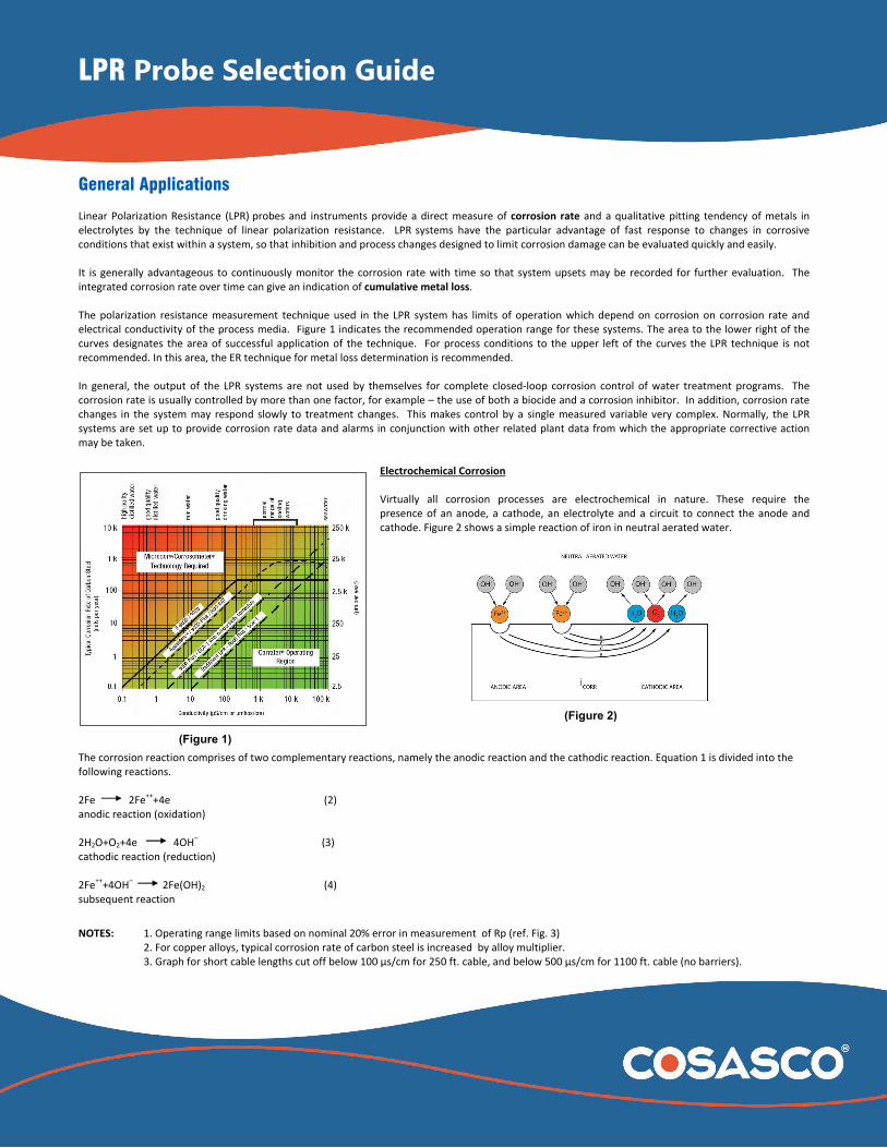
LPR Probe Selection Guide (Figure 1) (Figure 2) General Applications Linear Polarization Resistance (LPR) probes and instruments provide a direct measure of corrosion rate and a qualitative pitting tendency of metals in electrolytes by the technique of linear polarization resistance. LPR systems have the particular advantage of fast response to changes in corrosive conditions that exist within a system, so that inhibition and process changes designed to limit corrosion damage can be evaluated quickly and easily. It is generally advantageous to continuously monitor the corrosion rate with time so that system upsets may be recorded for further evaluation. The integrated corrosion rate over time can give an indication of cumulative metal loss. The polarization resistance measurement technique used in the LPR system has limits of operation which depend on corrosion on corrosion rate and electrical conductivity of the process media. Figure 1 indicates the recommended operation range for these systems. The area to the lower right of the curves designates the area of successful application of the technique. For process conditions to the upper left of the curves the LPR technique is not recommended. In this area, the ER technique for metal loss determination is recommended. In general, the output of the LPR systems are not used by themselves for complete closed‐loop corrosion control of water treatment programs. The corrosion rate is usually controlled by more than one factor, for example – the use of both a biocide and a corrosion inhibitor. In addition, corrosion rate changes in the system may respond slowly to treatment changes. This makes control by a single measured variable very complex. Normally, the LPR systems are set up to provide corrosion rate data and alarms in conjunction with other related plant data from which the appropriate corrective action may be taken. Electrochemical Corrosion Virtually all corrosion processes are electrochemical in nature. These require the presence of an anode, a cathode, an electrolyte and a circuit to connect the anode and cathode. Figure 2 shows a simple reaction of iron in neutral aerated water. The corrosion reaction comprises of two complementary reactions, namely the anodic reaction and the cathodic reaction. Equation 1 is divided into the following reactions. 2Fe 2Fe ++ +4e (2) anodic reaction (oxidation) 2H 2 O+O 2 +4e 4OH – (3) cathodic reaction (reduction) 2Fe ++ +4OH – 2Fe(OH) 2 (4) subsequent reaction NOTES: 1. Operating range limits based on nominal 20% error in measurement of Rp (ref. Fig. 3) 2. For copper alloys, typical corrosion rate of carbon steel is increased by alloy multiplier. 3. Graph for short cable lengths cut off below 100 μs/cm for 250 ft. cable, and below 500 μs/cm for 1100 ft. cable (no barriers).
Transcript of LPR Probe Selection Guide - Cosasco · LPR Probe Selection Guide (Figure 1) (Figure 2) General...
LPR Probe Selection Guide
(Figure 1)
(Figure 2)
General Applications Linear Polarization Resistance (LPR)
probes and instruments provide a direct measure of corrosion rate and a qualitative pitting tendency of metals in
electrolytes by the technique of linear polarization resistance. LPR systems have the particular advantage of fast response to changes in corrosive
conditions that exist within a system, so that inhibition and process changes designed to limit corrosion damage can be evaluated quickly and easily. It is generally advantageous to continuously monitor the corrosion rate with time so that system upsets may be recorded for further evaluation. The integrated corrosion rate over time can give an indication of cumulative metal loss. The polarization resistance measurement technique used in the LPR system has limits of operation which depend on corrosion on corrosion rate and electrical conductivity of the process media. Figure 1 indicates the recommended operation range for these systems. The area to the lower right of the curves designates the area of successful application of the technique. For process conditions to the upper left of the curves the LPR technique is not recommended. In this area, the ER technique for metal loss determination is recommended. In general, the output of the LPR systems are not used by themselves for complete closed‐loop corrosion control of water treatment programs. The corrosion rate is usually controlled by more than one factor, for example – the use of both a biocide and a corrosion inhibitor. In addition, corrosion rate changes in the system may respond slowly to treatment changes. This makes control by a single measured variable very complex. Normally, the LPR systems are set up to provide corrosion rate data and alarms in conjunction with other related plant data from which the appropriate corrective action may be taken.
Electrochemical Corrosion Virtually all corrosion processes are electrochemical in nature. These require the presence of an anode, a cathode, an electrolyte and a circuit to connect the anode and cathode. Figure 2 shows a simple reaction of iron in neutral aerated water.
The corrosion reaction comprises of two complementary reactions, namely the anodic reaction and the cathodic reaction. Equation 1 is divided into the following reactions. 2Fe 2Fe
+++4e (2)
anodic reaction (oxidation) 2H2O+O2+4e 4OH
– (3)
cathodic reaction (reduction) 2Fe
+++4OH
– 2Fe(OH)2 (4)
subsequent reaction
NOTES: 1. Operating range limits based on nominal 20% error in measurement of Rp (ref. Fig. 3) 2. For copper alloys, typical corrosion rate of carbon steel is increased by alloy multiplier. 3. Graph for short cable lengths cut off below 100 µs/cm for 250 ft. cable, and below 500 µs/cm for 1100 ft. cable (no barriers).
LPR Probe Selection Guide
At the anode, the metal “corrodes” to form metal ions which pass into solution, subsequently reacting with hydroxyl ions OH ‐ in solution to form ferrous hydroxide (“rust”). The reaction releases electrons which pass through the metal to the cathode. At the cathode various reactions may occur to absorb the electrons. In this case, water (H2O) and dissolved oxygen (O2) react to produce hydroxyl ions (OH ‐). In general corrosion, the surface of the metal comprises a large number of small anodes and cathodes forming local corrosion cells. These local cells result from small differences in the metal or process fluid. Differences in the metal can result from grain boundaries, welding, anomalies during manufacturing, etc. Differences in the process fluid, or electrolyte can result from differing concentrations of oxygen, differing temperatures or other localized differences. In general corrosion, these anodic and cathodic areas are continually changing, which cause all areas of the surface to be corroded. Theory of LPR Operation LPR probes and instruments interact with the electrochemical corrosion mechanism in order to determine the rate at which metal ions are passing into solution (corroding). If it were possible to directly measure the corrosion current density, icorr, passing between the anodic and cathodic areas it would be possible, by knowing the corrosion anodic reaction (2) above, to determine the amount or mass of metal passing into solution, i.e., corrosion rate. It is not possible to measure this directly since the anodes and cathodes exist on adjacent areas of the same piece of material. However, by using at least two electrodes of the metal under test, it is possible to apply small potentials between the electrodes and measure the resulting current. This superimposed current between the electrodes is controlled by the same anodic and cathodic corrosion reactions that control the corrosion current. If the electrodes are corroding at a high rate with metal ions passing easily into solution, a small potential applied between the electrodes produces a high current or low polarization resistance. Conversely, if the electrodes are corroding at a low rate with the ions passing only slowly into solution, a small potential applied between the electrodes produces only a low current or high polarization resistance. Hence, by applying a small potential between the metal electrodes a high current (low polarization resistance) corresponds to a high corrosion rate and low current (high polarization resistance) corresponds to low corrosion rate. As only small potentials are applied between the electrodes, the natural corrosion process is not significantly disturbed. The detailed electrochemical analysis demonstrated by Stern & Geary shows that for small applied potentials, the corrosion current density.
(5)
where B is the combination of the empirically determined anodic and cathodic Tafel Slopes (ba,bc) and Rp is the polarization resistance.
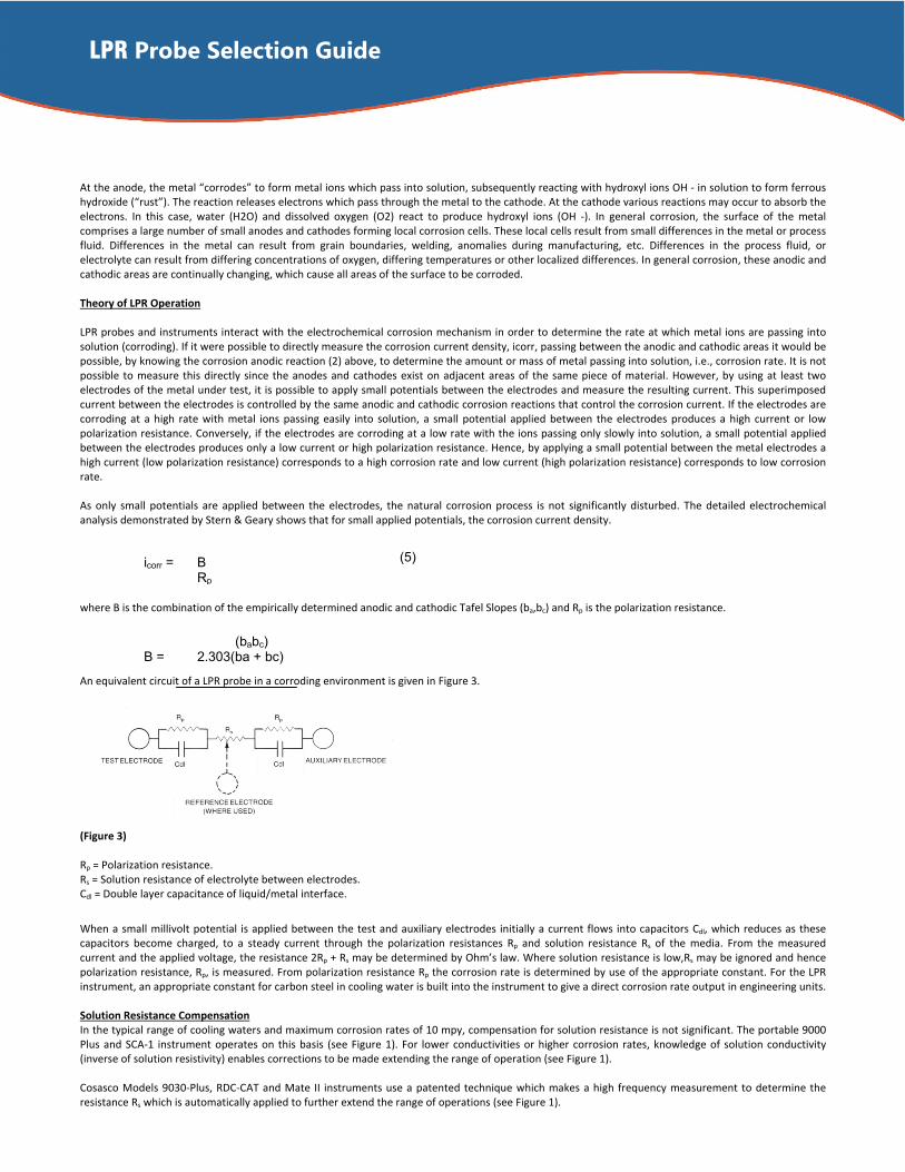
An equivalent circuit of a LPR probe in a corroding environment is given in Figure 3.
(Figure 3) Rp = Polarization resistance. Rs = Solution resistance of electrolyte between electrodes. Cdl = Double layer capacitance of liquid/metal interface.
When a small millivolt potential is applied between the test and auxiliary electrodes initially a current flows into capacitors Cdl, which reduces as these capacitors become charged, to a steady current through the polarization resistances Rp and solution resistance Rs of the media. From the measured current and the applied voltage, the resistance 2Rp + Rs may be determined by Ohm’s law. Where solution resistance is low,Rs may be ignored and hence polarization resistance, Rp, is measured. From polarization resistance Rp the corrosion rate is determined by use of the appropriate constant. For the LPR instrument, an appropriate constant for carbon steel in cooling water is built into the instrument to give a direct corrosion rate output in engineering units. Solution Resistance Compensation In the typical range of cooling waters and maximum corrosion rates of 10 mpy, compensation for solution resistance is not significant. The portable 9000 Plus and SCA‐1 instrument operates on this basis (see Figure 1). For lower conductivities or higher corrosion rates, knowledge of solution conductivity (inverse of solution resistivity) enables corrections to be made extending the range of operation (see Figure 1). Cosasco Models 9030‐Plus, RDC‐CAT and Mate II instruments use a patented technique which makes a high frequency measurement to determine the resistance Rs which is automatically applied to further extend the range of operations (see Figure 1).
icorr = B Rp
(babc) B = 2.303(ba + bc)
LPR Probe Selection Guide
(Figure 4)
(Figure 5)
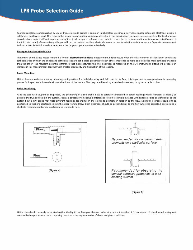
Solution resistance compensation by use of three electrode probes is common in laboratory use since a very close spaced reference electrode, usually a salt bridge capillary, is used. This reduces the proportion of solution resistance detected in the polarization resistance measurement. In the field practical considerations make it difficult to produce a sufficiently close spaced reference electrode to reduce the error from solution resistance very significantly. If the third electrode (reference) is equally spaced from the test and auxiliary electrode, no correction for solution resistance occurs. Separate measurement and correction for solution resistance extends the range of operation most effectively. Pitting (or Imbalance) Indication The pitting or imbalance measurement is a form of Electrochemical Noise measurement. Pitting occurs when there is an uneven distribution of anodic and cathodic areas or when the anodic and cathodic areas are not in close proximity to each other. This tends to make one electrode more cathodic or anodic than the other. The resultant potential difference that exists between the two electrodes is measured by the LPR instrument. Pitting will produce an increase in this measurement together with greater irregularity and fluctuation of the reading. Probe Mountings LPR probes are available in many mounting configurations for both laboratory and field use. In the field, it is important to have provision for removing probes for inspection at intervals without shutdown of the system. This may be achieved by a suitable bypass loop or by retractable probes. Probe Positioning As is the case with coupons or ER
probes, the positioning of a LPR probe must be carefully considered to obtain readings which represent as closely as
possible the true corrosion in the system. Just as a coupon often shows a different corrosion rate if it is installed with its face or side perpendicular to the system flow, a LPR probe may yield different readings depending on the electrode positions in relation to the flow. Normally, a probe should not be positioned so that one electrode shields the other from full flow. Both electrodes should be perpendicular to the flow wherever possible. Figures 4 and 5 illustrate recommended probe positioning in relation to flow.
LPR probes should normally be located so that the liquid can flow past the electrodes at a rate not less than 1 ft. per second. Probes located in stagnant areas will often produce corrosion or pitting data that is not representative of the actual plant conditions.
LPR Probe Selection Guide
Cosasco 11841 Smith Avenue Santa Fe Springs, CA 90670, USA Tel: 1‐562‐949‐0123 Email: [email protected] Web Site: www.cosasco.com
LPR‐Probe‐SG‐DS Rev. Date: 05/17/2016
©Rohrback Cosasco Systems, Inc. All rights reserved The contents of this publication are presented for information purposes only, and while effort has been made to ensure their accuracy, they are not to be construed as warranties or guarantees, express or implied, regarding the products or services described wherein or their use or applicability. We reserve the right to modify or improve the designs or specifications of our products at any time without notice. Rohrback Cosasco Systems Corrosion Monitoring Equipment is manufactured and sold under one or more of the following US Patents: 4138878, 4238298, 4338563, 4514681, 4537071, 4587479, 4605626, 4625557, 4755744, 4839580, 4841787, 4882537 5243297
Probe Ageing Wherever bare metal is exposed to a corrosive system, it corrodes at a different rate than the older part of the system until corrosion products or inhibitors deposit on the new metal surface and it comes to a state of corrosion equilibrium. Thus, the initial reading from a newly installed LPR probe will not immediately represent a true corrosion rate. The time required for the LPR probe to come to equilibrium depends on the system corrosivity. For example, an oxygen saturated brine system may require less than 20 minutes while a well inhibited cooling tower may require 24 hours or more. When several successive LPR readings are unchanged or vary about a point – as opposed to drifting – the probe is at equilibrium with the system. Thereafter, the instrument readings will show the corrosion rate occurring at the point of the probe location. Electrode Cleaning As supplied from the factory, LPR electrodes have dust‐blasted surfaces and require no further cleaning before they are used. Should electrodes become fouled with corrosion products or other material, they should be cleaned and polished to a dull shine with emery cloth or steel wool. After electrodes are cleaned, they should be thoroughly degreased in a suitable solvent and handled with a clean cloth or paper towel to prevent depositing an oily film on their surfaces.
Electrode Replacement LPR electrodes, when new, are 3/16" diameter by 1¼” long cylinders. As corrosion occurs on the electrodes, their diameter decreases, and at some point the reduced diameter begins to affect the accuracy of the corrosion and pitting readings. It is recommended that LPR electrodes be replaced when their diameter is reduced to no less than 5/32". When installing new or cleaned electrodes, they should always be handled with a clean cloth or paper towel and firmly tightened by hand. Probe Multiplier The probe multiplier is a proportionality factor that relates the electrical polarization characteristics of a probe to its corrosion rate. A calibration factor has been chosen to make the mild steel probe multiplier equal 1. of 0.5 to 3.0 with mild steel nominally at 1.0 in ordinary industrial cooling waters.
Material Multiplier ASTM A53 Pipe Grade Carbon Steel 1.00 AISI C1005‐C1010 Carbon Steel 1.00 AISI C1015 Carbon Steel 1.00 AISI C1018‐C1020 Carbon Steel 1.00 AISI C1080 Carbon Steel 1.00 AISI 4130 Alloy Steel 1.00 AISI C1022 Carbon Steel 1.00 Ingot Iron 1.00 AISI C1018 Carbon Steel 1.00 BS 970 EN 3B 1.00 AISI 304 Stainless Steel 0.89 AISI 316 Stainless Steel 0.90 AISI 316L Stainless Steel 0.90 Carpenter 20 Cb3 SS 0.98 Monel 400 Nickel 1.13 Monel K‐500 Nickel 1.04 Inconel 600 Nickel 0.95 CDA 715 70/30 Copper/Nickel 1.50 Copper 110 ETP Comm. Pure 2.00 CDA 706 90/10 Copper/Nickel 1.80 CDA 687 Alum. Brass Arsenical 1.62 CDA 642 Al Silicone Bronze 1.48 CDA 442 Admiralty Uninhibited 1.67 CDA 445 Phosphorized Admiralty 1.68 CDA 443 Arsenical Admiralty 1.67 Duronze IV 1.56 Aluminum 1100‐0 0.94 Aluminum 2024 0.86 Grades 1A, 1, 2, 3, 4 or 5 Zinc 1.29 ASTM B‐348 Grades 2‐4 Titanium 0.75 Common Lead 2.57 Zirconium 0.98