LPA Scheme for the LHC Luminosity Upgrade - CERN · PDF fileLPA Scheme for the LHC Luminosity...
47
LPA Scheme for the LHC Luminosity Upgrade Chandra Bhat, Fermilab (LARP) CERN ACCELERATOR PHYSICS FORUM August 13, 2009 CERN Chandra Bhat 1
-
Upload
nguyenkiet -
Category
Documents
-
view
230 -
download
7
Transcript of LPA Scheme for the LHC Luminosity Upgrade - CERN · PDF fileLPA Scheme for the LHC Luminosity...
LPA Scheme for
the LHC Luminosity Upgrade
Chandra Bhat, Fermilab (LARP)
CERN ACCELERATOR PHYSICS FORUM
August 13, 2009
CERN
Chandra Bhat1
Acknowledgements
Chandra Bhat 2
Frank Zimmermann,
Oliver Brüning,
SPS:
Elena Shaposhnikova
Thomas Bohl
Trevor Linnecar
Theodoros Argyropoulos
Joachim Tuckmantel
PS:
Heiko Damerau
Steven Hancock
Edgar Mahner
Fritz Caspers
Thanks also to
Humberto Cuna rom Univ. Extremadura, Cen. Uni. Merida, for providing me
ECLOUD simulations on FLAT bunches in the LHC
Outline
Motivation
Introduction Flat-bunch scheme, a short history and theory
LHC luminosity upgrade scenarios
Flat bunch Studies at CERN Beam studies in SPS and PS
Flat Bunches in the Fermilab Recycler Ring
Issues to explore
Prospects for LHC
Conclusions & Plans
Chandra Bhat3
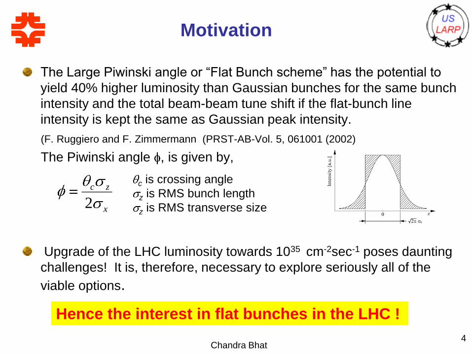
Motivation
The Large Piwinski angle or “Flat Bunch scheme” has the potential to
yield 40% higher luminosity than Gaussian bunches for the same bunch
intensity and the total beam-beam tune shift if the flat-bunch line
intensity is kept the same as Gaussian peak intensity.
(F. Ruggiero and F. Zimmermann (PRST-AB-Vol. 5, 061001 (2002)
The Piwinski angle , is given by,
Upgrade of the LHC luminosity towards 1035 cm-2sec-1 poses daunting
challenges! It is, therefore, necessary to explore seriously all of the
viable options.
Chandra Bhat4
Hence the interest in flat bunches in the LHC !
x
zc
2
c is crossing angle
z is RMS bunch length
z is RMS transverse size
Some History Time-line
Used in ISR (1972-1979)
Flat bunch applications worldwide
Fermilab Collider program: Recycler (2000-present).
We had barrier rf system since its inception (~1982).
CERN-SPS Flat bunches with barrier buckets (early
2000?)
KEK Induction Accelerator (~from 2000, Takayama’s
Group)
FAIR Project at Darmstadt is planning to use flat
bunches lots of theoretical work is being carried out
Chandra Bhat5
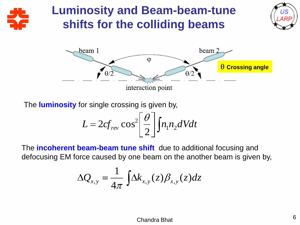
Luminosity and Beam-beam-tune
shifts for the colliding beams
Chandra Bhat 6
dVdtnncfL rev 21
2
2cos2
The luminosity for single crossing is given by,
Crossing angle
The incoherent beam-beam tune shift due to additional focusing and
defocusing EM force caused by one beam on the another beam is given by,
dzzzkQ yxyxyx )()(4
1,,,
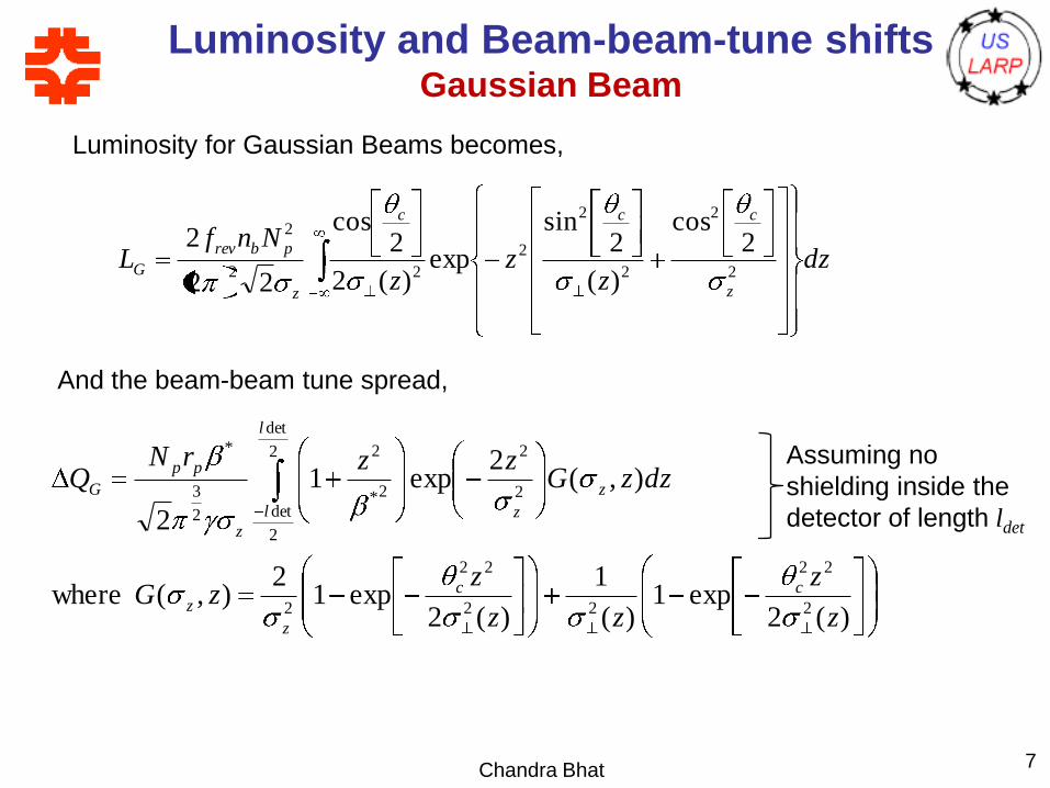
Luminosity and Beam-beam-tune shiftsGaussian Beam
Chandra Bhat 7
Assuming no
shielding inside the
detector of length ldet
Luminosity for Gaussian Beams becomes,
And the beam-beam tune spread,
Ref: 1. F. Ruggiero and F. Zimmermann PRST-AB-Vol. 5, 061001 (2002)) and
2. Heiko Damerau, “Creation and Storage of Long and Flat Bunches in the LHC”, Ph. D. Thesis 2005
dzz
zz
NnfL
z
ccc
z
pbrev
G 2
2
2
2
2
22
22
cos
)(
2sin
exp)(2
2cos
22
2
)(2exp1
)(
1
)(2exp1
2),( where
),(2
exp1
2
2
22
22
22
2
2
22
det
2
det
2*
2
2
3
*
z
z
zz
zzG
dzzGzzrN
Q
cc
z
z
z
z
l
l
z
pp
G
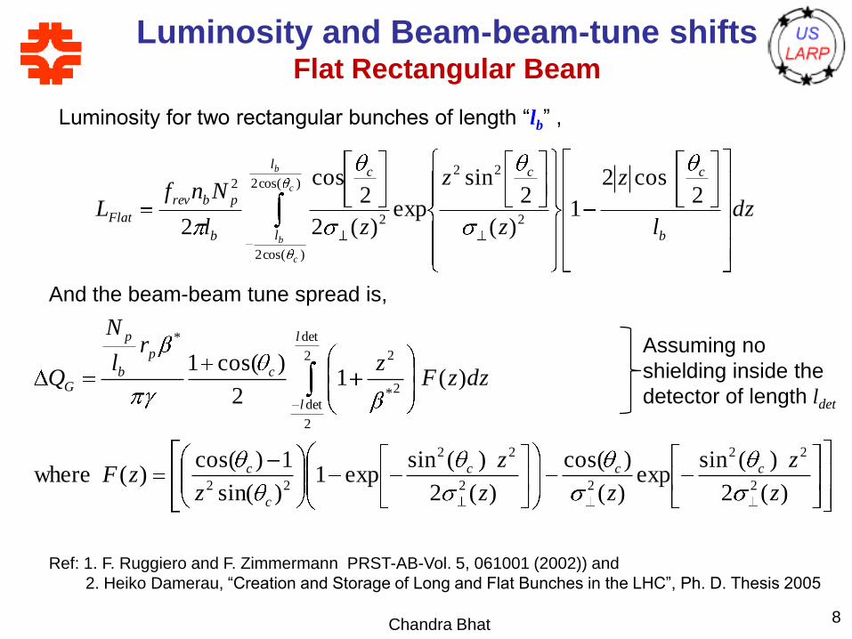
Luminosity and Beam-beam-tune shiftsFlat Rectangular Beam
Chandra Bhat 8
Luminosity for two rectangular bunches of length “lb” ,
And the beam-beam tune spread is,
Ref: 1. F. Ruggiero and F. Zimmermann PRST-AB-Vol. 5, 061001 (2002)) and
2. Heiko Damerau, “Creation and Storage of Long and Flat Bunches in the LHC”, Ph. D. Thesis 2005
Assuming no
shielding inside the
detector of length ldet
dzl
z
z
z
zl
NnfL
b
ccl
l
c
b
pbrev
Flat
c
b
c
b
2cos2
1)(
2sin
exp)(2
2cos
2 2
22)cos(2
)cos(2
2
2
)(2
)(sinexp
)(
)cos(
)(2
)(sinexp1
)sin(
1)cos()( where
)(12
)cos(1
2
22
22
22
22
2
det
2
det
2*
2
*
z
z
zz
z
zzF
dzzFz
rl
N
Q
ccc
c
c
l
l
c
p
b
p
G
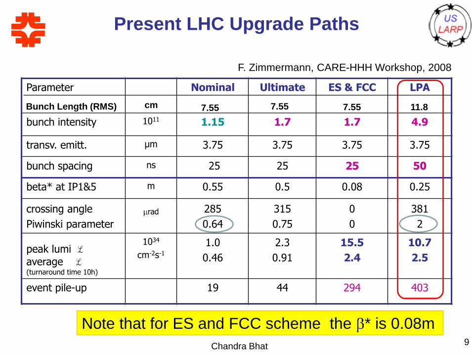
Present LHC Upgrade Paths
Chandra Bhat 9
Parameter Nominal Ultimate ES & FCC LPA
bunch intensity 1011 1.15 1.7 1.7 4.9
transv. emitt. μm 3.75 3.75 3.75 3.75
bunch spacing ns 25 25 25 50
beta* at IP1&5 m 0.55 0.5 0.08 0.25
crossing angle
Piwinski parameter
rad 285
0.64
315
0.75
0
0
381
2
peak lumi ℒaverage ℒ(turnaround time 10h)
1034
cm-2s-1
1.0
0.46
2.3
0.91
15.5
2.4
10.7
2.5
event pile-up 19 44 294 403
F. Zimmermann, CARE-HHH Workshop, 2008
Note that for ES and FCC scheme the * is 0.08m
Bunch Length (RMS) cm 7.55 7.55 7.55 11.8
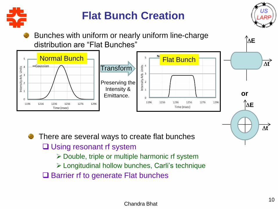
Flat Bunch Creation
Bunches with uniform or nearly uniform line-charge
distribution are “Flat Bunches”
Chandra Bhat10
Normal Bunch Flat Bunch
Preserving the
Intensity &
Emittance.
Transform
E
t
E
t
or
There are several ways to create flat bunches
Using resonant rf system
Double, triple or multiple harmonic rf system
Longitudinal hollow bunches, Carli’s technique
Barrier rf to generate Flat bunches
Flat bunches with Double Harmonic RF
References
2nd Harmonic debuncher in the LINAC, J.-P. Delahaye et. al., 11th
HEACC, Geneva, 1980.
Diagnosis of longitudinal instability in the PS Booster occurring during
dual harmonic acceleration, A.Blas et. al., PS/ RF/ Note 97-23 (MD).
Elena Shaposhnikova, CERN SL/94-19 (RF) Double harmonic rf
system; Shaposhnikova et. al., PAC2005 p, 2300.
Empty Bucket deposition in debunched beam, A. Blas, et,
al.,EPAC2000 p1528
Beam blowup by modulation near synchronous frequency with a higher
frequency rf, R. Goraby and S. Hancock, EPAC94 p 282
a) Creation of hollow bunches by redistribution of phase-space
surfaces, (C. Carli and M. Chanel, EPAC02, p233) or
b) recombination with empty bucket, C. Carli (CERN PS/2001-073).
Heiko Damerau, “Creation and Storage of Long and Flat Bunches
in the LHC”, Ph. D. Thesis 2005
RF phase jump, J. Wei et. al. (2007)
Chandra Bhat11
Chandra Bhat12
Recent Studies on Flat Bunches at
CERN
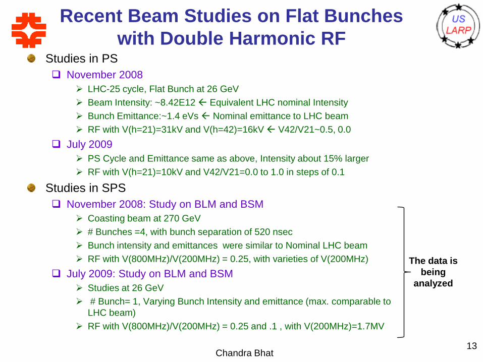
Recent Beam Studies on Flat Bunches
with Double Harmonic RF Studies in PS
November 2008
LHC-25 cycle, Flat Bunch at 26 GeV
Beam Intensity: ~8.42E12 Equivalent LHC nominal Intensity
Bunch Emittance:~1.4 eVs Nominal emittance to LHC beam
RF with V(h=21)=31kV and V(h=42)=16kV V42/V21~0.5, 0.0
July 2009
PS Cycle and Emittance same as above, Intensity about 15% larger
RF with V(h=21)=10kV and V42/V21=0.0 to 1.0 in steps of 0.1
Studies in SPS
November 2008: Study on BLM and BSM
Coasting beam at 270 GeV
# Bunches =4, with bunch separation of 520 nsec
Bunch intensity and emittances were similar to Nominal LHC beam
RF with V(800MHz)/V(200MHz) = 0.25, with varieties of V(200MHz)
July 2009: Study on BLM and BSM
Studies at 26 GeV
# Bunch= 1, Varying Bunch Intensity and emittance (max. comparable to
LHC beam)
RF with V(800MHz)/V(200MHz) = 0.25 and .1 , with V(200MHz)=1.7MV
Chandra Bhat13
The data is
being
analyzed
Chandra Bhat14
PS Studies
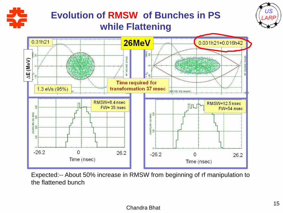
Evolution of RMSW of Bunches in PS
while Flattening
Chandra Bhat15
Expected:-- About 50% increase in RMSW from beginning of rf manipulation to
the flattened bunch
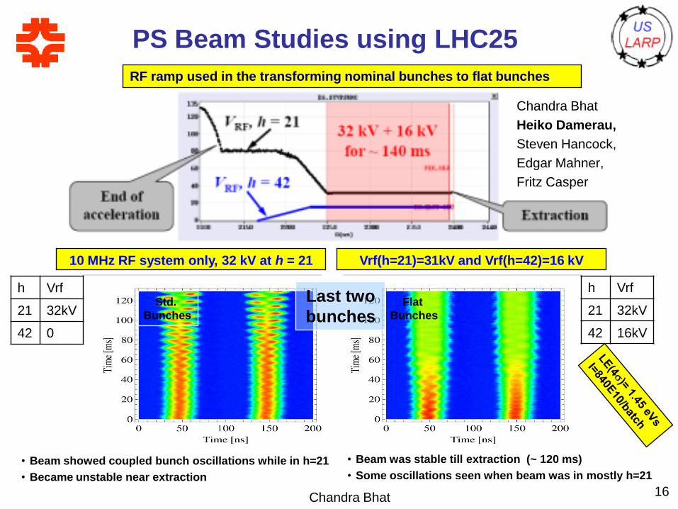
PS Beam Studies using LHC25
Chandra Bhat 16
RF ramp used in the transforming nominal bunches to flat bunches
10 MHz RF system only, 32 kV at h = 21 Vrf(h=21)=31kV and Vrf(h=42)=16 kV
Chandra Bhat
Heiko Damerau,
Steven Hancock,
Edgar Mahner,
Fritz Casper
Data at 26 GeV flat top
Bunches in single harmonic RF Bunches in Double harmonic RF
• Beam was stable till extraction (~ 120 ms)
• Some oscillations seen when beam was in mostly h=21
• Beam showed coupled bunch oscillations while in h=21
• Became unstable near extraction
Last two
bunches
h Vrf
21 32kV
42 0
h Vrf
21 32kV
42 16kV
Flat
Bunches
Std.
Bunches
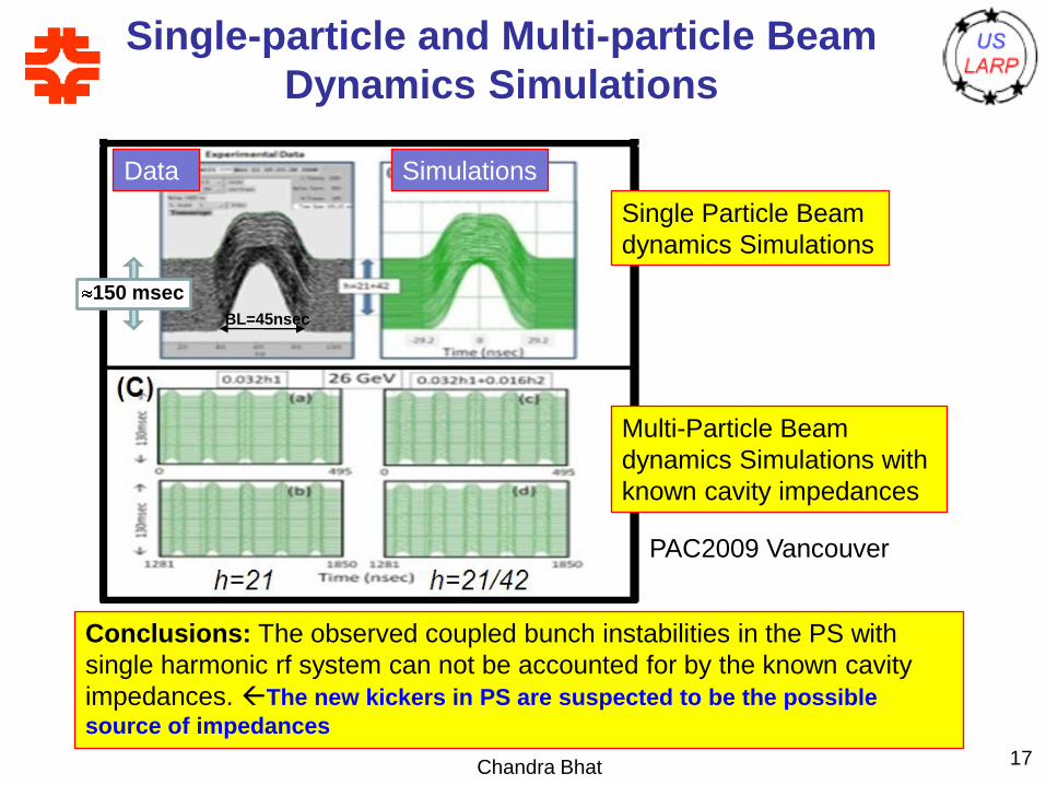
Single-particle and Multi-particle Beam
Dynamics Simulations
Chandra Bhat 17
Single Particle Beam
dynamics Simulations
Data Simulations
Multi-Particle Beam
dynamics Simulations with
known cavity impedances
PAC2009 Vancouver
Conclusions: The observed coupled bunch instabilities in the PS with
single harmonic rf system can not be accounted for by the known cavity
impedances. The new kickers in PS are suspected to be the possible
source of impedances
150 msec
BL=45nsec
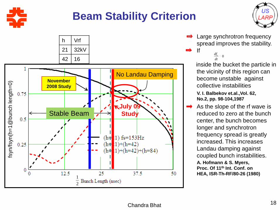
Beam Stability Criterion
Chandra Bhat 18
No Landau Damping
Stable Beam
November
2008 Study
July 09
Study
• Large synchrotron frequency
spread improves the stability.
• If
inside the bucket the particle in
the vicinity of this region can
become unstable against
collective instabilities
• As the slope of the rf wave is
reduced to zero at the bunch
center, the bunch becomes
longer and synchrotron
frequency spread is greatly
increased. This increases
Landau damping against
coupled bunch instabilities.
0dt
dfs
V. I. Balbekov et.al.,Vol. 62,
No.2, pp. 98-104,1987
A. Hofmann & S. Myers,
Proc. Of 11th Int. Conf. on
HEA, ISR-Th-RF/80-26 (1980)
2
1
h Vrf
21 32kV
42 16
fsyn
/fsyn
(h=
1@
bu
nch
len
gth
=0
)
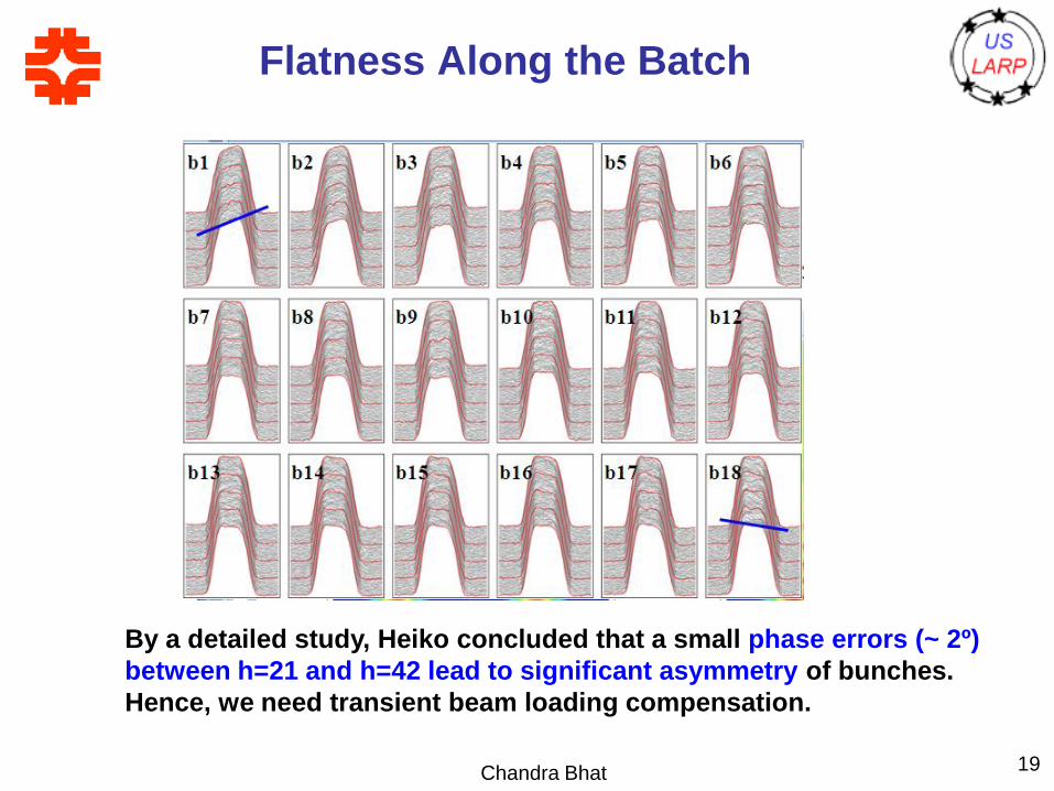
Flatness Along the Batch
Chandra Bhat 19
By a detailed study, Heiko concluded that a small phase errors (~ 2º)
between h=21 and h=42 lead to significant asymmetry of bunches.
Hence, we need transient beam loading compensation.
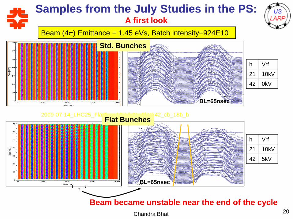
Samples from the July Studies in the PS: A first look
Chandra Bhat 20
2009-07-14_LHC25_FlatTop_10kVh21_0kVh42_cb_18b_c
2009-07-14_LHC25_FlatTop_10kVh21_5kVh42_cb_18b_b
h Vrf
21 10kV
42 0kV
h Vrf
21 10kV
42 5kV
Beam (4 ) Emittance = 1.45 eVs, Batch intensity=924E10
Beam became unstable near the end of the cycle
BL=65nsec
BL=65nsec
Flat Bunches
Std. Bunches
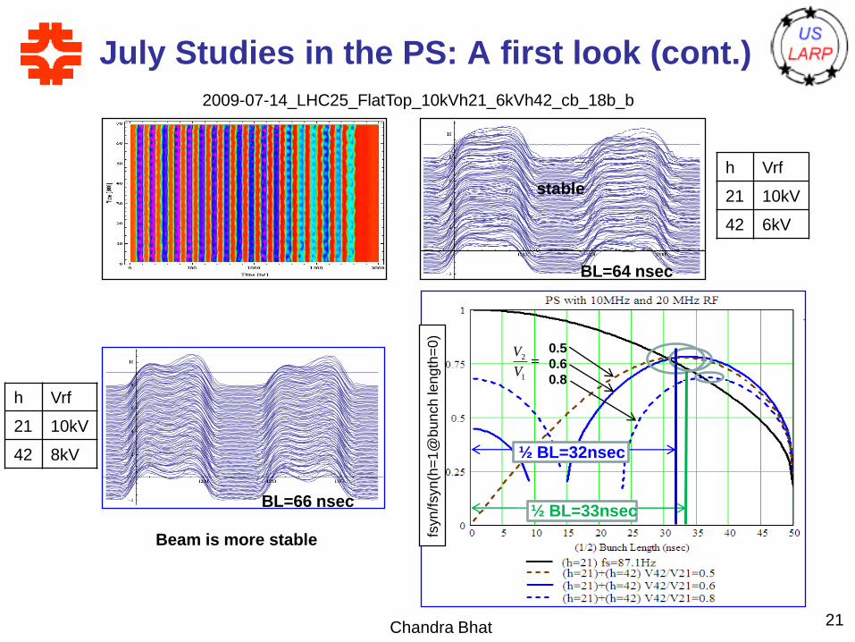
Chandra Bhat 21
2009-07-14_LHC25_FlatTop_10kVh21_6kVh42_cb_18b_b
July Studies in the PS: A first look (cont.)
h Vrf
21 10kV
42 6kV
h Vrf
21 10kV
42 8kV
½ BL=33nsecBL=66 nsec
½ BL=32nsec
BL=64 nsec
Beam is more stable
stable
fsyn
/fsyn
(h=
1@
bun
ch
len
gth
=0
)
1
2
V
V 0.5
0.6
0.8
Chandra Bhat22
Flat Bunches at the Fermilab
Recycler
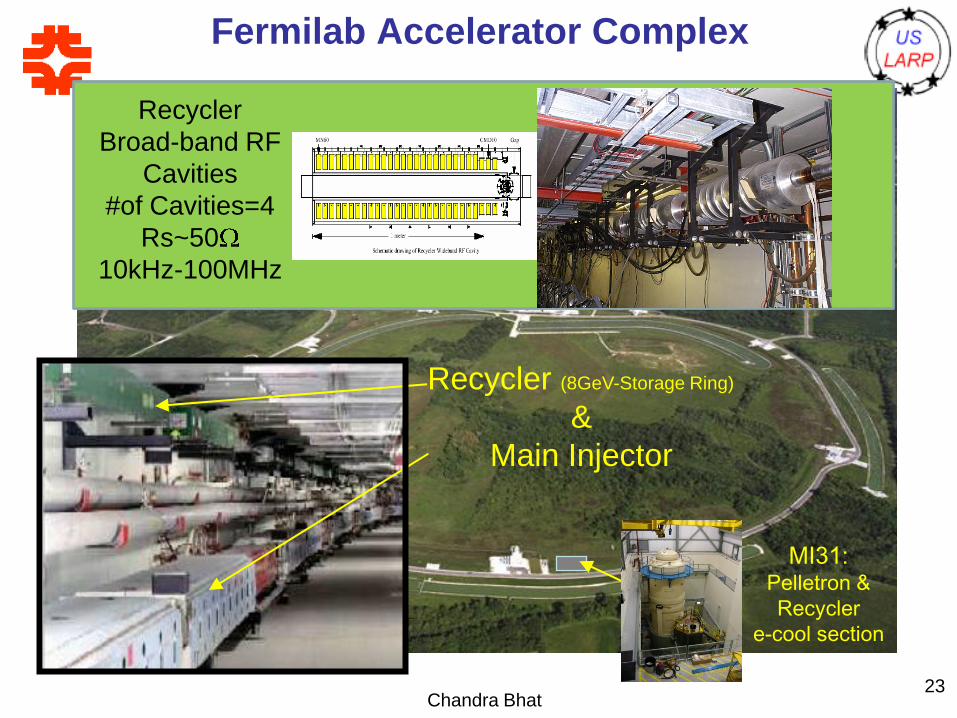
Chandra Bhat23
Tevatron
p p
Recycler (8GeV-Storage Ring)
&
Main Injector
pCDF
D0p
sourcep
1.96 TeV
Fermilab Accelerator Complex
MI31: Pelletron &
Recycler
e-cool section
Recycler
Broad-band RF
Cavities
#of Cavities=4
Rs~50
10kHz-100MHz
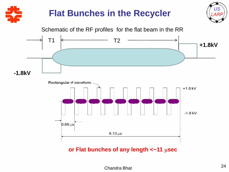
Flat Bunches in the Recycler
Chandra Bhat 24
Schematic of the RF profiles for the flat beam in the RR
+1.8kV
-1.8kV
or Flat bunches of any length <~11 sec
T1 T2
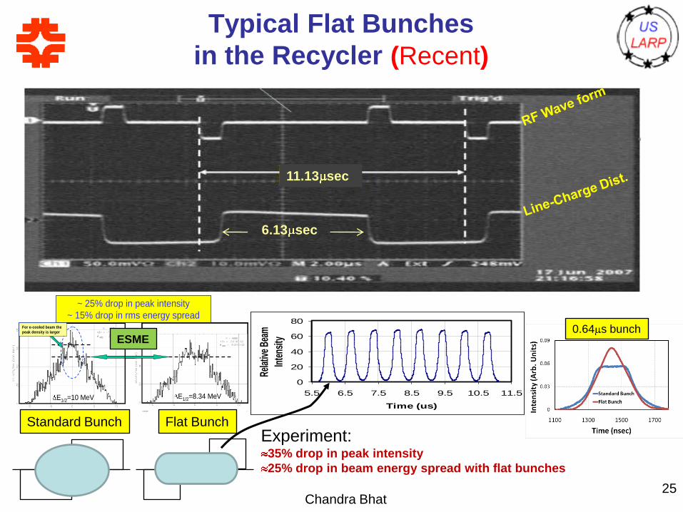
Typical Flat Bunches
in the Recycler (Recent)
Chandra Bhat
0
20
40
60
80
5.5 6.5 7.5 8.5 9.5 10.5 11.5
Time (us)
Rel
ativ
e B
eam
Inte
nsity
25
6.13 sec
11.13 sec
Experiment:35% drop in peak intensity
25% drop in beam energy spread with flat bunches
E1/2=8.34 MeVE1/2=10 MeV
~ 25% drop in peak intensity
~ 15% drop in rms energy spreadFor e-cooled beam the
peak density is larger
E1/2=8.34 MeVE1/2=10 MeV
~ 25% drop in peak intensity
~ 15% drop in rms energy spreadFor e-cooled beam the
peak density is larger
ESME
Standard Bunch Flat Bunch
0.64 s bunch
The Distortion of
the Flat Bunches in the Recycler
Chandra Bhat
Haissinski equation can not
explain this behavior
On the other hand, a careful
investigation revealed that a
sinusoidal component from the
Recycler revolution harmonic
(~89MHz) was found in the rf
vector sum of four rf stations (J.
Marriner and Chandra).
Recycler operates
Prior to 2002
RF Voltage Profile
Beam Profile of
a Flat Bunch
I=1E11
T
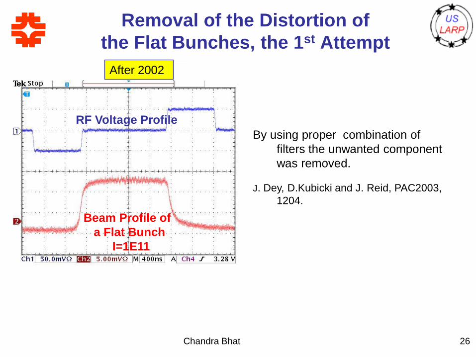
By using proper combination of filters the unwanted component was removed. J. Dey, D.Kubicki and J. Reid, PAC2003, 1204.
RF Voltage Profile
Beam Profile of
a Flat Bunch
I=1E11
After 2002
By using proper combination of
filters the unwanted component
was removed.
J. Dey, D.Kubicki and J. Reid, PAC2003,
1204.
Removal of the Distortion of
the Flat Bunches, the 1st Attempt
26
Potential Well Distortion in High
Energy Storage Rings
Chandra Bhat27
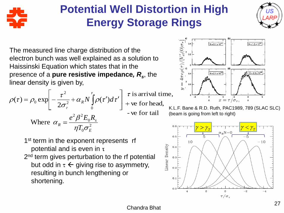
K.L.F. Bane & R.D. Ruth, PAC1989, 789 (SLAC SLC)
(beam is going from left to right)
The measured line charge distribution of the
electron bunch was well explained as a solution to
Haissinski Equation which states that in the
presence of a pure resistive impedance, Rs, the
linear density is given by,
2
0
0
22
0
2
2
0
Where
)(2
exp)(
E
sR
R
T
REe
dN
for tail ve-
head,for ve
time,arrival is
T T
1st term in the exponent represents rf
potential and is even in
2nd term gives perturbation to the rf potential
but odd in giving rise to asymmetry,
resulting in bunch lengthening or
shortening.
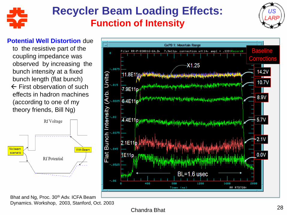
Recycler Beam Loading Effects:Function of Intensity
Chandra Bhat 28
1E11p
2.1E11p
4.4E11p
6.4E11p
11.8E11p
BL=1.6 usecFla
t B
unch I
nte
nsity (
Arb
. U
nits)
X1.25
7.9E11p
Potential Well Distortion due
to the resistive part of the
coupling impedance was
observed by increasing the
bunch intensity at a fixed
bunch length (flat bunch)
First observation of such
effects in hadron machines
(according to one of my
theory friends, Bill Ng)
Bhat and Ng, Proc. 30th Adv. ICFA Beam
Dynamics. Workshop, 2003, Stanford, Oct. 2003
Chandra Bhat 29
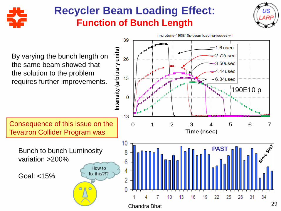
Recycler Beam Loading Effect:Function of Bunch Length
By varying the bunch length on
the same beam showed that
the solution to the problem
requires further improvements.
190E10 p
Consequence of this issue on the
Tevatron Collider Program was
Bunch to bunch Luminosity
variation >200%
Goal: <15%
PAST
How to
fix this?!?
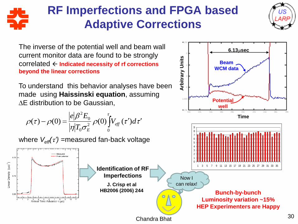
RF Imperfections and FPGA based
Adaptive Corrections
Chandra Bhat 30
The inverse of the potential well and beam wall
current monitor data are found to be strongly
correlated Indicated necessity of rf corrections
beyond the linear corrections
Arb
itra
ry U
nit
s
Time
6.13 sec
Potential
well
Beam
WCM data
0
2
0
0
2
)()0()0()( dVT
Eeeff
E
To understand this behavior analyses have been
made using Haissinski equation, assuming
E distribution to be Gaussian,
where Veff( ’) =measured fan-back voltage
Identification of RF
Imperfections
J. Crisp et al
HB2006 (2006) 244
Development of a FPGA based
adaptive correction system
M. Hu et. al, PAC2007, p 458
0
1
2
3
4
5
6
7
8
9
1 3 5 7 9 11 13 15 17 19 21 23 25 27 29 31 33 35
Bunch-by-bunch
Luminosity variation ~15%
HEP Experimenters are Happy
Now I
can relax!
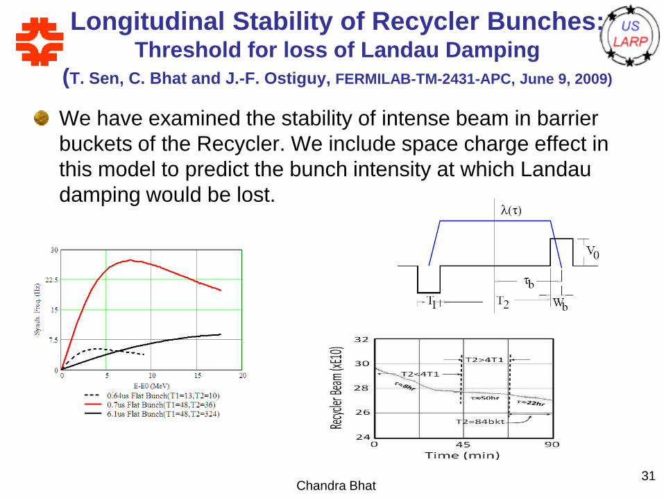
Longitudinal Stability of Recycler Bunches: Threshold for loss of Landau Damping
(T. Sen, C. Bhat and J.-F. Ostiguy, FERMILAB-TM-2431-APC, June 9, 2009)
We have examined the stability of intense beam in barrier
buckets of the Recycler. We include space charge effect in
this model to predict the bunch intensity at which Landau
damping would be lost.
Chandra Bhat31
Chandra Bhat32
Beam Studies in the SPS
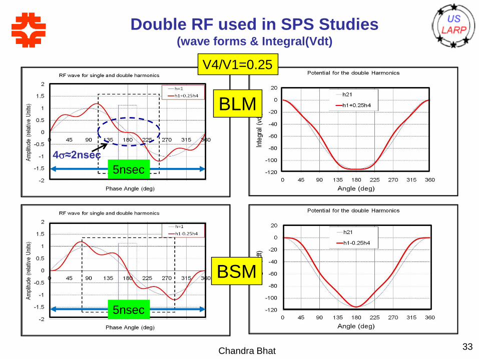
Double RF used in SPS Studies(wave forms & Integral(Vdt)
Chandra Bhat 33
BSM
BLM
5nsec
5nsec
4 ≈2nsec
V4/V1=0.25
Chandra Bhat34
Prospects for the LHC
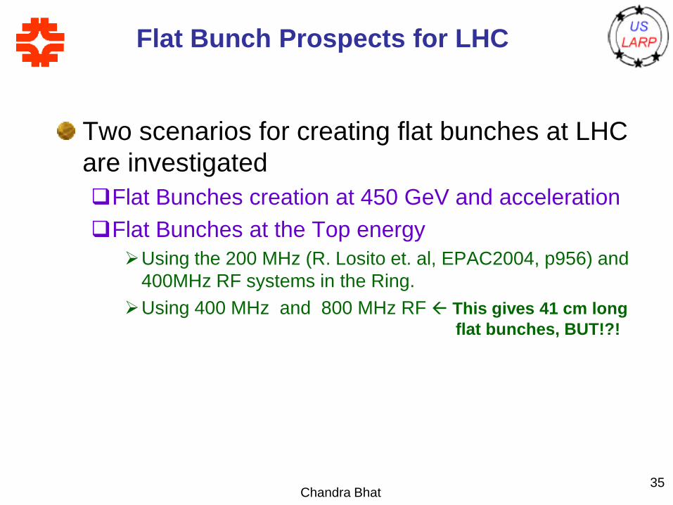
Flat Bunch Prospects for LHC
Two scenarios for creating flat bunches at LHC
are investigated
Flat Bunches creation at 450 GeV and acceleration
Flat Bunches at the Top energy
Using the 200 MHz (R. Losito et. al, EPAC2004, p956) and
400MHz RF systems in the Ring.
Using 400 MHz and 800 MHz RF This gives 41 cm long
f flat bunches, BUT!?!
Chandra Bhat35
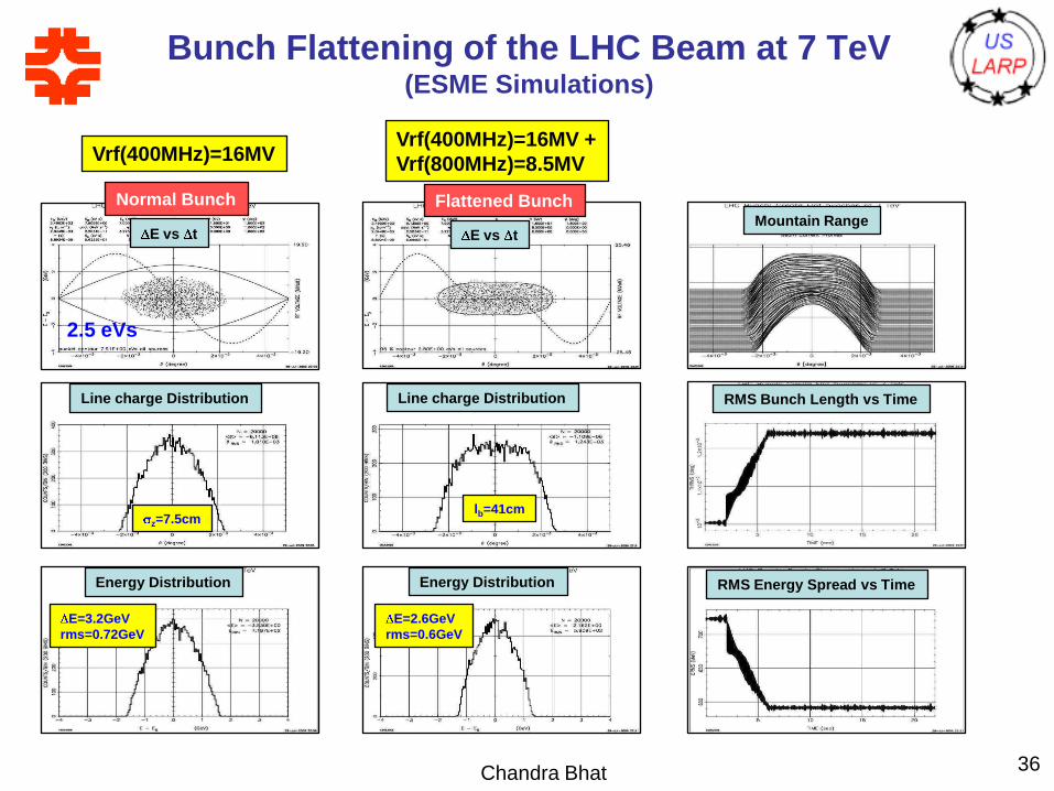
Bunch Flattening of the LHC Beam at 7 TeV(ESME Simulations)
Chandra Bhat 36
Vrf(400MHz)=16MV
E vs t
Line charge Distribution
Energy Distribution
E vs t
Line charge Distribution
Energy Distribution
Vrf(400MHz)=16MV +
Vrf(800MHz)=8.5MV
Normal Bunch Flattened BunchMountain Range
RMS Bunch Length vs Time
RMS Energy Spread vs Time
2.5 eVs
z=7.5cm
E=3.2GeV
rms=0.72GeV
lb=41cm
E=2.6GeV
rms=0.6GeV

Acceptable Flat Bunches at LHCwith 400MHz+800MHz RF
Chandra Bhat 37
No Landau Damping
for h=1+2
Stable Beam
h Vrf
35640 16MV
71280 8.5
LE=2.5eVs, Lb=41cm
2
1
Conclusions:
The 41 cm long flat bunches (2.5 eVs) with 400Mhz+800Mhz rf
systems may be susceptible to beam instability.
Chandra Bhat 38
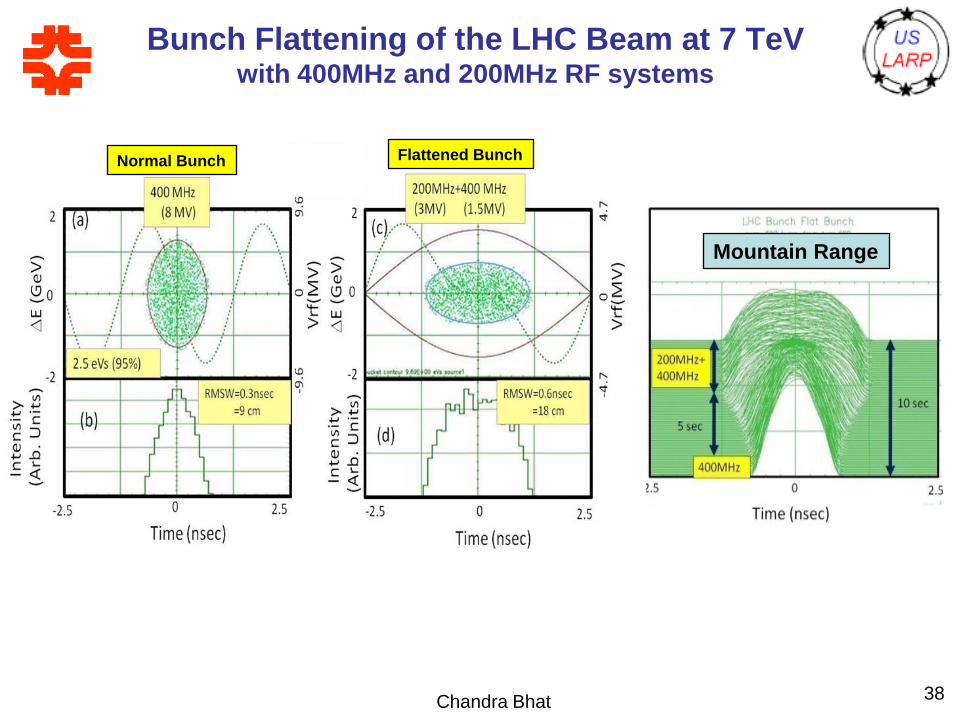
Bunch Flattening of the LHC Beam at 7 TeVwith 400MHz and 200MHz RF systems
Mountain Range
Normal Bunch Flattened Bunch
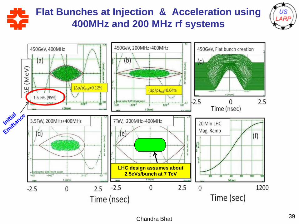
Flat Bunches at Injection & Acceleration using
400MHz and 200 MHz rf systems
Chandra Bhat 39
LHC design assumes about
2.5eVs/bunch at 7 TeV
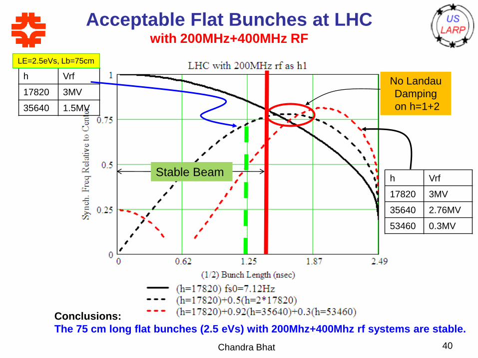
Acceptable Flat Bunches at LHCwith 200MHz+400MHz RF
Chandra Bhat 40
No Landau
Damping
on h=1+2
Stable Beam
h Vrf
17820 3MV
35640 1.5MV
LE=2.5eVs, Lb=75cm
h Vrf
17820 3MV
35640 2.76MV
53460 0.3MV
Conclusions:
The 75 cm long flat bunches (2.5 eVs) with 200Mhz+400Mhz rf systems are stable.
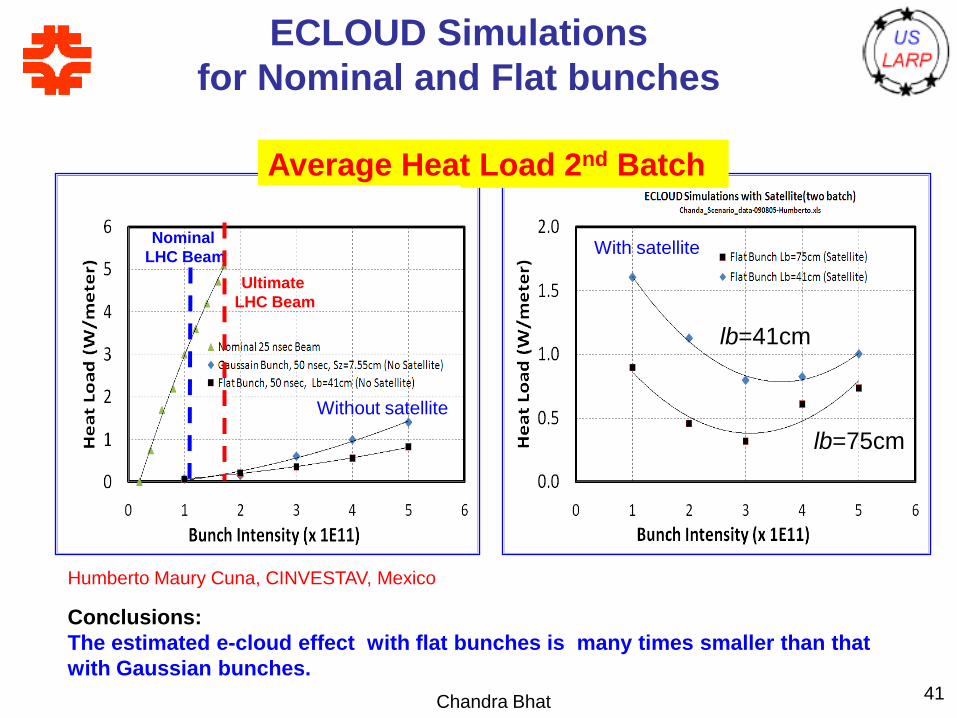
ECLOUD Simulations
for Nominal and Flat bunches
Chandra Bhat 41
Humberto Maury Cuna, CINVESTAV, Mexico
Average Heat Load 2nd Batch
Nominal
LHC Beam
Ultimate
LHC Beam
lb=75cm
lb=41cm
With satellite
Without satellite
Conclusions:
The estimated e-cloud effect with flat bunches is many times smaller than that
with Gaussian bunches.
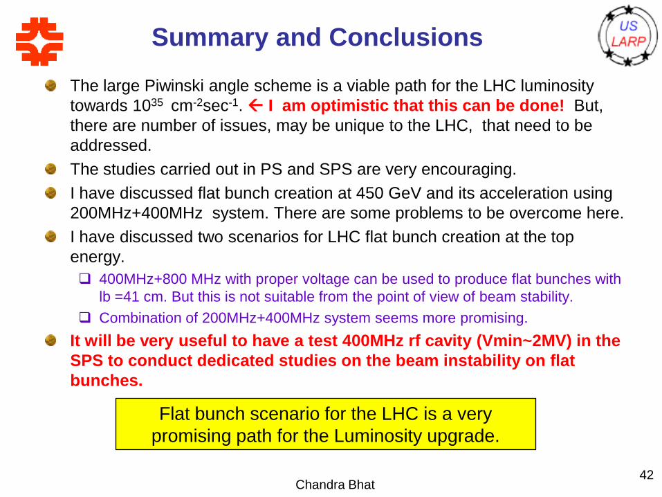
Summary and Conclusions
The large Piwinski angle scheme is a viable path for the LHC luminosity
towards 1035 cm-2sec-1. I am optimistic that this can be done! But,
there are number of issues, may be unique to the LHC, that need to be
addressed.
The studies carried out in PS and SPS are very encouraging.
I have discussed flat bunch creation at 450 GeV and its acceleration using
200MHz+400MHz system. There are some problems to be overcome here.
I have discussed two scenarios for LHC flat bunch creation at the top
energy.
400MHz+800 MHz with proper voltage can be used to produce flat bunches with
lb =41 cm. But this is not suitable from the point of view of beam stability.
Combination of 200MHz+400MHz system seems more promising.
It will be very useful to have a test 400MHz rf cavity (Vmin~2MV) in the
SPS to conduct dedicated studies on the beam instability on flat
bunches.
Chandra Bhat42
Flat bunch scenario for the LHC is a very
promising path for the Luminosity upgrade.
THANKS
Chandra Bhat43
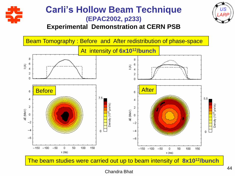
Carli’s Hollow Beam Technique(EPAC2002, p233)
Experimental Demonstration at CERN PSB
Chandra Bhat44
Beam Tomography : Before and After redistribution of phase-space
Before After
At intensity of 6x10¹²/bunch
The beam studies were carried out up to beam intensity of 8x10¹²/bunch
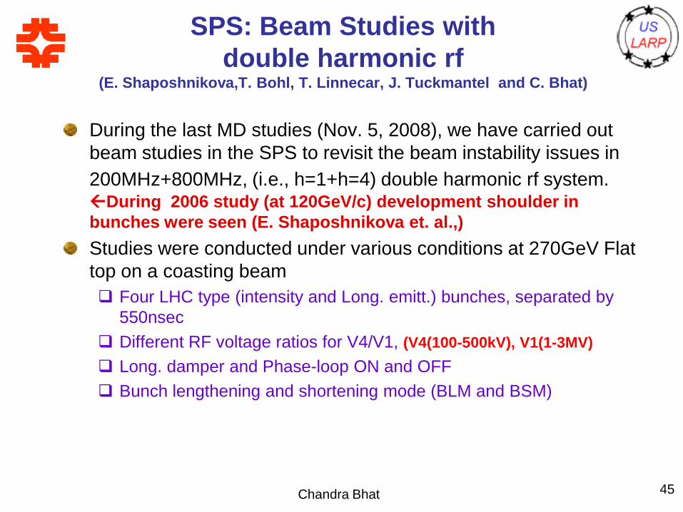
SPS: Beam Studies with
double harmonic rf(E. Shaposhnikova,T. Bohl, T. Linnecar, J. Tuckmantel and C. Bhat)
During the last MD studies (Nov. 5, 2008), we have carried out
beam studies in the SPS to revisit the beam instability issues in
200MHz+800MHz, (i.e., h=1+h=4) double harmonic rf system.During 2006 study (at 120GeV/c) development shoulder in
bunches were seen (E. Shaposhnikova et. al.,)
Studies were conducted under various conditions at 270GeV Flat
top on a coasting beam
Four LHC type (intensity and Long. emitt.) bunches, separated by
550nsec
Different RF voltage ratios for V4/V1, (V4(100-500kV), V1(1-3MV)
Long. damper and Phase-loop ON and OFF
Bunch lengthening and shortening mode (BLM and BSM)
Chandra Bhat 45
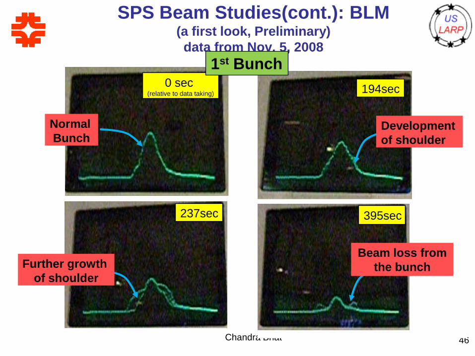
SPS Beam Studies(cont.): BLM (a first look, Preliminary)
data from Nov. 5, 2008
Chandra Bhat 46
0 sec (relative to data taking)
Normal
Bunch
194sec
Development
of shoulder
237sec
Further growth
of shoulder
395sec
Beam loss from
the bunch
1st Bunch
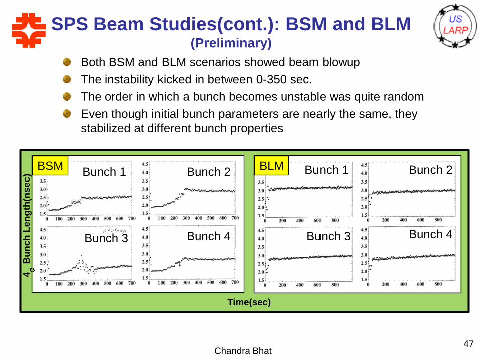
SPS Beam Studies(cont.): BSM and BLM(Preliminary)
Both BSM and BLM scenarios showed beam blowup
The instability kicked in between 0-350 sec.
The order in which a bunch becomes unstable was quite random
Even though initial bunch parameters are nearly the same, they
stabilized at different bunch properties
Chandra Bhat47
BSMBunch 1 Bunch 2
Bunch 4Bunch 3
BLM Bunch 1 Bunch 2
Bunch 4Bunch 3
4B
un
ch
Le
ng
th(n
se
c)
Time(sec)