Lp 11u Install User Guideopm Lpa 11u 5k0 10k 1us v021
46
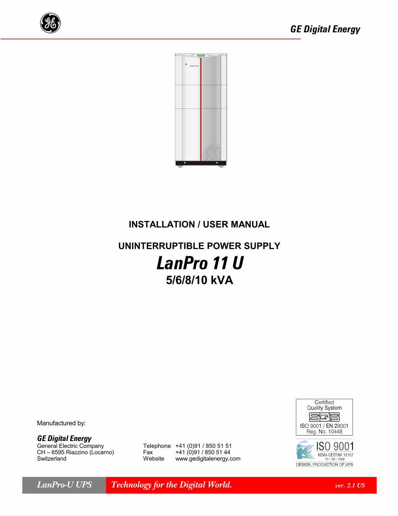
GE Digital Energy g INSTALLATION / USER MANUAL UNINTERRUPTIBLE POWER SUPPLY LanPro 11 U 5/6/8/10 kVA Manufactured by: GE Digital Energy General Electric Company Telephone +41 (0)91 / 850 51 51 CH – 6595 Riazzino (Locarno) Fax +41 (0)91 / 850 51 44 Switzerland Website www.gedigitalenergy.com Technology for the Digital World. ver. 2.1 US LanPro-U UPS
-
Upload
luis-cribari -
Category
Documents
-
view
38 -
download
0
Transcript of Lp 11u Install User Guideopm Lpa 11u 5k0 10k 1us v021
GE Digital Energy g
INSTALLATION / USER MANUAL
UNINTERRUPTIBLE POWER SUPPLY
LanPro 11 U5/6/8/10 kVA
Manufactured by:
GE Digital EnergyGeneral Electric Company Telephone +41 (0)91 / 850 51 51CH – 6595 Riazzino (Locarno) Fax +41 (0)91 / 850 51 44Switzerland Website www.gedigitalenergy.com
Technology for the Digital World. ver. 2.1 USLanPro-U UPS
���������
LX: OPM_LPA_11U_5K0_10K_1US_V021 1 GE DE LanPro-11U UPS: Installation / User Manual 2.1 (US)
GE Digital EnergygUSER MANUAL LanPro 5/6/8/10-11U UPSLX-DOCFile: OPM_LPA_11U_5K0_10K_1US_V021Software version R2.9
INSTALLATION / USER MANUALUNINTERRUPTIBLE POWER SUPPLY
LanPro® 11 U5/6/8/10kVA
PrefaceWe thank you for selecting a GE (General Electric) Digital Energy Uninterruptible Power Supply (UPS) andrecommend that you read these instructions carefully before installation and start-up of the LanPro®-U UPS.
Please keep this manual in a safe place for future reference and carefully read the important safety instructions inchapter 1 before installation of this device.
TestedGE Digital Energy is committed to quality and individually tests each LanPro®-U UPS to ensure reliableperformance for the user. All units have passed GE DE's quality control standards and conform to the tolerances inthe enclosed specifications.
About GE Digital EnergyGE Digital Energy is a leading provider of mission critical power equipment, and bridges the gap between thetraditional electricity supply and the critical power requirements of today’s businesses. GE designs, develops anddelivers extremely reliable and intelligent power solutions, from desktop UPS to self-contained premium powersystems which are supported through a global services network.
© General Electric Digital Energy. All rights reserved; reproduction in whole or in parts without permission prohibited. This manual may besubject to change; no liability can be accepted for any error or omission.LanPro®-U is a registered trademark of GE Digital Energy. Trademarks of other companies used in this document are registered trademarks oftheir respective owners.

LX: OPM_LPA_11U_5K0_10K_1US_V021 2 GE DE LanPro-11U UPS: Installation / User Manual 2.1 (US)
GE Digital EnergygCONTENTS
1 IMPORTANT SAFETY INSTRUCTIONS.....................................41.1 Save these instructions1.2 General1.3 Installation1.4 Storage1.5 Batteries
2 INTRODUCTION .........................................................................5
3 FUNCTIONAL EXPLANATION ....................................................63.1 Principles of Operation3.2 Normal Conditions3.3 Utility Failure3.4 Automatic Bypass Switch3.5 Manual Bypass Switch
4 INSTALLATION............................................................................84.1 Unpacking4.2 Package Contents4.3 Location4.4 Installation
4.4.1 Installation Procedures4.4.1.1 Standard installation procedure: Vin 208-240Vac, Vout 120/208/220/230/240Vac4.4.1.2 Installation procedure: Vin 120Vac (optional 5/6kVA), Vout 120/208/220/230/240Vac
4.4.2 Available input voltages: hardware modifications4.4.2.1 Input voltage 208 or 240Vac4.4.2.2 Input voltage 120Vac (optional, 5/6kVA only)
4.4.3 Available output voltages: hardware modifications4.4.3.1 Output voltage 208Vac4.4.3.2 Output volatge 120Vac split-phase4.4.3.3 Output voltage 220/230/240Vac4.4.3.4 Output voltage 120Vac single phase
4.4.4 Input / output voltages: Software modification4.4.5 Installation of GE DE LanPro battery extension pack(s)4.4.6 LanPro-11U series: 2 / 3 / 4 parallel operating units – additional info
4.4.6.1 Notes concerning installation of a parallel system4.4.6.2 Notes concerning starting up the parallel system4.4.6.3 Notes concerning use / maintenance of a parallel system
5 OPERATION...............................................................................215.1 Description of Front and Rear Panel5.2 Start-up5.3 Use
5.3.1 Information menu5.3.2 Status and alarm menu5.3.3 Service menu5.3.4 Setup menu
5.4 Test Screens5.4.1 Battery test, general5.4.2 Quick battery test5.4.3 Deep battery test
5.5 Other Features5.5.1 Shutdown5.5.2 Mains start5.5.3 Sleep and wake-up5.5.4 Overload protection in bypass mode5.5.5 ECO-Mode5 5.6 Auto restart5.5.7 Superior battery management

LX: OPM_LPA_11U_5K0_10K_1US_V021 3 GE DE LanPro-11U UPS: Installation / User Manual 2.1 (US)
GE Digital Energyg6 INTERFACING FEATURES.......................................................34
6.1 RS232/Contact Interface6.2 Emergency Shutdown6.3 Relay Card (optional)6.4 SNMP Interface (optional)
7 OPTIONAL FEATURES.............................................................357.1 Extended Runtime7.2 Plug-in Cards7.3 RPA-Facility (Redundant Parallel Architecture)7.4 PDM: Power Distribution Module7.5 Seismic Anchors7.6 120Vac Single Phase Option Kit
8 MAINTENANCE .........................................................................378.1 General8.2 Cooling fan8.3 Batteries8.4 Safety8.5 Storage
9 TROUBLESHOOTING ...............................................................38
10 SPECIFICATIONS......................................................................39
APPENDIX: INSTALLATION DRAWINGS
LX: OPM_LPA_11U_5K0_10K_1US_V021 4 GE DE LanPro-11U UPS: Installation / User Manual 2.1 (US)
GE Digital Energyg
1.1 Save these instructionsThis manual contains important instructions for LanPro®-11U Series UPS, that should be followed duringinstallation and maintenance of the UPS and batteries.
Before attempting to install and start up the UPS, carefully read this manual. Keep this manual nextto the UPS for future references.All servicing must be done by qualified personnel. Do not attemptto service the UPS unless you have had proper training.
CAUTION: By opening or removing covers you run the risk of exposure to dangerous voltages!
While every care has been taken to ensure the completeness and accuracy of this manual, GEDigital Energy assumes no responsibility or liability for any loss or damage resulting from the useof the information contained in this document.This document shall not be copied nor reproduced without the permission of GE Digital Energy.Due to technical improvements, some of the information contained in this manual may be changedwithout notice.
1.2 General- CAUTION: RISK OF ELECTRIC SHOCK Do not remove the cover, there are no user serviceable parts
inside. All maintenance and service work should be performed by qualified service personnel. The UPScontains batteries. The appliance outlet may be electrically live, even when the UPS is disconnected fromthe utility supply. Dangerous voltages may be present during battery operation. The batteries must bedisconnected during maintenance or service work.
- The UPS contains potentially hazardous voltages.- Do not remove fuse F4A or F4B during operation. This can result in a flame arc.
1.3 Installation- This UPS is intended to be used in a controlled environment indoors and free of conductive contaminants.- The UPS should only be powered from a single phase, three wire AC source equipped with an earth
connection.- In this manual "Earth" is represented with two different symbols:
= Field wiring equipment grounding terminal,
= Grounding terminals.- Do not install the UPS in an excessively humid environment or near water.- Avoid getting liquids or any foreign object into the UPS.- The unit must be placed in a sufficiently ventilated area; the ambient temperature should not exceed 40°C
(104°F). Optimal battery lifetime is obtained if the ambient temperature does not exceed 30°C (86°F).- It is important that the unit has adequate ventilation. Maintain air movement around and through the unit. Do
not block the air vents.- Avoid placing the unit in direct sunlight or near heat sources.- Do not plug household appliances such as electric heaters, toasters or vacuum cleaners into the UPS.- Use insulated copper input and output wiring, rated 90°C (194°F) wire size based on the ampacities given in
Tables 310-16 of the Nation Electrical code, ANSI/NFPA 70-1993. Specified in table 2 and table 3.
1.4 Storage- Store the UPS with its batteries fully charged in a dry location, storage temperature must be within -20°C
and +45°C (-4°F and 113°F).If the unit is stored for an extended period of time, the batteries must be recharged periodically, for 24 hours.Connect the unit to the utility and switch it on:
- if the storage temperature is within -20 and +30°C (-4°F and 86°F), recharge the batteries every 6 months.- if the storage temperature is within -20 and +45°C (-4°F and 113°F), recharge the batteries every 4 months.
1.5 Batteries- NOTE: Servicing of batteries should be performed or supervised by personnel knowledgeable of batteries
and the required precautions. Keep unauthorized personnel away from batteries.- When replacing the batteries, use only the same number, type and size battery.
Preferably for LanPro® 5/6-11U: Kobe HV7-12 or Panasonic LC-R127R2PLanPro® 8/10-11U: Kobe HV12-12 or Panasonic LC-RA1212P
- Proper disposal or recycling of the batteries is required. Refer to your local codes for disposal requirements.
1 - Important Safety Instructions
LX: OPM_LPA_11U_5K0_10K_1US_V021 5 GE DE LanPro-11U UPS: Installation / User Manual 2.1 (US)
GE Digital Energyg- CAUTION: Never dispose of batteries in a fire. The batteries may explode.- CAUTION: Do not open or mutilate batteries. Released electrolyte is harmful to the skin and eyes. It may be
toxic. If exposed to electrolyte, wash immediately with plenty of water.- Avoid charging in a sealed container.- CAUTION: A battery can present a risk of electrical shock and high short circuit current. The following
precautions should be observed when working on batteries:• Remove watches, rings or other metal objects.• Use tools with insulated handles.• Wear rubber gloves and boots.• Do not lay tools or metal parts on top of batteries.• Disconnect charging source prior ro connecting or disconnect battery terminals.• Determine if the battery is inadvertently grounded. If inadvertently grounded, remove source of ground.
Contact with any part of a grounded battery can result in electrical shock. The likelihood of such shockwill be reduced if such grounds are removed during installation and maintenance.
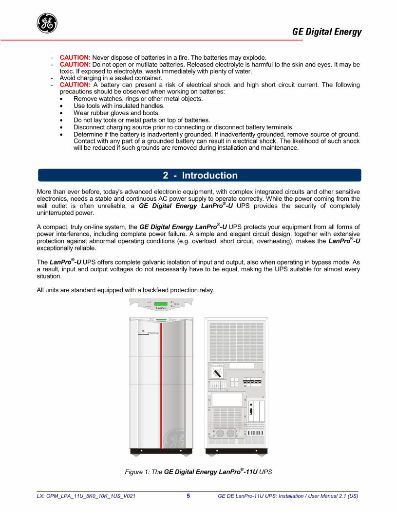
More than ever before, today's advanced electronic equipment, with complex integrated circuits and other sensitiveelectronics, needs a stable and continuous AC power supply to operate correctly. While the power coming from thewall outlet is often unreliable, a GE Digital Energy LanPro®-U UPS provides the security of completelyuninterrupted power.
A compact, truly on-line system, the GE Digital Energy LanPro®-U UPS protects your equipment from all forms ofpower interference, including complete power failure. A simple and elegant circuit design, together with extensiveprotection against abnormal operating conditions (e.g. overload, short circuit, overheating), makes the LanPro®-Uexceptionally reliable.
The LanPro®-U UPS offers complete galvanic isolation of input and output, also when operating in bypass mode. Asa result, input and output voltages do not necessarily have to be equal, making the UPS suitable for almost everysituation.
All units are standard equipped with a backfeed protection relay.
Figure 1: The GE Digital Energy LanPro®-11U UPS
������������
2 - Introduction
LX: OPM_LPA_11U_5K0_10K_1US_V021 6 GE DE LanPro-11U UPS: Installation / User Manual 2.1 (US)
GE Digital Energyg
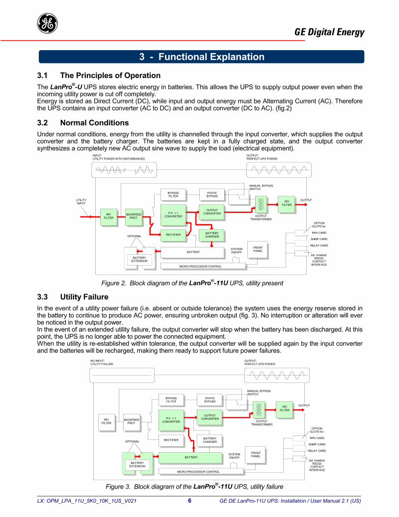
3.1 The Principles of OperationThe LanPro®-U UPS stores electric energy in batteries. This allows the UPS to supply output power even when theincoming utility power is cut off completely.Energy is stored as Direct Current (DC), while input and output energy must be Alternating Current (AC). Thereforethe UPS contains an input converter (AC to DC) and an output converter (DC to AC). (fig.2)
3.2 Normal ConditionsUnder normal conditions, energy from the utility is channelled through the input converter, which supplies the outputconverter and the battery charger. The batteries are kept in a fully charged state, and the output convertersynthesizes a completely new AC output sine wave to supply the load (electrical equipment).
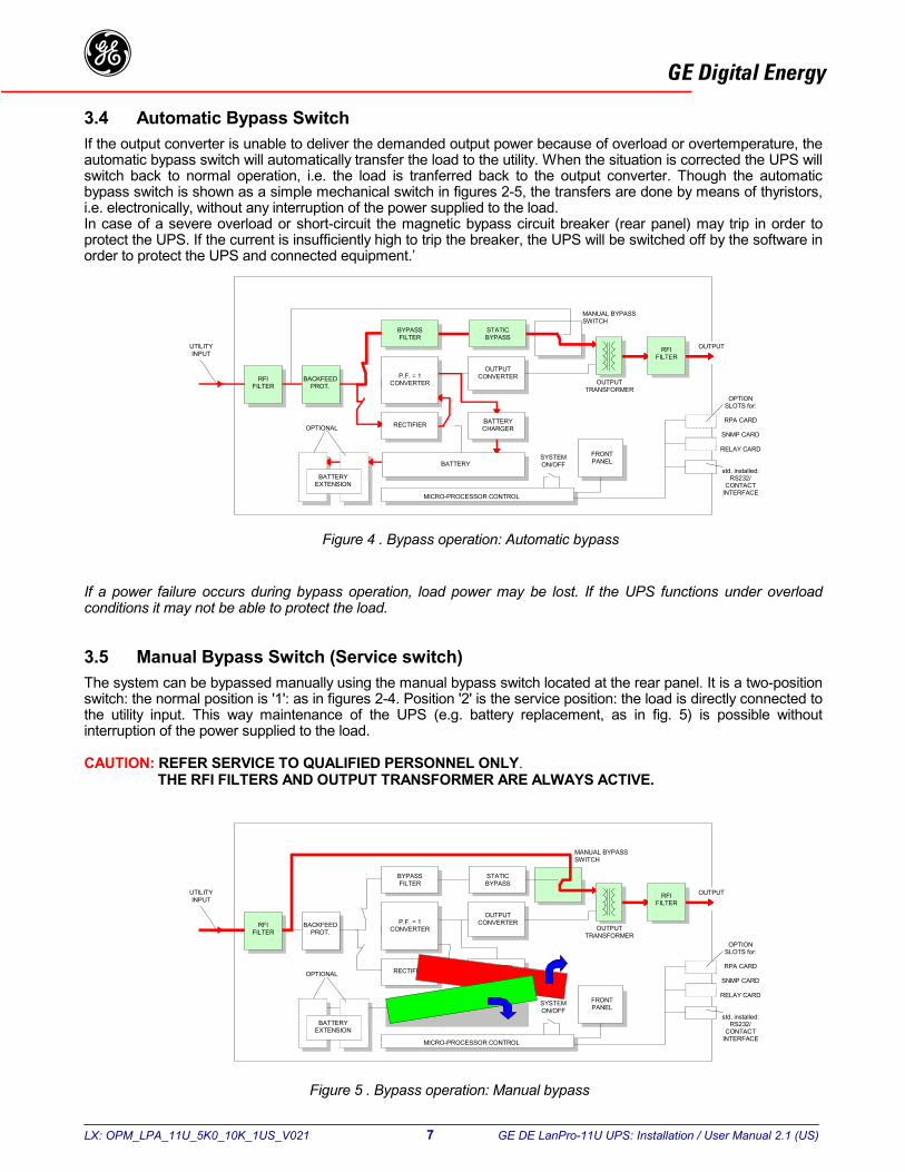
3.3 Utility FailureIn the event of a utility power failure (i.e. absent or outside tolerance) the system uses the energy reserve stored inthe battery to continue to produce AC power, ensuring unbroken output (fig. 3). No interruption or alteration will everbe noticed in the output power.In the event of an extended utility failure, the output converter will stop when the battery has been discharged. At thispoint, the UPS is no longer able to power the connected equipment.When the utility is re-established within tolerance, the output converter will be supplied again by the input converterand the batteries will be recharged, making them ready to support future power failures.
OUTPUT:PERFECT UPS POWER
OUTPUT
INPUT:UTILITY POWER WITH DISTURBANCES
RFIFILTER
P.F. = 1CONVERTER
BYPASSFILTER
STATICBYPASS
OUTPUTCONVERTER
BATTERYCHARGERRECTIFIEROPTIONAL
BATTERYEXTENSION
MICRO-PROCESSOR CONTROL
BATTERYSYSTEMON/OFF
FRONTPANEL
OUTPUTTRANSFORMER
RFIFILTER
OPTIONSLOTS for:
RPA CARD
SNMP CARD
RELAY CARD
std. installed:RS232/
CONTACTINTERFACE
UTILITYINPUT
MANUAL BYPASSSWITCH
BACKFEEDPROT.
Figure 2. Block diagram of the LanPro®-11U UPS, utility present
OUTPUT:PERFECT UPS POWER
OUTPUT
NO INPUT:UTILITY FAILURE
RFIFILTER
P.F. = 1CONVERTER
BYPASSFILTER
STATICBYPASS
OUTPUTCONVERTER
BATTERYCHARGERRECTIFIEROPTIONAL
BATTERYEXTENSION
MICRO-PROCESSOR CONTROL
BATTERYSYSTEMON/OFF
FRONTPANEL
OUTPUTTRANSFORMER
RFIFILTER
MANUAL BYPASSSWITCH
BACKFEEDPROT.
OPTIONSLOTS for:
RPA CARD
SNMP CARD
RELAY CARD
std. installed:RS232/
CONTACTINTERFACE
Figure 3. Block diagram of the LanPro®-11U UPS, utility failure
3 - Functional Explanation
LX: OPM_LPA_11U_5K0_10K_1US_V021 7 GE DE LanPro-11U UPS: Installation / User Manual 2.1 (US)
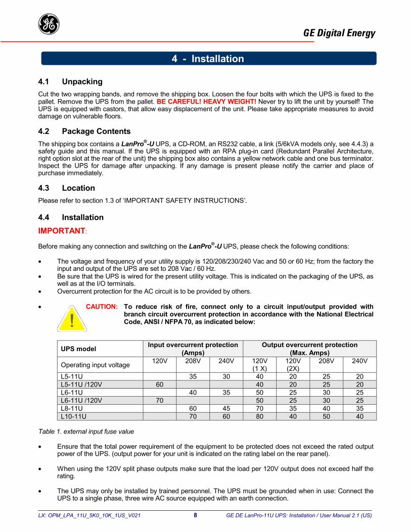
GE Digital Energyg3.4 Automatic Bypass SwitchIf the output converter is unable to deliver the demanded output power because of overload or overtemperature, theautomatic bypass switch will automatically transfer the load to the utility. When the situation is corrected the UPS willswitch back to normal operation, i.e. the load is tranferred back to the output converter. Though the automaticbypass switch is shown as a simple mechanical switch in figures 2-5, the transfers are done by means of thyristors,i.e. electronically, without any interruption of the power supplied to the load.In case of a severe overload or short-circuit the magnetic bypass circuit breaker (rear panel) may trip in order toprotect the UPS. If the current is insufficiently high to trip the breaker, the UPS will be switched off by the software inorder to protect the UPS and connected equipment.’
If a power failure occurs during bypass operation, load power may be lost. If the UPS functions under overloadconditions it may not be able to protect the load.
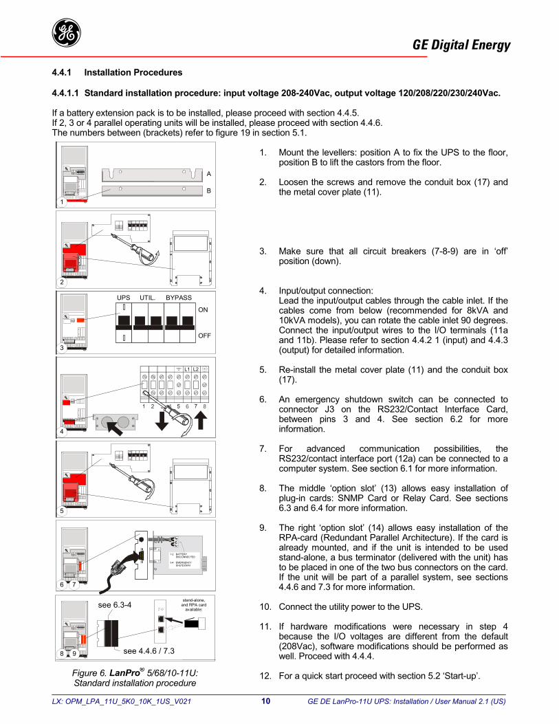
3.5 Manual Bypass Switch (Service switch)The system can be bypassed manually using the manual bypass switch located at the rear panel. It is a two-positionswitch: the normal position is '1': as in figures 2-4. Position '2' is the service position: the load is directly connected tothe utility input. This way maintenance of the UPS (e.g. battery replacement, as in fig. 5) is possible withoutinterruption of the power supplied to the load.
CAUTION: REFER SERVICE TO QUALIFIED PERSONNEL ONLY.THE RFI FILTERS AND OUTPUT TRANSFORMER ARE ALWAYS ACTIVE.
Figure 4 . Bypass operation: Automatic bypass
Figure 5 . Bypass operation: Manual bypass
OUTPUT
RFIFILTER
BYPASSFILTER
STATICBYPASS
OUTPUTCONVERTER
BATTERYCHARGERRECTIFIEROPTIONAL
BATTERYEXTENSION
MICRO-PROCESSOR CONTROL
BATTERYSYSTEMON/OFF
FRONTPANEL
OUTPUTTRANSFORMER
RFIFILTER
UTILITYINPUT
MANUAL BYPASSSWITCH
BACKFEEDPROT.
P.F. = 1CONVERTER
OPTIONSLOTS for:
RPA CARD
SNMP CARD
RELAY CARD
std. installed:RS232/
CONTACTINTERFACE
OUTPUT
BYPASSFILTER
STATICBYPASS
OUTPUTCONVERTER
BATTERYCHARGERRECTIFIEROPTIONAL
BATTERYEXTENSION
MICRO-PROCESSOR CONTROL
SYSTEMON/OFF
FRONTPANEL
OUTPUTTRANSFORMER
RFIFILTER
UTILITYINPUT
MANUAL BYPASSSWITCH
BACKFEEDPROT.
P.F. = 1CONVERTERRFI
FILTER
OPTIONSLOTS for:
RPA CARD
SNMP CARD
RELAY CARD
std. installed:RS232/
CONTACTINTERFACE
LX: OPM_LPA_11U_5K0_10K_1US_V021 8 GE DE LanPro-11U UPS: Installation / User Manual 2.1 (US)
GE Digital Energyg
4.1 UnpackingCut the two wrapping bands, and remove the shipping box. Loosen the four bolts with which the UPS is fixed to thepallet. Remove the UPS from the pallet. BE CAREFUL! HEAVY WEIGHT! Never try to lift the unit by yourself! TheUPS is equipped with castors, that allow easy displacement of the unit. Please take appropriate measures to avoiddamage on vulnerable floors.
4.2 Package ContentsThe shipping box contains a LanPro®-U UPS, a CD-ROM, an RS232 cable, a link (5/6kVA models only, see 4.4.3) asafety guide and this manual. If the UPS is equipped with an RPA plug-in card (Redundant Parallel Architecture,right option slot at the rear of the unit) the shipping box also contains a yellow network cable and one bus terminator.Inspect the UPS for damage after unpacking. If any damage is present please notify the carrier and place ofpurchase immediately.
4.3 LocationPlease refer to section 1.3 of ‘IMPORTANT SAFETY INSTRUCTIONS’.
4.4 InstallationIMPORTANT:
Before making any connection and switching on the LanPro®-U UPS, please check the following conditions:
• The voltage and frequency of your utility supply is 120/208/230/240 Vac and 50 or 60 Hz; from the factory theinput and output of the UPS are set to 208 Vac / 60 Hz.
• Be sure that the UPS is wired for the present utility voltage. This is indicated on the packaging of the UPS, aswell as at the I/O terminals.
• Overcurrent protection for the AC circuit is to be provided by others.
• CAUTION: To reduce risk of fire, connect only to a circuit input/output provided withbranch circuit overcurrent protection in accordance with the National ElectricalCode, ANSI / NFPA 70, as indicated below:
UPS model Input overcurrent protection(Amps)
Output overcurrent protection(Max. Amps)
Operating input voltage 120V 208V 240V 120V(1 X)
120V(2X)
208V 240V
L5-11U 35 30 40 20 25 20L5-11U /120V 60 40 20 25 20L6-11U 40 35 50 25 30 25L6-11U /120V 70 50 25 30 25L8-11U 60 45 70 35 40 35L10-11U 70 60 80 40 50 40
Table 1. external input fuse value
• Ensure that the total power requirement of the equipment to be protected does not exceed the rated outputpower of the UPS. (output power for your unit is indicated on the rating label on the rear panel).
• When using the 120V split phase outputs make sure that the load per 120V output does not exceed half therating.
• The UPS may only be installed by trained personnel. The UPS must be grounded when in use: Connect theUPS to a single phase, three wire AC source equipped with an earth connection.
4 - Installation

LX: OPM_LPA_11U_5K0_10K_1US_V021 9 GE DE LanPro-11U UPS: Installation / User Manual 2.1 (US)
GE Digital Energyg• Use insulated copper input and output wiring, rated 90°C derated to 40°C wire size based on the ampacities
given in Tables 310-16 of the National Electrical code, ANSI/NFPA 70-1993.
This wiring shall have the following minimum sizes:
INPUT WIRING:Utility voltage
UPS model 120V 208V 240VL5-11U 6 AWG 10 AWG 10 AWGL6-11U 4 AWG 8 AWG 10 AWGL8-11U N/A 6 AWG 8 AWGL10-11U N/A 4 AWG 6 AWG
Table 2. Input wiring
OUTPUT WIRING:Output voltage
UPS model 120V 208V 240VL5-11U 8 AWG 10 AWG 10 AWGL6-11U 8 AWG 10 AWG 10 AWGL8-11U 6 AWG 8 AWG 8 AWGL10-11U 4 AWG 8 AWG 8 AWG
Table 3. Output wiring
TIGHTENING TORQUE FORCE:UPS model Tightening torque forceL5/6-11U/120V 22 Lbs/inchAll other models 18-20 Lbs/inch
Table 4. Tightening torque force
LX: OPM_LPA_11U_5K0_10K_1US_V021 10 GE DE LanPro-11U UPS: Installation / User Manual 2.1 (US)
GE Digital Energyg4.4.1 Installation Procedures
4.4.1.1 Standard installation procedure: input voltage 208-240Vac, output voltage 120/208/220/230/240Vac.
If a battery extension pack is to be installed, please proceed with section 4.4.5.If 2, 3 or 4 parallel operating units will be installed, please proceed with section 4.4.6.The numbers between (brackets) refer to figure 19 in section 5.1.
1. Mount the levellers: position A to fix the UPS to the floor,position B to lift the castors from the floor.
2. Loosen the screws and remove the conduit box (17) andthe metal cover plate (11).
3. Make sure that all circuit breakers (7-8-9) are in ‘off’position (down).
4. Input/output connection:Lead the input/output cables through the cable inlet. If thecables come from below (recommended for 8kVA and10kVA models), you can rotate the cable inlet 90 degrees.Connect the input/output wires to the I/O terminals (11aand 11b). Please refer to section 4.4.2 1 (input) and 4.4.3(output) for detailed information.
5. Re-install the metal cover plate (11) and the conduit box(17).
6. An emergency shutdown switch can be connected toconnector J3 on the RS232/Contact Interface Card,between pins 3 and 4. See section 6.2 for moreinformation.
7. For advanced communication possibilities, theRS232/contact interface port (12a) can be connected to acomputer system. See section 6.1 for more information.
8. The middle ‘option slot’ (13) allows easy installation ofplug-in cards: SNMP Card or Relay Card. See sections6.3 and 6.4 for more information.
9. The right ‘option slot’ (14) allows easy installation of theRPA-card (Redundant Parallel Architecture). If the card isalready mounted, and if the unit is intended to be usedstand-alone, a bus terminator (delivered with the unit) hasto be placed in one of the two bus connectors on the card.If the unit will be part of a parallel system, see sections4.4.6 and 7.3 for more information.
10. Connect the utility power to the UPS.
11. If hardware modifications were necessary in step 4because the I/O voltages are different from the default(208Vac), software modifications should be performed aswell. Proceed with 4.4.4.
12. For a quick start proceed with section 5.2 ‘Start-up’.Figure 6. LanPro® 5/68/10-11U:Standard installation procedure
1
A
B
2
3
UPS UTIL. BYPASS
ON
OFF
L1 L2
4
5
6 7
8 9
1-2 BATTERYDISCONNECTED
3-4 EMERGENCYSHUTDOWN
see 6.3-4
see 4.4.6 / 7.3
stand-alone,and RPA card
available:

LX: OPM_LPA_11U_5K0_10K_1US_V021 11 GE DE LanPro-11U UPS: Installation / User Manual 2.1 (US)
GE Digital Energyg4.4.1.2 Installation procedure:
input voltage 120Vac (optional, 5-6kVA only), output voltage 120/208/220/230/240Vac.If a battery extension pack is to be installed, please proceed with section 4.4.5.If 2, 3 or 4 parallel operating units will be installed, please proceed with section 4.4.6.The numbers between (brackets) refer to figure 19 and 20 in section 5.1.
1. Mount the levellers: position A to fix the UPS to the floor,position B to lift the castors from the floor. Please refer tofigure 6, step 1.
2. Loosen the screws and remove the conduit boxes (17, 2x)and the cover plate (11).
3. Make sure that all circuit breakers (7-8-9) are in ‘off’position (down). Please refer to fig. 6, step 3.
4. Input/output connection:Lead the input/output cables through the cable inlet. If thecables come from below (recommended for 8kVA and10kVA models), you can rotate the cable inlet 90 degrees.Connect the input wires to the input terminals (11b).Connect the output wires to the output terminals (11a).Please refer to section 4.4.2.2 (input) and 4.4.3 (output)for detailed information.
5. Re-install the cover plate (11) and the conduit boxes (17,2x).
6. An emergency shutdown switch can be connected toconnector J3 on the RS232/Contact Interface Card,between pins 3 and 4. See section 6.2 for moreinformation.
7. For advanced communication possibilities, theRS232/contact interface port (12a) can be connected to acomputer system. See section 6.1 for more information.
8. The middle ‘option slot’ (13) allows easy installation ofplug-in cards: SNMP Card or Relay Card. See sections6.3 and 6.4 for more information.
9. The right ‘option slot’ (14) allows easy installation of theRPA-card (Redundant Parallel Architecture). If the card isalready mounted, and if the unit is intended to be usedstand-alone, a bus terminator (delivered with the unit) hasto be placed in one of the two bus connectors on the card.If the unit will be part of a parallel system, see sections4.4.6 and 7.3 for more information.
10. Connect the utility power to the UPS.
11. If hardware modifications were necessary in step 4because the output voltage is different from the default(208Vac), software modifications should be performed aswell. Proceed with 4.4.4.
12. For a quick start proceed with section 5.2 ‘Start-up’.Figure 7. LanPro® 5/6-11U:
Installation procedure 120V input
2
L N
4
5
6 7
8 9
1-2 BATTERYDISCONNECTED
3-4 EMERGENCYSHUTDOWN
see 6.3-4
see 4.4.6 / 7.3
stand-alone,and RPA card
available:
LX: OPM_LPA_11U_5K0_10K_1US_V021 12 GE DE LanPro-11U UPS: Installation / User Manual 2.1 (US)
GE Digital Energyg4.4.2 Available input voltages: hardware modifications
The following input voltages are possible: 208, 240 Vac (see 4.4.2.1) and 120 Vac (see 4.4.2.2)
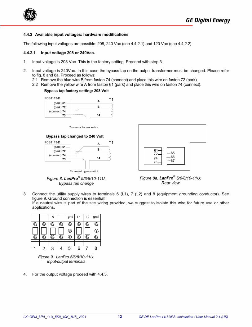
4.4.2.1 Input voltage 208 or 240Vac.
1. Input voltage is 208 Vac. This is the factory setting. Proceed with step 3.
2. Input voltage is 240Vac. In this case the bypass tap on the output transformer must be changed. Please referto fig. 8 and 8a. Proceed as follows:2.1 Remove the blue wire B from faston 74 (connect) and place this wire on faston 72 (park).2.2 Remove the yellow wire A from faston 61 (park) and place this wire on faston 74 (connect).
3. Connect the utility supply wires to terminals 6 (L1), 7 (L2) and 8 (equipment grounding conductor). Seefigure 9. Ground connection is essential!If a neutral wire is part of the site wiring provided, we suggest to isolate this wire for future use or otherapplications.
4. For the output voltage proceed with 4.4.3.
1 2 3 4 5 6 7 8
gndL2N gnd L1
Figure 9. LanPro 5/6/8/10-11U:Input/output terminals
Figure 8. LanPro® 5/6/8/10-11U:Bypass tap change
Figure 8a. LanPro® 5/6/8/10-11U:Rear view
T1A
To manual bypass switch
To manual bypass switch
Bypass tap factory setting: 208 Volt
Bypass tap changed to 240 Volt
61727473
656667
B
14
(park) 61(park) 72
(connect) 7473
(park) 61(park) 72
(connect) 7473
A
B
14
PCB1113-D
PCB1113-D T1
LX: OPM_LPA_11U_5K0_10K_1US_V021 13 GE DE LanPro-11U UPS: Installation / User Manual 2.1 (US)
GE Digital Energyg4.4.2.2 Input voltage 120Vac (optional, 5/6kVA only).
LanPro®-U UPS equipped with an (optional) step-up transformer (5/6kVA models only) can be connected to aninput voltage of 120Vac.
1. Connect the utility supply wires to terminals L, N and GND (equipment grounding conductor). See figure 10.Ground connection is essential!
2. For the output voltage proceed with 4.4.3.
4.4.3 Available output voltages: hardware modifications
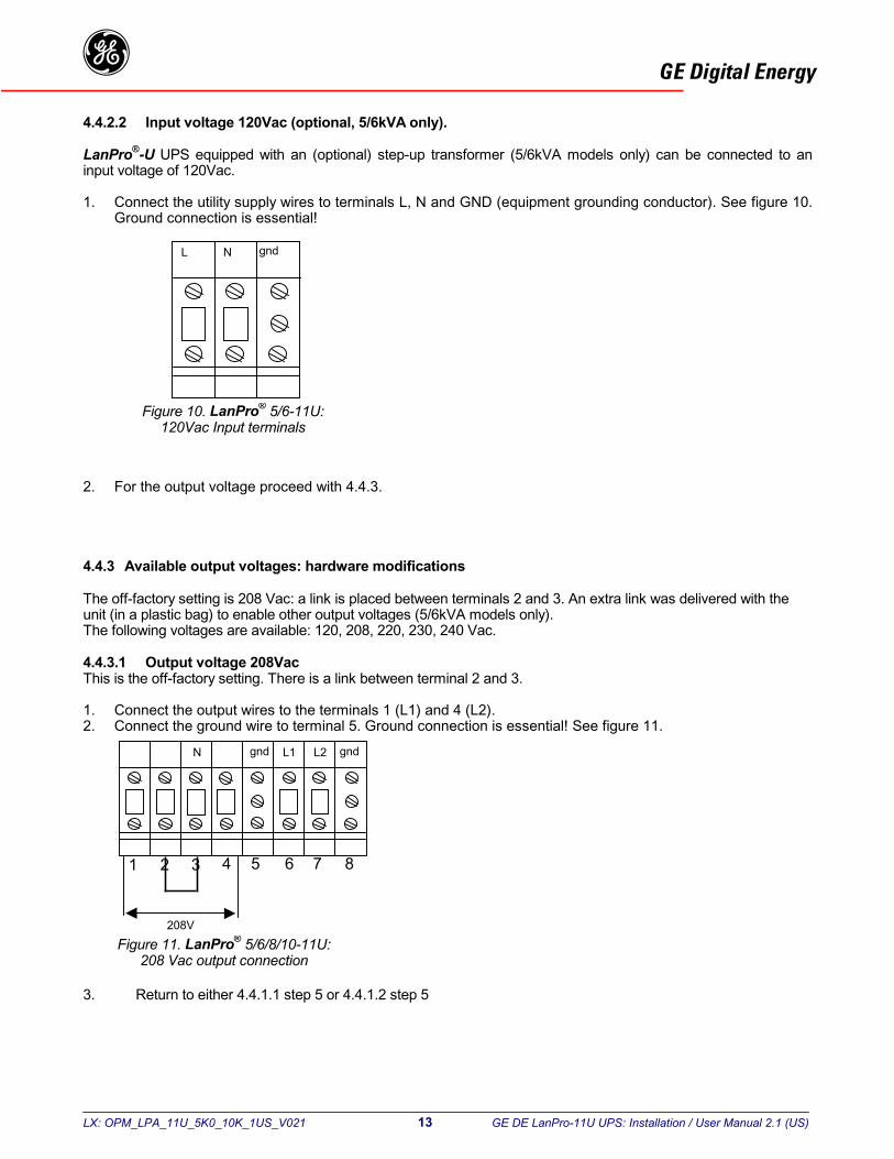
The off-factory setting is 208 Vac: a link is placed between terminals 2 and 3. An extra link was delivered with theunit (in a plastic bag) to enable other output voltages (5/6kVA models only).The following voltages are available: 120, 208, 220, 230, 240 Vac.
4.4.3.1 Output voltage 208VacThis is the off-factory setting. There is a link between terminal 2 and 3.
1. Connect the output wires to the terminals 1 (L1) and 4 (L2).2. Connect the ground wire to terminal 5. Ground connection is essential! See figure 11.
3. Return to either 4.4.1.1 step 5 or 4.4.1.2 step 5
gndNL
Figure 10. LanPro® 5/6-11U:120Vac Input terminals
1 2 3 4 5 6 7 8
gndL2N gnd L1
208V
Figure 11. LanPro® 5/6/8/10-11U:208 Vac output connection

LX: OPM_LPA_11U_5K0_10K_1US_V021 14 GE DE LanPro-11U UPS: Installation / User Manual 2.1 (US)
GE Digital Energyg4.4.3.2 Output voltage 120Vac split-phase
1. The factory setting of the output tap (208Vac) has to be changed to 240Vac. Please refer to fig. 12 and 12a.Proceed as follows:1.1 Remove the yellow wire L from faston 67 (connect) and place this wire on faston 65 (park).1.2 Remove the brown wire F from faston 66 (park) and place this wire on faston 67 (connect).
2. Connect the load wires between the terminals 1 (L1) and 2 (N) (120V), and between the terminals 3 (N) and 4(L2) (120V). Connect the ground wire to terminal 5. Ground connection is essential! Do not remove the linkbetween terminals 2 and 3. See figure 13.
3. Return to either 4.4.1.1 step 5 or 4.4.1.2 step 5
Figure 13. LanPro® 5/6/8/10-11U:120 Vac split-phase output connection
1 2 3 4 5 6 7 8
gndL2N gnd L1
120V 120V
Figure 12. LanPro 5/6/8/10-11U:Output tap change
Figure 12a. LanPro 5/6/8/10-11U:Rear view
61727473
656667
Output tap factory setting: 208 Volt
Output tap changed to 240 Volt
1113-DO
(park) 65(park) 66(connect) 67
FL
64
62
63
32V
88V
120V
PCB1113-CT1
O
(park) 65(park) 66(connect) 67
FL
64
62
63
32V
88V
120V
PCB1113-C
1113-D
T1
LX: OPM_LPA_11U_5K0_10K_1US_V021 15 GE DE LanPro-11U UPS: Installation / User Manual 2.1 (US)
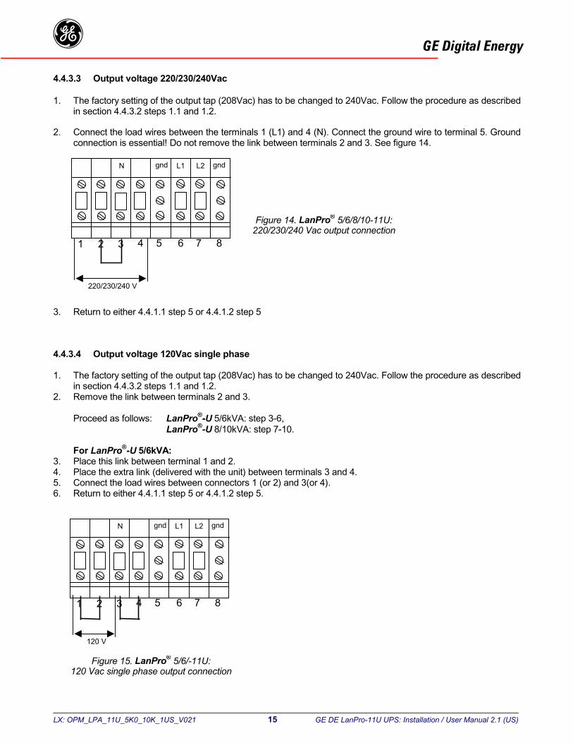
GE Digital Energyg4.4.3.3 Output voltage 220/230/240Vac
1. The factory setting of the output tap (208Vac) has to be changed to 240Vac. Follow the procedure as describedin section 4.4.3.2 steps 1.1 and 1.2.
2. Connect the load wires between the terminals 1 (L1) and 4 (N). Connect the ground wire to terminal 5. Groundconnection is essential! Do not remove the link between terminals 2 and 3. See figure 14.
3. Return to either 4.4.1.1 step 5 or 4.4.1.2 step 5
4.4.3.4 Output voltage 120Vac single phase
1. The factory setting of the output tap (208Vac) has to be changed to 240Vac. Follow the procedure as describedin section 4.4.3.2 steps 1.1 and 1.2.
2. Remove the link between terminals 2 and 3.
Proceed as follows: LanPro®-U 5/6kVA: step 3-6,LanPro®-U 8/10kVA: step 7-10.
For LanPro®-U 5/6kVA:3. Place this link between terminal 1 and 2.4. Place the extra link (delivered with the unit) between terminals 3 and 4.5. Connect the load wires between connectors 1 (or 2) and 3(or 4).6. Return to either 4.4.1.1 step 5 or 4.4.1.2 step 5.
Figure 14. LanPro® 5/6/8/10-11U:220/230/240 Vac output connection
1 2 3 4 5 6 7 8
gndL2N gnd L1
220/230/240 V
Figure 15. LanPro® 5/6/-11U:120 Vac single phase output connection
1 2 3 4 5 6 7 8
gndL2N gnd L1
120 V
LX: O
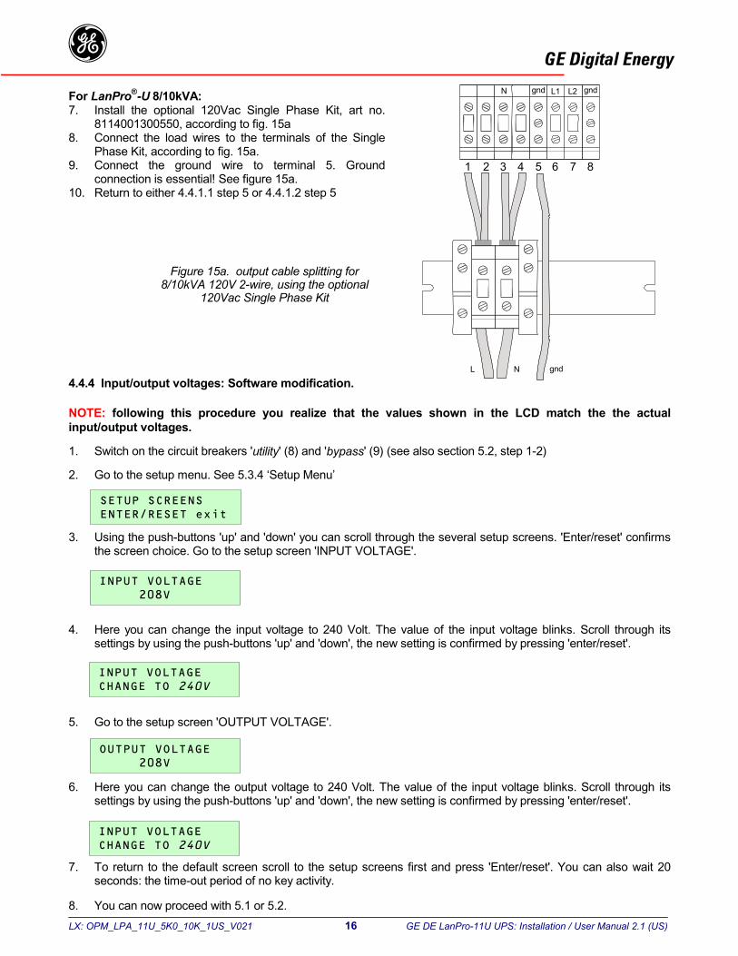
GE Digital EnergygFor LanPro®-U 8/10kVA:7. Install the optional 120Vac Single Phase Kit, art no.
8114001300550, according to fig. 15a8. Connect the load wires to the terminals of the Single
Phase Kit, according to fig. 15a.9. Connect the ground wire to terminal 5. Ground
connection is essential! See figure 15a.10. Return to either 4.4.1.1 step 5 or 4.4.1.2 step 5
4.4.4 Input/output voltages: Software modification.
NOTE: following this procedure you realize that the values shown in the LCD match the the actualinput/output voltages.
1. Switch on the circuit breakers 'utility' (8) and 'bypass' (9) (see also section 5.2, step 1-2)
2. Go to the setup menu. See 5.3.4 ‘Setup Menu’
3.
4.
5.
6.
7.
8.
Figure 15a. output cable splitting for8/10kVA 120V 2-wire, using the optional
120Vac Single Phase Kit
1 2 3 4 5 6 7 8
gnd gndL1 L2
gndL N
N
Using the push-buttons 'up' and 'down' you can scroll through the several setup screens. 'Enter/reset' confirmsthe screen choice. Go to the setup screen 'INPUT VOLTAGE'.
Here you can change the input voltage to 240 Volt. The value of the input voltage blinks. Scroll through itssettings by using the push-buttons 'up' and 'down', the new setting is confirmed by pressing 'enter/reset'.
Go to the setup screen 'OUTPUT VOLTAGE'.
Here you can change the output voltage to 240 Volt. The value of the input voltage blinks. Scroll through itssettings by using the push-buttons 'up' and 'down', the new setting is confirmed by pressing 'enter/reset'.
PM_LPA_11U_5K0_10K_1US_V021 16 GE DE LanPro-11U UPS: Installation / User Manual 2.1 (US)
To return to the default screen scroll to the setup screens first and press 'Enter/reset'. You can also wait 20seconds: the time-out period of no key activity.
You can now proceed with 5.1 or 5.2.
LX:
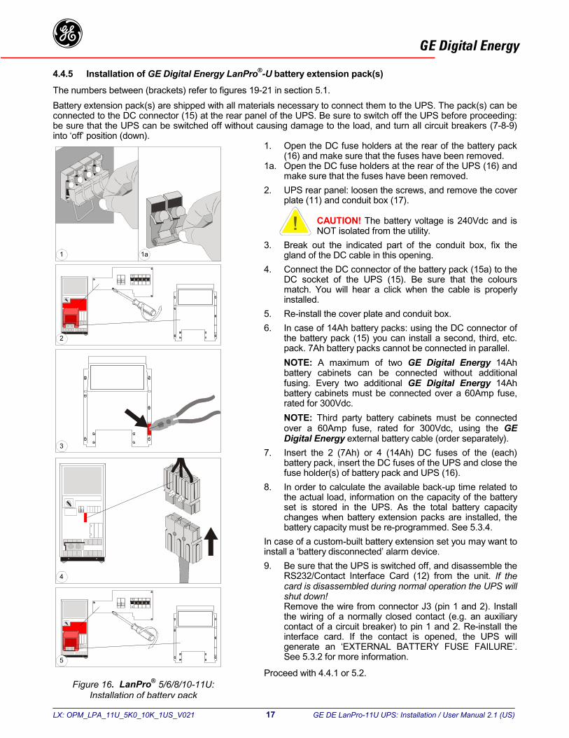
GE Digital Energyg4.4.5 Installation of GE Digital Energy LanPro®-U battery extension pack(s)The numbers between (brackets) refer to figures 19-21 in section 5.1.Battery extension pack(s) are shipped with all materials necessary to connect them to the UPS. The pack(s) can beconnected to the DC connector (15) at the rear panel of the UPS. Be sure to switch off the UPS before proceeding:be sure that the UPS can be switched off without causing damage to the load, and turn all circuit breakers (7-8-9)into ‘off’ position (down).
1. Open the DC fuse holders at the rear of the battery pack(16) and make sure that the fuses have been removed.
1a. Open the DC fuse holders at the rear of the UPS (16) andmake sure that the fuses have been removed.
2. UPS rear panel: loosen the screws, and remove the coverplate (11) and conduit box (17).
CAUTION! The battery voltage is 240Vdc and isNOT isolated from the utility.
3. Break out the indicated part of the conduit box, fix thegland of the DC cable in this opening.
4. Connect the DC connector of the battery pack (15a) to theDC socket of the UPS (15). Be sure that the coloursmatch. You will hear a click when the cable is properlyinstalled.
5. Re-install the cover plate and conduit box.6. In case of 14Ah battery packs: using the DC connector of
the battery pack (15) you can install a second, third, etc.pack. 7Ah battery packs cannot be connected in parallel.NOTE: A maximum of two GE Digital Energy 14Ahbattery cabinets can be connected without additionalfusing. Every two additional GE Digital Energy 14Ahbattery cabinets must be connected over a 60Amp fuse,rated for 300Vdc.NOTE: Third party battery cabinets must be connectedover a 60Amp fuse, rated for 300Vdc, using the GEDigital Energy external battery cable (order separately).
7. Insert the 2 (7Ah) or 4 (14Ah) DC fuses of the (each)battery pack, insert the DC fuses of the UPS and close thefuse holder(s) of battery pack and UPS (16).
8. In order to calculate the available back-up time related tothe actual load, information on the capacity of the batteryset is stored in the UPS. As the total battery capacitychanges when battery extension packs are installed, thebattery capacity must be re-programmed. See 5.3.4.
In case of a custom-built battery extension set you may want toinstall a ‘battery disconnected’ alarm device.9. Be sure that the UPS is switched off, and disassemble the
RS232/Contact Interface Card (12) from the unit. If thecard is disassembled during normal operation the UPS willshut down!Remove the wire from connector J3 (pin 1 and 2). Installthe wiring of a normally closed contact (e.g. an auxiliarycontact of a circuit breaker) to pin 1 and 2. Re-install theinterface card. If the contact is opened, the UPS willgenerate an ‘EXTERNAL BATTERY FUSE FAILURE’.See 5.3.2 for more information.
Proceed with 4.4.1 or 5.2.
1 1a
2
3
4
5
Figure 16. LanPro® 5/6/8/10-11U:Installation of battery pack
OPM_LPA_11U_5K0_10K_1US_V021 17 GE DE LanPro-11U UPS: Installation / User Manual 2.1 (US)
LX: OPM_LPA_11U_5K0_10K_1US_V021 18 GE DE LanPro-11U UPS: Installation / User Manual 2.1 (US)
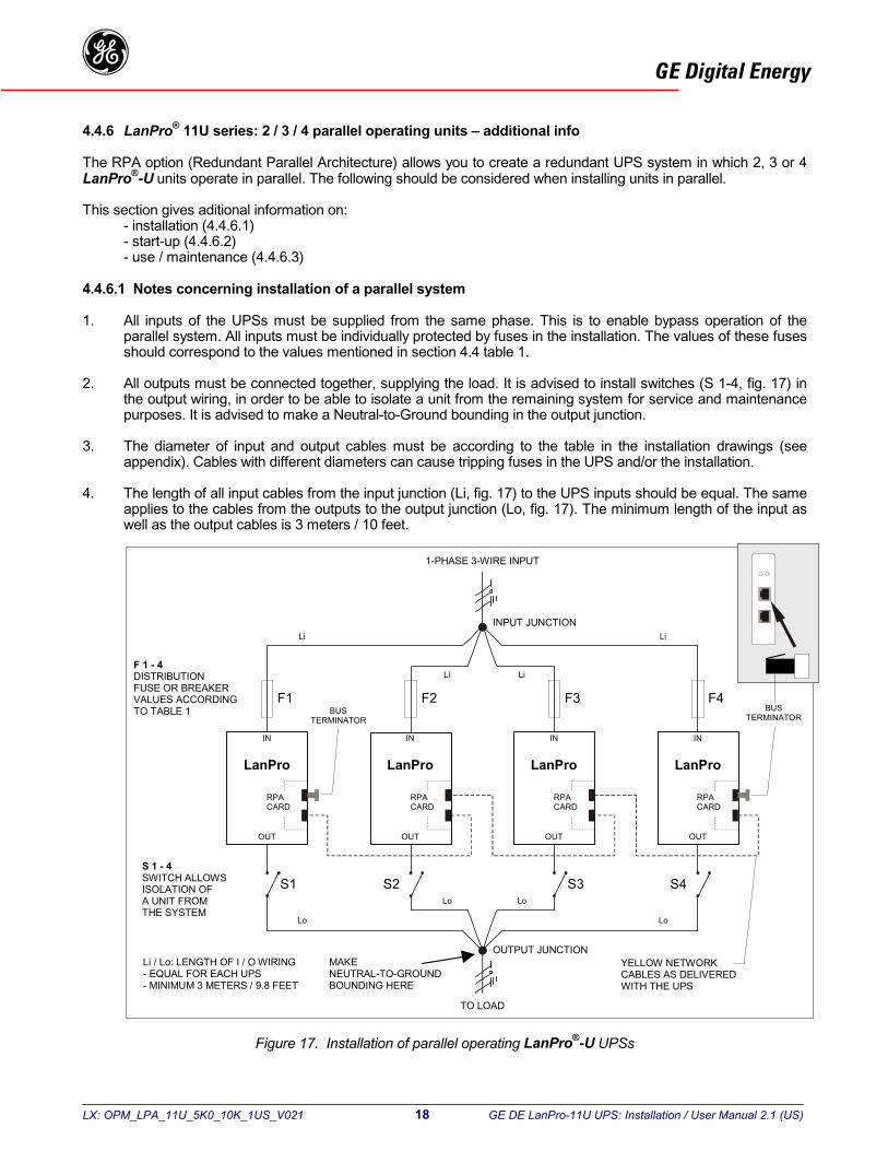
GE Digital Energyg4.4.6 LanPro® 11U series: 2 / 3 / 4 parallel operating units – additional info
The RPA option (Redundant Parallel Architecture) allows you to create a redundant UPS system in which 2, 3 or 4LanPro®-U units operate in parallel. The following should be considered when installing units in parallel.
This section gives aditional information on:- installation (4.4.6.1)- start-up (4.4.6.2)- use / maintenance (4.4.6.3)
4.4.6.1 Notes concerning installation of a parallel system
1. All inputs of the UPSs must be supplied from the same phase. This is to enable bypass operation of theparallel system. All inputs must be individually protected by fuses in the installation. The values of these fusesshould correspond to the values mentioned in section 4.4 table 1.
2. All outputs must be connected together, supplying the load. It is advised to install switches (S 1-4, fig. 17) inthe output wiring, in order to be able to isolate a unit from the remaining system for service and maintenancepurposes. It is advised to make a Neutral-to-Ground bounding in the output junction.
3. The diameter of input and output cables must be according to the table in the installation drawings (seeappendix). Cables with different diameters can cause tripping fuses in the UPS and/or the installation.
4. The length of all input cables from the input junction (Li, fig. 17) to the UPS inputs should be equal. The sameapplies to the cables from the outputs to the output junction (Lo, fig. 17). The minimum length of the input aswell as the output cables is 3 meters / 10 feet.
Figure 17. Installation of parallel operating LanPro®-U UPSs
F1 F2 F3 F4
LanPro
IN
OUT
INPUT JUNCTION
OUTPUT JUNCTION
TO LOAD
1-PHASE 3-WIRE INPUT
Li Li
LiLi
Lo Lo
LoLo
YELLOW NETWORKCABLES AS DELIVEREDWITH THE UPS
Li / Lo: LENGTH OF I / O WIRING- EQUAL FOR EACH UPS- MINIMUM 3 METERS / 9.8 FEET
S 1 - 4SWITCH ALLOWSISOLATION OFA UNIT FROMTHE SYSTEM
F 1 - 4DISTRIBUTIONFUSE OR BREAKERVALUES ACCORDINGTO TABLE 1
LanPro
IN
OUT
LanPro
IN
OUT
LanPro
IN
OUT
RPACARD
BUSTERMINATOR
S1 S2 S3 S4
BUSTERMINATOR
RPACARD
RPACARD
RPACARD
MAKENEUTRAL-TO-GROUNDBOUNDING HERE
LX: OPM_LPA_11U_5K0_10K_1US_V021
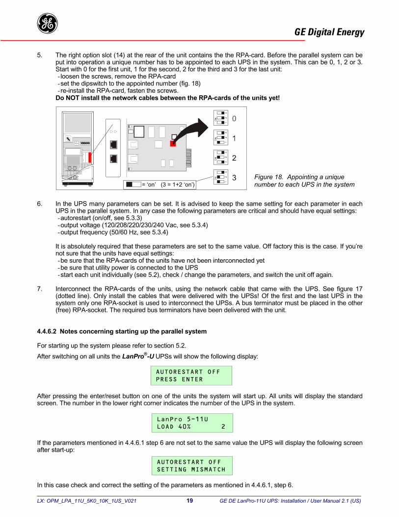
GE Digital Energyg5. The right option slot (14) at the rear of the unit contains the the RPA-card. Before the parallel system can be
put into operation a unique number has to be appointed to each UPS in the system. This can be 0, 1, 2 or 3.Start with 0 for the first unit, 1 for the second, 2 for the third and 3 for the last unit:- loosen the screws, remove the RPA-card- set the dipswitch to the appointed number (fig. 18)- re-install the RPA-card, fasten the screws.
Do NOT install the network cables between the RPA-cards of the units yet!
6. In the UPS many parameters can be set. It is advised to keep the same setting for each parameter in eachUPS in the parallel system. In any case the following parameters are critical and should have equal settings:- autorestart (on/off, see 5.3.3)- output voltage (120/208/220/230/240 Vac, see 5.3.4)- output frequency (50/60 Hz, see 5.3.4)
It is absolutely required that these parameters are set to the same value. Off factory this is the case. If you’renot sure that the units have equal settings:- be sure that the RPA-cards of the units have not been interconnected yet- be sure that utility power is connected to the UPS- start each unit individually (see 5.2), check / change the parameters, and switch the unit off again.
7. Interconnect the RPA-cards of the units, using the network cable that came with the UPS. See figure 17(dotted line). Only install the cables that were delivered with the UPSs! Of the first and the last UPS in thesystem only one RPA-socket is used to interconnect the UPSs. A bus terminator must be placed in the other(free) RPA-socket. The required bus terminators have been delivered with the unit.
4.4.6.2 Notes concerning starting up the parallel system
For starting up the system please refer to section 5.2.After switching on all units the LanPro®-U UPSs will show the following display:
After pressing the enter/reset button on one of the units the system will start up. All units will display the standardscreen. The number in the lower right corner indicates the number of the UPS in the system.
If the parameters mentioned in 4.4.6.1 step 6 are not set to the same value the UPS will display the following screenafter start-up:
In this case check and correct the setting
Figure 18. Appointing a uniquenumber to each UPS in the system= ‘on’ (3 = 1+2 ‘on’)
19 GE DE LanPro-11U UPS: Installation / User Manual 2.1 (US)
of the parameters as mentioned in 4.4.6.1, step 6.
LX: OPM_LPA_11U_5K0_10K_1US_V021 20 GE DE LanPro-11U UPS: Installation / User Manual 2.1 (US)
GE Digital Energyg4.4.6.3 Notes concerning use / maintenance of a parallel system
ECO-mode:
If LanPro®-U units operate in parallel, the ECO-mode feature is not available.
No-load shutdown:
If LanPro®-U units operate in parallel, the no-load shutdown function is not available.
Manual bypass:
If you want to switch one of the UPSs to bypass operation using the manual bypass switch (switch isturned into position 2) then all UPSs in the parallel system have to be switched to bypass operation inorder to prevent damage.
Maintenance:
To isolate a unit from the redundant system:1. Switch off the UPS which has to be isolated,2. Remove the installation fuse from the input of that UPS (F1-4 in figure 17),3. Separate the output of the UPS from the output junction (S1-4 in figure 17).
To re-enter the unit into the system:1. Reinstall the installation input fuse,2. Connect the output of the UPS to the output junction,3. Switch on the UPS.

LX: OPM_LPA_11U_5K0_10K_1US_V021 21 GE DE LanPro-11U UPS: Installation / User Manual 2.1 (US)
GE Digital Energyg
5.1 Description of Front and Rear Panel
1 LCD screen2x16 characters, shows UPS system data, status messages, settings.The language is selectable: English, German, French, Italian,Spanish. Section 5.3.4 describes the selection procedure.
2-4 Push-buttonsWith the button keypads ‘down’ (2) and ‘up’ (4) you can scroll throughthe several screens, with keypad 'reset/enter' (3) a selection isconfirmed. Keypad activity is accompanied by a short beep. If there isno keypad activity during 20 seconds the LCD screen will return to thedefault screen (except for the service screens, see section 5.3.3).
5 LED 'operation' indicates normal operation.6 LED ‘alarm’, indicates an alarm situation, accompanied by alarm
message(s) on the display and a sounding buzzer.See section 5.3.2 for more information.
7 Switch ‘UPS on/off’, turns on/off the complete UPS, including theautomatic bypass!
8 Circuit breaker ‘Utility on/off’, protection fuse for utility input andbattery charger.
9 Circuit breaker ‘Bypass on/off’, fuse to protect the system in case ofsevere overload or short circuit in the UPS load.
10 Manual Bypass Switch: 1 = Load on UPS2 = Load on utility
WARNING: In position 2, if the input line is energized, theoutput is also live regardless the position of the circuitbreakers ‘utility’ and ‘bypass’.
11 Cover plate, behind it:11a Output terminals11b Input terminals12 RS232/Contact Interface Card, with:
12a - RS232 Interface Port (see section 6.1)- Emergency shutdown (see 4.4.1 and 6.2)- Battery disconnected, pin 1-2 (can be used for external
signaling).13 Free option slot for plug-in cards:
- Relay Card (see 6.3)- SNMP Card (see 6.4)
14 Option slot for RPA (Redundant Parallel Architecture) Card. Notavailable yet.
15 DC socket / connector.16 Battery fuse holder17 Conduit box18 Cable inlet
Figure 19 :Front and rear panel
6 5 1 2 4 3
16 7 8 9
10
11a
11b
17
15
1418
1312
12a11
����������������
5 - Operation
LX: OPM_LPA_11U_5K0_10K_1US_V021 22 GE DE LanPro-11U UPS: Installation / User Manual 2.1 (US)
GE Digital Energyg
Rear panel of the step-up transformer:
11b Input terminals L, N and GND
17 Conduit box
18 Cable inlet
Rear panel of (optional) battery extension pack:
15 DC socket (14Ah only)15a DC connector
16 Battery fuse holder(s)7Ah: 2 fuses14Ah: 4 fuses
19 Gland to fasten cable in conduit box of UPS
17
1811b
15a
1615
14Ah
19
Figure 21. Rear panel batteryextension pack (optional)
Figure 20. Rear panel of thestep-up transformer
LX: OPM
GE Digital Energyg5.2 Start-up
The numbers between (brackets) refer to figure 19 in section 5.1.
Note: the UPS can be started on battery power if the utility input voltage is not available or if circuit breaker‘utility’ is in off-position: simply skip step 1. To prevent accidental discharging of the batteries, it is howeverrecommended to proceed with step 1 and start the unit only when the utility input voltage is available.
1. Turn breaker 'utility' (8) and breaker 'bypass' (9), both on the rear panel, into position ‘on’ (up).
2. Some UPS parameters (e.g. voltage, frequency, LCD language) are user selectable. If you want to changeone or more settings, please refer to section 5.3.4 ‘Setup Menu’ now. Changing the settings later is possible,however only after switching off the unit.
3. Turn switch 'UPS on/off' (rear panel, 7) into position ‘on’ (up).The green LED 'operation' (front panel, 5) will illuminate.
After switching on the UPS performs a self-test and the display (front panel, 1) will show:
Ad
Iby
4. Tmrc
5. Iu
fter completion of the self-test the output voltage of the UPS is available and the unit is ready for use. Theisplay will show the default screen: model and actual load (values are examples)
_LPA_11U_5K0_10K_1US_V021 23 GE DE LanPro-11U UPS: Installation / User Manual 2.1 (US)
n case of a system failure the self-test results in a failure message; this message is displayed for 30 secondsefore the self-test is repeated automatically. If the faulty situation persists, switch off the UPS and contactour dealer. See chapter 9 for more information.
hough the batteries (the internal energy reserve) were fully charged when the UPS left the factory, theyight have lost some energy during transport and/or storage. It is recommended to allow the UPS to
echarge the batteries for a few hours. This way you ensure that the UPS can provide sufficient runtime inase of a utility power failure.
f not yet switched on, the equipment connected to the LanPro®-U UPS can be switched on now; operate assual.

L
GE Digital Energyg5.3 Use
Once the unit is in operation, there is no need to switch the unit on/off during use.If the manual bypass switch (rear panel, 10) is in position '1', switching off by the on/off switch (rear panel, 7) resultsin a total absence of the output voltage (also the bypass voltage) of at least 5 secs.
If an emergency shutdown switch has been installed (see 4.4.1.1-2, step 6) the UPS will stop immediately when theswitch is opened. Restart is only possible after closing the switch and turning the UPS off and on again with theUPS on/off switch (rear panel, 7).
The UPS is operated via the push-buttons (front panel, 2-3-4) and the LCD display (front panel, 1). Furthermore theUPS can be controlled via the RS232/contact interface port (rear panel, 12a). For more information see 6.1.
The menus on the display can be divided into 5 groups:1 standard screen2 information menu (5.3.1)3 status- and alarm menu (5.3.2)4 service menu (5.3.3)5 set-up menu (5.3.4)
The standard menu shows UPS model and actual load.
5
WpAT
.3.1 Information Menu
hen the default screen is displayed the first information screen can be entered by depressing the 'up' key (frontanel, 4). Using the 'up' and 'down' keys (front panel, 4 and 2) you can scroll through several information screens.fter the last information screen the default screen will appear.he screens display the following information:
Utility voltage and utility frequency, and the power delivered by the utility.
Output voltages and output frequency, and the power delivered by the UPS (as %of the nominal UPS rating).
The temperature near the batteries, the battery voltage and the battery current(charging: + value, discharging: - value).
°The remaining battery runtime (or autonomy) during a utility failure.
The total operating time of the UPS.
X: OPM_LPA_11U_5K0_10K_1US_V021 24 GE DE LanPro-11U UPS: Installation / User Manual 2.1 (US)
L
GE Digital Energyg5.3.2 Status and Alarm Menu
The UPS alerts the user with a standard alarm screen that the operating mode has changed and/or that an alarmsituation occurs:
The actual operating mode, the possible modes are mentioned below. The lowerline -if displayed- shows that an alarm occurred. More information can be retrievedwith the 'up' key. If no further information is available, the second line is blank.
P
Dtm
ossible operating modes:The normal operating mode. For more information see section 3.2.Overload or failure situation. For more information see section 3.5.For a detailed description of this mode see section 3.3.No power is delivered to the load. This can be the result of a command via the RS232Port, or because no electric energy is available (utility failure, depleted batteries).Service mode. For more information see section 3.6.ECO-Mode. See section 5.5.5
epressing the 'up’ key from the standard alarm screen shows, in priority order, which alarms are active,. Scrollhrough the screens with the 'up' and 'down' keys. Alarm message texts can succeed each other. The following
essages are possible:
The output capacitor C2 is defective. Contact your dealer.
The load exceeds the rated output power of the UPS, and the output voltage canno longer be guaranteed. This text alternates with the following screen:
showing the actual load as % of the nominal UPS rating. These messages aredisplayed if the load is > 100%.If the load exceeds 150% the UPS will immediately switch to bypass, assuming
that the conditions for a transfer to bypass are fulfilled. If an overload conditionbetween 100-150% persists, the UPS can eventually also switch to bypassoperation due to temperature protection. If a transfer to bypass is inhibited (due tovoltage or frequency errors of the utility supply) the UPS may automatically switchoff within a few seconds (load dependent). Output power is lost at that moment. Toavoid these problems, be absolutely certain that the power demands of theprotected equipment are within the limits of the UPS.The temperature of the heatsinks or output transformer is too high. As a result theoutput voltage may be transferred to bypass.
The operating temperature can rise to intolerable levels as a result of:• extreme environmental temperature• lack of proper ventilation• an overload situation• fan failureIf the UPS operates in 'on line' mode, it will switch to bypass until the temperature isnormal again. If however the UPS operates 'on battery', a shutdown will occur andoutput power is lost.
The internal DC voltage is too high, internal failure
The output voltage of the battery charger is too high, internal failure
The battery temperature is too high due to a battery failure or a too high ambienttemperature
X: OPM_LPA_11U_5K0_10K_1US_V021 25 GE DE LanPro-11U UPS: Installation / User Manual 2.1 (US)
L
GE Digital EnergygAfter 24 hours of charging time, the battery voltage did not reach the normal floatvoltage. This may be caused by faulty batteries, too many battery packs connectedor a charger fault.
The main DC-capacitor needs replacement due to aging or failure
Due to a failure the output converter's output is not available. As a result the loadmay have been transferred to bypass.
The remaining runtime is zero. As a result the load may have been transferred tobypass.
The remaining run time is less than the set time (standard 2 minutes). This textalternates with the following screen:
The output voltage can be lost after the indicated time due to discharged battery.Controlled shutdown of any computer equipment is absolutely necessary at thispoint. (Using the RS232 or SNMP communications interface, this procedure can be
initiated automatically on unattended systems). If the UPS operates at 100% load,the shutdown procedure should be completed within 2 minutes after the 'batterylow' alarm started. When the batteries are fully discharged, the UPS is no longerable to power the connected equipment.The static bypass circuit breaker (rear panel, 9) is in 'off' (down position): no bypassvoltage available. Utility voltage is available. If not manually operated, this mayhave been caused by an overload situation.
The utility circuit breaker (rear panel, 8) is in the 'off' (down position): no line voltageavailable, bypass voltage is available. If not manually operated, this may have beencaused by an internal system failure.
The internal battery fuse is defective; this may have been caused by an internalsystem failure. This alarm also appears if no batteries are installed.
The (custom-built) battery extension set has been disconnected from the system:its energy reserve is not available. See 4.4.2 step 12 for details.
The batteries are (almost) chemically worn out. If the batteries are aged, they must
be replaced as soon as possible to ensure full protection for your equipment (seesection 8.3).The utility voltage or utility frequency are outside UPS input tolerance (see chapter10, specifications)
The utility voltage or utility frequency are outside bypass input tolerance but insideUPS (rectifier) input tolerance (see chapter 10, specifications). Bypass operation isinhibited: if for whatever reason the output converter is unable to deliver the
X: OPM_LPA_11U_5K0_10K_1US_V021 26 GE DE LanPro-11U UPS: Installation / User Manual 2.1 (US)
required output, output power is lost.
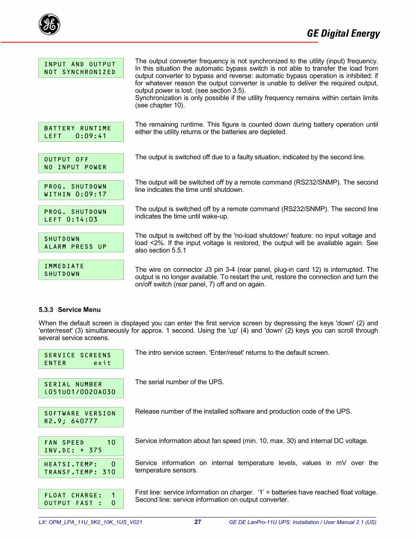
L
GE Digital EnergygThe output converter frequency is not synchronized to the utility (input) frequency.In this situation the automatic bypass switch is not able to transfer the load fromoutput converter to bypass and reverse: automatic bypass operation is inhibited: if
5
W's
for whatever reason the output converter is unable to deliver the required output,output power is lost. (see section 3.5).Synchronization is only possible if the utility frequency remains within certain limits(see chapter 10).
The remaining runtime. This figure is counted down during battery operation untileither the utility returns or the batteries are depleted.
The output is switched off due to a faulty situation, indicated by the second line.
The output will be switched off by a remote command (RS232/SNMP). The secondline indicates the time until shutdown.
The output is switched off by a remote command (RS232/SNMP). The second lineindicates the time until wake-up.
The output is switched off by the 'no-load shutdown' feature: no input voltage and load <2%. If the input voltage is restored, the output will be available again. Seealso section 5.5.1
The wire on connector J3 pin 3-4 (rear panel, plug-in card 12) is interrupted. Theoutput is no longer available. To restart the unit, restore the connection and turn the
on/off switch (rear panel, 7) off and on again..3.3 Service Menu
hen the default screen is displayed you can enter the first service screen by depressing the keys 'down' (2) andenter/reset' (3) simultaneously for approx. 1 second. Using the 'up' (4) and 'down' (2) keys you can scroll througheveral service screens.
The intro service screen. 'Enter/reset' returns to the default screen.
The serial number of the UPS.
Release number of the installed software and production code of the UPS.
Service information about fan speed (min. 10, max. 30) and internal DC voltage.
Service information on internal temperature levels, values in mV over thetemperature sensors.
First line: service information on charger. ‘1’ = batteries have reached float voltage.Second line: service information on output converter.
X: OPM_LPA_11U_5K0_10K_1US_V021 27 GE DE LanPro-11U UPS: Installation / User Manual 2.1 (US)
L
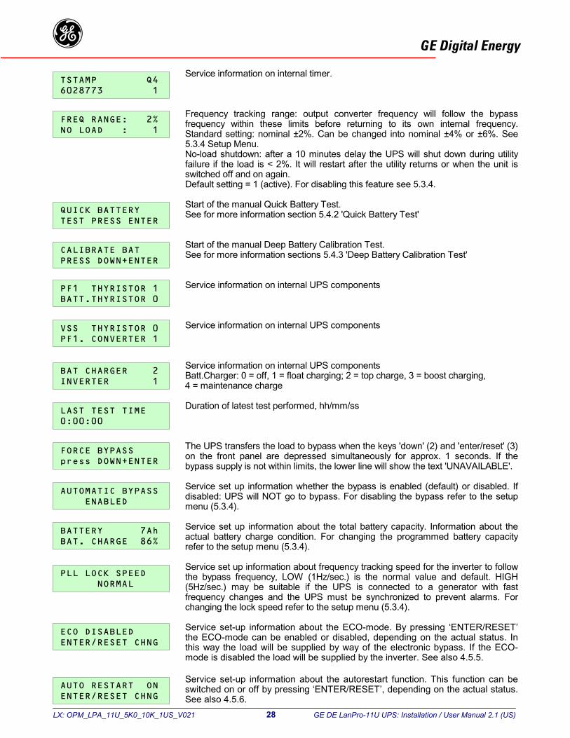
GE Digital EnergygService information on internal timer.
Frequency tracking range: output converter frequency will follow the bypassfrequency within these limits before returning to its own internal frequency.Standard setting: nominal ±2%. Can be changed into nominal ±4% or ±6%. See
5.3.4 Setup Menu.No-load shutdown: after a 10 minutes delay the UPS will shut down during utilityfailure if the load is < 2%. It will restart after the utility returns or when the unit isswitched off and on again.Default setting = 1 (active). For disabling this feature see 5.3.4.Start of the manual Quick Battery Test.See for more information section 5.4.2 'Quick Battery Test'
Start of the manual Deep Battery Calibration Test.See for more information sections 5.4.3 'Deep Battery Calibration Test'
Service information on internal UPS components
Service information on internal UPS components
Service information on internal UPS componentsBatt.Charger: 0 = off, 1 = float charging; 2 = top charge, 3 = boost charging,4 = maintenance charge
Duration of latest test performed, hh/mm/ss
The UPS transfers the load to bypass when the keys 'down' (2) and 'enter/reset' (3)on the front panel are depressed simultaneously for approx. 1 seconds. If thebypass supply is not within limits, the lower line will show the text 'UNAVAILABLE'.
Service set up information whether the bypass is enabled (default) or disabled. Ifdisabled: UPS will NOT go to bypass. For disabling the bypass refer to the setupmenu (5.3.4).
Service set up information about the total battery capacity. Information about theactual battery charge condition. For changing the programmed battery capacityrefer to the setup menu (5.3.4).
Service set up information about frequency tracking speed for the inverter to followthe bypass frequency, LOW (1Hz/sec.) is the normal value and default. HIGH(5Hz/sec.) may be suitable if the UPS is connected to a generator with fast
frequency changes and the UPS must be synchronized to prevent alarms. Forchanging the lock speed refer to the setup menu (5.3.4).Service set-up information about the ECO-mode. By pressing ‘ENTER/RESET’the ECO-mode can be enabled or disabled, depending on the actual status. Inthis way the load will be supplied by way of the electronic bypass. If the ECO-
mode is disabled the load will be supplied by the inverter. See also 4.5.5.Service set-up information about the autorestart function. This function can beswitched on or off by pressing ‘ENTER/RESET’, depending on the actual status.See also 4.5.6.
X: OPM_LPA_11U_5K0_10K_1US_V021 28 GE DE LanPro-11U UPS: Installation / User Manual 2.1 (US)
L
GE Digital Energyg5.3.4 Setup Menu
To enter the setup menu:1. Be sure the UPS is switched off.2. Press push-button 'enter/reset' (front panel) and then turn switch ‘UPS on/off’ (rear panel) into position ‘on’ (up).
Keep enter/reset pressed until setup menu appears.Using push-buttons 'up' and 'down' you can scroll through the several setup screens, 'enter/reset' confirms a screenchoice. After selecting a setup screen you can scroll through its settings using the push-buttons 'up' and 'down', asetting is confirmed by pressing 'enter/reset'. To abort the setup procedure (i.e. without changing the setting) justwait the 20 seconds time-out period after which the default screen will return.
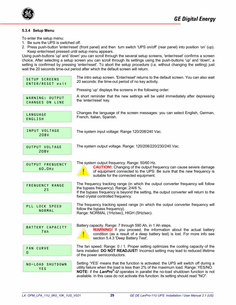
The intro setup screen. 'Enter/reset' returns to the default screen. You can also wait20 seconds: the time-out period of no key activity.
Pressing ‘up’ displays the screens in the following order:A short reminder that the new settings will be valid immediately after depressingthe ‘enter/reset’ key.
Changes the language of the screen messages: you can select English, German,French, Italian, Spanish.
The system input voltage: Range 120/208/240 Vac.
The system output voltage. Range: 120/208/220/230/240 Vac.
The system output frequency. Range: 50/60 Hz.CAUTION!: Changing of the output frequency can cause severe damageof equipment connected to the UPS: Be sure that the new frequency issuitable for the connected equipment.
The frequency tracking range (in which the output converter frequency will followthe bypass frequency). Range: 2/4/6 %.If the bypass frequency is beyond the setting, the output converter will return to the
fixed crystal controlled frequency.The frequency tracking speed range (in which the output converter frequency willfollow the bypass frequency).Range: NORMAL (1Hz/sec), HIGH (5Hz/sec).
Battery capacity. Range: 7 through 590 Ah, in 1 Ah steps.WARNING! If you proceed, the information about the actual batterycondition (as a result of a deep battery test) is lost. For more info seesection 5.4.3 'Deep Battery Test'.
The fan speed. Range: 0 / 1. Proper setting optimizes the cooling capacity of thefans installed. DO NOT READJUST! Incorrect setting may lead to reduced lifetime
of the power semiconductors.Setting ‘YES’ means that the function is activated: the UPS will switch off during autility failure when the load is less than 2% of the maximum load. Range: YES/NO.NOTE: if the LanPro®-U operates in parallel the no-load shutdown function is not
X: OPM_LPA_11U_5K0_10K_1US_V021 29 GE DE LanPro-11U UPS: Installation / User Manual 2.1 (US)
available. In this case do not activate this function: its setting should read "NO".
L
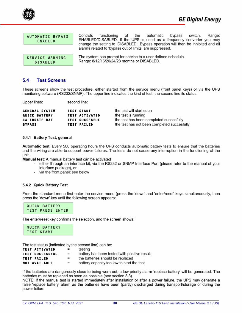
GE Digital EnergygControls functioning of the automatic bypass switch. Range:ENABLED/DISABLED. If the UPS is used as a frequency converter you maychange the setting to ‘DISABLED’. Bypass operation will then be inhibited and allalarms related to ‘bypass out of limits’ are suppressed.
The system can prompt for service to a user defined schedule.Range: 8/12/16/20/24/28 months or DISABLED.
5.4 Test Screens
These screens show the test procedure, either started from the service menu (front panel keys) or via the UPSmonitoring software (RS232/SNMP). The upper line indicates the kind of test, the second line its status.
Upper lines: second line:
the test will start soonthe test is runningthe test has been completed succesfullythe test has not been completed succesfully
5.4.1 Battery Test, general
Automatic test: Every 500 operating hours the UPS conducts automatic battery tests to ensure that the batteriesand the wiring are able to support power failures. The tests do not cause any interruption in the functioning of theunit.Manual test: A manual battery test can be activated
- either through an interface kit, via the RS232 or SNMP Interface Port (please refer to the manual of yourinterface package), or
- via the front panel: see below
5.4.2 Quick Battery Test
From the standard menu first enter the service menu (press the 'down' and 'enter/reset' keys simultaneously, thenpress the 'down' key until the following screen appears:
T
T
IfbNfap
he enter/reset key confirms the selection, and the screen shows:
X: OPM_LPA_11U_5K0_10K_1US_V021 30 GE DE LanPro-11U UPS: Installation / User Manual 2.1 (US)
he test status (indicated by the second line) can be:= testing= battery has been tested with positive result= the batteries should be replaced= battery capacity too low to start the test
the batteries are dangerously close to being worn out, a low priority alarm 'replace battery' will be generated. Theatteries must be replaced as soon as possible (see section 8.3).OTE: If the manual test is started immediately after installation or after a power failure, the UPS may generate alse 'replace battery' alarm as the batteries have been (partly) discharged during transport/storage or during theower failure.
L
GE Digital Energyg5.4.3 Deep Battery Test
The runtime as shown on the LCD screen is calculated, and the value is initially based on the capacity of newbatteries. As batteries age, their capacity deteriorates, and as a result the initial battery capacity may be toounreliable for a proper runtime prediction. The UPS is able to keep track of the aging process, if a 'deep battery test'(battery calibration test) is executed regularly. During such a test the condition of the batteries is tested, and theresult of the test is stored, and used by the UPS system for future runtime calculations.
We advise performing a deep battery test on a regular basis. For accuracy reasons the interval should depend onthe number of discharges . With one discharge per month a 6 month interval is sufficient. If the discharge interval isshorter than once a week a monthly deep battery test is advised.
A deep battery test can be started only if the following conditions are met:- The load should be more than 30% of nominal load- The batteries should be fully charged (100% on screen)- There are no alarms at the time the test is started.
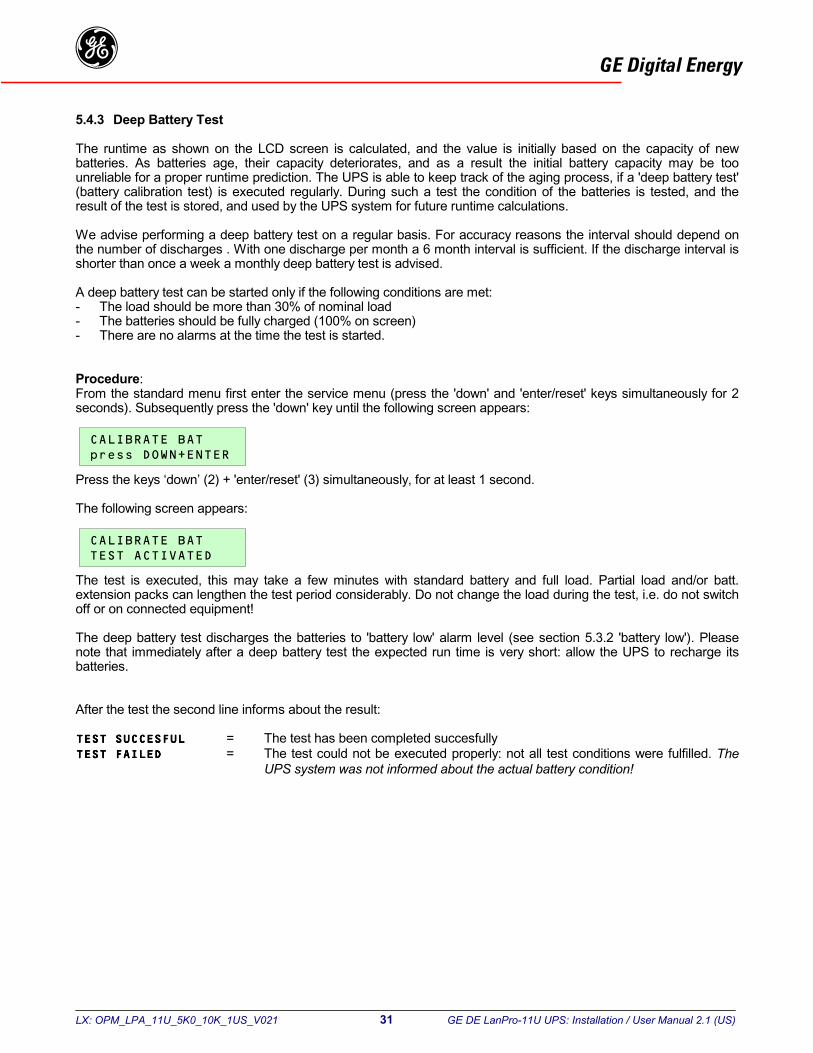
Procedure:From the standard menu first enter the service menu (press the 'down' and 'enter/reset' keys simultaneously for 2seconds). Subsequently press the 'down' key until the following screen appears:
P
T
Teo
Tnb
A
ress the keys ‘down’ (2) + 'enter/reset' (3) simultaneously, for at least 1 second.
he following screen appears:
X: OPM_LPA_11U_5K0_10K_1US_V021 31 GE DE LanPro-11U UPS: Installation / User Manual 2.1 (US)
he test is executed, this may take a few minutes with standard battery and full load. Partial load and/or batt.xtension packs can lengthen the test period considerably. Do not change the load during the test, i.e. do not switchff or on connected equipment!
he deep battery test discharges the batteries to 'battery low' alarm level (see section 5.3.2 'battery low'). Pleaseote that immediately after a deep battery test the expected run time is very short: allow the UPS to recharge itsatteries.
fter the test the second line informs about the result:
= The test has been completed succesfully= The test could not be executed properly: not all test conditions were fulfilled. The
UPS system was not informed about the actual battery condition!
L
GE Digital Energyg5.5 Other Features
5.5.1 Shutdown
'Remote shutdown': Using communication capabilities, the computer can direct the UPS to turn itself off followingcontrolled shutdown of the system. Subsequently the UPS will remain off for at least a few seconds (see also 6.1).LED 'operation' will blink green. The unit will start up again as soon as the utility returns.
'No-load shutdown': The UPS will also switch off if the load is < 2% of the maximum load, and the input is absent formore than 10 minutes. For more information see section 5.3.2, message 'SHUTDOWN ALARM'.NOTE: If the LanPro®-U UPS operates in parallel, the no-load function is not available.
'Emergency shutdown': for more information see section 5.3.2, message 'IMMEDIATE SHUTDOWN'.
5.5.2 Mains start
The UPS is able to start, even if the batteries are not connected. Alarm messages 'BATTERY FUSE FAILURE' and'BATTERY DEPLETED' will be shown. The run time is zero.
5.5.3 Sleep and wake-up
GE Digital Energy UPS monitoring software allows you to program a 'sleep period' of the UPS by sending twocommands to the UPS:
- shut down after # minutes, and subsequently:- shut down during # hours.
After the first command the following screen appears:
During the sleep period the output voltage is no longer available. LED'operation' blinks green, and the LCD screen shows the time left until restart:
If a utility failure occurs during the sleep period and the battery voltageeventually drops below 200Vdc, the UPS will automatically switch off in order to
Tth
5
Tthcw1
In
LLL
Binre
X: OPM_LPA_11U_5K0_10K_1US_V021 32 GE DE LanPro-11U UPS: Installation / User Manual 2.1 (US)
save battery power. When the main returns the UPS will start up automatically.The programmed sleep time however is lost.
he sleep period can be cancelled by either turning the UPS ON/OFF switch (6) off for a few seconds or by sendinge appropriate command via the RS232/SNMP port.
.5.4 Overload protection in bypass mode
he LanPro®-U will protect itself in case of overload. Upon an overload which is caused by abnormal circumstancese UPS will switch to bypass operation, and subsequently the bypass input fuse on the front panel will trip. The
apacity of the bypass fuse allows it to handle the inrush currents of the equipment connected to the UPS. The fuseill only trip after more than an hour at an input current of 40Amp (L5/6-11U) or 50Amp(L8-11U) or 63Amp (L10-1U).
order to protect the UPS system the software will cut off the abnormal current:in 10 minutes: in 1 minute:
5/6-11U: 36Amp 49Amp8-11U: 55Amp 65Amp10-11U 70Amp 81Amp
etween 36-49Amp(L5/6-11U), 55-65Amp (L8-11U), 70-81Amp(L10-11U) the time is inversely proportional to theput current. We advise to place a distribution fuse slow blow type between UPS input and the utility supply. Pleasefer to the installation drawing.
L
GE Digital Energyg5.5.5 ECO-mode
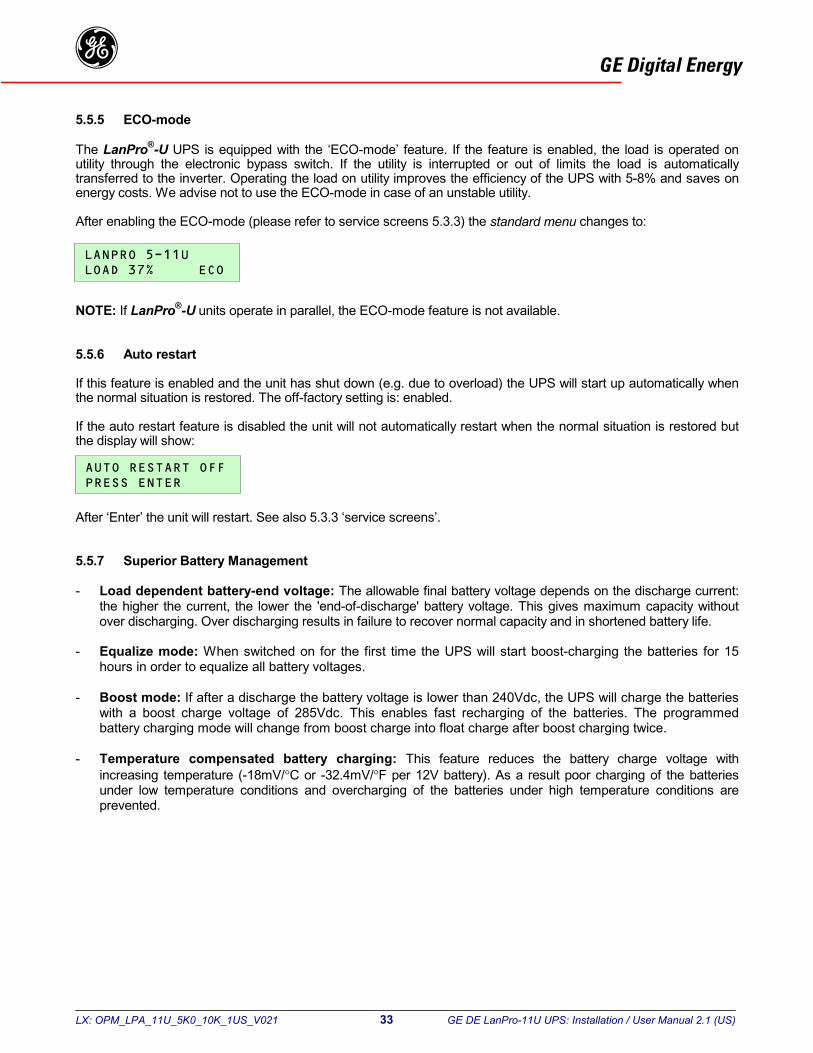
The LanPro®-U UPS is equipped with the ‘ECO-mode’ feature. If the feature is enabled, the load is operated onutility through the electronic bypass switch. If the utility is interrupted or out of limits the load is automaticallytransferred to the inverter. Operating the load on utility improves the efficiency of the UPS with 5-8% and saves onenergy costs. We advise not to use the ECO-mode in case of an unstable utility.
After enabling the ECO-mode (please refer to service screens 5.3.3) the standard menu changes to:
N
5
It
It
A
5
-
-
-
-
OTE: If LanPro®-U units operate in parallel, the ECO-mode feature is not available.
.5.6 Auto restart
f this feature is enabled and the unit has shut down (e.g. due to overload) the UPS will start up automatically whenhe normal situation is restored. The off-factory setting is: enabled.
f the auto restart feature is disabled the unit will not automatically restart when the normal situation is restored buthe display will show:
X: OPM_LPA_11U_5K0_10K_1US_V021 33 GE DE LanPro-11U UPS: Installation / User Manual 2.1 (US)
fter ‘Enter’ the unit will restart. See also 5.3.3 ‘service screens’.
.5.7 Superior Battery Management
Load dependent battery-end voltage: The allowable final battery voltage depends on the discharge current:the higher the current, the lower the 'end-of-discharge' battery voltage. This gives maximum capacity withoutover discharging. Over discharging results in failure to recover normal capacity and in shortened battery life.
Equalize mode: When switched on for the first time the UPS will start boost-charging the batteries for 15hours in order to equalize all battery voltages.
Boost mode: If after a discharge the battery voltage is lower than 240Vdc, the UPS will charge the batterieswith a boost charge voltage of 285Vdc. This enables fast recharging of the batteries. The programmedbattery charging mode will change from boost charge into float charge after boost charging twice.
Temperature compensated battery charging: This feature reduces the battery charge voltage withincreasing temperature (-18mV/°C or -32.4mV/°F per 12V battery). As a result poor charging of the batteriesunder low temperature conditions and overcharging of the batteries under high temperature conditions areprevented.

LX: OPM_LPA_11U_5K0_10K_1US_V021 34 GE DE LanPro-11U UPS: Installation / User Manual 2.1 (US)
GE Digital Energyg
The UPS is equipped with 3 ‘option slots’ (rear panel, 12-14). In the most left slot (12) an RS232/contact interfacecard is factory installed. See 5.1. In the middle slot (13) additional Relay or SNMP plug-in Cards can be installed.The most right slot (14) allows easy installation of an RPA plug–in Card (Redundant Parallel Operation).
6.1 RS232 / contact interface
The RS232/Contact interface (9-pole, sub D, rear panel, 12a) enables advanced communication between theUPS and e.g. a personal computer. An interface kit (cable and software) is delivered with the UPS. The softwaresupports most common operating systems incl. Novell, UNIX, VMS, Windows 3 - 95/98/2000 - NT, IBM OS/2,LINUX, has a modular and layered architecture and works for all degrees of network complexity: stand-alone,multi-vendor networks and large managed networks.During a power failure the UPS software takes a number of actions: processes are stopped, open files are closedand unattended systems will be shut down in a controlled way. When the utility power returns, the systems willautomatically start up and will be up and running as soon as possible.
For specific information on GE Digital Energy’s connectivity products please contact your dealer or internet:www.gedigitalenergy.com.
Pin # Function1 Battery low2 Serial data out3 Serial data in / UPS shutdown4 Not used5 Common6 Bypass active7 Plug&Play / RTS8 Utility failure9 General alarm
contact interface: Max 48V / 30mA
6.2 Emergency shutdown
The emergency shutdown connector is located on the RS232/contact interface card (12). Be sure that the UPS isswitched off, and remove the card from the unit*. Remove the wire from connector J3 (pin 3 and 4). Install the wiringof a normally closed contact to connector J3 (pin 3 and 4). Re-install the RS232 interface card. If during normaloperation of the UPS the contact is opened, the UPS will shut down. To restart the unit, restore the connection andturn the UPS off and on again.
* If the card is removed during normal operation the UPS will shut down.
6.3 Relay Card (optional)
The relay plug-in card can be installed in the middle option slot (rear panel, 13). The card is provided with fourpotential free contacts representing: battery low, bypass active, utility failure and general alarm. For more informationplease refer to the user manual that comes with the interface card.
6.4 SNMP Interface (optional)
This SNMP plug-in card can be installed in the middle option slot (rear panel, 13). The card makes the UPS ‘SNMPmanageable’: it allows the data interface to be connected directly to an Ethernet network (thin coax, twisted pair,AUI). For more information please refer to the user manual that comes with the interface card. When this option isinstalled the RS232 communication link is no longer available.
Fig. 22: RS232 / contact interface
6 - Interfacing Features
GENERAL ALARM
5
COMMON
MAINS FAILURE
DATA TO UPSUPS SHUTDOWN
PnP / RTS
DATA FROM UPS
BYPASS ACTIVE
BATTERY LOW
94837261
DCRS232
DCRS232
DCRS232
LX: OPM_LPA_11U_5K0_10K_1US_V021 35 GE DE LanPro-11U UPS: Installation / User Manual 2.1 (US)
GE Digital Energyg
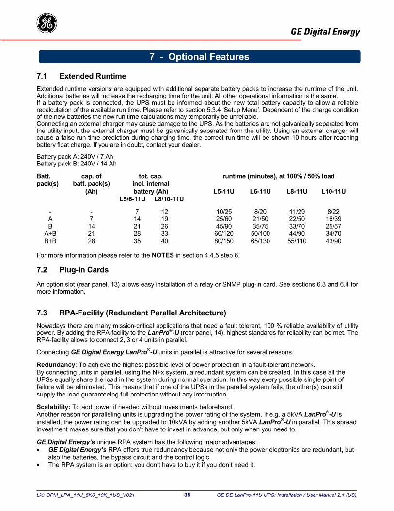
7.1 Extended RuntimeExtended runtime versions are equipped with additional separate battery packs to increase the runtime of the unit.Additional batteries will increase the recharging time for the unit. All other operational information is the same.If a battery pack is connected, the UPS must be informed about the new total battery capacity to allow a reliablerecalculation of the available run time. Please refer to section 5.3.4 ‘Setup Menu’. Dependent of the charge conditionof the new batteries the new run time calculations may temporarily be unreliable.Connecting an external charger may cause damage to the UPS. As the batteries are not galvanically separated fromthe utility input, the external charger must be galvanically separated from the utility. Using an external charger willcause a false run time prediction during charging time, the correct run time will be shown 10 hours after reachingbattery float charge. If you are in doubt, contact your dealer.
Battery pack A: 240V / 7 AhBattery pack B: 240V / 14 Ah
Batt. cap. of tot. cap. runtime (minutes), at 100% / 50% loadpack(s) batt. pack(s) incl. internal
(Ah) battery (Ah) L5-11U L6-11U L8-11U L10-11UL5/6-11U L8/10-11U
- - 7 12 10/25 8/20 11/29 8/22A 7 14 19 25/60 21/50 22/50 16/39B 14 21 26 45/90 35/75 33/70 25/57
A+B 21 28 33 60/120 50/100 44/90 34/70B+B 28 35 40 80/150 65/130 55/110 43/90
For more information please refer to the NOTES in section 4.4.5 step 6.
7.2 Plug-in Cards
An option slot (rear panel, 13) allows easy installation of a relay or SNMP plug-in card. See sections 6.3 and 6.4 formore information.
7.3 RPA-Facility (Redundant Parallel Architecture)Nowadays there are many mission-critical applications that need a fault tolerant, 100 % reliable availability of utilitypower. By adding the RPA-facility to the LanPro®-U (rear panel, 14), highest standards for reliability can be met. TheRPA-facility allows to connect 2, 3 or 4 units in parallel.
Connecting GE Digital Energy LanPro®-U units in parallel is attractive for several reasons.
Redundancy: To achieve the highest possible level of power protection in a fault-tolerant network.By connecting units in parallel, using the N+x system, a redundant system can be created. In this case all theUPSs equally share the load in the system during normal operation. In this way every possible single point offailure will be eliminated. This means that if one of the UPSs in the parallel system fails, the other(s) can stillsupply the load guaranteeing full protection without any interruption.
Scalability: To add power if needed without investments beforehand.Another reason for paralleling units is upgrading the power rating of the system. If e.g. a 5kVA LanPro®-U isinstalled, the power rating can be upgraded to 10kVA by adding another 5kVA LanPro®-U in parallel. This spreadinvestment makes sure that you don’t have to invest in advance, but only when you need to.
GE Digital Energy’s unique RPA system has the following major advantages:• GE Digital Energy’s RPA offers true redundancy because not only the power electronics are redundant, but
also the batteries, the bypass circuit and the control logic,• The RPA system is an option: you don’t have to buy it if you don’t need it.
7 - Optional Features
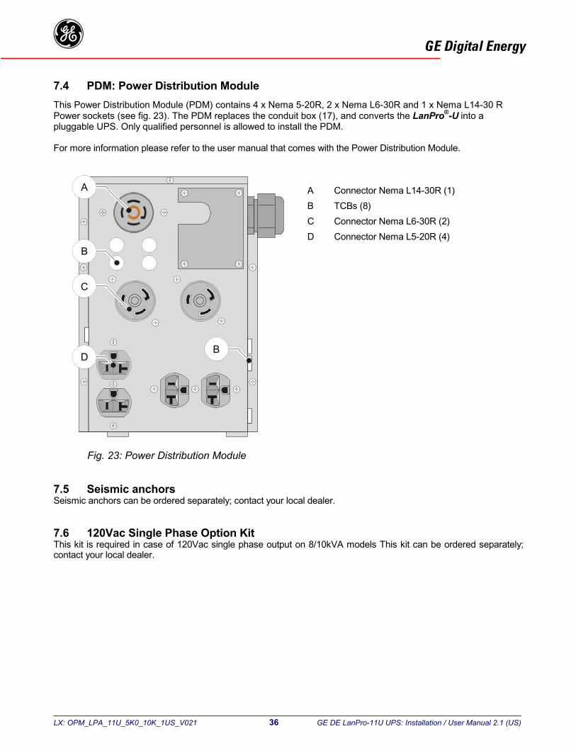
LX: OPM_LPA_11U_5K0_10K_1US_V021 36 GE DE LanPro-11U UPS: Installation / User Manual 2.1 (US)
GE Digital Energyg7.4 PDM: Power Distribution ModuleThis Power Distribution Module (PDM) contains 4 x Nema 5-20R, 2 x Nema L6-30R and 1 x Nema L14-30 RPower sockets (see fig. 23). The PDM replaces the conduit box (17), and converts the LanPro®-U into apluggable UPS. Only qualified personnel is allowed to install the PDM.
For more information please refer to the user manual that comes with the Power Distribution Module.
A Connector Nema L14-30R (1)B TCBs (8)C Connector Nema L6-30R (2)D Connector Nema L5-20R (4)
7.5 Seismic anchorsSeismic anchors can be ordered separately; contact your local dealer.
7.6 120Vac Single Phase Option KitThis kit is required in case of 120Vac single phase output on 8/10kVA models This kit can be ordered separately;contact your local dealer.
A
B
DB
C
Fig. 23: Power Distribution Module
LX: OPM_LPA_11U_5K0_10K_1US_V021 37 GE DE LanPro-11U UPS: Installation / User Manual 2.1 (US)
GE Digital Energyg
8.1 General
When used properly, the UPS is virtually maintenance free other than keeping the air inlets/outlets free from dust.
8.2 Cooling fan
The expected operational life of the cooling fans is approximately 20,000 to 40,000 hours of continuous operation. Ahigh ambient temperature will shorten this operational life.
8.3 Batteries
The service life of the battery is from 3 to 6 years, depending on the operating temperature and on the number ofdischarge cycles.As a healthy battery is essential to the performance of the UPS, an automatic battery test is performed regularly toensure failsafe operation (see section 5.4.1). When the condition of the battery is critical, the warning signal will beactivated (buzzer 1x per 8 secs, and alarm message 'Replace battery', see 5.3.2). The batteries must be replacedas soon as possible. Please contact your dealer. Use only UL recognised batteries (BAZR2), valve regulatedtypes.
NOTE: under certain circumstances a manual battery test can result in a false alarm: please see section 5.4.2'QUICK BATTERY TEST'.
Regular deep battery tests are advised in order to re-calibrate the capacity of aging batteries. See section 5.4.3 formore information.
NOTE: All maintenance and service work, including battery replacement, should be performed by qualifiedservice personnel.
For authorized service personnel only:Never short the battery terminals. Shorting may cause the battery to burn. Avoid charging in a sealed container.Proper disposal of batteries is required: refer to your local codes for disposal requirements. Never dispose ofbatteries in a fire: they may explode. Never disassemble or reassemble batteries; their contents (electrolyte) may beextremely toxic. If exposed to electrolyte, wash immeditately with plenty of water, if eye contact occurs flush withwater and contact a physician.
8.4 Safety
CAUTION:When the LanPro®-U UPS is operating, all parts of the electronics are directly connected to the utility andhigh voltages are present on all internal parts, including the battery. Even after disconnection from theutility, all parts inside the LanPro®-U UPS, including the battery, conduct dangerous voltages (except theRS232 output).
For your safety, only authorized service personnel may remove the cabinet cover.
8.5 Storage
Always store the UPS in a dry location with the batteries in a fully charged state, storage temperature must be within-20 and +45°C. Storing the unit for a period exceeding 3 months can reduce the life of the batteries. To maintaintheir normal life expectancy, the batteries must be recharged periodically:- if the storage temperature is within -20 and +30°C (-4°F and 86°F): every 6 months, for 24 hours,- if the storage temperature is within -20 and +45°C (-4°F and 113°F): every 4 months, for 24 hours.
8 - Maintenance
L
GE Digital Energyg
Whenever a malfunction occurs, first check external factors (e.g connections, temperature, humidity or load) todetermine whether the problem is caused by the unit itself or by its environment. Subsequently check whether thebreakers/switches on the rear panel (fig. 19, 7-8-9) are in ‘on’ position. Always check these external factors beforeconcluding that your LanPro®-U UPS is faulty.The front screen will indicate the problem and solution (if the problem is due to environmental circumstances). If thesolution is not shown on the screen, please contact your dealer.
During the self-test, performed immediately after start-up, the UPS may detect a system failure. In this case amessage is displayed for 30 seconds before the self-test is repeated. If the faulty situation persists, please contactyour dealer.
(One of) the following messages can be displayed:
One or more voltages of the internal power supply is (are) outside tolerance.Please contact your dealer.
*tl
9 - Troubleshooting
An external AC voltage (not the UPSs output voltage) was detected on theoutput terminals. Please contact your dealer.
The internal battery fuse is defective. Please contact your dealer.
The battery extension circuit breaker is in 'the off' position. Please switch it to'the on' position.
Malfunction of the battery charger. Please contact your dealer.
Malfunction of the input circuit: voltage delivered is too high. Please contact yourdealer.
The temperature of (one of) the components is (still) too high. See section5.3.2.
The battery voltage is too low to allow start-up. Wait for a few hours, leave theUPS switched on.*
Malfunction of input circuit: voltage delivered is too low. The batteries may befaulty or depleted. Wait for a few hours, leave the UPS switched on.*
Hardware output voltage detection 'Q4' is active. Please contact your dealer.
X: OPM_LPA_11U_5K0_10K_1US_V021 38 GE DE LanPro-11U UPS: Installation / User Manual 2.1 (US)
If absence of input power (utility failure, maintenance work) is expected to last longer than a few hours, switch offhe UPS to save battery power. If the UPS input power is absent for several days and the UPS remains on under no-oad conditions, the batteries can be discharged very deeply, resulting in a short battery life time.
LX: OPM_LPA_11U_5K0_10K_1US_V021 39 GE DE LanPro-11U UPS: Installation / User Manual 2.1 (US)
GE Digital Energyg
UPS Type : L5-11U L6-11U L8-11U L10-11UOutput power (kVA/kW) : 5/4 6/4.8 8/6.4 10/8AC input voltage : 120/208/240 Vac (120V only with step-up transformer for L5/6-11U)Input frequency : 60/50 HzAC output voltage : 120/208/220/230/240VOutput frequency : 60 or 50 Hz, std. 60 Hz; selectable on frontSystem efficiency (full load) : 87%Line input breaker (C-type) : 32A 32A 50A 63ABypass input breaker (C-type) : 32A 32A 50A 63ABattery safety fuse (F4A) : 30A 30A 30A 30ABattery safety fuse (F4B) : 30A (spare) 30A (spare) 30A 30AInternal safety fuse (F5A) : - - 30A 30AInternal safety fuse (F5B) : 30A 30A 30A 30AInput/output connectors : terminals at rear of unit
INPUTAC input voltage range (208V-240V)
at 100% load : 162 - 285 Vat 50% load : 146 - 285 Vat 20% load : 133 - 285 V
AC input voltage range (120V, L5/6-11U)at 100% load : 81 - 141 Vat 50% load : 72 - 141 Vat 20% load : 66 - 141 V
Input frequency range : 40-70 HzInput current wave form : sinusoidalInput power factor : ≥ 0.99Max. input current at 100% load 120V : 43.3A 50.8A n.a. n.a.
208V : 25.0A 30.0A 40.5 50.3240V : 21.4A 25.1 34.8 42.0
Inrush current : noneRectified DC voltage out : 380 V
BATTERY CHARGERCharacteristic : U/I-characteristic, constant current charging until boost/float voltage, then
constant voltage charging and boost charge mode for fast recharging of batteriesDC input voltage range : 350-450 VDC output voltage at 20 °C : float: 273 V boost: 295 VOutput current limit (Adc) : 2.0 2.0 3.0 3.0
OUTPUT CONVERTEROutput power at pf. = 0.8, VA* : 5000 6000 8000 10000Semiconductor : IGBTAC output voltage : 120/208/240V ± 1% static resistive load
120/208/240V ± 2% measured crest load 2.5:1120/208/240V ± 2% dynamic mean deviation over one half cycle for 100% ofrated load applied or removed
Typical overload : 110% ≥ 20 minutes(temp. dependent) 130% ≥ 3.5 minutes
150% ≥ 2 minutesOutput frequency : 60 or 50 Hz selectable, ± 0.1%, unless synchronized with the utilityFreq. tracking range : ± 2/4/6% of nominal, user selectableOutput wave form : sine waveMax. phase difference input-output : max 7°Harmonic distortion : 2% max. with linear loadPower factor range : Any lagging or leading power factor permitted within the specified rating to pf. 0.5Output derating altitude : Till 1000m no derating
Above 1000m 12.5% per 1000m, max. 4000mProtection : Automatic shut down (or transfer to bypass, if bypass is available) in case of
- low/high DC voltage- overtemperature- overload / short circuit
The output is protected against connection to the utility supply* according to EN 50091-1
10 - Specifications
LX: OPM_LPA_11U_5K0_10K_1US_V021 40 GE DE LanPro-11U UPS: Installation / User Manual 2.1 (US)
GE Digital EnergygUPS Type : L5-11U L6-11U L8-11U L10-11U
AUTOMATIC BYPASS SWITCHThe automatic switch provides transfer of the load to the utility voltage without any interruption of the supply. The transfer isinitiated by a signal from the output converter protection circuit in case of an overload or high temperature.When the conditions return to normal the load is automatically transferred back to the output converter. The automatic bypassswitch can be disabled by the end-user.
Bypass voltage limits : -15%, +10% of nominalTransfer transients : typically 2% mean deviation over one half cycle.Frequency tracking range : ± 2/4/6% of nominal (user selectable)Slew rate : max. 1Hz/sec or 5Hz/sec (user selectable)
BATTERYBattery type : Sealed and maintenance freeNominal voltage (V) / capacity (Ah) : 12/7 12/7 12/12 12/12Number of batteries : 20 20 20 20Capacity of standard battery set : 7Ah 7Ah 12Ah 12AhBattery recharge time : 1.5 - 3 hours for 80% capacityBattery service life : up to 6 years (depending on operating conditions)Battery discharging : self discharge current ≤ 0.35 mA
discharge end voltage of the battery depending on the actual load10.5Vdc < 0.2 CA till 9.0 Vdc > 2 CAWhen the UPS is in sleeping mode the inverter will be switched off, batterycharger and rectifier are in operation
Runtime in minutesVA / Watts1000 / 800 : 60 60 120 1202000 / 1600 : 40 40 60 603000 / 2400 : 18 18 40 405000 / 4000 : 10 10 22 226000 / 4800 : - 8 17 178000 / 6400 : - - 11 1110000 / 8000 : - - - 8
BATTERY EXTENSION PACKSSheet steel cubicle : VSDA1Dimensions (hxwxd, mm) : 537x313x590Dimensions (hxwxd, inch) : 21.1x12.3x23.2Battery : 240Vdc/7Ah or 240Vdc/14AhWeight with battery (Kg) : 73 or 123Weight with battery (Lbs) : 161 or 271
Battery pack A (voltage V / capacity Ah) : 240/7 240/7 240/7 240/7Total capacity (Ah) : 14 14 19 19Typical runtime, 100% / 50% load, min. : 25/60 21/50 22/50 16/39Number of packs required : 1 1 1 1
Battery pack B (voltage V / capacity Ah) : 240/14 240/14 240/14 240/14Total capacity (Ah) : 21 21 26 26Typical runtime, 100% / 50% load, min. : 45/90 35/75 33/70 25/57Number of packs required : 1 1 1 1
For more info see section 7.1
STEP-UP TRANSFORMER CABINET MOUNTED UNDERNEATH VSD2 (FOR LANPRO-U 5/6-11U ONLY)Sheet steel cubicle : VSDT2 + VSD2Dimensions (hxwxd, mm) : 995x313x730Dimensions (hxwxd, inch) : 39.2x12.3x28.7Weight (Kg) : 175 KgWeight (Lbs) : 386 Lbs

LX: OPM_LPA_11U_5K0_10K_1US_V021 41 GE DE LanPro-11U UPS: Installation / User Manual 2.1 (US)
GE Digital EnergygUPS Type : L5-11U L6-11U L8-11U L10-11U
ENCLOSURESheet steel cubicle : VSD2 VSD2 VSD2 VSD2Colour front : RAL 9006 (aluminum)Colour cabinet : RAL 9010 (white)Protection : IP 20Dimensions (hxwxd, mm) : 680x313x730 680x313x730 680x313x730 680x313x730Dimensions (hxwxd, inch) : 26.8x12.3x28.7 26.8x12.3x28.7 26.8x12.3x28.7 26.8x12.3x28.7(height with castors)Weight (with batteries, Kg) : 134 kg 134 kg 175 kg 186 kgWeight (with batteries, Lbs) : 295 Lbs 295 Lbs 386 Lbs 410 Lbs
GENERAL DESIGN CRITERIAMechanical : IP20Humidity : 95% non condensingSafety : UL 1778; 2001, C-UL
EN 50091-1-1: 1999; EN 60950 / IEC 950: 2001Surge capability : 6kV 1.2/50µs; 3kA 8/20µsEMC : FCC part 15, class A; EN 50091-2
ENVIRONMENTAmbient temperature : -10 to +40°C (14 to 104°F)Audible noise at 1 meter : 40 - 50dB(A),
the audible noise is load and temperature dependent

LX: OPM_LPA_11U_5K0_10K_1US_V021 42 GE DE LanPro-11U UPS: Installation / User Manual 2.1 (US)
GE Digital EnergygDimensions conduit box
Front
WD
HW= 155mm/ 6.1 InchD= 300mm/ 11.8 InchH= 275mm/ 10.8 Inch
VSD2: h x w x d680 x 310 x 710 mm26.8 x 12.2 x 28 Inch
Center of gravity

GE Digital EnergygLanPro® 5/6/8/10-11U installation drawings
Model Heat dissipationLinear load 240 Volt
Dimensions Air flow100%load
Rel.humidity
non-cond.
Altitude(max 4000m)
Input wiring Output wiring
100% load 50% load h w d
Weight Amb.temp.
utility volt.120V
utility volt.208V
utility volt.240V
outputvolt. 120V
outputvolt. 208V
outputvolt. 240V
LanPro W Btu/hr W Btu/hr Inch Inch Inch Lbs m3/hr °F m AWG/mm2 AWG/mm2 AWG/mm2 AWG/mm2 AWG/mm2 AWG/mm2
5-11U 571 1950 389 1329 26.8 12.3 28.7 295 660 14-104 <95 N.A. 10/6 10/6 8/10 10/6 10/66-11U 661 2254 381 1300 26.8 12.3 28.7 295 660 14-104 <95 N.A. 8/10 10/6 8/10 10/6 10/68-11U 948 3234 551 1882 26.8 12.3 28.7 386 660 14-104 <95 N.A. 6/14 8/10 6/14 8/10 8/1010-11U 1090 3719 556 1896 26.8 12.3 28.7 410 660 14-104 <95 N.A. 4/22 6/14 4/22 8/10 8/105-11U/120 V 641 2187 425 1451 39.2 12.3 28.7 386 660 14-104 <95 6/14 N.A. N.A. 8/10 10/6 10/66-11U/120 V 744 2539 601 2051 39.2 12.3 28.7 386 660 14-104 <95
<1000, derating12.5% per 1000
4/22 N.A. N.A. 8/10 10/6 10/6
Model Minimum free space required(Inches)
front side rear
Distance between mountingholes (Inches)
Input overcurrent protection(AMPS)
Output overcurrent protection (AMPS)
x y z 120V 208V 240V 120V(1 X)
120V(2X)
208V 240V
L5-11U 4 2 8 7.24 22.76 7.48 35 30 40 20 25 20L5-11U /120V 4 2 8 7.24 22.76 7.48 60 40 20 25 20L6-11U 4 2 8 7.24 22.76 7.48 40 35 50 25 30 25L6-11U /120V 4 2 8 7.24 22.76 7.48 70 50 25 30 25L8-11U 4 2 8 7.24 22.76 7.48 60 45 70 35 40 35L10-11U 4 2 8 7.24 22.76 7.48 70 60 80 40 50 40
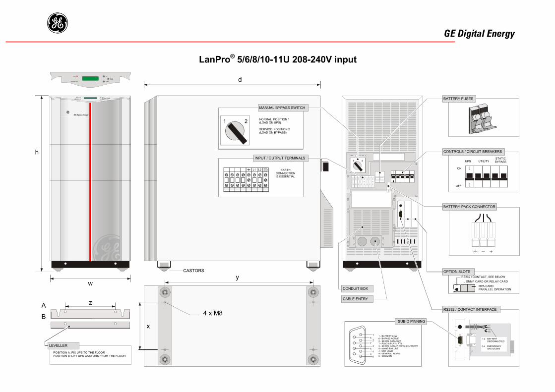
GE Digital EnergygLanPro® 5/6/8/10-11U 208-240V input
MANUAL BYPASS SWITCH
INPUT / OUTPUT TERMINALS
BATTERY FUSES
CONTROLS / CIRCUIT BREAKERS
BATTERY PACK CONNECTOR
OPTION SLOTS
RS232 / CONTACT INTERFACE
SUB-D PINNING
NORMAL: POSITION 1(LOAD ON UPS)
SERVICE: POSITION 2(LOAD ON BYPASS)
EARTHCONNECTIONIS ESSENTIAL
UPS UTILITYSTATICBYPASS
ON
OFF
1-2 BATTERYDISCONNECTED
3-4 EMERGENCYSHUTDOWN
RS232 / CONTACT, SEE BELOWSNMP CARD OR RELAY CARD
RPA CARDPARALLEL OPERATION
1 - BATTERY LOW6 - BYPASS ACTIVE2 - SERIAL DATA OUT7 - PLUG & PLAY / RTS3 - SERIAL DATA IN / UPS SHUTDOWN8 - MAINS FAILURE4 - NOT USED9 - GENERAL ALARM5 - COMMON
x
y
4 x M8
w
CASTORS
h
d
CONDUIT BOX
CABLE ENTRY
A
B
POSITION A: FIX UPS TO THE FLOORPOSITION B: LIFT UPS CASTORS FROM THE FLOOR
LEVELLER
z
L1 L2
���
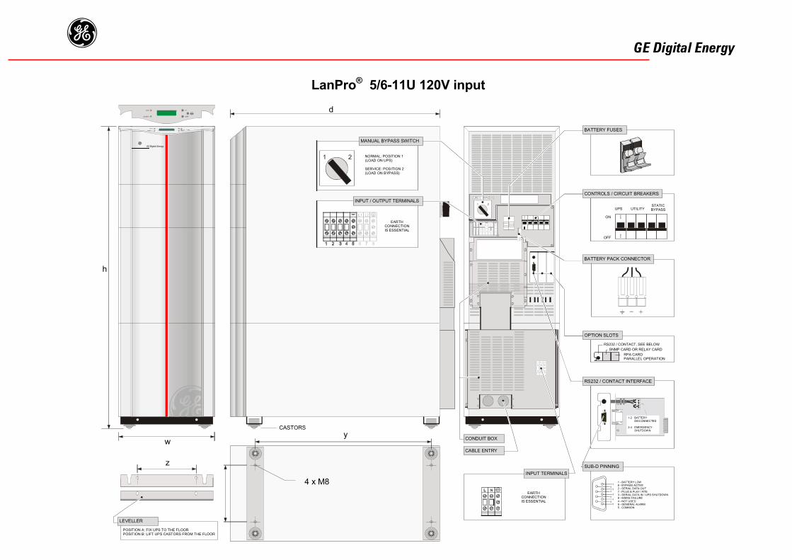
GE Digital Energyg LanPro® 5/6-11U 120V input
MANUAL BYPASS SWITCH
NORMAL: POSITION 1(LOAD ON UPS)
SERVICE: POSITION 2(LOAD ON BYPASS)
EARTHCONNECTIONIS ESSENTIAL
UPS UTILITYSTATICBYPASS
ON
OFF
RS232 / CONTACT, SEE BELOWSNMP CARD OR RELAY CARD
RPA CARDPARALLEL OPERATION
1-2 BATTERYDISCONNECTED
3-4 EMERGENCYSHUTDOWN
1 - BATTERY LOW6 - BYPASS ACTIVE2 - SERIAL DATA OUT7 - PLUG & PLAY / RTS3 - SERIAL DATA IN / UPS SHUTDOWN8 - MAINS FAILURE4 - NOT USED9 - GENERAL ALARM5 - COMMON
INPUT / OUTPUT TERMINALS
BATTERY FUSES
CONTROLS / CIRCUIT BREAKERS
BATTERY PACK CONNECTOR
OPTION SLOTS
RS232 / CONTACT INTERFACE
SUB-D PINNING
EARTHCONNECTIONIS ESSENTIAL
INPUT TERMINALS
CONDUIT BOX
CABLE ENTRY
d
h
w
z
y
POSITION A: FIX UPS TO THE FLOORPOSITION B: LIFT UPS CASTORS FROM THE FLOOR
LEVELLER
4 x M8
CASTORS
���������