Lowering a Cofferdam: Alternate Means to … MOVABLE STRUCTURES, INC. SIXTEENTH BIENNIAL SYMPOSIUM...
15
HEAVY MOVABLE STRUCTURES, INC. SIXTEENTH BIENNIAL SYMPOSIUM September 19-22, 2016 Lowering a Cofferdam: Alternate Means to Constructing a Cofferdam Tyler D. VanderLinden, P.E.; PCL Civil Constructors, Inc. Tom Petray, P.E.; Bittner-Shen Consulting Engineers, Inc. TAMPA MARRIOTT WATERSIDE HOTEL AND MARINA TAMPA, FLORIDA
Transcript of Lowering a Cofferdam: Alternate Means to … MOVABLE STRUCTURES, INC. SIXTEENTH BIENNIAL SYMPOSIUM...
HEAVY MOVABLE STRUCTURES, INC.
SIXTEENTH BIENNIAL SYMPOSIUM
September 19-22, 2016
Lowering a Cofferdam: Alternate Means to Constructing a
Cofferdam
Tyler D. VanderLinden, P.E.; PCL Civil Constructors, Inc.
Tom Petray, P.E.; Bittner-Shen Consulting Engineers, Inc.
TAMPA MARRIOTT WATERSIDE HOTEL AND MARINA
TAMPA, FLORIDA
Lowering a Cofferdam – Alternate Means to Constructing a Cofferdam
HEAVY MOVABLE STRUCTURES, INC.
16th Biennial Movable Bridge Symposium 2
LOWERING A COFFERDAM:
ALTERNATE MEANS TO CONSTRUCTING A COFFERDAM Tyler D. VanderLinden, P.E.; PCL Civil Constructors, Inc.; Seattle, Washington
Tom Petray, P.E.; Bittner-Shen Consulting Engineers, Inc.; Denver, Colorado
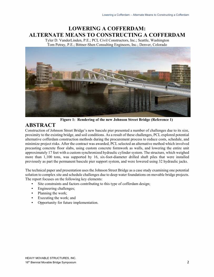
Figure 1: Rendering of the new Johnson Street Bridge (Reference 1)
ABSTRACT Construction of Johnson Street Bridge’s new bascule pier presented a number of challenges due to its size,
proximity to the existing bridge, and soil conditions. As a result of these challenges, PCL explored potential
alternative cofferdam construction methods during the procurement process to reduce costs, schedule, and
minimize project risks. After the contract was awarded, PCL selected an alternative method which involved
precasting concrete floor slabs, using custom concrete formwork as walls, and lowering the entire unit
approximately 17 feet with a custom synchronized hydraulic cylinder system. The structure, which weighed
more than 1,100 tons, was supported by 16, six-foot-diameter drilled shaft piles that were installed
previously as part the permanent bascule pier support system, and were lowered using 32 hydraulic jacks.
The technical paper and presentation uses the Johnson Street Bridge as a case study examining one potential
solution to complex site and schedule challenges due to deep water foundations on movable bridge projects.
The report focuses on the following key elements:
• Site constraints and factors contributing to this type of cofferdam design;
• Engineering challenges;
• Planning the work;
• Executing the work; and
• Opportunity for future implementation.
Lowering a Cofferdam – Alternate Means to Constructing a Cofferdam
HEAVY MOVABLE STRUCTURES, INC.
16th Biennial Movable Bridge Symposium 3
INTRODUCTION In December 2012, PCL Constructors Westcoast, Inc. was awarded the contract for replacement of the
existing Johnson Street Bridge (“JSB”) in Victoria, British Columbia, Canada. The current Johnson Street
Bridge, built 90-years ago, is a bascule bridge spanning the Inner Harbour of Victoria, British Columbia.
The new bridge features a main bascule span in a parallel alignment to the existing bridge, and includes
three lanes of traffic, two bicycle lanes, a pedestrian walkway, a multiuse walkway, and a walkway through
the bascule “rings” that allow pedestrians to see how the bridge operates during openings. Once complete,
the main span will be the longest single leaf bascule bridge in Canada. The one-of-a-kind bridge will feature
tapering truss sections and varying geometry on the walkways.
The new bridge will be powered by hydraulic motors and gearing. The existing span, along with a parallel
rail span, will be removed as part of the bridge replacement project
Following contract award, PCL evaluated various cofferdam concepts to construct the in-water bascule
pier. A traditional driven pile design, precast float-in design, and a design in which the cofferdam was
lowered using the previously constructed drilled shafts were all options PCL considered.
The following is a list of advantages and disadvantages the
selected concept had over the other options:
• Advantages:
o Cofferdam can be used as formwork
(cost savings);
o Minimal environmental and existing
structure impacts;
o Not dependent on site subsurface
conditions; and
o Reduced critical path schedule from
traditional sheet pile cofferdam
construction;
o Flexibility with on-going design
changes.
• Disadvantages:
o Schedule could be further accelerated
with pre-cast float-in (non-
concurrent with shaft
construction);
o Engineering intensive (complex and integrated engineering); and
o Subsurface conditions caused pile locations to vary complicating the design of the
bottom slab.
The net result was a cofferdam design that required more technical effort but offered significant cost savings
over conventional cofferdams.
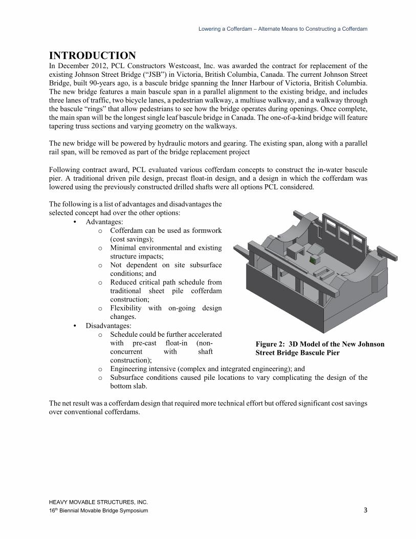
Figure 2: 3D Model of the New Johnson
Street Bridge Bascule Pier
Lowering a Cofferdam – Alternate Means to Constructing a Cofferdam
HEAVY MOVABLE STRUCTURES, INC.
16th Biennial Movable Bridge Symposium 4
ALTERNATIVE FLOAT-IN COFFERDAM Float-in cofferdams have been used on several major bridge projects in the United States and Canada
including the Bath–Woolwich Bridge in Maine in 1998 and the Port Mann Bridge in Vancouver, British
Columbia in 2009 (See reference 2 & 3). The cofferdam utilized for the Johnson Street Bridge is very
similar to its float-in predecessors. However, the new Johnson Street Bridge cofferdam was constructed by
suspending the components from the production drilled shaft piles and then lowered into place. Some
characteristics the Johnson Street Bridge cofferdam shared with traditional float-in cofferdams include:
• A concrete bottom slab in the shape of a footing to act as both a cofferdam and a bottom form for
the pile cap concrete placement.
• Tremie grouting of the annulus between the concrete shell and the production piles to seal the
bottom of the cofferdam to the piles.
• A steel follower cofferdam to extend the height of the cofferdam to allow for submergence,
construction in the dry, and function as wall forms.
• An internal bracing system to resist the hydrostatic pressure.
Some elements of the Johnson Street Bridge cofferdam that differed from a traditional float-in cofferdam
include:
• Casting of modular precast panels to provide formwork for in-plan construction of the cofferdam
base slab.
• Suspension of the precast formwork panels from the production piles over the high water elevation.
• Placement of cofferdam base slab reinforcing and concrete over the water.
• Construction of the steel follower cofferdam over the water.
• Lowering of the cofferdam with a synchronized hydraulic jacking system.
• Use of only the bond-shear capacity of the grouted annulus between the base slab and the
production piles to resist hydrostatic uplift during the cofferdam dewatering and the downward
force during construction of the pier footing at low tide elevations.
DESIGN The design used to lower the cofferdam with permanent drilled shaft piles involved five distinct elements:
precast formwork panels, cofferdam base slab, steel wall forms and bracing, lowering system, and tremie
concrete annulus.
PRECAST FORMWORK PANELS The formwork for the cofferdam base slab consisted of 16 precast panels in 10 slightly different sizes. Each
of the precast formwork panels consisted of a 6.5 inch thick slab, an eight-foot-in-diameter corrugated pipe
penetration, and a one-foot-thick drop panel at the pile interface. While the span for the precast slab was
nearly 20 feet, it was utilized only as a form for the cofferdam base slab construction. This helped expedite
schedule through quicker installation and elimination of removal. Due to site constraints, removing
traditional falsework and formwork would be extremely difficult.
Lowering a Cofferdam – Alternate Means to Constructing a Cofferdam
HEAVY MOVABLE STRUCTURES, INC.
16th Biennial Movable Bridge Symposium 5
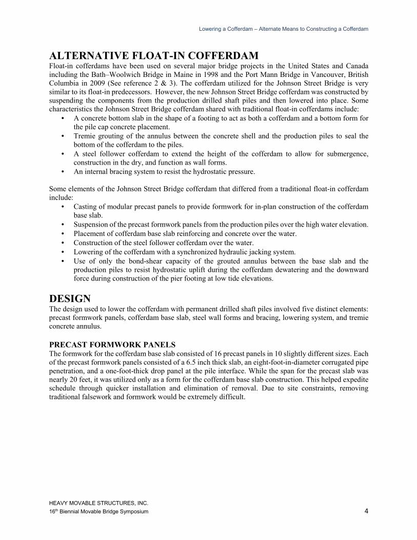
Figure 3: Precast Panel Slab Configuration
The precast formwork panels utilized 6,500 psi concrete to reduce the weight. Due to site and crane
restraints the panels for this project had a 55,000 pound weight limit. The perimeter panels were constructed
with a two-foot-tall curb to act as the side form for the cofferdam base slab. Given the complicated geometry
and boundary conditions of the suspended formwork, a finite element analysis of the formwork panels was
conducted in SAP2000 to determine maximum bending moment and shear values for design. Each of the
16 panels were suspended around a production drilled shaft pile and connected together by steel embed and
splice plates. High strength threaded rods embedded in the drop panels where used to suspend the panels
from the lowering system. The precast formwork panels weighed a total of 284 tons.
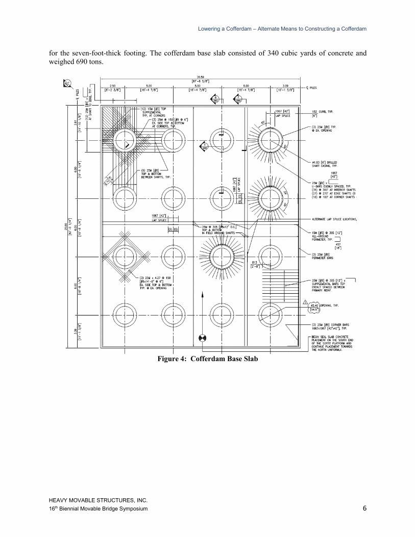
COFFERDAM BASE SLAB After completing the formwork panel erection, the cofferdam base slab was constructed. The precast
formwork allowed PCL to construct the heavy cofferdam base slab onsite and above the high water
elevation of the Victoria Inner Harbour in dry conditions. The base slab consisted of a two-foot-thick
concrete two-way slab.
There were two primary loading conditions for design of the base slab; hydrostatic uplift and concrete
footing placement. The controlling load combination was for footing concrete placement at low tide. The
design load for the cofferdam base slab was over 1,500 pounds-per-square-foot to support the wet concrete
Lowering a Cofferdam – Alternate Means to Constructing a Cofferdam
HEAVY MOVABLE STRUCTURES, INC.
16th Biennial Movable Bridge Symposium 6
for the seven-foot-thick footing. The cofferdam base slab consisted of 340 cubic yards of concrete and
weighed 690 tons.
Figure 4: Cofferdam Base Slab
Lowering a Cofferdam – Alternate Means to Constructing a Cofferdam
HEAVY MOVABLE STRUCTURES, INC.
16th Biennial Movable Bridge Symposium 7
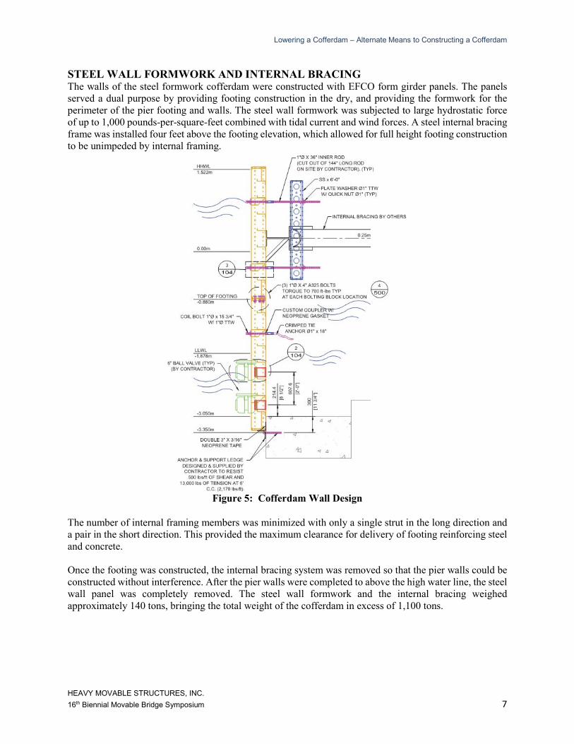
STEEL WALL FORMWORK AND INTERNAL BRACING The walls of the steel formwork cofferdam were constructed with EFCO form girder panels. The panels
served a dual purpose by providing footing construction in the dry, and providing the formwork for the
perimeter of the pier footing and walls. The steel wall formwork was subjected to large hydrostatic force
of up to 1,000 pounds-per-square-feet combined with tidal current and wind forces. A steel internal bracing
frame was installed four feet above the footing elevation, which allowed for full height footing construction
to be unimpeded by internal framing.
Figure 5: Cofferdam Wall Design
The number of internal framing members was minimized with only a single strut in the long direction and
a pair in the short direction. This provided the maximum clearance for delivery of footing reinforcing steel
and concrete.
Once the footing was constructed, the internal bracing system was removed so that the pier walls could be
constructed without interference. After the pier walls were completed to above the high water line, the steel
wall panel was completely removed. The steel wall formwork and the internal bracing weighed
approximately 140 tons, bringing the total weight of the cofferdam in excess of 1,100 tons.
Lowering a Cofferdam – Alternate Means to Constructing a Cofferdam
HEAVY MOVABLE STRUCTURES, INC.
16th Biennial Movable Bridge Symposium 8
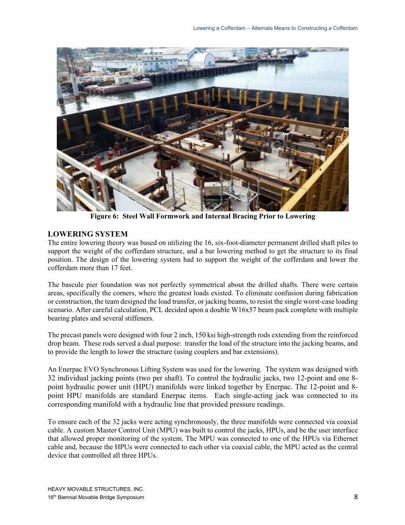
Figure 6: Steel Wall Formwork and Internal Bracing Prior to Lowering
LOWERING SYSTEM The entire lowering theory was based on utilizing the 16, six-foot-diameter permanent drilled shaft piles to
support the weight of the cofferdam structure, and a bar lowering method to get the structure to its final
position. The design of the lowering system had to support the weight of the cofferdam and lower the
cofferdam more than 17 feet.
The bascule pier foundation was not perfectly symmetrical about the drilled shafts. There were certain
areas, specifically the corners, where the greatest loads existed. To eliminate confusion during fabrication
or construction, the team designed the load transfer, or jacking beams, to resist the single worst-case loading
scenario. After careful calculation, PCL decided upon a double W16x57 beam pack complete with multiple
bearing plates and several stiffeners.
The precast panels were designed with four 2 inch, 150 ksi high-strength rods extending from the reinforced
drop beam. These rods served a dual purpose: transfer the load of the structure into the jacking beams, and
to provide the length to lower the structure (using couplers and bar extensions).
An Enerpac EVO Synchronous Lifting System was used for the lowering. The system was designed with
32 individual jacking points (two per shaft). To control the hydraulic jacks, two 12-point and one 8-
point hydraulic power unit (HPU) manifolds were linked together by Enerpac. The 12-point and 8-
point HPU manifolds are standard Enerpac items. Each single-acting jack was connected to its
corresponding manifold with a hydraulic line that provided pressure readings.
To ensure each of the 32 jacks were acting synchronously, the three manifolds were connected via coaxial
cable. A custom Master Control Unit (MPU) was built to control the jacks, HPUs, and be the user interface
that allowed proper monitoring of the system. The MPU was connected to one of the HPUs via Ethernet
cable and, because the HPUs were connected to each other via coaxial cable, the MPU acted as the central
device that controlled all three HPUs.
Lowering a Cofferdam – Alternate Means to Constructing a Cofferdam
HEAVY MOVABLE STRUCTURES, INC.
16th Biennial Movable Bridge Symposium 9
The MPU screen shows each manifold as a separate tab, and each manifold tab shows each jack associated
with that particular manifold. PCL’s internal engineering department designed the overall lowering system
and calculated the expected loads at each jack location. The expected load value for each jack was input
into the MPU. If the pressure in the hydraulic lines exceeded that value, then the entire system stopped and
could only operate again after manual input from the user. This was an exceptional safety device integrated
into the system that helped prevent any major overloading scenarios. There were other safety inputs such
as out of level maximums that also allowed confidence in the operation.
Victoria’s Inner Harbour is a narrow inlet off the Strait of Juan de Fuca which connects the Puget Sound
and Salish Sea to the Pacific Ocean. On any given day, the tidal fluctuations are in excess of eight feet. This
tidal shift, coupled with the narrow properties of the channel, created significant currents, which the
structure had to withstand without moving during lowering. As a result, a lateral jacking system was
designed to help deal with these tidal fluctuations and keep the cofferdam lowering concentrically around
the shafts. Each of the 8 lateral jacking assemblies consisted of a 30 ton jack nested in a structural beam
which acted against a roller. Pressure gauges were installed on each jack to monitor the progress of the
lowering.
TREMIE GROUTED ANNULUS Once the cofferdam was lowered to its final elevation, plates were fitted at the bottom of the annulus
between the piles and the base slab. Tremie concrete was pumped into the 42.5-inch-deep, 12-inch
annuluses between the piles and the eight-foot-in-diameter holes in the bottom of the cofferdam. A 12-inch
annulus was selected to provide sufficient water movement and clearance around the permanent drilled
shaft piles (accounting for as-built installation tolerances) during lowering. After the tremie concrete
attained a minimum strength of 5,000 psi, the interior of the cofferdam was dewatered at low tide by closing
four, 6-inch ball valves, which allowed water to flow in and out of the cofferdam during tide changes. Using
two-inch-wide electrical submersible pumps, the remaining water could be removed at a desired rate of 12
inches per hour. Following dewatering, the lowering system and guide systems were removed and the piles
cut to grade.
The tremie concrete annuluses were designed to provide sufficient bond-shear strength so that no other
mechanism was required for transferring the weight of the 1,100 ton cofferdam, the 3,000 ton footing, or
the hydrostatic uplift forces to the production piles. The bond stress required to resist the maximum service
load was 38 psi. Given the difficulty of inspecting the quality of the concrete connection and the long path
the grout had to travel to fill the annulus, a test program was conducted to ensure proper grout consolidation.
The test program was completed underwater using divers in the exact environment that the permanent
placement would take place. In addition, the test tremie and sample concrete cylinders were cured
underwater to accurately reflect the curing conditions of the production tremie.
CONSTRUCTION Similar to the design phase, the construction of the cofferdam was categorized into major work activities:
1. Precast foundation and base slab;
2. Walls and internal bracing;
3. Lowering system; and
4. Sealing and dewatering.
Lowering a Cofferdam – Alternate Means to Constructing a Cofferdam
HEAVY MOVABLE STRUCTURES, INC.
16th Biennial Movable Bridge Symposium 10
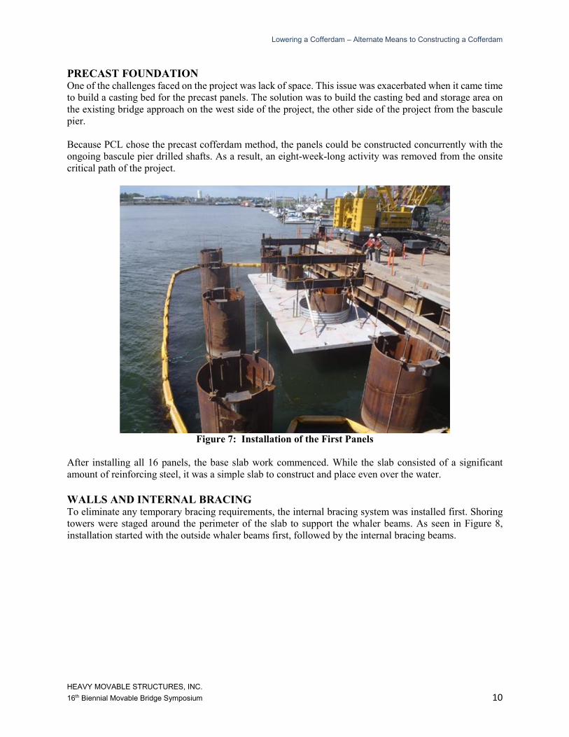
PRECAST FOUNDATION
One of the challenges faced on the project was lack of space. This issue was exacerbated when it came time
to build a casting bed for the precast panels. The solution was to build the casting bed and storage area on
the existing bridge approach on the west side of the project, the other side of the project from the bascule
pier.
Because PCL chose the precast cofferdam method, the panels could be constructed concurrently with the
ongoing bascule pier drilled shafts. As a result, an eight-week-long activity was removed from the onsite
critical path of the project.
Figure 7: Installation of the First Panels
After installing all 16 panels, the base slab work commenced. While the slab consisted of a significant
amount of reinforcing steel, it was a simple slab to construct and place even over the water.
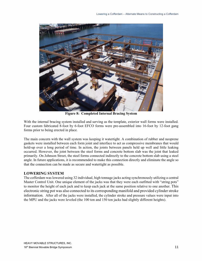
WALLS AND INTERNAL BRACING To eliminate any temporary bracing requirements, the internal bracing system was installed first. Shoring
towers were staged around the perimeter of the slab to support the whaler beams. As seen in Figure 8,
installation started with the outside whaler beams first, followed by the internal bracing beams.
Lowering a Cofferdam – Alternate Means to Constructing a Cofferdam
HEAVY MOVABLE STRUCTURES, INC.
16th Biennial Movable Bridge Symposium 11
Figure 8: Completed Internal Bracing System
With the internal bracing system installed and serving as the template, exterior wall forms were installed.
Four custom fabricated 8-foot by 6-foot EFCO forms were pre-assembled into 16-foot by 12-foot gang
forms prior to being erected in place.
The main concern with the wall system was keeping it watertight. A combination of rubber and neoprene
gaskets were installed between each form joint and interface to act as compressive membranes that would
hold-up over a long period of time. In action, the joints between panels held up well and little leaking
occurred. However, the joint between the steel forms and concrete bottom slab was the joint that leaked
primarily. On Johnson Street, the steel forms connected indirectly to the concrete bottom slab using a steel
angle. In future applications, it is recommended to make this connection directly and eliminate the angle so
that the connection can be made as secure and watertight as possible.
LOWERING SYSTEM The cofferdam was lowered using 32 individual, high tonnage jacks acting synchronously utilizing a central
Master Control Unit. One unique element of the jacks was that they were each outfitted with “string pots”
to monitor the height of each jack and to keep each jack at the same position relative to one another. This
electronic string pot was also connected to its corresponding manifold and provided cylinder stroke
information. After all of the jacks were installed, the cylinder stroke and pressure values were input into
the MPU and the jacks were leveled (the 100 ton and 150 ton jacks had slightly different heights).
Lowering a Cofferdam – Alternate Means to Constructing a Cofferdam
HEAVY MOVABLE STRUCTURES, INC.
16th Biennial Movable Bridge Symposium 12
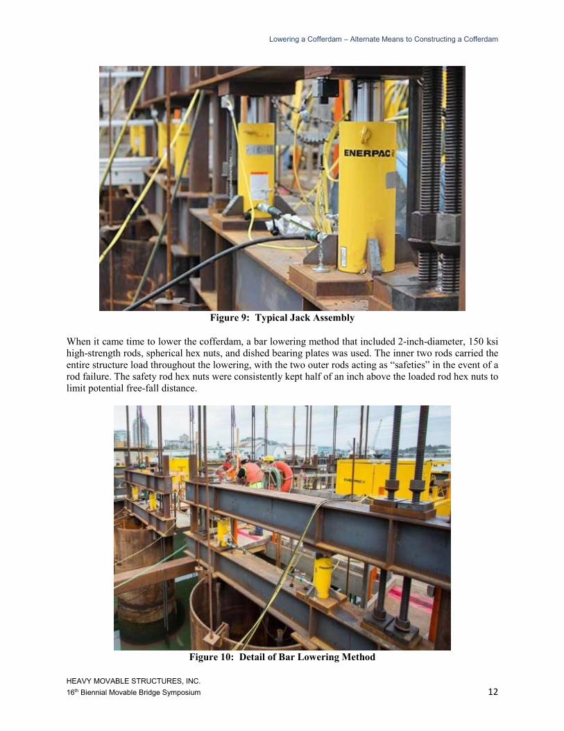
Figure 9: Typical Jack Assembly
When it came time to lower the cofferdam, a bar lowering method that included 2-inch-diameter, 150 ksi
high-strength rods, spherical hex nuts, and dished bearing plates was used. The inner two rods carried the
entire structure load throughout the lowering, with the two outer rods acting as “safeties” in the event of a
rod failure. The safety rod hex nuts were consistently kept half of an inch above the loaded rod hex nuts to
limit potential free-fall distance.
Figure 10: Detail of Bar Lowering Method
Lowering a Cofferdam – Alternate Means to Constructing a Cofferdam
HEAVY MOVABLE STRUCTURES, INC.
16th Biennial Movable Bridge Symposium 13
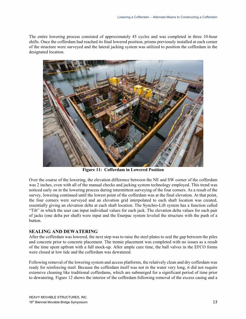
The entire lowering process consisted of approximately 45 cycles and was completed in three 10-hour
shifts. Once the cofferdam had reached its final lowered position, prisms previously installed at each corner
of the structure were surveyed and the lateral jacking system was utilized to position the cofferdam in the
designated location.
Figure 11: Cofferdam in Lowered Position
Over the course of the lowering, the elevation difference between the NE and SW corner of the cofferdam
was 2 inches, even with all of the manual checks and jacking system technology employed. This trend was
noticed early on in the lowering process during intermittent surveying of the four corners. As a result of the
survey, lowering continued until the lowest point of the cofferdam was at the final elevation. At that point,
the four corners were surveyed and an elevation grid interpolated to each shaft location was created,
essentially giving an elevation delta at each shaft location. The Synchro-Lift system has a function called
“Tilt” in which the user can input individual values for each jack. The elevation delta values for each pair
of jacks (one delta per shaft) were input and the Enerpac system leveled the structure with the push of a
button.
SEALING AND DEWATERING After the cofferdam was lowered, the next step was to raise the steel plates to seal the gap between the piles
and concrete prior to concrete placement. The tremie placement was completed with no issues as a result
of the time spent upfront with a full mock-up. After ample cure time, the ball valves in the EFCO forms
were closed at low tide and the cofferdam was dewatered.
Following removal of the lowering system and access platforms, the relatively clean and dry cofferdam was
ready for reinforcing steel. Because the cofferdam itself was not in the water very long, it did not require
extensive cleaning like traditional cofferdams, which are submerged for a significant period of time prior
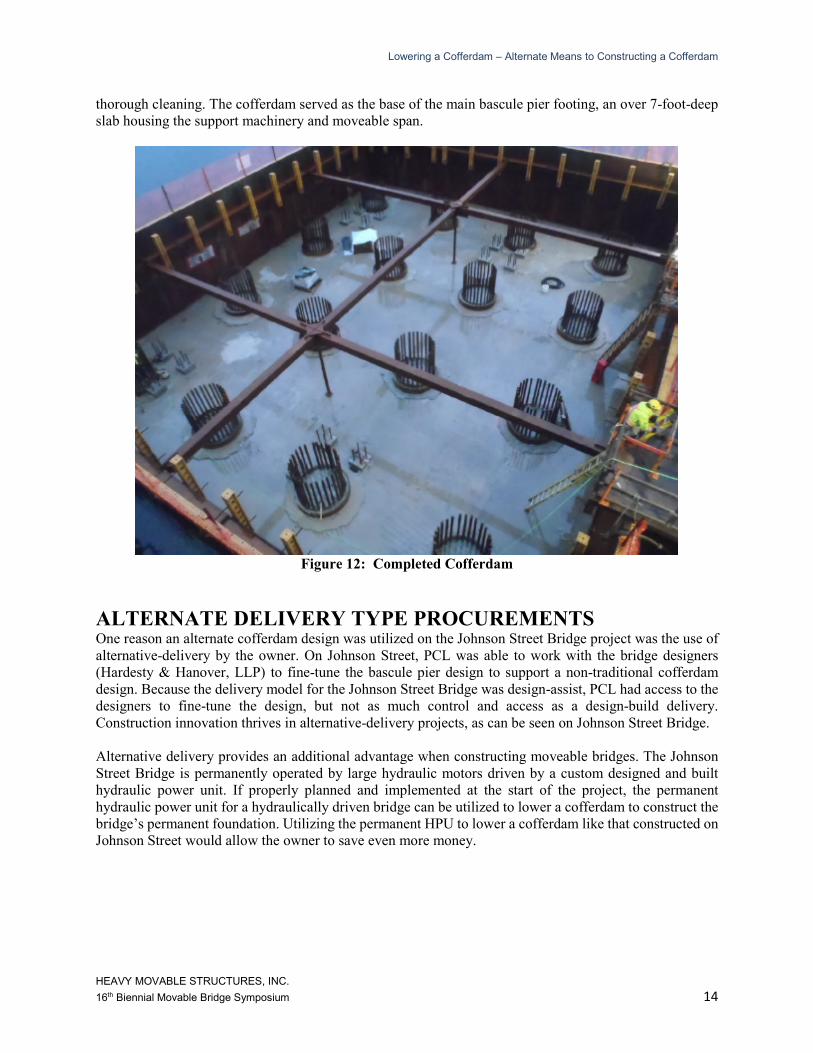
to dewatering. Figure 12 shows the interior of the cofferdam following removal of the excess casing and a
Lowering a Cofferdam – Alternate Means to Constructing a Cofferdam
HEAVY MOVABLE STRUCTURES, INC.
16th Biennial Movable Bridge Symposium 14
thorough cleaning. The cofferdam served as the base of the main bascule pier footing, an over 7-foot-deep
slab housing the support machinery and moveable span.
Figure 12: Completed Cofferdam
ALTERNATE DELIVERY TYPE PROCUREMENTS One reason an alternate cofferdam design was utilized on the Johnson Street Bridge project was the use of
alternative-delivery by the owner. On Johnson Street, PCL was able to work with the bridge designers
(Hardesty & Hanover, LLP) to fine-tune the bascule pier design to support a non-traditional cofferdam
design. Because the delivery model for the Johnson Street Bridge was design-assist, PCL had access to the
designers to fine-tune the design, but not as much control and access as a design-build delivery.
Construction innovation thrives in alternative-delivery projects, as can be seen on Johnson Street Bridge.
Alternative delivery provides an additional advantage when constructing moveable bridges. The Johnson
Street Bridge is permanently operated by large hydraulic motors driven by a custom designed and built
hydraulic power unit. If properly planned and implemented at the start of the project, the permanent
hydraulic power unit for a hydraulically driven bridge can be utilized to lower a cofferdam to construct the
bridge’s permanent foundation. Utilizing the permanent HPU to lower a cofferdam like that constructed on
Johnson Street would allow the owner to save even more money.
Lowering a Cofferdam – Alternate Means to Constructing a Cofferdam
HEAVY MOVABLE STRUCTURES, INC.
16th Biennial Movable Bridge Symposium 15
CONCLUSION There are several factors to consider when selecting the means and type of temporary structures used to
construct large marine foundations, many of them site specific. The successful use of the modular cofferdam
system on the Johnson Street Bridge demonstrated the effectiveness of float-in type cofferdam construction
for pile-caps in water where the caps are located below water, but elevated off the bottom.
REFERENCES
1. Bridge rendering (Figure 1) – MMM Group, LTD.
2. Bittner, R.B.: Deep Marine Foundations – A Perspective on the Design and Construction
of Deep Marine Foundations, Deep Foundation Institute, January 31, 2009, pp. 215-228
3. Bittner, R.B.: Float-In Installation Of A 6,000 Ton Cofferdam Over The Top Of 63 6-Ft
Diameter Pipe Piles On The Port Mann Bridge, December, 2011