Lower Wonga Solar Farm - gympie.qld.gov.au · Solar Q 233 Delaneys Creek Road ... are provided in...
26
LOWER WONGA SOLAR FARM Development Application for a Material Change of Use – Engineering Services Report || April 2017
Transcript of Lower Wonga Solar Farm - gympie.qld.gov.au · Solar Q 233 Delaneys Creek Road ... are provided in...

LOWER WONGA SOLAR FARM Development Application for a Material Change of Use – Engineering Services Report || April 2017

This document is UNCONTROLLED printed – refer to Document Management Procedure for CONTROLLED version
TMM QMS Template Reference: prj-tem-001.v1
Solar Q
Lower Wonga Solar Farm – Stage 1
Development Application – Engineering Services Report
Prepared for:
Scott Armstrong
0417 608 071 | [email protected]
Solar Q
233 Delaneys Creek Road
Delaneys Creek QLD 4514
Prepared by:
Alex Armstrong
0417 778 960 | [email protected]
Bordstrong Developments Pty Ltd
C/O: L9, 300 Ann Street
Brisbane QLD 4000
Document Ref: BI16051-ENG-REP-001
Rev Date Description Sign Off
A 06/02/2017 For Use Orig
Alex Armstrong
Check
Dave Mason
App:
Alex Armstrong
Lower Wonga Solar Farm – Stage 1
Development Application - Engineering Service Report
This document is UNCONTROLLED printed – refer to Document Management Procedure for CONTROLLED version
Printed 12/04/2017 at 12:08 i BI16051-ENG-REP-001_A
Table of Contents Executive Summary
1 Introduction ......................................................................................................................................................... 1
1.1 Purpose and Scope ...................................................................................................................................... 1
1.2 Site Description ........................................................................................................................................... 1
2 Detailed description of the Solar Farm ................................................................................................................. 2
2.1 General Parameters .................................................................................................................................... 2
2.2 Photovoltaic Solar Panel Sections ............................................................................................................... 4
2.3 Solar Panel Mounting Racks ........................................................................................................................ 4
2.4 Inverter Block Sections ............................................................................................................................... 5
2.5 LWSF Electrical Works - Internal ................................................................................................................. 6
2.6 Substation and Transmission Connection ................................................................................................... 6
2.7 Energy Storage ............................................................................................................................................ 8
2.8 Transmission and Distribution Infrastructure Management ........................................................................ 8
2.8.1 Powerlink ...................................................................................................................................................... 8
2.8.2 Energex ......................................................................................................................................................... 9
2.8.3 Ergon ............................................................................................................................................................. 9
2.9 Easement Management – During construction and Operations .................................................................. 9
3 Proposed Industrials Area .................................................................................................................................. 11
3.1 Operations and Administration Building ................................................................................................... 11
3.2 Maintenance and Storage Building ........................................................................................................... 12
3.3 Vehicle Storage ......................................................................................................................................... 12
3.4 Fuel Storage .............................................................................................................................................. 12
3.5 Site Security .............................................................................................................................................. 12
4 Animal Management ......................................................................................................................................... 12
5 Operating Hours and Workforce – Construction and Operations ....................................................................... 12
6 Operating Hours and Workforce – Construction and Operations ....................................................................... 13
7 Site Decommissioning ....................................................................................................................................... 14
8 Environmental Management – Construction and Operations ............................................................................ 15
9 Safety Management – Construction and Operations .......................................................................................... 15
10 Transport and Traffic ..................................................................................................................................... 15

Lower Wonga Solar Farm – Stage 1
Development Application - Engineering Service Report
This document is UNCONTROLLED printed – refer to Document Management Procedure for CONTROLLED version
Printed 12/04/2017 at 12:08 ii BI16051-ENG-REP-001_A
Appendix A Attachment 1
Lower Wonga Solar Farm Connection Point and Regional Renewable Benefits
Appendix B Attachment 2
Indicative Panel Spacing
Appendix C Attachment 3
Pre-Design Site Assessment Parameters
Figure 1 Proposed Land Development Area
Figure 2 PV Overlay
Figure 3 Racking and Post Installation Method utilised by UGL Limited
Figure 4 Solar PV Panels over grassed and undulating land
Figure 5 An 830 to 3,500 kVA Inverter and Transformer
Figure 6 Substation Location Options
Figure 7 Typical 132kV Transformer Bay Configuration
Figure 8 Typical structures on the Lower Wonga site
Figure 9 Existing transmission lines on the LWSF site
Figure 10 Alternative Locations for the Industrial Area
Figure 11 Indicative Range of Ground Maintenance and Cleaning Options
Table 1 Land Descriptions and Areas
Table 2 Easements located on the LWSF site

Lower Wonga Solar Farm – Stage 1
Development Application - Engineering Service Report
This document is UNCONTROLLED printed – refer to Document Management Procedure for CONTROLLED version
Printed on 12/04/2017 at 12:08 Page 1 of 15 BI16051-ENG-REP-001_A
1 Introduction
1.1 Purpose and Scope
The Engineering Services Report has been prepared in support of a Material Change of Use (MCU) Application
for the proposed Lower Wonga Solar Farm (LWSF) located at Lower Wonga approximately 20km west of
Gympie in South-east Queensland. The report has been prepared by Bordstrong Developments Pty Ltd (BSD) -
the owner, developer and applicant for the proposed solar farm.
BSD proposes to construct and operate the LWSF with a nominal capacity of 350 megawatts of alternating
current (MWac) which will be connected directly to the National Electricity Grid at the Powerlink Woolooga
Substation. The Solar Farm will be constructed on land contiguous with the Woolooga Substation and will feed
into the National Electricity Grid through either a 275kV or a 132kV connection. The LWSF will contain an
Ancillary Equipment and Maintenance Support facility which will service the photovoltaic panels and supports
and will include a 33kV customer connection substation, a maintenance shed and a storage facility.
The LWSF will include internal roads, an access from both the Wide Bay Highway and the Gympie Woolooga
Road as well as a car and bus park.
The purpose of the Engineering Services Report is to identify, address and document engineering issues
associated with the construction and operation of the proposed LWSF and will demonstrate how the proposed
development will meet the engineering objectives and outcomes outlined in the Gympie Regional Council
Planning Scheme 2013 version 1.2.
1.2 Site Description
The proposed LWSF site is located on eight parcels of adjoining land at Lower Wonga. Three of the parcels –
Lot 235 on LX2129, Lot 236 and Lot 237 on LX496 – have frontage on the Wide Bay Highway, two of the parcels
– Lot 243 and Lot 244 on LX496 - have frontage on Phillips Road whilst three smaller parcels - Lot 1, Lot 2 and
Lot 3 on RP183439 - have frontage on the Gympie Woolooga Road . The total area of the site is approximately
572 hectares as shown on Figure 1.
The site is well drained with two waterways Black Creek and Spring Creek flowing towards the east. Although
the site is drained by the creeks, the creeks do not have defined beds or banks on the proposed site. A number
of small farm dams have been constructed on the creeks for stock watering.
The relief is described as undulating land, the highest point on the north-west corner has an elevation of
approximately 100mRL whilst the lowest point in the south-east has an elevation of approximately 70mRL.
The maximum slope is about 10% and most of the land has a slope of less than 5%. A detailed aerial survey of
the site has been undertaken.
The surrounding land use is a mix of cattle breeding and fattening and industrial use with power transmission
easements over the proposed site and the adjoining Powerlink Woolooga Substation dominating the
landscape.
The land was cleared of native vegetation possibly one hundred years ago. The current vegetation supports
cattle grazing and is primarily comprised of introduced pasture species such as Rhodes Grass and Couch Grass.
There is a small number of old Eucalypt trees remaining on the site providing shade for cattle and a source of
fence posts.
There are no buildings on Lot 235, Lot 236 or Lot 237 on the northern side of the project area. The remaining
five parcels each have a residence and small farm buildings.
The Wide Bay Highway and the Gympie Woolooga Road are State-controlled roads with a sealed two lane
surface whilst Phillips Road is a Gympie Regional Council road and has a single lane sealed surface.

Lower Wonga Solar Farm – Stage 1
Development Application - Engineering Service Report
This document is UNCONTROLLED printed – refer to Document Management Procedure for CONTROLLED version
Printed on 12/04/2017 at 12:08 Page 2 of 15 BI16051-ENG-REP-001_A
2 Detailed description of the Solar Farm
2.1 General Parameters
BSD seeking Development Approval to construct and operate a utility scale photovoltaic (PV) power
generation plant as described above. Figure 1 and Table 1 indicate the location and land parcels incorporated
in the development.
Figure 1: Proposed Land Development Area
Table 1: Land Descriptions and Areas
Lot/Plan Land - Hectare
235LX2129 85.6
236LX496 97.2
237LX496 97.1
244LX496 97.3
243LX496 97.0
1RP183439 20.0
2RP183439 20.0
3RP183439 57.8
TOTAL 572

Lower Wonga Solar Farm – Stage 1
Development Application - Engineering Service Report
This document is UNCONTROLLED printed – refer to Document Management Procedure for CONTROLLED version
Printed on 12/04/2017 at 12:08 Page 3 of 15 BI16051-ENG-REP-001_A
In addition to the eight parcels of land comprising 572ha currently under contract for the proposed LWSF, land
owned by Powerlink surrounding the Woolooga Substation may be incorporated into various aspects of the
LWSF subject to final approval by Powerlink.
The total land area of about 572ha will have up to 240ha of PV panel coverage. The site will include buildings,
access roadways, parking and laydown areas. Vegetative screening will be established along the Wide Bay
Highway frontage. The total operational land coverage will be up to 250ha. The balance of the land will be the
greenscape between panel racks, transmission easement areas, drainage lines and open space.
The initial development area and preliminary design overlay shown in Figure 2 will be optimised during the
final design phase to ensure efficiency and standards are achieved prior to tendering. The expected final
design of the LWSF will have the nominal capacity of 350MW and approximately two million photovoltaic (PV)
panels. The panel clusters will be connected to about 140 inverters with a capacity of 2.5MW. The inverters
are concrete pad mounted and connected to the LWSF substation by local 33kV transmission lines mounted
overhead or buried underground. The network connection capacity is expected to be in the order of
350MW(ac). The network connection voltage will be either a 33kV transformer ended feeder or a
132kV/275kV landing beam connection and is subject to the Powerlink connection delivery scope.
Figure 2: Site Layout (draft and prior to final design)
The LWSF utilises land contiguous with the Woolooga Substation and will establish a Renewable Energy Zone
in the Gympie region. The proposed LWSF land given its close proximity to a major substation carries a number
of high voltage transmission and distribution power lines and the aligning easements. The transmission lines
are high voltage systems of both 275kV and 132kV and supply electrical energy to the Kilkivan, Gympie and
Sunshine Coast Regions and connection into the North Brisbane region. These regions have the highest total
electricity demand in Queensland and the average demand is forecast to be approximately 22,475,000 MWh
for the financial year 2017/18. The LWSF at full capacity is expected to produce approximately 735,840MWh/
year or 3.3% of regional demand. Additional detail is available on Attachment 1.

Lower Wonga Solar Farm – Stage 1
Development Application - Engineering Service Report
This document is UNCONTROLLED printed – refer to Document Management Procedure for CONTROLLED version
Printed on 12/04/2017 at 12:08 Page 4 of 15 BI16051-ENG-REP-001_A
The LWSF will utilise the easements for underground works and internal site roads and tracks. The easements
will be kept clear ensuring that the LWSF meets the access requirements of both Energex and Powerlink. The
LWSF development is a natural fit for the land already the subject of transmission line easements, electrical
infrastructure and the Woolooga Substation.
The works on site in both the construction and operations phases will be conducted in compliance with the
relevant codes, standards and legislation.
The project will incorporate the following structures and requirements:
• Photovoltaic solar panels
• Solar panel framing and support racks
• Inverter transformers
• Internal maintenance roads and tracks
• Underground and overhead high voltage conductors
• High voltage substation
• Operations and administration building
• Maintenance and storage building
• Vehicle car park
• Road access
2.2 Photovoltaic Solar Panel Sections
The LWSF will maximise the utilisation of the land adjoining the Woolooga Substation, the land not included in
the transmission powerline easements and the disused land within the Woolooga Substation subject to
Powerlink approval. The design will allow for panel frame spacing between sections from around 2m to 4m
and will be dependent on topography, shadowing, and maintenance allowances. The solar panel land coverage
will be up to 240 ha and the number of panels utilised will vary around efficiency and manufacturers panel
dimensions. As an indicative example the site could carry about two million 345 watt panels. Some design
considerations are provided in Attachment 2 and preliminary design parameters are provided in Attachment 3.
2.3 Solar Panel Mounting Racks
The solar industry is continuing to evolve and innovate to meet high levels of engineering standards and
striving to reduce the significant installation costs. Figure 3 shows solar panels mounted on off-ground racks
which is indicative of the design methods to be utilised at the LWSF. During detailed design an assessment of
fixed mounting as in Figure 3, single axis and double axis mounting will be assessed for economic benefits.
Another area of innovation and optimisation is the post installation techniques, the construction is likely to use
a range of post installation methods such as pile driven, screwed or concreted. The final installation method
will be subject to final engineering supported with detailed geotechnical studies. The Geotechnical Report is
included in the DA submission as Appendix A to the Town Planning Report.
The construction of the racks is a significant component of the capital costs and installation efficiencies are
continuing to evolve to deliver improvements in engineering and costs. As a result of continued innovation,
the mounting racks will be prefabricated off-site and transported to site for assembly. The LWSF will utilise the
best available installation methods that meet engineering requirements and deliver installation efficiencies.
Figure 3 shows a steel post and pile driven installation method and the preparation area for an inverter pad
and connection. Figure 4 is indicative of a panel cleaning method and typical panel layouts.

Lower Wonga Solar Farm – Stage 1
Development Application - Engineering Service Report
This document is UNCONTROLLED printed – refer to Document Management Procedure for CONTROLLED version
Printed on 12/04/2017 at 12:08 Page 5 of 15 BI16051-ENG-REP-001_A
Figure 3: Racking and post installation method utilised by UGL Limited
Figure 4: Solar PV panels over grassed and undulating land
2.4 Inverter Block Sections
PV panels produce energy at a Direct Current (dc) voltage and require the conversion to Alternating Current
(ac) to allow connection to the transmission grid. The panel blocks will be connected to the inverter for

Lower Wonga Solar Farm – Stage 1
Development Application - Engineering Service Report
This document is UNCONTROLLED printed – refer to Document Management Procedure for CONTROLLED version
Printed on 12/04/2017 at 12:08 Page 6 of 15 BI16051-ENG-REP-001_A
conversion to ac, and these inverters could vary in size and are continuing to grow in capability as solar farm
scales increase. The latest designs utilise the 2.5 to 3.5 Mega Volt Amperes (MVA) inverter either in a single
arrangement or double (5.0MVA) back-to-back arrangement. The number of inverters required for the LWSF
will be up to 150 inverters based on a single arrangement design. A 2.5MVA inverter will collect the energy
from around 9,500 panels and a 5MVA inverter will double that number of panels.
The inverters will be located around the site connected to PV sections and mounted on ground level precast
concrete pads. The output of the inverters is 33kV. The dimensions of the Ingecon Sun Power Station 3.5MVA
plant in Figure 5 are 13.5m by 5m by 2.9m (0.3m above the ground).
Figure 5: An 830 to 3,500 kVA Inverter and Transformer
2.5 LWSF Electrical Works - Internal
The internal high voltage network is expected to be a 33kV circuit and will be above ground or underground or
a combination of both subject to the final design, energy transfer efficiency and capital cost. There will be
approximately 16km of high voltage network on the site.
Consultation is continuing with Ergon Energy, Energex and Powerlink to plan the relocation and management
of the distribution network currently crossing the site. The aim of the consultation is to improve the efficiency
of solar generation. Both the overhead and underground network will be designed to comply with the
engineering and regulatory standards to accommodate the establishment of the LWSF whilst meeting the
needs of Powerlink, Ergon Energy and Energex.
2.6 Substation and Transmission Connection
The current design is based on a 33kV to 132kV or 275kV transfer requirement for connection to the Powerlink
Woolooga Substation. The final connection voltage of 33kV, 132kV, or 275kV will be finalised during the LWSF
final design and the formal Connection Application process with Powerlink. Engineering discussions in
response to the formal Network Connection Enquiry are developing the option for the LWSF to connect at
33kV, 132kV or 275kV. The discussions will determine the location of the substation either on LWSF land or on
the Woolooga Substation land if the substation is owned by Powerlink.
The benefit to the LWSF of Powerlink building, owning, operating and maintaining the substation on Powerlink
land is that this location will allow for an increased PV development or increasing the battery storage
footprint.

Lower Wonga Solar Farm – Stage 1
Development Application - Engineering Service Report
This document is UNCONTROLLED printed – refer to Document Management Procedure for CONTROLLED version
Printed on 12/04/2017 at 12:08 Page 7 of 15 BI16051-ENG-REP-001_A
Figure 6 indicates the alternative sites for the location of the substation either on Powerlink land or on the
LWSF land. The final substation location will be based on both a technical and commercial assessment at the
time of signing the Generation Connection and Access Agreement (GCAA). Figure 7 also provides alternative
locations for possible connection at the Woolooga Substation, technical optimisation discussions are
progressing with Powerlink.
Figure 6: Substation location options
The Figure 7 below is the typical configuration of a 132kV transformer, Circuit Breaker and Isolation bay.
Figure 7: Typical 132kV Transformer Bay configuration

Lower Wonga Solar Farm – Stage 1
Development Application - Engineering Service Report
This document is UNCONTROLLED printed – refer to Document Management Procedure for CONTROLLED version
Printed on 12/04/2017 at 12:08 Page 8 of 15 BI16051-ENG-REP-001_A
Powerlink have indicated that the structural heights of high voltage landing beams will be in the order of 15m
and typically below the 44m heights of transmission lattice towers that populate the site. The site currently
accommodates 6 x 132kV double circuit steel lattice towers for the Gympie feeder and 11 x 275kV single
circuit steel lattice for both the Palmwoods and Brisbane feeders as shown in Figure 8.
Figure 8: Typical structures on the Lower Wonga site
2.7 Energy Storage
Although not included in the LWSF Stage 1 Development Application for a Material Change of Use, battery
storage is planned for the future development of the Renewable Energy Hub at Lower Wonga.
The electrical energy market is continuing to evolve and as renewable energy generation increases, energy
supply and energy storage will become integral components of the energy market. Energy storage at this point
is not economic, but prices are falling at an accelerating rate. Battery storage will provide both energy and
ancillary services for the electricity market and provide significant support to the Gympie and South Eastern
Queensland regions.
The future battery installation will be located adjacent to the Woolooga substation and any noise produced
will be within the envelope of the existing Static Variable Compensator (SVC) at the substation. An assessment
will be conducted during the design phase conducting further assessment of energy storage. This would lead
to an allocation of land in the future development footprint followed by a Development Application seeking
approval for a Material Change of Use for Energy Storage.
2.8 Transmission and Distribution Infrastructure Management
The existing transmission lines across the proposed LWSF site are shown in Figure 9 and the transmission line
easements are identified with areas and provided in Table 2.
2.8.1 Powerlink
Powerlink will be the connecting party as the incumbent Transmission Network Service Provider (TNSP) and
owner of the Woolooga Substation. The LWSF has completed the Connection Enquiry stage and will ensure

Lower Wonga Solar Farm – Stage 1
Development Application - Engineering Service Report
This document is UNCONTROLLED printed – refer to Document Management Procedure for CONTROLLED version
Printed on 12/04/2017 at 12:08 Page 9 of 15 BI16051-ENG-REP-001_A
compliance with Powerlink policies on issues such as building near easements, maintenance of clear ways,
efficient use of easements for servicing tracks and other activities as agreed between the parties. Clear
communications will be maintained at all times with Powerlink.
2.8.2 Energex
As for Powerlink, Energex has been involved prior to design and development to incorporate local distribution
issues into the pre-design and development phases. This will continue during construction and ongoing
operations. Clear communications will be maintained regarding building near easements, maintenance of clear
ways, efficient use of easements for such requirements as servicing tracks and other activities as agreed
between the parties.
2.8.3 Ergon
Engagement with Ergon’s Town Planning Department has been initiated to reach agreement on the way
forward to relocate transmission lines. The LWSF will work with Ergon to minimise impacts on customers
during the period of these changes. Clear communication regarding building near residual and new
easements, maintenance of clear ways, efficient use of easements for such requirements as servicing tracks
and other activities as agreed between the parties. The blue lines on the following picture are the Ergon high
voltage powerlines.
Figure 9: Existing transmission lines on the LWSF site
2.9 Easement Management – During construction and Operations • Safety - Conductor clearances will be maintained in accordance with:
- Electrical Safety Act 2002 (or latest revision)
- Electrical Safety Regulations 2013 (or latest revision)
- Terms and Conditions as specified on the Registered Easements
- Powerlink Management of Easement documents
• The easement will always be kept clear for DNSP and TNSP to access their respective networks.
• The LWSF in consultation and agreement with Powerlink, Energex and Ergon:

Lower Wonga Solar Farm – Stage 1
Development Application - Engineering Service Report
This document is UNCONTROLLED printed – refer to Document Management Procedure for CONTROLLED version
Printed on 12/04/2017 at 12:08 Page 10 of 15 BI16051-ENG-REP-001_A
- will be built up to the easements boundaries
- The easements may be used as internal maintenance tracks
- Internal networks and services may need to cross the easements to link the solar farm
- The easement areas will be maintained to ensure fire, weed and vermin risks are managed.
Table 2: Easements located on the LWSF site
Lot/PR Area - ha Easements No. Area - ha Easements No. Area - ha Easements No. Area - ha Net of Easements - ha
BRP186088 7.2 ARP186087 2.4
CRP186089 4.4 JSP218491 2.4
CLX2224 0.4 KSP218491 3.0
DLX2224 1.6
LSP218491 3.0
AAP21751 3.0
ARP180948 6.9
BRP180948 7.3
ARP125970 2.5
BRP138693 2.4
CRP183439
DRP183439
BRP189162 1.8 ERP183439
ARP189162 0.3
Total (ha) 571.9 41.8 14.0 516.1
3RP183439 57.8
243LX496
244LX496 97.3
97.0
1RP183439 20.0
2RP183439 20.0
Powerlink
BRP138692 7.2
235LX2129 85.6
236LX496 97.2
237LX496 97.1
Energex Ergon
69.2
92.2
83.9
83.1
92.1
20.0
20.0
55.7

Lower Wonga Solar Farm – Stage 1
Development Application - Engineering Service Report
This document is UNCONTROLLED printed – refer to Document Management Procedure for CONTROLLED version
Printed on 12/04/2017 at 12:08 Page 11 of 15 BI16051-ENG-REP-001_A
3 Proposed Industrials Area
As indicated above the LWSF is currently in the preliminary design phase. If Development Approval is obtained,
the preliminary design will be reviewed and a detailed design will be prepared for tendering and construction
purposes. The preliminary design shows two alternative locations for the industrial area. The final location of
the industrial area will depend on the layout of PV sections, the final location of the LWSF substation and
various maintenance distances to the outlying PV sections as well as other factors. The alternate locations are
shown on Figure 10.
Figure 10: Alternative Locations for the Industrial Area
3.1 Operations and Administration Building
The Operations and Administration building will be a single storey construction clad, brick or block
construction with a pitched or skillion roof. The style will align to the Woolooga Substation and other
structures in the area and have a floor area of around 300m2. The building will accommodate onsite
administration and management facilities, technical monitoring of the site and solar energy production and
analysis. Information gathered will be utilised for the purposes of determining operations and maintenance
activities. It is expected that there will be four to six personal requiring office accommodation, and include
showers and toilet amenities and first aid areas.
The general layout will meet local building requirements and will include:
• Reception area
• Offices
• Open plan work stations
• Comms/Data room
• Site and Plant monitoring area
• Meeting rooms
• First aid facilities

Lower Wonga Solar Farm – Stage 1
Development Application - Engineering Service Report
This document is UNCONTROLLED printed – refer to Document Management Procedure for CONTROLLED version
Printed on 12/04/2017 at 12:08 Page 12 of 15 BI16051-ENG-REP-001_A
• Lunch and kitchen facilities
• Shower and Toilet facilities (Male and Female)
• Change rooms and lockers
• Visitor (5 bays) and employee parking area (8 bays)
3.2 Maintenance and Storage Building
The LWSF will include an ability to conduct onsite repairs and maintenance activities. This will allow the repair
of solar farm plant and servicing vehicles and machines. The site will carry sufficient spares, maintenance
consumables and tools and maintenance equipment to ensure the solar farm land is maintained and
operations and availability targets are achieved.
The building is expected to be a portal frame steel shed with a combination of closed and open bays with a
heavy duty concrete slab floor allowing for heavy vehicle, forklift and crane use. The build specifications are
expected to be an area of 800m2 with the eaves of sufficient height for efficient use of cranes and forklifts at
6m and 8.5m at the ridgeline.
Site visitors and employees will enter and operate from the Operations and Administration building, however
deliveries may be made directly to the Maintenance and Storage building. To accommodate this activity there
will be up to four parking bays available. The building may also accommodate sensitive electronic and
computer equipment in an air conditioned storage area.
3.3 Vehicle Storage
The site will require the storage of servicing vehicles such industrial mowers, tractor slashers, small to medium
tracks and tippers, crane, forklift, fire tender, and solar panel cleaners. The shed is expected to be open bay
arrangement with an ability to add roller doors if required for security upgrades.
The building is expected to be a portal frame steel shed with a combination of closed and open bays with a
heavy duty concrete slab floor allowing for heavy vehicle, forklift and crane use. The building specifications are
expected to be an area of 800m2 with the eaves of sufficient height for efficient use of cranes and forklifts at
6m and 8.5m at the ridgeline.
3.4 Fuel Storage
The site may carry up to 10,000litres of fuel for use in maintenance vehicles. The fuel will be stored in
accordance regulatory requirements including AS1940.
3.5 Site Security
The site will be enclosed with a chain link style fence with top wire of either single or double barbed wire with
lockable gates. The site may also have additional monitoring systems installed to ensure unapproved access is
recorded.
To meet access obligations to the transmission and network easements gates will be installed either near to or
aligned with the easements.
4 Animal Management
Grazing animals, likely to be sheep or other low impact animal may be used to assist in the management of
grass. Yards will be installed to support animal management which will be undertaken in accordance with best
agricultural practice. An example of sheep being utilised for grazing within a solar farm can be seen at the UQ
Gatton Solar Farm.
5 Operating Hours and Workforce – Construction and Operations

Lower Wonga Solar Farm – Stage 1
Development Application - Engineering Service Report
This document is UNCONTROLLED printed – refer to Document Management Procedure for CONTROLLED version
Printed on 12/04/2017 at 12:08 Page 13 of 15 BI16051-ENG-REP-001_A
The construction period is estimated to be approximately 18 months in duration and a peak construction
workforce of about 450 personnel will be employed during construction. It is intended that the construction
contractor will have the flexibility to undertake activities on a 24 hour 7 day basis during the construction
period. This level of flexibility will provide improved working conditions for construction employees by
allowing rest breaks during a shift involving the laborious and monotonous fixing of about two million PV
panels to supports. Safety considerations will be the highest priority and previous international experience is
that employees must have rest breaks during shifts to mitigate safety risks. Excessive heat stress during day
shifts must also be managed effectively by scheduling exposed work to night shifts under lights.
The obvious result of restrictions on working hours is that the construction period will be prolonged
unnecessarily beyond the planned 18 month duration.
In addition to safety considerations, there is relevant legislation both at the State level and the Local level
which control working activities such as noise levels and sleep disturbance.
During operations, the scheduling of maintenance activities and emergency repairs will also require the ability
to conduct 24 hour 7 day week work cycles particularly where work activities may involve PV panels normally
operating during daylight hours. As for the construction program, the management of safety issues may
involve avoiding excessive heat and regular work breaks. During normal operations, scheduling maintenance
activities to maximise energy production will require fully flexible working hours.
6 Operating Hours and Workforce – Construction and Operations
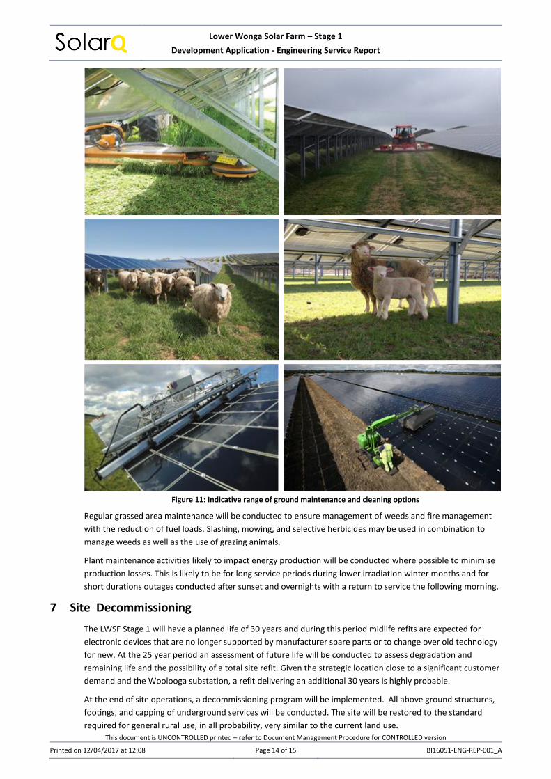
The typical maintenance activities are expected to be in the following areas some of which are shown in Figure
11:
• Groundcover management
• Water run-off management
• Weed, pest animals and vermin control
• Fire management
• Solar panel cleaning
• Solar panel replacement
• General fencing and security maintenance
• Inverter maintenance
• Substation maintenance
Lower Wonga Solar Farm – Stage 1
Development Application - Engineering Service Report
This document is UNCONTROLLED printed – refer to Document Management Procedure for CONTROLLED version
Printed on 12/04/2017 at 12:08 Page 14 of 15 BI16051-ENG-REP-001_A
Figure 11: Indicative range of ground maintenance and cleaning options
Regular grassed area maintenance will be conducted to ensure management of weeds and fire management
with the reduction of fuel loads. Slashing, mowing, and selective herbicides may be used in combination to
manage weeds as well as the use of grazing animals.
Plant maintenance activities likely to impact energy production will be conducted where possible to minimise
production losses. This is likely to be for long service periods during lower irradiation winter months and for
short durations outages conducted after sunset and overnights with a return to service the following morning.
7 Site Decommissioning
The LWSF Stage 1 will have a planned life of 30 years and during this period midlife refits are expected for
electronic devices that are no longer supported by manufacturer spare parts or to change over old technology
for new. At the 25 year period an assessment of future life will be conducted to assess degradation and
remaining life and the possibility of a total site refit. Given the strategic location close to a significant customer
demand and the Woolooga substation, a refit delivering an additional 30 years is highly probable.
At the end of site operations, a decommissioning program will be implemented. All above ground structures,
footings, and capping of underground services will be conducted. The site will be restored to the standard
required for general rural use, in all probability, very similar to the current land use.

Lower Wonga Solar Farm – Stage 1
Development Application - Engineering Service Report
This document is UNCONTROLLED printed – refer to Document Management Procedure for CONTROLLED version
Printed on 12/04/2017 at 12:08 Page 15 of 15 BI16051-ENG-REP-001_A
8 Environmental Management – Construction and Operations
Bordstrong Developments Pty Ltd (BSD) understands and is committed to the importance of maintaining a
high standard of environmental care and management in conducting all activities at the LWSF not the least
because high voltage infrastructure is involved.
From design through to supply, installation, construction and operations, BSD is committed to minimising
pollution and contributing towards a sustainable future by overseeing, managing and monitoring the activities
at the LWSF to ensure that an acceptable balance is achieved between environmental, technical, economic
and social objectives.
The combined efforts of BSD, its employees, contractors and subcontractors will ensure the effectiveness of
achieving the goal of environmental sustainability.
As a minimum, BSD will ensure that contractors who are involved in the construction and operation of the
LWSF will maintain an Environmental Management System which complies with AS/NZ ISO 14001 the key
requirements of which are:
• Set objectives and targets that define the reduction of impacts on the environment through
conducting risk assessments and hazard analyses,
• Manage operations in compliance with applicable laws, legislation, regulations, standards and codes
of practice that minimise any adverse impact on the environment,
• Conserve resources, minimising waste and seeking continual improvement of processes to protect
the environment
• Communicate with employees, clients, suppliers, contractors and the community on environmental
issues
• Provide appropriate training for awareness and education for people on environmental issues and
specifically to individuals with environmental responsibilities
• Establish Environmental Management Plans setting out the responsibilities and processes to
minimise impacts
• Ensure all work practices comply with the Environmental Management System and legislative
obligations
• Conduct monitoring and evaluation to ensure the environmental compliance and obligations are
achieved
• Require all employees and subcontractors to operate in an environmentally responsible manner and
adhere to relevant environmental requirements
• Regularly review performance, identify and implement corrective and preventative actions that
contribute to continually improving the environmental performance of operations.
9 Safety Management – Construction and Operations
Bordstrong Developments Pty Ltd will ensure that all contractors will hold accreditation to the Quality
Management System – AS/NZS ISO 9001:2008 and the Safety Management System – AS/NZS ISO 4801:2001.
10 Transport and Traffic
The TMM Group Pty Ltd have been engaged by BSD to report on Transport and Traffic issues relevant to the
construction and operation of the LWSF. The report of the Transport and Traffic Impact Assessment is
presented as Appendix 2 to the Town Planning Report. The recommendations of the Transport and Traffic
Impact Assessment will be adopted and implemented by BSD and the primary contractors on the project.

Lower Wonga Solar Farm – Stage 1
Development Application - Engineering Service Report
This document is UNCONTROLLED printed – refer to Document Management Procedure for CONTROLLED version
Printed on 12/04/2017 at 12:08 BI16051-ENG-REP-001_A
Appendix A Attachment 1 Lower Wonga Solar Farm connection point and regional renewable benefits

Lower Wonga Solar Farm – Stage 1
Development Application - Engineering Service Report
This document is UNCONTROLLED printed – refer to Document Management Procedure for CONTROLLED version
Printed on 12/04/2017 at 12:08 BI16051-ENG-REP-001_A
Lower Wonga Solar Farm & Energy Storage Connection Point
(735,480 MWh/an# or 3.3% of regional demand)
1,268,000 MWh/an*
17,804,000 MWh/an*
3,403,000 MWh/an*
* Powerlink 2016 Planning Report - 2017/18 forecast# Forecast at Maximum Site Capacity, does not include Charge/Discharge Cycling Energy
Total Regional Demand22,475,000 MWh/an*2,566 MW(average)
4,689 MW (peak)
Lower Wonga Solar Farm – Stage 1
Development Application - Engineering Service Report
This document is UNCONTROLLED printed – refer to Document Management Procedure for CONTROLLED version
Printed on 12/04/2017 at 12:08 BI16051-ENG-REP-001_A
Appendix B Attachment 2 Indicative Panel Spacing

Lower Wonga Solar Farm – Stage 1
Development Application - Engineering Service Report
This document is UNCONTROLLED printed – refer to Document Management Procedure for CONTROLLED version
Printed on 12/04/2017 at 12:08 BI16051-ENG-REP-001_A
Preliminary Design – Lower Wonga Solar Farm – Stage 1
2 x Portrait Layout 20 deg
Spacing Centre to Centre Between Panels
5.9 m 2.24 m
1.84 1.84 m - Either Side of Centre
8 7 6 5 4 3 2 1 m
High - Summer Energy
20 Deg
3.91 1.34
0.50
3.68
1.84
Nominal Design Detail: 1. Portrait Design x 2 panels 2. Panel size – 1.956m x 0.992m 3. Panel angle 200 & North facing 4. Leading edge height off ground 0.5m 5. Spacing centre to centre – 5.9m

Lower Wonga Solar Farm – Stage 1
Development Application - Engineering Service Report
This document is UNCONTROLLED printed – refer to Document Management Procedure for CONTROLLED version
Printed on 12/04/2017 at 12:08 BI16051-ENG-REP-001_A
Appendix C Attachment 3 Pre-design Site Assessment Parameters

Lower Wonga Solar Farm – Stage 1
Development Application - Engineering Service Report
This document is UNCONTROLLED printed – refer to Document Management Procedure for CONTROLLED version
Printed on 12/04/2017 at 12:08 BI16051-ENG-REP-001_A
Jinko Panels - JKM 345M-72
Spacing Rack - Centre to Centre m 8.00 6.48 5.91
Spacing Between Racks - Panel to Panel m 4.32 2.80 2.24
Project Size MW(ac) 270 334 365 Energy pre inversion MW(dc) 367 454 497
Solar Panels (345W) No. 1,064,880 1,315,440 1,440,720
Box No. 40,957 50,594 55,412
40' Containers: No. 1,707 2,108 2,309
Deliveries "B Double" No. 853 1,054 1,154
Blocks No. 108 108 108
Block Coverage Ha 434 434 434
Panel Land coverage (grass under panels) Ha 194 240 263
Racks (Rack = 2xPortrait x 29 PV Panels) No. 18,360 22,680 24,840
Posts per Rack No. 8 8 8
Posts - Racking No. 145,873 180,196 197,357
Racking lengths (2 x Portrait Design) km 528 652 715
Steel/Aluminium Weight t 21,754 26,873 29,432
Post and Racking Deliveries No. 483 597 654
Roads/tracks km 26 26 26
ha 7.9 7.9 7.9
All Weather Roads (#% of total tracks) km 5.3 5.3 5.3
Gravel/Roadbase required m3 4,768 4,768 4,768
Gravel Deliveries (Truck and Dog) No. 220 220 220
Fencing (3m including 3 x Barbed Wire) km 11 11 11
Inverter/Transformers (2.5MVA) No. 108 133 146
Inverters (on concrete pads) ha 0.49 0.61 0.67
Inverter & Pad Deliveries No. 81 100 110
33kV network km 22 27 29
t 104 128 140
Cable Deliveries No. 4 4 5
Substation ha 0.9 0.9 0.9
Substation Deliveries No. 6 6 6
Operations and Administration Building ha 0.03 0.03 0.03
Workshops & Storage ha 0.08 0.08 0.08
Vehicle storage ha 0.08 0.08 0.08
Deliveries - Building Materials No. 20 20 20
Car Park ha 0.9 0.9 0.9
Volume m3 3,600 3,600 3,600
Concrete Deliveries No. 166 166 166
Land Covered (µ 0.0) ha 10.4 10.5 10.6
Panels above grassed areas (>µ 0.0) ha 194 240 263

Lower Wonga Solar Farm – Stage 1
Development Application - Engineering Service Report
This document is UNCONTROLLED printed – refer to Document Management Procedure for CONTROLLED version
Printed on 12/04/2017 at 12:08 BI16051-ENG-REP-001_A
Land area on title/s ha 572 572 572
Balance of Land not under equipment ha 561 561 561
Total Deliveries No. 1,834 2,168 2,335
Heavy lifts No. 3 4 4
Coverage 2% 2% 2%
Open Space 98% 98% 98%
Capacity Factor % 25% 24% 23%
Production MWh/an 591,596 701,563 736,363


![Zü]lman OCEAN NÉURUM —MOUNT DELANEY 3137109 Somerset ... · Zü]lman OCEAN NÉURUM —MOUNT DELANEY 3137109 Somerset Regional Council Mount Mee DELANEYS CREEK 3137113 Mount Mee](https://static.fdocuments.in/doc/165x107/61108a42624f141ee2048aa1/zlman-ocean-nurum-amount-delaney-3137109-somerset-zlman-ocean-nurum.jpg)