Low voltage regulation system - A. Eberle€¦ · · 2016-06-22The low voltage regulation system...
8
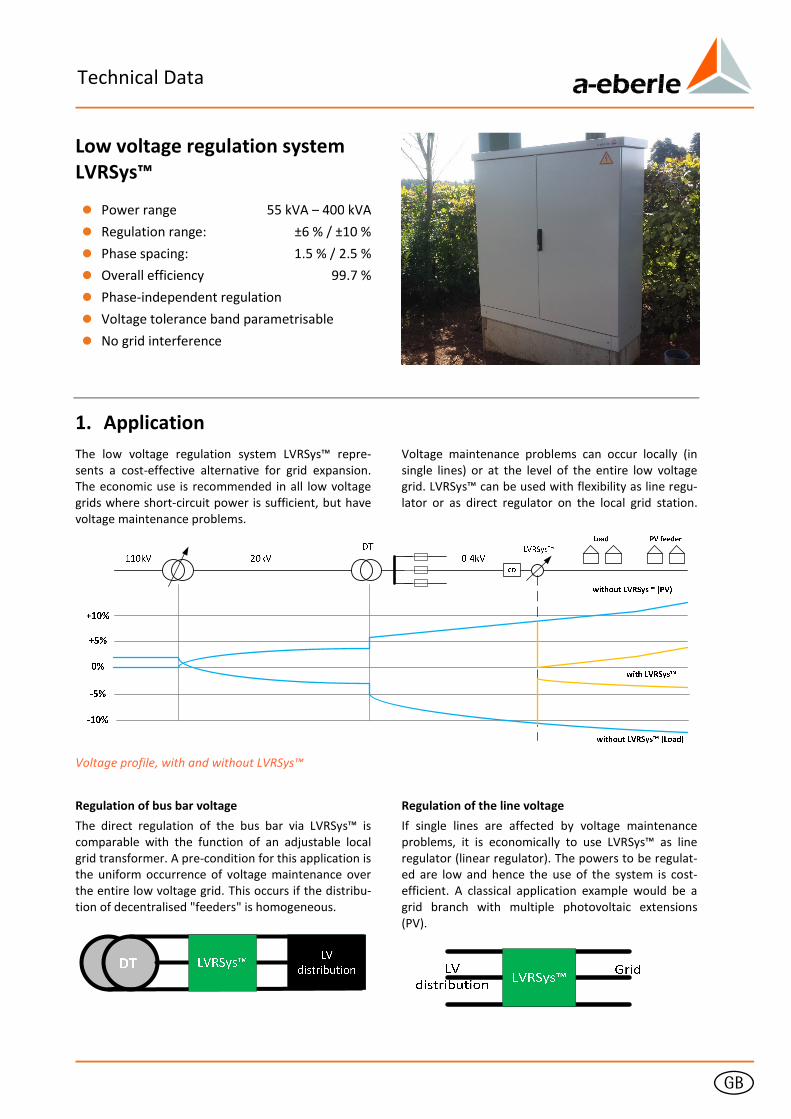
g Technical Data Low voltage regulation system LVRSys™ 0 Power range 55 kVA – 400 kVA 0 Regulation range: ±6 % / ±10 % 0 Phase spacing: 1.5 % / 2.5 % 0 Overall efficiency 99.7 % 0 Phase-independent regulation 0 Voltage tolerance band parametrisable 0 No grid interference 1. Application The low voltage regulation system LVRSys™ repre- sents a cost-effective alternative for grid expansion. The economic use is recommended in all low voltage grids where short-circuit power is sufficient, but have voltage maintenance problems. Voltage maintenance problems can occur locally (in single lines) or at the level of the entire low voltage grid. LVRSys™ can be used with flexibility as line regu- lator or as direct regulator on the local grid station. Voltage profile, with and without LVRSys™ Regulation of bus bar voltage The direct regulation of the bus bar via LVRSys™ is comparable with the function of an adjustable local grid transformer. A pre-condition for this application is the uniform occurrence of voltage maintenance over the entire low voltage grid. This occurs if the distribu- tion of decentralised "feeders" is homogeneous. Regulation of the line voltage If single lines are affected by voltage maintenance problems, it is economically to use LVRSys™ as line regulator (linear regulator). The powers to be regulat- ed are low and hence the use of the system is cost- efficient. A classical application example would be a grid branch with multiple photovoltaic extensions (PV).
Transcript of Low voltage regulation system - A. Eberle€¦ · · 2016-06-22The low voltage regulation system...
g
Technical Data
Low voltage regulation system
LVRSys™
0 Power range 55 kVA – 400 kVA
0 Regulation range: ±6 % / ±10 %
0 Phase spacing: 1.5 % / 2.5 %
0 Overall efficiency 99.7 %
0 Phase-independent regulation
0 Voltage tolerance band parametrisable
0 No grid interference
1. Application
The low voltage regulation system LVRSys™ repre-
sents a cost-effective alternative for grid expansion.
The economic use is recommended in all low voltage
grids where short-circuit power is sufficient, but have
voltage maintenance problems.
Voltage maintenance problems can occur locally (in
single lines) or at the level of the entire low voltage
grid. LVRSys™ can be used with flexibility as line regu-
lator or as direct regulator on the local grid station.
Voltage profile, with and without LVRSys™
Regulation of bus bar voltage
The direct regulation of the bus bar via LVRSys™ is
comparable with the function of an adjustable local
grid transformer. A pre-condition for this application is
the uniform occurrence of voltage maintenance over
the entire low voltage grid. This occurs if the distribu-
tion of decentralised "feeders" is homogeneous.
Regulation of the line voltage
If single lines are affected by voltage maintenance
problems, it is economically to use LVRSys™ as line
regulator (linear regulator). The powers to be regulat-
ed are low and hence the use of the system is cost-
efficient. A classical application example would be a
grid branch with multiple photovoltaic extensions
(PV).
Page 2
We take care of it.
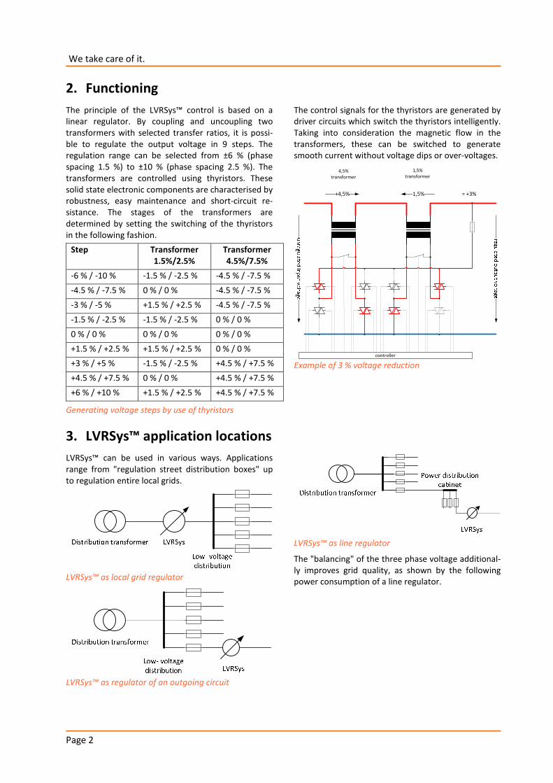
2. Functioning
The principle of the LVRSys™ control is based on a
linear regulator. By coupling and uncoupling two
transformers with selected transfer ratios, it is possi-
ble to regulate the output voltage in 9 steps. The
regulation range can be selected from ±6 % (phase
spacing 1.5 %) to ±10 % (phase spacing 2.5 %). The
transformers are controlled using thyristors. These
solid state electronic components are characterised by
robustness, easy maintenance and short-circuit re-
sistance. The stages of the transformers are
determined by setting the switching of the thyristors
in the following fashion.
Step Transformer
1.5%/2.5%
Transformer
4.5%/7.5%
-6 % / -10 % -1.5 % / -2.5 % -4.5 % / -7.5 %
-4.5 % / -7.5 % 0 % / 0 % -4.5 % / -7.5 %
-3 % / -5 % +1.5 % / +2.5 % -4.5 % / -7.5 %
-1.5 % / -2.5 % -1.5 % / -2.5 % 0 % / 0 %
0 % / 0 % 0 % / 0 % 0 % / 0 %
+1.5 % / +2.5 % +1.5 % / +2.5 % 0 % / 0 %
+3 % / +5 % -1.5 % / -2.5 % +4.5 % / +7.5 %
+4.5 % / +7.5 % 0 % / 0 % +4.5 % / +7.5 %
+6 % / +10 % +1.5 % / +2.5 % +4.5 % / +7.5 %
Generating voltage steps by use of thyristors
The control signals for the thyristors are generated by
driver circuits which switch the thyristors intelligently.
Taking into consideration the magnetic flow in the
transformers, these can be switched to generate
smooth current without voltage dips or over-voltages.
controller
4,5%
transformer
1,5%
transformer
+4,5% -1,5% = +3%
Example of 3 % voltage reduction
3. LVRSys™ application locations
LVRSys™ can be used in various ways. Applications
range from "regulation street distribution boxes" up
to regulation entire local grids.
LVRSys™ as local grid regulator
LVRSys™ as regulator of an outgoing circuit
LVRSys™ as line regulator
The "balancing" of the three phase voltage additional-
ly improves grid quality, as shown by the following
power consumption of a line regulator.
Page 3
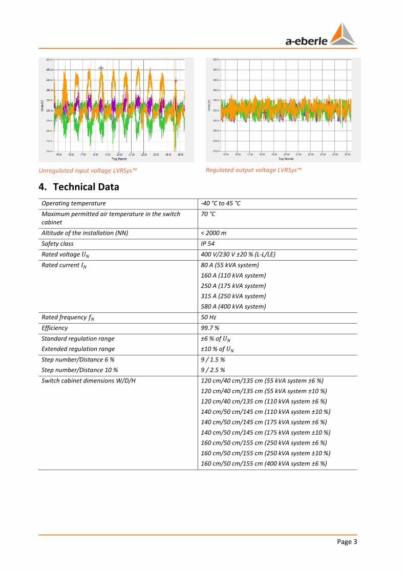
Unregulated input voltage LVRSys™
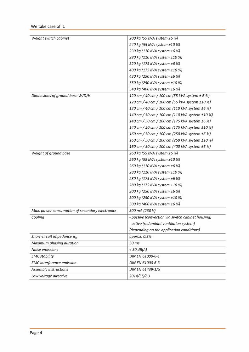
Regulated output voltage LVRSys™
4. Technical Data
Operating temperature -40 °C to 45 °C
Maximum permitted air temperature in the switch
cabinet
70 °C
Altitude of the installation (NN) < 2000 m
Safety class IP 54
Rated voltage �� 400 V/230 V ±20 % (L-L/LE)
Rated current �� 80 A (55 kVA system)
160 A (110 kVA system)
250 A (175 kVA system)
315 A (250 kVA system)
580 A (400 kVA system)
Rated frequency �� 50 Hz
Efficiency 99.7 %
Standard regulation range
Extended regulation range
±6 % of ��
±10 % of ��
Step number/Distance 6 %
Step number/Distance 10 %
9 / 1.5 %
9 / 2.5 %
Switch cabinet dimensions W/D/H
120 cm/40 cm/135 cm (55 kVA system ±6 %)
120 cm/40 cm/135 cm (55 kVA system ±10 %)
120 cm/40 cm/135 cm (110 kVA system ±6 %)
140 cm/50 cm/145 cm (110 kVA system ±10 %)
140 cm/50 cm/145 cm (175 kVA system ±6 %)
140 cm/50 cm/145 cm (175 kVA system ±10 %)
160 cm/50 cm/155 cm (250 kVA system ±6 %)
160 cm/50 cm/155 cm (250 kVA system ±10 %)
160 cm/50 cm/155 cm (400 kVA system ±6 %)
Page 4
We take care of it.
Weight switch cabinet
200 kg (55 kVA system ±6 %)
240 kg (55 kVA system ±10 %)
230 kg (110 kVA system ±6 %)
280 kg (110 kVA system ±10 %)
320 kg (175 kVA system ±6 %)
400 kg (175 kVA system ±10 %)
430 kg (250 kVA system ±6 %)
550 kg (250 kVA system ±10 %)
540 kg (400 kVA system ±6 %)
Dimensions of ground base W/D/H
120 cm / 40 cm / 100 cm (55 kVA system ± 6 %)
120 cm / 40 cm / 100 cm (55 kVA system ±10 %)
120 cm / 40 cm / 100 cm (110 kVA system ±6 %)
140 cm / 50 cm / 100 cm (110 kVA system ±10 %)
140 cm / 50 cm / 100 cm (175 kVA system ±6 %)
140 cm / 50 cm / 100 cm (175 kVA system ±10 %)
160 cm / 50 cm / 100 cm (250 kVA system ±6 %)
160 cm / 50 cm / 100 cm (250 kVA system ±10 %)
160 cm / 50 cm / 100 cm (400 kVA system ±6 %)
Weight of ground base
260 kg (55 kVA system ±6 %)
260 kg (55 kVA system ±10 %)
260 kg (110 kVA system ±6 %)
280 kg (110 kVA system ±10 %)
280 kg (175 kVA system ±6 %)
280 kg (175 kVA system ±10 %)
300 kg (250 kVA system ±6 %)
300 kg (250 kVA system ±10 %)
300 kg (400 kVA system ±6 %)
Max. power consumption of secondary electronics 300 mA (230 V)
Cooling - passive (convection via switch cabinet housing)
- active (redundant ventilation system)
(depending on the application conditions)
Short-circuit impedance �� approx. 0.3%
Maximum phasing duration 30 ms
Noise emissions < 30 dB(A)
EMC stability DIN EN 61000-6-1
EMC interference emission DIN EN 61000-6-3
Assembly instructions DIN EN 61439-1/5
Low voltage directive 2014/35/EU
Page 5
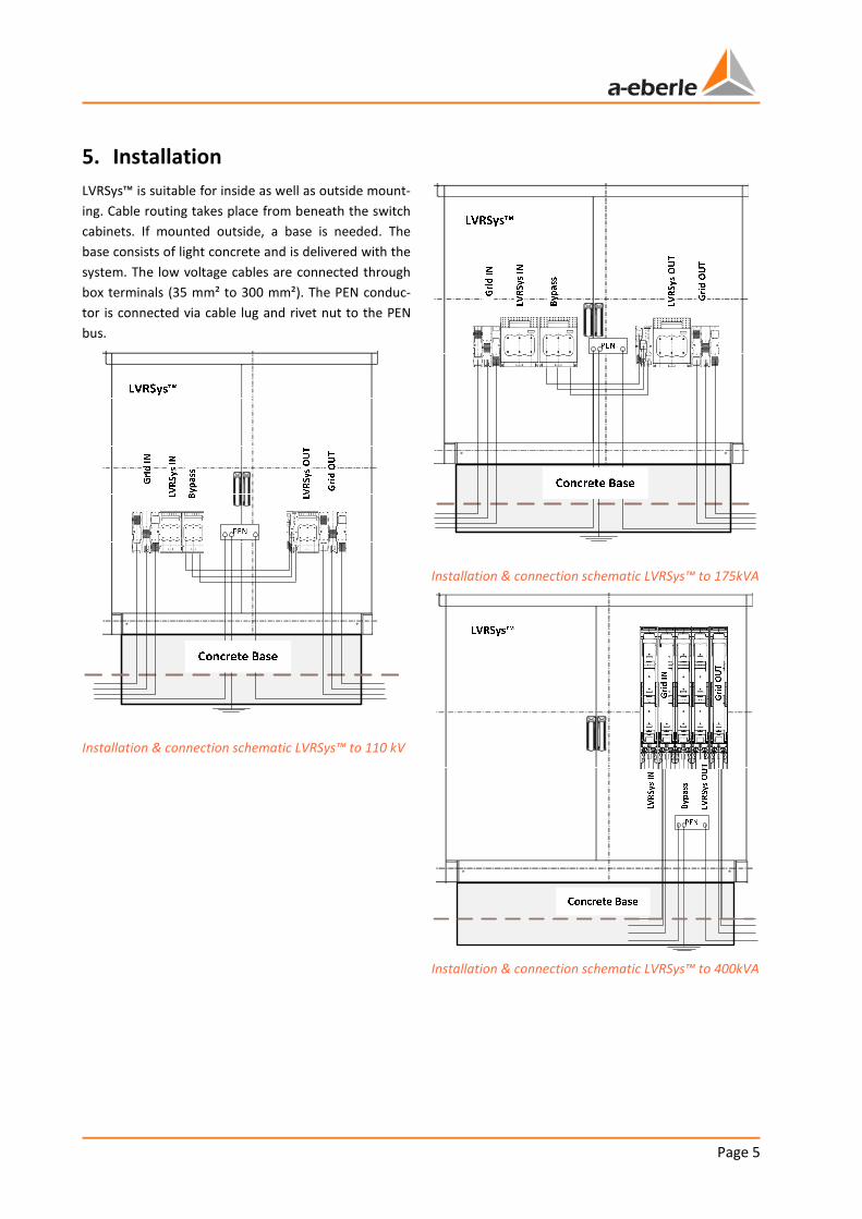
5. Installation
LVRSys™ is suitable for inside as well as outside mount-
ing. Cable routing takes place from beneath the switch
cabinets. If mounted outside, a base is needed. The
base consists of light concrete and is delivered with the
system. The low voltage cables are connected through
box terminals (35 mm² to 300 mm²). The PEN conduc-
tor is connected via cable lug and rivet nut to the PEN
bus.
Installation & connection schematic LVRSys™ to 110 kV
Installation & connection schematic LVRSys™ to 175kVA
Installation & connection schematic LVRSys™ to 400kVA
Page 6
We take care of it.
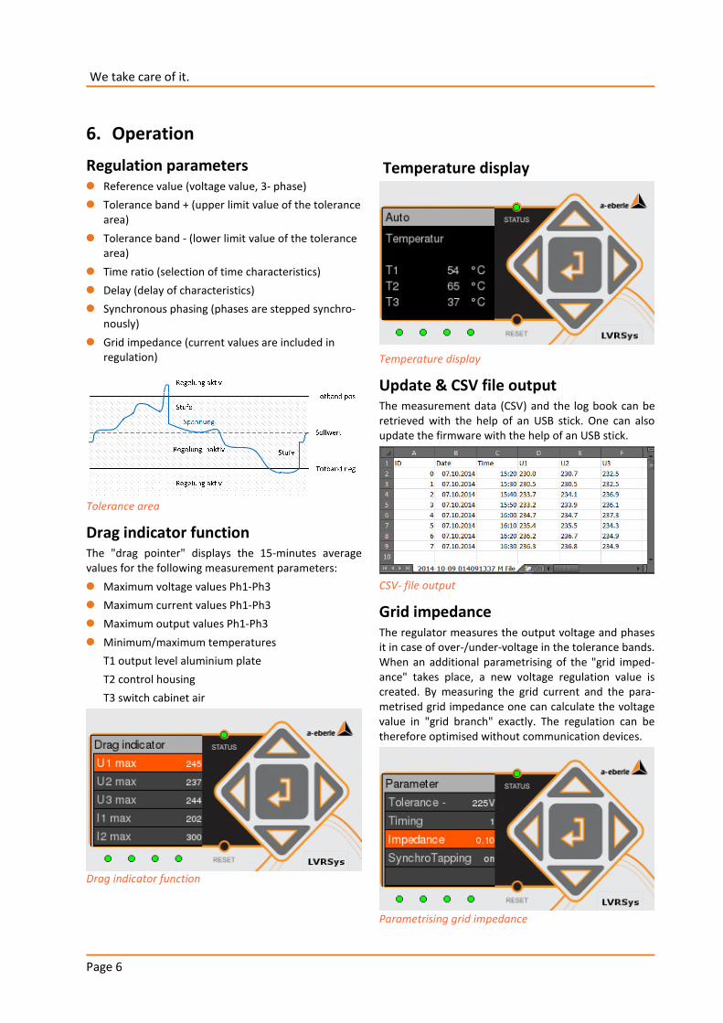
6. Operation
Regulation parameters
0 Reference value (voltage value, 3- phase)
0 Tolerance band + (upper limit value of the tolerance
area)
0 Tolerance band - (lower limit value of the tolerance
area)
0 Time ratio (selection of time characteristics)
0 Delay (delay of characteristics)
0 Synchronous phasing (phases are stepped synchro-
nously)
0 Grid impedance (current values are included in
regulation)
Tolerance area
Drag indicator function The "drag pointer" displays the 15-minutes average
values for the following measurement parameters:
0 Maximum voltage values Ph1-Ph3
0 Maximum current values Ph1-Ph3
0 Maximum output values Ph1-Ph3
0 Minimum/maximum temperatures
T1 output level aluminium plate
T2 control housing
T3 switch cabinet air
Drag indicator function
Temperature display
Temperature display
Update & CSV file output The measurement data (CSV) and the log book can be
retrieved with the help of an USB stick. One can also
update the firmware with the help of an USB stick.
CSV- file output
Grid impedance The regulator measures the output voltage and phases
it in case of over-/under-voltage in the tolerance bands.
When an additional parametrising of the "grid imped-
ance" takes place, a new voltage regulation value is
created. By measuring the grid current and the para-
metrised grid impedance one can calculate the voltage
value in "grid branch" exactly. The regulation can be
therefore optimised without communication devices.
Parametrising grid impedance
Page 7
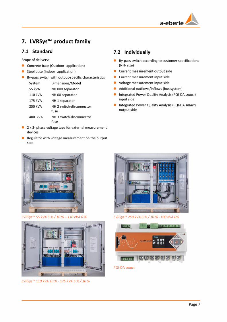
7. LVRSys™ product family
7.1 Standard
Scope of delivery:
0 Concrete base (Outdoor- application)
0 Steel base (Indoor- application)
0 By-pass switch with output-specific characteristics
System Dimensions/Model
55 kVA NH 000 separator
110 kVA NH 00 separator
175 kVA NH 1 separator
250 kVA NH 2 switch-disconnector
fuse
400 kVA NH 3 switch-disconnector
fuse
0 2 x 3- phase voltage taps for external measurement
devices
0 Regulator with voltage measurement on the output
side
7.2 Individually
0 By-pass switch according to customer specifications
(NH- size)
0 Current measurement output side
0 Current measurement input side
0 Voltage measurement input side
0 Additional outflows/inflows (bus system)
0 Integrated Power Quality Analysis (PQI-DA smart)
input side
0 Integrated Power Quality Analysis (PQI-DA smart)
output side
LVRSys™ 55 kVA 6 % / 10 % – 110 kVA 6 %
LVRSys™ 110 kVA 10 % - 175 kVA 6 % / 10 %
LVRSys™ 250 kVA 6 % / 10 % - 400 kVA 6%
PQI-DA smart
We take care of it.
A. Eberle GmbH & Co. KG
Frankenstraße 160
D-90461 Nuremberg
Tel.: +49 (0) 911 / 62 81 08 0
Fax: +49 (0) 911 / 62 81 08 99
Email: [email protected]
http://www.a-eberle.de
Edition of: 19/11/2014
Copyright 2014 A. Eberle GmbH & Co. KG
Subject to change without prior notice.