Order form Masterpact NT or NW Circuit breaker and switch ...

Low voltage electrical distribution
Masterpact NWCircuit breakers and switch-disconnectorsfrom 800 to 6300 A
User manual09/2009

������������� ��������������������
�����������

User manual for circuit breakers and switch-disconnectors Masterpact NW08-63 IEC
104443720AA - 09/2009
Contents
Identifying Masterpact 2Rating plate 2Discovering Masterpact 4Components 4Using Masterpact 8Understanding the controls and indications 8Charging the circuit breaker 9Closing the circuit breaker 10Opening the circuit breaker 11Resetting after a fault trip 12Locking the controls 13Using the Masterpact drawout chassis 16Identifying the circuit breaker positions 16Racking 17Matching a Masterpact circuit breaker with its chassis 19Locking the switchboard door 20Locking the circuit breaker in position 21Locking the safety shutters 24Identifying the electrical auxiliaries 26Identification of the connection terminals 26Electrical diagrams 27Operation 29Discovering Masterpact's accessories 30Micrologic control units 30Indication contacts 31Auxiliaries for remote operation 33Device mechanical accessories 35Chassis mechanical accessories 37Inspecting and testing before use 40Initial tests 40What to do when the circuit breaker trips 41Maintaining Masterpact performance 42Recommended maintenance program 42Maintenance operations 43Ordering replacement parts 45Troubleshooting and solutions 46Checking Masterpact operating conditions 48Environmental conditions 48

2 04443720AA - 09/2009
The Masterpact NW range of circuit breakers and switch-disconnectors offer current ratings from 800 A to 6300 A.Five different performance levels are available:
N1: standard with total discriminationH1: high performance with total discriminationH2: a compromise between current limiting and discriminationH3: high breaking capacity and discrimination, without current limitingL1: high level of current limiting, with some discrimination.
bbbbb
Rating plate
DB
11
87
44
DB
11
83
27
DB
11
87
43
DB
11
83
74
Icu kA at 415 VIcs = 100% Icu150
100
65
42
L1 H3H2
H1
N1
160012001000800 2000 2500 3200 4000 5000 6300
Rating plateIdentifying Masterpact

304443720AA - 09/2009

4 04443720AA - 09/2009
Discovering Masterpact
Masterpact circuit breakers are available in drawout and fixed versions.The drawout version is mounted on a chassis and the fixed version is installed using fixing brackets.
Drawout version
Fixed version
DB
11
83
75
DB
11
83
76
Components

504443720AA - 09/2009
Chassis
DB
11
87
45
Discovering Masterpact Components
6 04443720AA - 09/2009
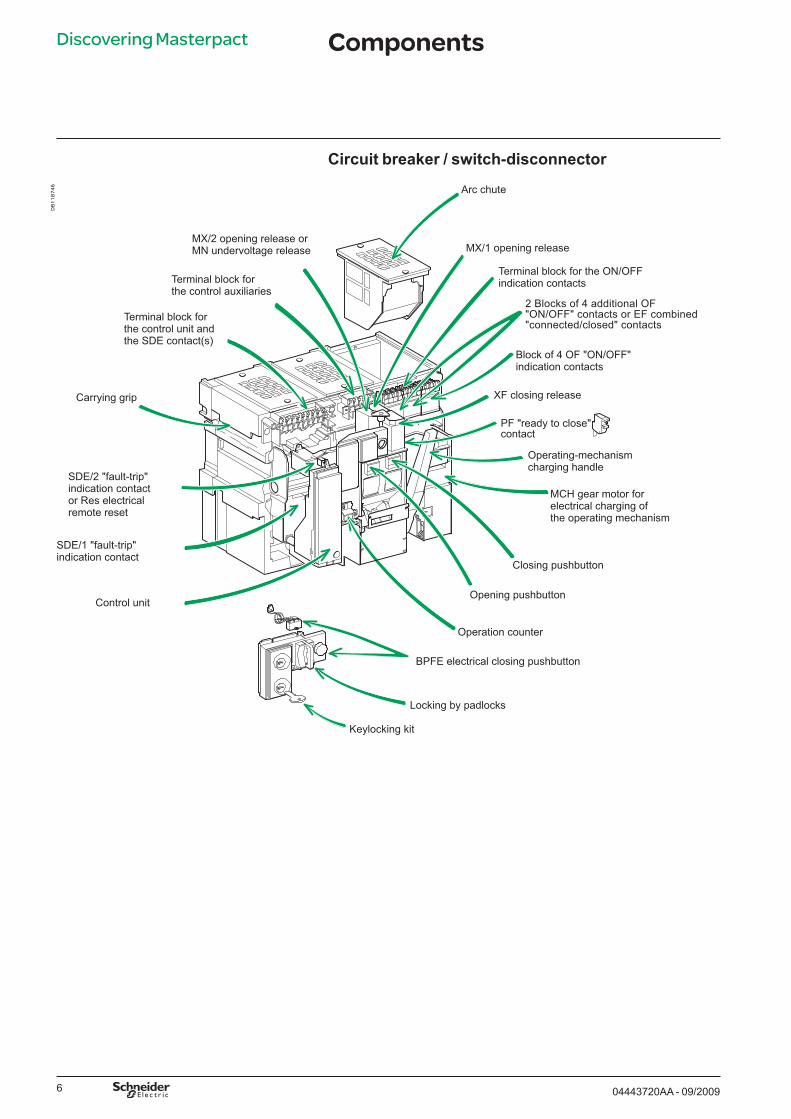
Circuit breaker / switch-disconnector
DB
11
87
46
MCH gear motor forelectrical charging ofthe operating mechanism
Operating-mechanismcharging handle
PF "ready to close"contact
SDE/2 "fault-trip"indication contactor Res electricalremote reset
Terminal block forthe control unit andthe SDE contact(s)
MX/2 opening release orMN undervoltage release
XF closing release
MX/1 opening release
Closing pushbutton
Opening pushbutton
Operation counter
Carrying grip
SDE/1 "fault-trip"indication contact
Arc chute
Block of 4 OF "ON/OFF"indication contacts
Terminal block forthe control auxiliaries
2 Blocks of 4 additional OF"ON/OFF" contacts or EF combined"connected/closed" contacts
Keylocking kit
Locking by padlocks
BPFE electrical closing pushbutton
Control unit
Terminal block for the ON/OFFindication contacts
Discovering Masterpact Components

704443720AA - 09/2009
Front
DB
11
87
47
RESET
Indicator for positionof the main contacts
"Springs charged"and "Ready to close"indicator
Locking by padlockor lead-seal coverfor pushbuttons
Rating plate
Trip indication buttonused to reset before closing
Discovering Masterpact Components

8 04443720AA - 09/2009
Using Masterpact Understanding the controls and indications
Circuit breaker open and discharged
Circuit breaker closed and discharged
Circuit breaker open, charged and not "ready to close"
Circuit breaker closed, charged and not "ready to close"
Circuit breaker open, charged and "ready to close"
DB
11
83
32
DB
11
83
79
DB
11
83
77
DB
11
83
80
DB
11
83
81
DB
11
83
78

904443720AA - 09/2009
The charge status is indicated as follows. The springs in the circuit breaker operating mechanism must be charged to store the energy required to close the main contacts. The springs may be charged manually using the charging handle or the optional MCH gear motor.
Manual charging:Pull the handle down seven times until you hear a "clack".
Automatic charging:If the MCH gear motor is installed, the spring is automatically recharged after each closing.
DB
11
87
48
DB
11
83
34
DB
11
83
82
Charging the circuit breaker
Push OFFO
IPush ON
or
Using Masterpact

10 04443720AA - 09/2009
Using Masterpact Closing the circuit breaker
Locally (electrical)
Closing conditionsClosing (i.e. turning the circuit ON) is possible only if the circuit breaker is "ready to close". The prerequisites are the following:
device open (OFF)springs chargedno opening order present.
If the circuit breaker is not "ready to close" when the order is given, stop the order and start again when the circuit breaker is "ready to close".
Closing the circuit breakerLocally (mechanical)Press the mechanical ON pushbutton.
bbb
Remotely
Enabling or disabling the anti-pumping functionThe purpose of the mechanical anti-pumping function is to ensure that a circuit breaker receiving simultaneous opening and closing orders does not open and close indefinitely.If there is a continuous closing order, after opening the circuit breaker remains open until the closing order is discontinued. A new closing order then closes the circuit breaker. This function can be disabled by wiring the closing release in series with the PF "ready to close" contact.
Press the electrical closing pushbutton. By adding an XF closing release, the circuit breaker can be closed remotely.
BPFE XF
When connected to a remote control panel, the XF closing release (0.85 to 1.1 Un) can be used to close the circuit breaker remotely.
XF
DB
11
83
83
DB
11
83
84
DB
11
83
85
DB
11
83
87
DB
11
83
86
DB
11
83
35
DB
11
83
88
DB
11
83
88
Device not "ready to close"
Device "ready to close"

1104443720AA - 09/2009
Opening the circuit breaker
LocallyPress the OFF pushbutton.
RemotelyUse one of the following solutions:
one or two MX opening releases (MX1 and MX2, 0.7 to 1.1 Un)one MN undervoltage release (0.35 to 0.7 Un)one MN undervoltage release (0.35 to 0.7 Un) with a delay unit (R or Rr).
When connected to a remote control panel, these releases can be used to open the circuit breaker remotely.
bbb
DB
11
83
85
DB
11
83
35
DB
11
83
88
DB
11
83
90
DB
11
83
89
MX1, MX2, MN Delay unit
Using Masterpact

12 04443720AA - 09/2009
Using Masterpact
The circuit breaker signals a fault by:a mechanical indicator on the front panelone or two SDE "fault-trip" indication contacts (SDE/2 is optional).
LocallyIf the circuit breaker is not equipped with the automatic reset option, reset it manually.
bb
Resetting after a fault trip
RemotelyUse the Res electrical remote reset option (not compatible with an SDE/2).
DB
11
83
85
DB
11
83
92
DB
11
83
35
DB
11
83
91
1304443720AA - 09/2009
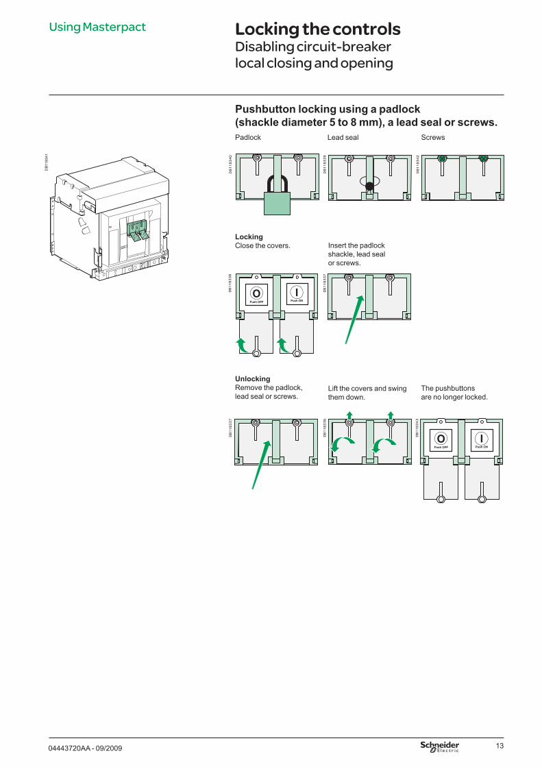
Locking the controlsDisabling circuit-breaker local closing and opening
Pushbutton locking using a padlock (shackle diameter 5 to 8 mm), a lead seal or screws.
DB
1183
41
UnlockingRemove the padlock, lead seal or screws.
DB
11
83
40
DB
11
83
39
DB
11
83
38
DB
11
83
37
Padlock Lead seal
LockingClose the covers. Insert the padlock
shackle, lead seal or screws.
DB
11
83
37
DB
11
83
36
DB
11
83
43
Lift the covers and swing them down.
The pushbuttons are no longer locked.
DB
11
83
42
Screws
Using Masterpact

14 04443720AA - 09/2009
Combination of locking systemsTo disable circuit-breaker closing using the pushbuttons or remotely, use as needed:
a padlock one or two keylocks a combination of the two locking system.
Install a padlock (maximum shackle diameter 5 to 8 mm)LockingOpen the circuit breaker.
bbb
Using Masterpact Locking the controlsDisabling local and remote closing
DB
11
83
89
CheckThe controls are inoperative.
UnlockingRemove the padlock.
DB
11
83
45
DB
11
83
44
Pull out the tab. Insert the padlock shackle.
DB
11
83
46
DB
11
83
47
�� �
����
����� ��
���� ����

1504443720AA - 09/2009
Locking the controls with one or two keylocksLockingOpen the circuit breaker. Remove the key(s).Turn the key(s).
CheckThe controls are inoperative.
DB
11
83
46
�� �
����
����� ��
���� ����
UnlockingInsert the key(s).
Four types of keylocks are available.
DB
11
83
93
DB
11
83
49
DB
11
83
48
DB
11
84
02
DB
11
87
49
Turn the key(s). The key(s) cannot be removed.
RONIS PROFALUX CASTELL
DB
11
83
96
KIRK
DB
11
83
89
DB
11
83
51
DB
11
83
50
DB
11
83
94
Using Masterpact Locking the controlsDisabling local and remote closing

16 04443720AA - 09/2009
Using the Masterpact drawout chassis
Identifying the circuit breaker positions
"connected" positionb
DB
11
83
54
The indicator on the front signals the position of the circuit breaker in the chassis.
DB
11
83
98
"test" positionb
DB
11
83
97
DB
11
83
53
"disconnected" positionb
DB
11
83
99
DB
11
83
55
DB
11
83
52

1704443720AA - 09/2009
Racking
PrerequisitesTo connect and disconnect Masterpact, the crank must be used. The locking systems, padlocks and the racking interlock all inhibit use of the crank.
Withdrawing the circuit breaker from the "connected" to "test" position, then to "disconnected" position
Removing the rails
The circuit breaker is in "connected" position.
DB
11
87
50
The circuit breaker is in "test" position.
The circuit breaker is in "disconnected" position.
The circuit breaker is in "test" position.Remove the crank or continue to "disconnected" position.
Press the release tabs and pull the rails out.
To put the rails back in, press the release tabs and push the rails in.
DB
11
83
58
DB
11
83
56
These operations require that all chassis-locking functions be disabled (see page 21).
Caution. The right-hand rail cannot be removed if the crank has not been removed or if the circuit breaker is not fully disconnected.
Using the Masterpact drawout chassis

18 04443720AA - 09/2009
Position the circuit breaker on the rails.Check that it rests on all four supports.
DB
11
83
60
Open the circuit breaker (in any case, it opens automatically during connection).
DB
11
83
89
Push the circuit breaker into the chassis, taking care not to push on the control unit.
DB
11
83
51
For complete information on Masterpact handling and mounting, see the installation manual(s).
Before mounting the circuit breaker, make sure it matches the chassis.
Racking the circuit breaker from the "disconnected" to "test" position, then to "connected" position
The device is in "disconnected" position.
The device is in "test" position.
Using the Masterpact drawout chassis
Racking
Inserting Masterpact
The device is in "test" position. Remove the crank or continue to "connected" position.
The device is in "connected" position.
If you cannot insert the circuit breaker in the chassis, check that the mismatch protection on the chassis corresponds to that on the circuit breaker.
DB
11
83
59

1904443720AA - 09/2009
Matching a Masterpact circuit breaker with its chassis
To set up a mismatch-prevention combination for the circuit breaker and the chassis, see the mismatch-prevention installation manual.
DB
11
83
62
The mismatch protection ensures that a circuit breaker is installed only in a chassis with compatible characteristics.
The possible combinations are listed below.
Using the Masterpact drawout chassis

20 04443720AA - 09/2009
Locking the switchboard door
Disabling door openingClose the door.
DB
11
83
64
Enabling door openingPut the Masterpact in "disconnected" position.
DB
11
84
00
The door is unlocked.
The locking device is installed on the left or right-hand side of the chassis:when the circuit breaker is in "connected" or "test" position, the latch is lowered
and the door is lockedwhen the circuit breaker is in "disconnected" position, the latch is raised
and the door is unlocked.
b
b
DB
11
83
66
DB
11
84
01
DB
11
83
63
DB
11
83
65
Put the Masterpact in "test" or "connected" position.
The door is locked.
Using the Masterpact drawout chassis

2104443720AA - 09/2009
Locking the circuit breaker in position
Circuit breaker in "disconnected" position.
DB
1183
72Pull out the tab.
DB
1183
70
DB
1183
71
Insert the shackle (max. diameter 5 to 8 mm) of the padlock(s).
DB
1183
73
Padlocks and keylocks may be used together.
Unlocking.
Release the tab.
The crank can be inserted.
The crank cannot be inserted.
DB
1183
68
Combination of locking systemsTo disable local or remote opening or closing of the circuit breaker, use as needed:
one to three padlocksone or two keylocks a combination of the two locking systems.
Disabling connection when the circuit breaker is in "disconnected" position, using one to three padlocks (maximum shackle diameter 5 to 8 mm)Locking
bbb
Remove the padlock(s).
DB
1183
69D
B11
8367
Using the Masterpact drawout chassis

22 04443720AA - 09/2009
Using the Masterpact drawout chassis
Unlocking
Four types of keylocks are available
DB
1184
09
The crank can be inserted.Insert the key(s).
DB
1184
03
DB
1183
73
Turn the key(s).
DB
1183
94
RONIS
DB
1187
49
PROFALUX
DB
1183
93
CASTELL
DB
1183
96
KIRK
Padlocks and keylocks may be used together.
Remove the key(s). The crank cannot be inserted.
DB
1184
04
DB
1183
69
Locking the circuit breaker in position
Disabling connection when the circuit breaker is in "disconnected" position, using one or two keylocks.Locking
DB
1183
72
Circuit breaker in "disconnected" position.
DB
1184
05
Turn the key(s).

2304443720AA - 09/2009
Set the circuit breaker to "disconnected" position. Remove the circuit breaker from the chassis.
DB
1183
72
Insert the crank.
DB
1187
52
DB
1184
10
Turn the catch to the right. The circuit breaker can now be locked in all positions.
DB
1184
14
For this operation, the circuit breaker must be removed from the chassis.
Locking the circuit breaker when the door is open
When the door is open, the crank cannot be inserted.
DB
1184
13
When the door is closed, the crank can be inserted.
It is possible to modify the padlock and keylock locking function. Instead of locking only in "disconnected" position, it is possible to lock the circuit breaker in all positions
DB
1184
11
Disabling use of the crank in all positions
Using the Masterpact drawout chassis
Locking the circuit breaker in position

24 04443720AA - 09/2009
Using the Masterpact drawout chassis
Locking the safety shuttersPadlocking inside the chassis
Using the shutter locking blocks
Four locking possibilities
DB
1184
17
Remove the block(s) from their storage position.
DB
1184
19
Position the block(s) on the guide(s).
DB
1184
16
Lock the block(s) using a padlock.
DB
1184
15D
B11
8418
Top and bottom shutters not locked.
Top shutter locked,Bottom shutter not locked.
Top shutter not locked,Bottom shutter locked.
Top and bottom shutters locked.

2504443720AA - 09/2009
DB
1187
53D
B11
8422
DB
1184
21
Pull out the left-hand tab to lock the top shutter.
DB
1184
21
This system offers two functions:padlocking of the top or bottom shuttersindication of the position of each shutter:shutter openshutter closed.
bbvv
Locking
Pull out the right-hand tab to lock the bottom shutter.
Locking the safety shuttersPadlocking or position indication on the front
Insert a padlock (shackle 5 to 8 mm).
DB
1184
22
Unlocking
Insert a padlock (shackle 5 to 8 mm).
DB
1184
26
Remove the padlock. Release the tab(s).
DB
1184
20
Test
Test
Test
Test
Test
Top shutter closed.Bottom shutter open.
Top shutter open.Bottom shutter closed.
Top and bottomshutters open.
Top and bottomshutters closed.
DB
1184
25
DB
1184
24Pull out both tabs to lock both shutters.
Insert a padlock (shackle 5 to 8 mm).
Using the Masterpact drawout chassis

26 04443720AA - 09/2009
Identifying the electrical auxiliaries
Identification of the connection terminals Layout of terminal blocks
DB
1191
70

2704443720AA - 09/2009
Electrical diagramsFixed and drawout devices
The diagram is shown with circuits de-energised, all devices open, connected and charged and relays in normal position.
DB
1191
71
b b b
b b b
b b b
b b bb b b
b b b
b b
b b
b b b b
/
/
Power
Com: E1-E6 communication
UC1: Z1-Z5 zone selective interlocking; Z1 = ZSI OUT SOURCE Z2 = ZSI OUT; Z3 = ZSI IN SOURCE Z4 = ZSI IN ST (short time) Z5 = ZSI IN GF (earth fault) M1 = Vigi module input (Micrologic 7)
UC2: T1, T2, T3, T4 = external neutral; M2, M3 = Vigi module input (Micrologic 7)
UC3: F2+, F1– external 24 V DC power supply VN external voltage connector
UC4: V1, V2, V3 optional external voltage protector
M2C: 2 programmable contacts (internal relay); ext. 24 V DC power supply requiredorM6C: 6 programmable contact (external relay); 24 V DC power supply required
Control unit
Control unit Remote operation
SDE2: Fault-trip indication contactorRes: Remote reset
SDE1: Fault-trip indication contact (supplied as standard)
MN: Undervoltage releaseorMX2: Shunt release
MX1: Shunt release (standard or communicating) XF: Closing release (standard or communicating)
PF : "Ready to close" contact
MCH: Gear motor.
Note:When communicating MX or XF releases are used, the third wire (C3, A3) must be connected even if the communications module is not installed.
A : Digital ammeterP : A + power meter + programmable protectionH : P + harmonics
/
/
Remote operation
Remote operation SDE2 / Res SDE1 MN / MX2 MX1 XF PF MCH
184 K2 84 D2 C12 C2 A2 254 B2
182 82 C3 A3 252 B3
181 K1 81 D1 C11 C1 A1 251 B1
/ / /
Control unit
Com UC1 UC2 UC3 UC4 M2C / M6C
E5 E6 Z5 M1 M2 M3 F2+ V3 484 Q3 E3 E4 Z3 Z4 T3 T4 VN V2 474 Q2
E1 E2 Z1 Z2 T1 T2 F1 – V1 471 Q1
A P H
Identifying the electrical auxiliaries

28 04443720AA - 09/2009
Identifying the electrical auxiliaries
Electrical diagrams
OF24 or ON/OFF indication contacts EF24 Combined "connected/closed" indication contacts
OF23 or EF23
OF22 or EF22
OF21 or EF21
OF14 or EF14
OF13 or EF13
OF12 or EF12
OF11 or EF11
OF4: ON/OFF OF3 indication OF2 contacts OF1
OF24 OF23 OF22 OF21 OF14 OF13 OF12 OF11 244 234 224 214 144 134 124 114
242 232 222 212 142 132 122 112
241 231 221 211 141 131 121 111
DB
1014
09
Indication contacts
Indication contacts
CD3: Disconnected CD2 -position CD1 contacts
or CE6: Connected CE5 position CE4 contacts
CT3: Test-positionCT2 contacts CT1 contacts
or
CE9: ConnectedCE8 positionCE7 contacts
or
CD6: DisconnectedCD5 positionCD4 contacts
or or or or or or or or
CD3 CD2 CD1 CE3 CE2 CE1 CT3 CT2 CT1 834 824 814 334 324 314 934 924 914
832 822 812 332 322 312 932 922 912
831 821 811 331 321 311 931 921 911
CE6 CE5 CE4 CE9 CE8 CE7 364 354 344 394 384 374
362 352 342 392 382 372
361 351 341 391 381 371
or or
CE3: Contacts CE2 de position CE1 "embroché"
Indication contacts OF4 OF3 OF2 OF1 44 34 24 14
42 32 22 12
41 31 21 11
Chassis contacts
Key:
Drawout device only
SDE1, OF1, OF2, OF3, OF4 supplied as standard
Interconnected connections (only one wire per connection point)
XXX
Chassis contacts
Chassis contacts
EF24 EF23 EF22 EF21 EF14 EF13 EF12 EF11 248 238 228 218 148 138 128 118
246 236 226 216 146 136 126 116
245 235 225 215 145 135 125 115

2904443720AA - 09/2009
DB
1191
72
Operation
The carriage switches indicate the "connected", "test" and "disconnected" positions.
Circuit breaker
Chassis
open
closed
closed
completely closed completely open
main contacts
OF : ON/OFF (closed/open)indication changeover contacts
closed
open
open
DB
1191
73
The ON/OFF indication contacts signal the status of the device main contacts.
test position
separation of the auxiliary circuits separation of the main circuits
completely connected
completely disconnected
open
open
open
closed
closed
d> 12.7 mm d> 25.4 mm
open
open
open
closed
closed
closed
closedCT: test positioncarriage switch
CD: disconnected-positioncarriage switch
CE: connected-positioncarriage switch
open
closed
Identifying the electrical auxiliaries

30 04443720AA - 09/2009
Discovering Masterpact's accessories
Micrologic control units
E51
329A
E46
108A
For more in-depth information, see the control-unit user manual.
Micrologic control units
Long-time rating plugs
M2C and M6C programmable contacts
Standard equipment, one per device.
Long-time rating plug and connection cables not included, see below:Micrologic 2.0Micrologic 5.0Micrologic 2.0 AMicrologic 5.0 AMicrologic 6.0 AMicrologic 7.0 AMicrologic 5.0 PMicrologic 6.0 PMicrologic 7.0 PMicrologic 5.0 HMicrologic 6.0 HMicrologic 7.0 H
Connection cables: for fixed devicefor drawout device.
b
b
bvv
Depending on the model, control units offer in addition:
fault indicationsmeasurement of
electrical parameters (current, voltage, power, etc)
harmonic analysiscommunication.
b
vv
vv
M2C: 2 contacts (6 A-240 V)
M6C: 6 contacts (6A-240V).
Permissible load on each of the M6C relay outputs;
240 V AC: 5 A where p.f = 0.7
380 V AC: 3 A where p.f = 0.7
24 V DC: 8 A where L/R = 0
48 V DC: 1.5 A where L/R = 0
125 V DC: 0.4 A where L/R = 0
250 V DC: 0.15 A where L/R = 0
M6C supply voltage: 24 V DC ± 5%
M6C maximum consumption: 100 mA
b
b
b
v
v
v
v
v
v
b
b
Standard equipment, one per control unit.
0.4 to 1 x Ir setting0.4 to 0.8 x Ir setting0.8 to 1 x Ir settingOff (no long-time
protection.
b
vvvv
The plugs determine the setting range for the Long-time protection.
b
Optional equipment, used with Micrologic P and H control units.
Connection cables not included, see below:
2 M2C contacts6 M6C contactsConnection cables:for fixed devicefor drawout device.
b
b
vvbvv
Contacts can be programmed using the keypad on the control unit or via the COM option.
They indicate:the type of faultinstantaneous or
delayed threshold overruns.
b
bvv

3104443720AA - 09/2009
Indication contacts
ON/OFF indication contacts (OF)4 changeover contactsRated current: 10 A.Breaking capacity
50/60 Hz for AC power (AC12 as per 947-5-1):
480 V: 10 A (rms)600 V: 6 A (rms).Breaking capacity
for DC power (DC12 as per 947-5-1):250 V: 3 A.
bbb
vvb
E51
331A Additional ON/OFF indication contacts (OF)
Optional equipment, two blocks of 4 OF contacts per device
Connection cables not included, see below: one block of 4 OF contacts
Connection cables:for fixed devicefor drawout device.
b
b
bvv
Changeover contactsRated current: 10 ABreaking capacity
50/60 Hz for AC power (AC12 as per 947-5-1):
480 V: 10 A (rms)600 V: 6 A (rms)Breaking capacity
for DC power (DC12 as per 947-5-1):250 V: 3 A.
bbb
vvb
Combined "connected/closed" contacts (EF)Optional equipment, 8
EF contacts per deviceEach contact is
mounted in place of the connector of an additional OF contact
One EF contact.
b
b
b
The contact combines the "device connected" and the "device closed" information to produce the "circuit closed" information.
b Changeover contactsRated current: 10 ABreaking capacity
50/60 Hz for AC power (AC12 as per 947-5-1):
240 V: 10 A (rms)380 V: 10 A (rms)480 V: 10 A (rms)600 V: 6 A (rms)Breaking capacity
for DC power (DC12 as per 947-5-1):
48 V: 2.5 A130 V: 0.8 A250 V: 0.3 A.
bbb
vvvvb
vvv
"Fault-trip" indication contact (SDE/1)Standard equipment on
circuit breakers, one SDE/1 contact per device
Not available for switch-disconnector versions.
b
b
Changeover contactRated current: 10 ABreaking capacity
50/60 Hz for AC power (AC12 as per 947-5-1):
240 V: 10 A (rms)380 V: 5 A (rms)480 V: 5 A (rms)600 V: 3 A (rms)Breaking capacity
for DC power (DC12 as per 947-5-1):
48 V: 3 A125 V: 0.3 A250 V: 0.15 A.
bbb
vvvvb
vvv
Standard equipment: 4 OF per device.b OF contacts indicate
the position of main contacts
They trip when the minimum isolation distance between the main contacts is reached.
b
b
OF contacts indicate the position of the main contacts
They trip when the minimum isolation distance between the main contacts is reached
b
b
The contact provides a remote indication of device opening due toan electrical fault.
b
Discovering Masterpact's accessories

32 04443720AA - 09/2009
Discovering Masterpact's accessories
DB
11
83
91
Optional equipment for circuit breakers, one additional SDE/2 contact per device
Not available for switch-disconnector versions
Not compatible with the Res option
Connection cables not included, see below: one SDE/2 contact
Connection cables:for fixed devicefor drawout device.
b
b
b
b
bvv
Additional "fault-trip" indication contact (SDE/2)The contact remotely
indicates device opening due to an electrical fault.
b
DB
11
83
91
E51
332A
Changeover contactRated current: 10 ABreaking capacity
50/60 Hz for AC power (AC12 as per 947-5-1):
240 V: 10 A (rms)380 V: 5 A (rms)480 V: 5 A (rms)600 V: 3 A (rms)Breaking capacity
for DC power (DC12 as per 947-5-1):
48 V: 3 A125 V: 0.3 A250 V: 0.15 A.
bbb
vvvvb
vvv
Optional equipment, one Res per device
Not compatible with the SDE/2 option
Connection cables not included, see below:110/130 V AC220/240 V AC
Connection cables:for fixed devicefor drawout device.
b
b
b
bvv
Electrical reset after fault trip (Res)The contact remotely
resets the device following tripping due to an electrical fault.
b
"Springs charged" limit switch contact (CH)The contact indicates
the "charged" status of the operating mechanism (springs charged).
b
"Ready to close" contact (PF)
Indication contacts
Standard equipment, one CH contact per devicel.
b Changeover contactRated current: 10 ABreaking capacity
50/60 Hz for AC power (AC12 as per 947-5-1):
240 V: 10 A (rms)380 V: 5 A (rms)480 V: 5 A (rms)600 V: 3 A (rms)Breaking capacity
for DC power (DC12 as per 947-5-1):
48 V: 3 A125 V: 0.3 A250 V: 0.25 A.
bbb
vvvvb
vvv
Optional equipment, one PF contact per device
Connection cables not included, see below: one PF contact
Connection cables:for fixed devicefor drawout device.
b
b
bvv
The contact indicates that the device may be closed because all the following are valid:
circuit breaker is openspring mechanism is
chargeda maintained closing
order is not presenta maintained opening
order is not present.
b
vv
v
v
Changeover contactRated current: 10 ABreaking capacity
50/60 Hz for AC power (AC12 as per 947-5-1):
240 V: 10 A (rms)380 V: 5 A (rms)Breaking capacity
for DC power (DC12 as per 947-5-1):
48 V: 3 A125 V: 0.3 A250 V: 0.15 A.
bbb
vvb
vvv

3304443720AA - 09/2009
Auxiliaries for remote operation
Moto-réducteur MCHThe gear motor
automatically charges and recharges the spring mechanism.
b Charging time: 4 seconds max.
Consumption:180 VA AC180 W DCInrush current:
2 to 3 In for 0.1 secondOperating rate:
maximum 3 cycles per minute.
b
bvvb
b
DB
1183
82D
B11
8388 Opening releases MX/1 and MX/2, closing release XF
Optional equipment, 1 or 2 MX releases per device, 1 XF per device
The function (MX or XF) is determined by where the coil is installed
Connection cables not included, see below:
standard version:- 12 V AC 50/60 Hz / DC- 24/30 V AC 50/60 Hz / DC- 48/60 V AC 50/60 Hz / DC- 100/130 V AC 50/60 Hz / DC- 200/250 V AC 50/60 Hz / DC- 277 V AC 50/60 Hz / DC- 380/480 V AC 50/60 Hz / DC.
communicating version (with COM option):- 12 V AC 50/60 Hz / DC- 24/30 V AC 50/60 Hz / DC- 48/60 V AC 50/60 Hz / DC- 100/130 V AC 50/60 Hz / DC- 200/250 V AC 50/60 Hz / DC- 240/277 V AC 50/60 Hz / DC- 380/480 V AC 50/60 Hz / DC.
b
b
b
v
v
Connection cables:for fixed devicefor drawout deviceThe MX release
instantaneously opens the circuit breaker when energised
The XF release instantaneously closes the circuit breaker when energised, if the device is "ready to close".
bvvb
b
Device response time: MX: 50 ms ± 10XF: 70 ms +10 / -15
> 3200 A: 80 ms ± 10Operating threshold:MX: 0.7 to 1.1 x UnXF: 0.85 to 1.1 x UnThe supply can be
maintainedConsumption:pick-up (80 ms):
200 VAhold: 4.5 VA.
bvv
bvvb
bv
v
Optional equipment, one MCH gear motor per device
Connection cables not included, see below:100/130 V AC200/240 V AC277 V AC380/415 V AC400/440 V AC480 V AC24/30 V DC48/60 V DC100/125 V DC200/250 V DC
Connection cables:for fixed devicefor drawout device.
b
b
bvv
Discovering Masterpact's accessories

34 04443720AA - 09/2009
Discovering Masterpact's accessories
Instantaneous undervoltage releases (MN)Optional equipment,
1 MN per deviceNot compatible with the
MX/2 opening releaseConnection cables not
included, see below:24/30 V AC
50/60 Hz / DC48/60 V AC
50/60 Hz / DC100/130 V AC
50/60 Hz / DC200/250 V AC
50/60 Hz / DC380/480 V AC
50/60 Hz / DCConnection cables:for fixed devicefor drawout device.
b
b
b
v
v
v
v
v
bvv
The MN release instantaneously opens the circuit breaker when its supply voltage drops.
b Device response time: 90 ms ±5
Operating threshold:opening:
0.35 to 0.7 x Unclosing: 0.85 x UnConsumption:pick-up (80 ms):
200 VAhold: 4.5 VA.
b
bv
vbv
v
Auxiliaries for remote operationD
B11
8388
DB
1183
90
Optional equipment, 1 MN with delay unit per device.
Delay-unit (must be ordered in addition to the MN):
48/60 V AC 50/60 Hz / DC
100/130 V AC 50/60 Hz / DC
200/250 V AC 50/60 Hz / DC
380/480 V AC 50/60 Hz / DC.
b
b
v
v
v
v
Delay unit for MN releasesThe unit delays
operation of the MN release to eliminate circuit-breaker nuisance tripping during short voltage dips
The unit is wired in series with the MN and must be installed outside the circuit breaker.
b
b
E51
333A
Device response time: 0.5, 1, 1.5, 3 seconds
Operating threshold:opening:
0.35 to 0.7 x Unclosing: 0.85 x UnConsumption: pick-up (80 ms):
200 VAhold: 4.5 VA.
b
bv
vbv
v
Optional equipment, 1 BPFE per device
Connection cables not included, see below:
Connection cables:for fixed devicefor drawout device.
b
b
bvv
Electrical closing pushbutton (BPFE)Located on the front
face of the device, this pushbutton carries out electrical closing of the circuit breaker via the XF release, taking into account all the safety functions that are part of the control/monitoring system of the installation.
b

3504443720AA - 09/2009
Device mechanical accessories
Operation counter (CDM)Optional equipment,
one CDM per device.b The operation counter
sums the number of operating cycles.
b
E46
103A
E46
120A
E46
118A
00399
Escutcheon (CDP)Optional equipment,
one CDP per devicefor fixed devicefor drawout device.
b
vv
The CDP increases the degree of protection to IP 40 and IK 07 (fixed and drawout devices).
b
Transparent cover (CCP)Optional equipment,
one CP per device equipped with a CDP (for fixed and drawout devices).
b Mounted with a CDP, the CP increases the degree of protection to IP 55 and IK 10 (fixed and drawout devices).
b
Discovering Masterpact's accessories

36 04443720AA - 09/2009
Device mechanical accessoriesDiscovering Masterpact's accessories
E46
238A
E46
579A
Transparent cover for pushbutton locking using a padlock, lead seal or screws
Optional equipment, one locking cover per device.
b The transparent cover blocks access (together or separately) to the pushbuttons used to open and close the device
Locking requires a padlock, a lead seal or two screws.
b
b
Device locking in the OFF position using a padlockOptional equipment,
one locking system per device.
b The unit inhibits local or remote closing of the device
Up to three padlocks may be used for locking.
b
b
Device OFF position locking kit for keylocksOptional equipement,
one locking kit per deviceLocks not included:for Profalux or Ronis
keylocksfor Castell keylocksfor Kirk keylocks.
b
bv
vv
The kit inhibits local or remote closing of the device.
b
Keylocks required for the device locking kit
E51
286A
E51
273A
DB
1191
80
DB
1191
91
Ronis
Profalux
One or two keylocks per locking kit
Ronis: 1 keylock2 keylocks.
Profalux: 1 keylock2 keylocks.
b
v
v

3704443720AA - 09/2009
Chassis mechanical accessories
Safety shuttersOptional equipmentSet of shutters for top
and bottom:NW08/NW40
3 poles4 poles
NW40b/NW63 3 poles4 poles.
bb
v
v
Mounted on the chassis, the safety shutters automatically block access to the disconnecting contact cluster when the device is in the "disconnected" or "test" positions.
b IP20.b
E51
334A
E46
293A Shutter locking blocks
Optional equipment: 2 blocks for NW08 to NW40 4 blocks for NW40b to NW63.
b The block may be padlocked. It:
prevents connection of the device
locks the shutters in the closed position.
b
v
v
Shutter position indication and locking on front faceOptional equipmentNW08/NW040
3 and 4 polesNW40b/NW63
3 poles4 poles.
bv
v
This option located on the front of the chassis:
indicates that the shutters are closed
can be used to independently or simultaneously padlock the two shutters (top and bottom).
b
v
v
Circuit breaker locking in "disconnected" position
Keylocks required with the "disconnected" position locking system
One or two keylocks per locking system
Ronis:1 keylock2 keylocks
Profalux:1 keylock2 keylocks.
b
v
v
E46
946A
E46
561A
Top shutter closed Bottom shutter closed
Optional equipment, one locking system per device
for Profalux or Ronis keylocks
for Castell keylocksfor Kirk keylocks.
b
v
vv
Mounted on the chassis and accessible with the door closed, this system locks the circuit breaker in "disconnected" position using one or two keylocks
The "disconnected" position locking system may be modified to lock the circuit breaker in all three positions.
b
b
E51
286A
E51
273A
DB
1191
80
DB
1191
91
Ronis
Profalux
Discovering Masterpact's accessories

38 04443720AA - 09/2009
Discovering Masterpact’s accessories
Door interlockOptional equipment,
one door interlock per chassis.
b This device inhibits opening of the cubicle door when the circuit breaker is in "connected" or "test" position.
b It may be mounted on the left or right-hand side of the chassis.
b
E46
652A
E46
124A Racking interlock
Mismatch protection
Auxiliary terminal shield (CB)
E46
111A
E51
351A
Chassis mechanical accessories
Optional equipment, one racking interlock per chassis.
b This device prevents insertion of the racking handle when the cubicle door is open.
b It is mounted on the right-hand side of the chassis.
b
Optional equipment, one mismatch protection device per chassis.
b Mismatch protection offers twenty different combinations that the user may select to ensure that only a compatible circuit breaker is mounted on a given chassis.
b
Optional equipment, one CB shield per chassis
NW08/NW0403 poles4 poles
NW40b/NW633 poles4 poles.
b
v
v
The shield prevents access to the terminal block of the electrical auxiliaries.
b

3904443720AA - 09/2009
"Connected", "disconnected" and "test" position carriage switches (CE, CD, CT)
Optional equipment, one to nine carriage switches
Standard configuration, 0 to 3 CE, 0 to 3 CD, 0 to 3 CT
Other configurations (by ordering additional actuators):0 to 9 CE, 0 CD, 0 CT0 to 6 CE, 0 to 3 CD, 0 CT0 to 6 CE, 0 CD, 0 to 3 CT
Connection cables not included, see below:
1 carriage switch1 set of actuators for
additional carriage switches
Connection cables (per carriage switch).
b
b
b
b
vv
b
The carriage switches indicate the three positions:CE: connected positionCD: disconnected position (when the minimum isolation distance between the main contacts and the auxiliary contacts is reached)CT: test position.
b Changeover contactRated current: 10 ABreaking capacity
50/60 Hz for AC power (AC12 as per 947-5-1):240 V: 10 A (rms)380 V: 5 A (rms)
Breaking capacity for DC power (DC12 as per 947-5-1):250 V: 0.3 A.
bbb
b
E46
095A
Discovering Masterpact’s accessories
Chassis mechanical accessories

40 04443720AA - 09/2009
Inspecting and testing before use
Initial testsProcedure
A general check of the circuit breaker takes only a few minutes and avoids any risk of mistakes due to errors or negligence.A general check must be carried out:
Prior to initial useFollowing an extended period during which the circuit breaker is not used.
Toute A check must be carried out with the entire switchboard de-energised.In switchboards with compartments, only those compartments that may be accessed by the operators must be de-energised.
Electrical testsInsulation and dielectric-withstand tests must be carried out immediately after delivery of the switchboard. These tests are precisely defined by international standards and must be directed and carried out by a qualified expert.
Prior to running the tests, it is absolutely necessary to:Disconnect all the electrical auxiliaries of the circuit breaker
(MCH, MX, XF, MN, Res electrical remote reset)Remove the long-time rating plug on the 7.0 A, 5.0 P, 6.0 P, 7.0 P, 5.0 H, 6.0 H, 7.0 H
control units. Removal of the rating plug disconnects the voltage measurement input.
Switchboard inspectionCheck that the circuit breakers are installed in a clean environment, free of any installation scrap or items (tools, electrical wires, broken parts or shreds, metal objects, etc.).
Conformity with the installation diagramCheck that the devices conform with the installation diagram:
Breaking capacities indicated on the rating platesIdentification of the control unit (type, rating)Presence of any optional functions (remote ON/OFF with motor mechanism,
auxiliaries, measurement and indication modules, etc.)Protection settings (long time, short time, instantaneous, earth fault)Identification of the protected circuit marked on the front of each circuit breaker.
Condition of connections and auxiliariesCheck device mounting in the switchboard and the tightness of power connections.Check that all auxiliaries and accessories are correctly installed:
Electrical auxiliariesTerminal blocksConnections of auxiliary circuits.
OperationCheck the mechanical operation of the circuit breakers:
Opening of contactsClosing of contacts.
Check on the control unitCheck the control unit of each circuit breaker using the respective user manuals.
bb
b
b
bbb
bb
bbb
bb
These operations must be carried out in particular before using a Masterpact device for the first time.

4104443720AA - 09/2009
Note the faultFaults are signalled locally and remotely by the indicators and auxiliary contacts installed on circuit breakers (depending on each configuration). See page 12 in this manual and the user manual of the control unit for information on the fault indications available with your circuit breaker.
Identify the cause of trippingA circuit must never be reclosed (locally or remotely) before the cause of the fault has been identified and cleared.
A fault may have a number of causes:depending on the type of control unit, fault diagnostics are available. See the user
manual for the control unit.depending on the type of fault and the criticality of the loads, a number of
precautionary measures must be taken, in particular the insulation and dielectric tests on a part of or the entire installation. These checks and test must be directed and carried out by qualified personnel.
Inspect the circuit breaker following a short-circuit Check the arc chutes (see page 43).Check the contacts (see page 43).Check the tightness of connections (see the device installation manual).Check the disconnecting-contact clusters (see page 44).
Reset the circuit breakerThe circuit breaker can be reset locally or remotely. See page 12 in this manual for information on how the circuit breaker can be reset.
b
b
bbbb
What to do when the circuit breaker trips
Inspecting and testing before use

42 04443720AA - 09/2009
Interval Operations ProcedureEach year Open and close the device
locally and remotely, successively using the various auxiliaries
Test the operating sequencesTest the control unit using the
mini test kit.
b
bb
see pages 10 and 11.
see page 8.see the user manual
of the control unit.
v
vv
Every two years or when the control-unit maintenance indicatorreaches 100
Check the arc chutes Check the main contactsCheck the tightness of
connectionsCheck the disconnecting-contact
clusters
bbb
b
see page 43see page 43see the device
installation manualsee page 44
vvv
v
Maintaining Masterpact performance
Recommended maintenance program
Periodic inspections required
Type of circuit breaker
Maximum service life Service life of various parts
Arc chuteschutes
MaincontactsMCH
Connecting-rod springs
MX/XFreleases
NW08 to NW16types N1/H1/H2
25000 10000 10000 12500 12500
NW08 to NW16type L1
25000 3000 10000 12500 12500
NW20types H1/H2
20000 440 V: 8000690 V: 6000
440 V: 8000690 V: 6000
10000 12500
NW20 to NW25type H3
20000 2000 440 V: 8000690 V: 6000
10000 12500
NW20type L1
20000 3000 10000 10000 12500
NW25 to NW40types H1/H2
20000 440 V: 5000690 V: 2500
440 V: 5000690 V: 2500
10000 12500
NW32 to NW40type H3
20000 1250 440 V: 5000690 V: 2500
10000 12500
NW40b to NW63types H1/H2
10000 1500 1500 5000 12500
Recommended program for devices used under normal operating conditions:Ambient temperature: -5° C / +60°CNormal atmosphere
Parts requiring replacement, depending on the number of operating cycles.The following parts must be replaced periodically to lengthen the service life of the device (maximum number of operating cycles).
Part replacement must be programmed on the basis of the data below, listing the service life of the various parts in numbers of O/C cycles at the rated current.
Number of O/C cycles at the rated current
Part Intervening entity Description or procedure
Arc chutes User.b see page 43.vMain contacts Inspection: user
Replacement: Schneider After Sales Support.
bb
see page 43.v
MCH gear motor User.b see page 9.v
Mechanical interlocks
User.b
Connecting-rod springs Schneider After Sales Support.b
MX/MN/XF User.b see page 10, 11.v

4304443720AA - 09/2009
Arc chutesRemove the fixing screws:types N1, H1 and H2 y NW 40: two screwstypes H1 and H2 u NW 40b, type H3: three screwstype L1: four screws.
bbbb
DB
1184
32
If the control unit has a maintenance indicator, there is no need to systematically check the contacts.
If the contacts are worn, have the concerned poles replaced by the Schneider Service centre.
Maintenance operations
DB
1184
31
DB
1184
30
E51
279A
Wear of main contactsRemove the arc chutes.Close the device and check the contacts.
Note: It is normal to see variations of the wear indication between the poles of a single device that is new or used. A new device does not have a pole in the indication area of contacts worn.
bb
Before undertaking any maintenance work, de-energise the installation and fit locks or warnings in compliance with all applicable safety standards.
Check the arc chutes:chamber not crackedseparators not corroded.
If necessary, replace the arc chutes.
bbb
Maintaining Masterpact performance
Type AContacts OK
DB
1256
43
5°5°
DB
1256
44
Contacts worn
DB
1256
45
Type BContacts OK
DB
1256
43
5°5°
DB
1256
46
Contacts worn
DB
1256
47
NW 40b-63 H1, H2, NA, HA CEINW 08-20 L1 CEINW 50-60 L ULNW 08-60 L1 ANSINW 08-40 H1 ANSINW 10-40 HADC
NW 08-40 NA, HA, H1, H2, HA10, H10, NAVY CEINW 08-20 N1 CEINW 20-40 H3 CEINW 10-40 NDC, HDCNW 08-20 N ULNW 08-30 H ULNW 08-40 H2, H3 ANSINW 40 EARTHING SWITCH

44 04443720AA - 09/2009
Disconnecting-contact clustersGrease the contacts using the grease listed on page 45,
supplied by Schneider ElectricCheck the contacts as follows:Open the circuit breakerDe-energise the busbarsDisconnect the circuit breakerRemove the circuit breakerCheck the contact fingers (no sign of copper should be visible)
Replace any worn clusters.The position of the clusters must correspond to the table below.
b
bbbbbb
b
layout n° 1 layout n° 2 layout n° 3 layout n° 4 layout n° 5
Maintaining Masterpact performance
DB
1184
36
DB
1184
35
DB
1184
34
DB
1184
33
DB
1184
37
Maintenance operationsD
B11
9174
layout 2' layout 3'
DB
1185
13
DB
1185
16
Rating NW08 NW10 NW16 NW20 NW25 NW32 NW40 NW40b NW63Type NW12 NW50N1 layout n° 1
2 clusters/poleH1 layout n° 2 layout n° 3 layout n° 4 layout n° 5 layout n° 4 4 clusters/pole 8 clusters/pole 12 clusters/pole 14 clusters/pole 24 clusters/poleH2
H3
L1 layout n° 3 layout n° 58 clusters/pole 14 clusters/pole
corrosion layout 2' layout 3' layout 5 layout 4protection 4 "GOLDEN" 8 "GOLDEN" clusters/pole 14 "GOLDEN" clusters/pole 24 "GOLDEN"
clusters/pole clusters/pole

4504443720AA - 09/2009
Ordering replacement parts
Electrical accessoriesThe electrical accessories that may require replacement are the following:
MCH gear motorMX opening release(s)XF closing releaseMN undervoltage release.
See pages 33 and 34 in the "Auxiliaries for remote operation" section for their characteristics.
bbbb
E51
335A Arc chutes
1 arc chute:NW type N1
NW08 to NW40 types H1 and H2
NW40b to NW63 types H1 and H2NW type H3
NW type L1.
bb
b
b
NW08 to NW40: one chute per poleNW40b to NW63: two chutes per pole.
b
Disconnecting-contact clusters for standard NW1 cluster.b Number per circuit
breaker, see table page 44.b
Grease for disconnecting-contact clusters1 can for standard NW.b
E46
237A
E46
109A Front
1 front for 3- or 4-pole devices.b 1 per device.b
Crank1 crank per device.bE
5133
6A
Charging handle
E46
126A
1 handle per device. b
1 can for NW with corrosion protection.b
Maintaining Masterpact performance

46 04443720AA - 09/2009
Maintaining Masterpact performance
Troubleshooting and solutions
Problem Probable causes SolutionsCircuit breaker cannot be closed locally or remotely Circuit breaker padlocked or keylocked in the
"open" position
Circuit breaker interlocked mechanically in a source changeover system
Circuit breaker not completely connected
The reset button signalling a fault trip has not been reset
Stored energy mechanism not charged
MX opening shunt release permanently supplied with power
MN undervoltage release not supplied with power
XF closing release continuously supplied with power, but circuit breaker not "ready to close" (XF not wired in series with PF contact)
Permanent trip order in the presence of a Micrologic P or H control unit with minimum voltage and minimum frequency protection in Trip mode and the control unit powered
b
b
b
b
b
b
b
b
b
disable the locking fonction
check the position of the other circuit breaker in the changeover system
modify the situation to release the interlockterminate racking in (connection) of the
circuit breaker
clear the faultpush the reset button on the front of the
circuit breakercharge the mechanism manuallyif it is equipped with a an MCH gear motor,
check the supply of power to the motor. If the problem persists, replace the gear motor (MCH)
there is an opening order. Determine the origin of the order. The order must be cancelled before the circuit breaker can be closed
there is an opening order. Determine the origin of the order.
check the voltage and the supply circuit (U > 0.85 Un). If the problem persists, replace the release
cut the supply of power to the XF closing release, then send the closing order again via the XF, but only if the circuit breaker is "ready to close"
Disable these protection functions on the Micrologic P or H control unit
v
v
vv
vv
vv
v
v
v
v
v
Circuit breaker cannot be closed remotely but can be opened locally using the closing pushbutton
Closing order not executed by the XF closing releaseb check the voltage and the supply circuit
(0.85 - 1.1 Un). If the problem persists, replace the XF release
v
Unexpected tripping without activation of the reset button signalling a fault trip
MN undervoltage release supply voltage too lowLoad-shedding order sent to the MX opening
release by another device
Unnecessary opening order from the MX opening release
bb
b
check the voltage and the supply circuit (U > 0.85 Un)
check the overall load on the distribution system
if necessary, modify the settings of devices in the installation
determine the origin of the order
v
v
v
v
Unexpected tripping with activation of the reset button signalling a fault trip
a fault is present :overloadearth faultshort-circuit detected by the control unit
bbb
determine and clear the causes of the fault
check the condition of the circuit breaker before putting it back into service
v
v
Instantaneous opening after each attempt to close the circuit breaker with activation of the reset button signalling a fault trip
Thermal memory
Transient overcurrent when closing
Closing on a short-circuit
b
b
b
see the user manual of the control unitpress the reset button modify the distribution system or the control-
unit settingscheck the condition of the circuit breaker
before putting it back into service press the reset buttonclear the faultcheck the condition of the circuit breaker
before putting it back into service press the reset button
vvv
v
vvv
v

4704443720AA - 09/2009
Problem Probable causes SolutionsCircuit breaker cannot be opened remotely, but can be opened locally
Opening order not executed by the MX opening release
Opening order not executed by the MN undervoltage release
b
b
check the voltage and the supply circuit (0.7 - 1.1 Un). If the problem persists, replace the MX release
drop in voltage insufficient or residual voltage (> 0.35 Un) across the terminals of the undervoltage release. If the problem persists, replace the MN release
v
v
Circuit breaker cannot be opened locally Operating mechanism malfunction or welded contactsb contact a Schneider service centrev
Circuit breaker cannot be reset locally but not remotely Insufficient supply voltage for the MCH gear motorb check the voltage and the supply circuit
(0.7 - 1.1 Un). If the problem persists, replace the MCH release
v
Nuisance tripping of the circuit breaker with activation of the reset button signalling a fault trip
Reset button not pushed-in completelyb push the reset button in completelyv
Impossible to insert the crank in connected, test or disconnected position
A padlock or keylock is present on the chassis or a door interlock is presentb disable the locking functionv
Impossible to turn the crank The reset button has not been pressedb press the reset button vCircuit breaker cannot be removed from chassis Circuit breaker not in disconnected position
The rails are not completely out
b
b
turn the crank until the circuit breaker is in disconnected position and the reset button out
pull the rails all the way out
v
vCircuit breaker cannot be connected (racked in) Cradle/circuit breaker mismatch protection
The safety shutters are lockedThe disconnecting-contact clusters are
incorrectly positionedCradle locked in disconnected positionThe reset button has not been pressed,
preventing rotation of the crankThe circuit breaker has not been sufficiently
inserted in the cradle
b
bb
bb
b
check that the cradle corresponds with the circuit breaker
remove the lock(s)reposition the clusters
disable the cradle locking functionpress the reset button
insert the circuit breaker completely so that it is engaged in the racking mechanism
v
vv
vv
v
Circuit breaker cannot be locked in disconnected position The circuit breaker is not in the right position
The cranck is still in the cradle
b
b
check the circuit breaker position by making sure the reset button is out
remove the crank and store it
v
v
Circuit breaker cannot be locked in connected, test or disconnected position
Check that locking in any position is enabledThe circuit breaker is not in the right position
The cranck is still in the cradle
bb
b
contact a Schneider service centrecheck the circuit breaker position by
making sure the reset button is outremove the crank and store it
vv
vThe crank cannot be inserted to connect or disconnected the circuit breaker
The rails are not completely inb push the rails all the way inv
The right-hand rail (chassis alone) or the circuit breaker cannot be drawn out
The crank is still in the chassisb remove the crank and store itv
Maintaining Masterpact performance
Troubleshooting and solutions

48 04443720AA - 09/2009
Checking Masterpact operating conditions
E51
261B
E51
262B
Test
E51
260B
Test
Ambient temperatureMasterpact NW devices can operate under the following temperature conditions:
the electrical and mechanical characteristics are stipulated for an ambient temperature of -5 °C to +70 °C
circuit-breaker closing is guaranteed down to -35 °CMasterpact NW (without the control unit) can be stored in an ambient temperature
of -40 °C to +85 °Cthe control unit can be stored in an ambient temperature of -25 °C to +85 °C.
Extreme atmospheric conditionsMasterpact NW devices have successfully passed the tests defined by the following standards for extreme atmospheric conditions:
IEC 68-2-1: dry cold at -55 °CIEC 68-2-2: dry heat at +85 °CIEC 68-2-30: damp heat (temperature +55 °C, relative humidity 95%)IEC 68-2-52 level 2: salt mist.
Masterpact NW devices can operate in the industrial environments defined by standard IEC 947 (pollution degree up to 4).
It is nonetheless advised to check that the devices are installed in suitably cooled switchboards without excessive dust.
Masterpact NW devices with corrosion protection have successfully passed the tests defined by the following standards for extreme atmospheric conditions:
IEC 68-2-42: atmospheres containing sulphur dioxide (SO²)IEC 68-2-43: atmospheres containing hydrogen sulphide (H²S).
VibrationsMasterpact NW devices resist electromagnetic or mechanical vibrations.
Tests are carried out in compliance with standard IEC 68-2-6 for the levels required by merchant-marine inspection organisations (Veritas, Lloyd's, etc.):
2 to 13.2 Hz: amplitude ±1 mm13.2 to 100 Hz: constant acceleration 0.7 g.
Excessive vibration may cause tripping, breaks in connections or damage to mechanical parts.
b
bb
b
bbbb
bb
bb
Test
Environmental conditions

4904443720AA - 09/2009
E51
263B Altitude
Masterpact NW devices are designed for operation at altitudes under 2000 metres.
At altitudes higher than 2000 metres, the modifications in the ambient air (electrical resistance, cooling capacity) lower the following characteristics.
Altitude (m) 2000 3000 4000 5000Dielectric resistance 3500 3150 2500 2100voltage (V)Average insulation 1000 900 700 600level (V)Maximum utilisation 690 590 520 460voltage (V)Average thermal 1 x In 0.99 x In 0.96 x In 0.94 x Incurrent (A) at 40 °C
E51
264B Electromagnetic disturbances
Masterpact NW devices are protected against:overvoltages caused by devices that generate electromagnetic disturbancesovervoltages caused by an atmospheric disturbances or by a distribution-system
outage (e.g. failure of a lighting system)devices emitting radio waves (radios, walkie-talkies, radar, etc.)electrostatic discharges produced by users.
Masterpact NW devices have successfully passed the electromagnetic-compatibility tests (EMC) defined by the following international standards:
IEC 947-2, appendix FIEC 947-2, appendix B (trip units with earth-leakage function).
The above tests guarantee that: no nuisance tripping occurstripping times are respected.
bb
bb
bb
bb
CleaningNon-metallic parts:
never use solvent, soap or any other cleaning product. Clean with a dry cloth onlyMetal parts:
clean with a dry cloth whenever possible. If solvent, soap or any other cleaning product must be used, make sure that it does not come into contact with non-metallic parts.
b
b
2000
m
Test
Test
Checking Masterpact operating conditions
Environmental conditions

50 04443720AA - 09/2009
Notes

5104443720AA - 09/2009

52 04443720AA - 09/2009
Notes

������������� ��������������������
�����������

04443720AA-06
As standards, specifications and designs change from time to time, please ask for confirmation of the information given in this publication.
This document has been printed on ecological paper
Design: Schneider ElectricPhotos: Schneider ElectricPrinted:
Schneider Electric Industries SAS35, rue Joseph MonierCS 30323F - 92506 Rueil Malmaison Cedex
RCS Nanterre 954 503 439Capital social 896 313 776 €www.schneider-electric.com
© 2
009
- Sch
neid
er E
lect
ric -
Tous
dro
its ré
serv
és
09-2009