Low Temperature Merchandisers - Hussmann Documents/0506146_F_LTH_IO_EN.… · Low Temperature...
40
P/N 0506146_F May 2015 Spanish 0531295 French 0531296 IMPORTANT Keep in store for future reference! Installation & Operation Manual LTH Low Temperature Merchandisers MANUAL- I/O LTH SC
Transcript of Low Temperature Merchandisers - Hussmann Documents/0506146_F_LTH_IO_EN.… · Low Temperature...

P/N 0506146_FMay 2015
Spanish 0531295French 0531296
IMPORTANTKeep in store forfuture reference!
Installation & Operation Manual
LTHLow Temperature
Merchandisers
®
Æ
MANUAL- I/O LTH SC


P/N 0506146_F iii
Merchandiser must operate for 24 hours before loading product!
Regularly check merchandiser temperatures.
Do not break the cold chain. Keep products in cooler before loading into merchandiser.
These merchandisers are designed for pre-frozen products only.
IMPORTANTKEEP IN STORE FOR FUTURE REFERENCE
Quality that sets industry standards!
12999 St. Charles Rock Road • Bridgeton, MO 63044-2483
U.S. & Canada 1-800-922-1919 • Mexico 1-800-522-1900
www.hussmann.com© 2015 Hussmann Corporation

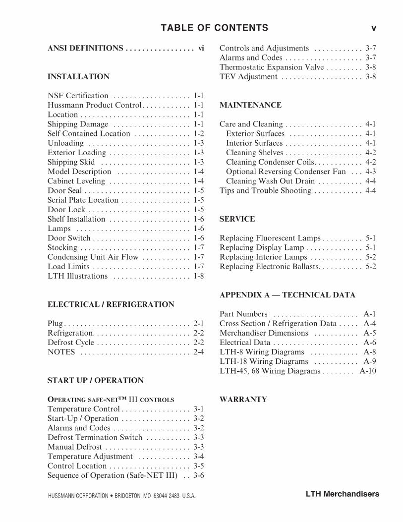
ANSI DEFINITIONS . . . . . . . . . . . . . . . . . vi
INSTALLATION
NSF Certification . . . . . . . . . . . . . . . . . . . 1-1Hussmann Product Control . . . . . . . . . . . . 1-1Location . . . . . . . . . . . . . . . . . . . . . . . . . . . 1-1Shipping Damage . . . . . . . . . . . . . . . . . . . 1-1Self Contained Location . . . . . . . . . . . . . . 1-2Unloading . . . . . . . . . . . . . . . . . . . . . . . . . 1-3Exterior Loading . . . . . . . . . . . . . . . . . . . . 1-3Shipping Skid . . . . . . . . . . . . . . . . . . . . . . 1-3Model Description . . . . . . . . . . . . . . . . . . 1-4Cabinet Leveling . . . . . . . . . . . . . . . . . . . . 1-4Door Seal . . . . . . . . . . . . . . . . . . . . . . . . . . 1-5Serial Plate Location . . . . . . . . . . . . . . . . . 1-5Door Lock . . . . . . . . . . . . . . . . . . . . . . . . . 1-5Shelf Installation . . . . . . . . . . . . . . . . . . . . 1-6Lamps . . . . . . . . . . . . . . . . . . . . . . . . . . . . 1-6Door Switch . . . . . . . . . . . . . . . . . . . . . . . . 1-6Stocking . . . . . . . . . . . . . . . . . . . . . . . . . . . 1-7Condensing Unit Air Flow . . . . . . . . . . . . 1-7Load Limits . . . . . . . . . . . . . . . . . . . . . . . . 1-7LTH Illustrations . . . . . . . . . . . . . . . . . . . 1-8
ELECTRICAL / REFRIGERATION
Plug . . . . . . . . . . . . . . . . . . . . . . . . . . . . . . . 2-1Refrigeration . . . . . . . . . . . . . . . . . . . . . . . . 2-2Defrost Cycle . . . . . . . . . . . . . . . . . . . . . . . 2-2NOTES . . . . . . . . . . . . . . . . . . . . . . . . . . . 2-4
START UP / OPERATION
Operating safe-net™ III cOntrOls
Temperature Control . . . . . . . . . . . . . . . . . 3-1Start-Up / Operation . . . . . . . . . . . . . . . . . 3-2Alarms and Codes . . . . . . . . . . . . . . . . . . . 3-2Defrost Termination Switch . . . . . . . . . . . 3-3Manual Defrost . . . . . . . . . . . . . . . . . . . . . 3-3Temperature Adjustment . . . . . . . . . . . . . 3-4Control Location . . . . . . . . . . . . . . . . . . . . 3-5Sequence of Operation (Safe-NET III) . . 3-6
Controls and Adjustments . . . . . . . . . . . . 3-7Alarms and Codes . . . . . . . . . . . . . . . . . . . 3-7Thermostatic Expansion Valve . . . . . . . . . 3-8TEV Adjustment . . . . . . . . . . . . . . . . . . . . 3-8
MAINTENANCE
Care and Cleaning . . . . . . . . . . . . . . . . . . . 4-1 Exterior Surfaces . . . . . . . . . . . . . . . . . . 4-1 Interior Surfaces . . . . . . . . . . . . . . . . . . . 4-1 Cleaning Shelves . . . . . . . . . . . . . . . . . . . 4-2 Cleaning Condenser Coils . . . . . . . . . . . . 4-2 Optional Reversing Condenser Fan . . . 4-3 Cleaning Wash Out Drain . . . . . . . . . . . 4-4Tips and Trouble Shooting . . . . . . . . . . . . 4-4
SERVICE
Replacing Fluorescent Lamps . . . . . . . . . . 5-1Replacing Display Lamp . . . . . . . . . . . . . . 5-1Replacing Interior Lamps . . . . . . . . . . . . . 5-2Replacing Electronic Ballasts . . . . . . . . . . . 5-2
APPENDIX A — TECHNICAL DATA
Part Numbers . . . . . . . . . . . . . . . . . . . . . A-1Cross Section / Refrigeration Data . . . . . A-4Merchandiser Dimensions . . . . . . . . . . . A-5Electrical Data . . . . . . . . . . . . . . . . . . . . . A-6LTH-8 Wiring Diagrams . . . . . . . . . . . . A-8LTH-18 Wiring Diagrams . . . . . . . . . . . A-9LTH-45, 68 Wiring Diagrams . . . . . . . . A-10
WARRANTY
TABLE OF CONTENTS v
HUSSMANN CORPORATION • BRIDGETON, MO 63044-2483 U.S.A. LTH Merchandisers

vi
REVISION HISTORY
Revision FSensor Location, Page 3-5, 3-6; Removed Type 2, Page 1-1; Added California Warning, Page 1-3; Removed Safe-NET 1 references, Section 2, New Part Numbers, Section 5, New Wiring Diagrams, Section A.
Revision EEliminate barcode from the front pageEliminate IR Logo from pages 24 (3-6), 25 (3-7), 27 (3-9), 52 (last page).Update revision letter (D to E, all pages with the revision) and the Date.Removed Picture of LED receptacles on Page 2-1; Changed LED and Fluorescent Electrical requirements on (left Column wording)
Revision D — December 2010Added Air Flow Drawing, Page, 1-2Added Model Description, Page, 1-3Added Serial Plate Location, Page 1-5Revised Stocking Illustrations, Page 1-7Added Sequence of Operation Diagram, Page 3-5Added Appendix A
Revision C — June 2009Added LTH-45 and LTH-68 modelsUpdated wiring diagramsAdded Safe-NET I codesAdded Safe-NET III information
Revision B — Added Safe-NET™Restructured manual; added Maintenance information
Revision A —Original Issue
P/N 0506146_F U.S. & Canada 1-800-922-1919 • Mexico 1-800-522-1900 • www.hussmann.com
* * * * * * * * * * * * * * * * * * * * * * * * * * ANSI Z535 .5 DEFINITIONS
• DANGER – Indicate[s] a hazardous situation which, if not avoided, will result in death or serious injury.
• WARNING – Indicate[s] a hazardous situation which, if not avoided, could result in death or serious injury.
• CAUTION – Indicate[s] a hazardous situation which, if not avoided, could result in minor or moderate injury.
• NOTICE – Not related to personal injury – Indicates[s] situations, which if not avoided, could result in damage to equipment.
�
�
�

P/N 0506146_F 1-1
LTH ManualHUSSMANN CORPORATION • BRIDGETON, MO 63044-2483 U.S.A. • WWW.HUSSMANN.COM
NSF CERTIFICATION
These merchandisers are manufactured to meet ANSI / National Sanitation Foundation (NSF® ) Standard #7 requirements. Proper installation is required to maintain certification. Near the serial plate, each case carries a label identifying the type of application for which the case was certified.
ANSI/NSF-7 Type I - Display Refrigerator / Freezer
Intended for 75°F / 55% RH Ambient Application
ANSI/NSF-7 - Display Refrigerator
Intended for Bulk Produce
HUSSMANN PRODUCT CONTROL
The serial number and shipping date of all equipment is recorded in Hussmann’s files for warranty and replacement part purposes. All correspondence pertaining to warranty or parts ordering must include the serial number of each piece of equipment involved. This is to ensure the customer is provided with the correct parts.
LOCATION
These merchandisers are designed for displaying products in air conditioned stores where temperature is maintained at or below the ANSI / NSF-7 specified level and relative humidity is maintained at or below 55%.
Recommended operating ambient temperature is between 65° F (18° C) with a maximum 55% relative humidity to 80 F (26° C) with a maximum 55% relative humidity.
Placing refrigerated merchandisers in direct sunlight, near hot tables or near other heat sources could impair their efficiency. Like other merchandisers, these self-contained units are sensitive to air disturbances. Air currents passing around merchandisers will seriously impair their operation. Do NOT allow air conditioning, electric fans, open doors or windows, etc. to create air currents around the case. LTH units in take air and exhaust air through the front of the case, and require no clearance space on top, at the back or either side.
Product should always be maintained at prop-er temperature. This means that from the time the product is received, through storage, preparation and display, the temperature of the product must be controlled to maximize the life of the product.
SHIPPING DAMAGE
All equipment should be thoroughly examined for shipping damage before and during unloading. This equipment has been carefully inspected at our factory. Any claim for loss or damage must be made to the carrier. The carrier will provide any necessary inspection reports and/or claim forms.
Apparent Loss or DamageIf there is an obvious loss or damage, it must be noted on the freight bill or express receipt and signed by the carrier’s agent; otherwise, carrier may refuse claim.
Concealed Loss or DamageWhen loss or damage is not apparent until after equipment is uncrated, retain all packing materials and submit a written response to the carrier for inspection, within 15 days.
INSTALLATION

P/N 0506146_F
1-2 Installation
U.S. & Canada 1-800-922-1919 • Mexico 1-800-522-1900 • WWW.HUSSMANN.COM
SELF CONTAINED (LOCATION)
Product should always be maintained at proper temperature. This means that from the time the product is received, through storage, prepa-ration and display, the temperature of the prod-uct must be controlled to maximize the life of the product.
Be sure to position self contained merchandisers properly.
SELF CONTAINED models have vented base panels to allow air circulation through the condensing unit.
Allow for a minimum 36 in. clearance in the front. Blocking or restricting air flow will adversely affect performance and may damage the refrigeration system.
36 in. 36 in. 36 in.
Air Intake
Air E xhaust
Front R ear
Zero Clearance at Sides and R ear
36 in. C learance at Front
(Plan View)
Air Intake
Air Intake
Front R ear
Zero Clearance at Sides and R ear
36 in. C learance at Front
(Plan View)
Air Intake
Air Intake
Front R ear
Zero Clearance at Sides and R ear
36 in. C learance at Front
(Plan View)
Air E xhaust
Air E xhaust
P/N 0506146_F 1-3
LTH ManualHUSSMANN CORPORATION • BRIDGETON, MO 63044-2483 U.S.A. • WWW.HUSSMANN.COM
UNLOADING
Unloading from Trailer:
Lever Bar (also known as a Mule, Johnson Bar, J-Bar, Lever Dolly, or Pry Lever)
Move the merchandiser as close as possible to its permanent location and remove all packaging. Check for damage before discarding packaging. Remove all separately packed accessories such as kits and shelves.
Improper handling may cause damage to the merchandiser when unloading. To avoid damage:
1. Do not drag the merchandiser out of the trailer. Use a Johnson bar (mule).
2. Use a forklift or dolly to remove the merchandiser from the trailer.
EXTERIOR LOADING
Do NOT walk on top of the merchandiser or damage to the merchandisers and serious personal injury could occur.
merchandisers are not structurally designed to support excessive external loading such as the weight of a person. Do not place heavy objects on the merchandiser.
SHIPPING SKID
Each merchandiser is shipped on a skid to protect the merchandiser’s base and to make positioning the case easier..
Remove the top of the crate and detach walls from each other. Lift crate from the skid. Unscrew the case from the skid. The merchandiser can now be lifted off the crate skid. Lift only at base of skid! Remove any braces and/or skids attached (blanket wrapped merchandiser may have skids).
DO NOT TILT MERCHANDISER ON ITS SIDE OR END WHEN REMOVING SKID.
Once the skid is removed, the merchandiser must be lifted —NOT PUSHED— to reposition. To remove the skid, remove screws attaching skid to the merchandiser.
Check floor where merchandisers are to be set to if it is a level area. Determine the highest part of the floor.
Do NOT stand or walk on top of merchandiser. Do not store items or flammable materials atop the unit.
This product may contain chemicals known to the State of California to cause cancer, birth defects, or other reproductive harm.
This warning is the result of the California State law known as the California Safe Drinking Water and Toxic Enforcement Act of 1986, which is commonly referred to as “Proposition 65.”
This warning does not mean that Hussmann products will cause cancer or reproductive harm, or is in violation of any product-safety standards or requirements. As clarified by the California State government, Proposition 65 can be considered more of a ‘right to know’ law than a pure product safety law. When used as designed, Hussmann believes that our products are not harmful. We provide the Proposition 65 warning to stay in compliance with California State law. It is your responsibility to provide accurate Proposition 65 warning labels to your customers when necessary. For more information on Proposition 65, please visit the California State government website.
For California Businesses:
P/N 0506146_F
1-4 Installation
U.S. & Canada 1-800-922-1919 • Mexico 1-800-522-1900 • WWW.HUSSMANN.COM
MODEL DESCRIPTION
LTH merchandisers are low temperature self- contained cabinets, designed for pre-packaged frozen food or products that require frozen temperatures for conservation.
Design features include:
• Self-closing glass doors • Electronic controls • CFC free-foam insulation • Lighted Sign (except LTH-8S) • Door lock • Cassette refrigeration system
Available options are:
• Reversing condenser fan motor • Buzzer alarm
CABINET LEVELING
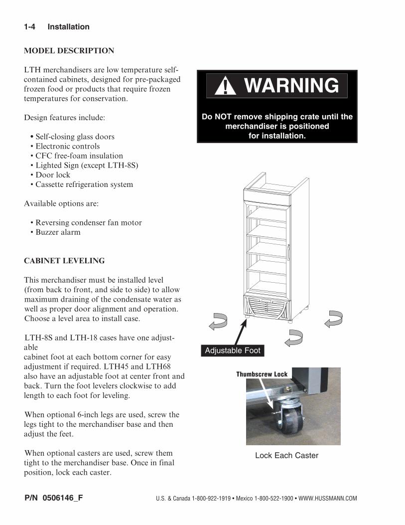
This merchandiser must be installed level (from back to front, and side to side) to allow maximum draining of the condensate water as well as proper door alignment and operation. Choose a level area to install case.
LTH-8S and LTH-18 cases have one adjust-able cabinet foot at each bottom corner for easy adjustment if required. LTH45 and LTH68 also have an adjustable foot at center front and back. Turn the foot levelers clockwise to add length to each foot for leveling.
When optional 6-inch legs are used, screw the legs tight to the merchandiser base and then adjust the feet.
When optional casters are used, screw them tight to the merchandiser base. Once in final position, lock each caster.
Adjustable Foot
Lock Each Caster
Thumbscrew Lock
Do NOT remove shipping crate until the merchandiser is positioned
for installation.

P/N 0506146_F 1-5
LTH ManualHUSSMANN CORPORATION • BRIDGETON, MO 63044-2483 U.S.A. • WWW.HUSSMANN.COM
Adjust Door Closing Torque
DOOR SEAL
Check that hinge doors close automatically by opening the door 45 degrees and releasing. Ensure door closes and gasket seals door shut. To adjust the torque applied to the hinged door:
1. Place a wrench on each of the two lower support nuts located at the bottom hinge.
2. Loosen the lower nut while holding the upper nut in place.
3. Torque is increased or decreased by rotat-ing the top nut. After adjustments are made, tighten the bottom nut while holding the upper nut in place. Torque bottom nut to a minimum of 20 ft-lb.
SERIAL PLATE LOCATION
The serial plate is located at the interior left side of the merchandiser’s cabinet. It contains all pertinent information such as model, serial number, amperage rating, refrigerant type and charge.
DOOR LOCK
A door lock is standard on all doors. The key is tie-wrapped to the door handle at shipment.

P/N 0506146_F
1-6 Installation
U.S. & Canada 1-800-922-1919 • Mexico 1-800-522-1900 • WWW.HUSSMANN.COM
Shelves
Solid Shelf
NOTE:Do not move the SolidShelf at the front of case
Display Lamp with Cover Removed
Light Switch
Solid ShelfCase Front
Door Lock
SHELF INSTALLATION
After the cabinet is leveled, the shelves may be installed. Wire shelves are adjustable. Shelf spacing can be adjusted by positioning the shelf clips according to individual loading requirements.
LTH-8S merchandisers have three movable wire shelves and one solid shelf. LTH-18, LTH-45 and LTH-68 merchandisers have four movable wire shelves and one solid shelf, per door
NOTE: The movable wire shelves may be reversed so that the wire shelf lip is positioned in the front as a product stop.
LAMPS
This merchandiser has a light switch that operates both the display and the interior lamps. Interior lamps are equipped with a plastic shield for safety.
DOOR SWITCH
The merchandiser’s door switch controls the evaporator fan motor. The switch shuts the evaporator fan off when the door is opened. This reduces energy consumption and helps prevent product temperatures from increasing from the door being opened and closed.
Never Block Air Opening
Door Switch

P/N 0506146_F 1-7
LTH ManualHUSSMANN CORPORATION • BRIDGETON, MO 63044-2483 U.S.A. • WWW.HUSSMANN.COM
Load Limit for LTH-8S Merchandisers
Load Limit for LTH-18, LTH-45 and LTH-68 Merchandisers
No product within
4 inches of top
At no time should product be stocked: • Beyond the front of shelves • Near the air exhaust duct located at the top rear of case • Near or covering the front return air grille • Within four inches of the top of the cabinet (This space must be free of product and other materials.)
DO NOT LOAD CASE WITH WARM PRODUCT.
STOCKING
Product should NOT be placed in case until merchandiser is at proper operating tempera-ture. The LTH merchandisers must remain in operation for at least 24 hours before product may be loaded into case cabinet. Proper rota-tion of product during stocking is necessary to prevent product loss. Always bring the oldest product to the front and set the newest to the back.
Air exhAust And return grille must remAin open And free of obstruction At All times.
Do not allow product, packages, signs, etc. to block air exhaust or return grille. Do not use non-approved shelving, baskets, display racks, or any accessory that could hamper air cur-tain performance. do not stock product in the top four inches of lth cAses becAuse product will block the cold Air flow.
CONDENSING UNIT AIR FLOW
An optional reversing condenser fan is available for all LTH models. The condenser fan runs in reverse during the defrost cycle to clear the condenser coil of debris that was accumulated during the refrigeration cycle.
LOAD LIMITS
Product must be within designated load limit to ensure proper refrigeration and air curtain performance.
No product within
4 inches of top

P/N 0506146_F
1-8 Installation
U.S. & Canada 1-800-922-1919 • Mexico 1-800-522-1900 • WWW.HUSSMANN.COM
LTH-8S LTH-18 LTH-45 LTH-68

P/N 0506146_F 2-1
LTH ManualHUSSMANN CORPORATION • BRIDGETON, MO 63044-2483 U.S.A. • WWW.HUSSMANN.COM
PLUG
The plug cord is 9 ft long and is located on the right hand rear of the merchandiser. Disconnect power before servicing. LTH merchandisers require a dedicated electrical circuit with ground. 12AWG is the minimum sized acceptable wire.
• The LTH-8S and LTH-18 require a dedicat-ed 15 AMP/115V circuit with grounded wall receptacle (NEMA 5-15R).
• The LTH-45 requires a dedicated 15 AMP/208-230V circuit with a grounded wall receptacle (NEMA 6-15R).
• The LTH-68 requires a dedicated 20 AMP/208-230V circuit with a grounded wall receptacle (NEMA 6-20R).
• Always use a dedicated circuit with the amperage stated on the unit.
• Plug into an outlet designed for the plug.• Do not overload the circuit• Do not use long or thin extension cords.
Never use adapters.• If in doubt, call an electrician.
ELECTRICAL / REFRIGERATION
Nominal Minimum Maximum Voltage Voltage Voltage
120 108 132
208-230 188 253
— LOCK OUT / TAG OUT —To avoid serious injury or death from elec-trical shock, always disconnect the electrical power at the main disconnect when servicing or replacing any electrical component. This includes, but is not limited to, such items as doors, lights, fans, heaters, and thermostats.
ALWAYS CHECK THE SERIAL PLATE FOR COMPONENT AMPERES
Risk of Electric Shock. If cord or plug becomes damaged, replace only with
a cord and plug of the same type.
Merchandiser must be grounded.Do not remove the power supply cord ground.

P/N 0506146_F
2-2 Electrical / Refrigeration
U.S. & Canada 1-800-922-1919 • Mexico 1-800-522-1900 • WWW.HUSSMANN.COM
REFRIGERATION
Each LTH merchandiser have Safe-NET III controls.
All LTH merchandisers are equipped with a hermetic compressor. The condenser has a fin and tube construction. Cold discharge air flows from the top air duct on the back of the case. Air is returned through the bottom front return air grille.
DEFROST CYCLE
All LTH merchandisers require defrost cycles for proper operation. The defrost cycles are factory set.
Merchandisers are set to defrost three times each day. During defrost, the evaporator fans operate intermittently to clear any condensation
from the interior side of the door. Defrost is initiated by Safe-NET III control, and is ter-minated according to coil temperature. In the event the sensor does not terminate the defrost cycle, a fail-safe value is programmed to termi-nate on time.
All LTH merchandisers are factory set with three defrost cycles, every 8 hours.
With Safe-NET III, the defrost cycle is initiated at start-up and every 8 hours thereafter. If the power is interrupted, the defrost resets to this time. The defrost can be reset to a desired time by unplugging and restarting the merchandiser at the preferred time.
After the defrost cycle, evaporator fans are delayed from starting to prevent water from being blown out of the evaporator pan. Fans are also delayed during initial startup for approximately 10 minutes.
Note: To reduce accumulation of frost on the evaporator coil, the fans will cycle off with each door opening and back on as the door closes.
The evaporator fans also cycle ON and OFF during the defrost. The fans cycles for 10 seconds every two minutes. The fan cycles increase defrost efficiency.
Evaporator Fans
Safe-NET III Control
Safe-NET III Display

P/N 0506146_F 3-1
LTH ManualHUSSMANN CORPORATION • BRIDGETON, MO 63044-2483 U.S.A. • WWW.HUSSMANN.COM
START UP / OPERATIONOPERATING Safe-NET III CONTROLS
The Safe-NET III electronic temperature and defrost controller is located in the cassette compartment. The controller comes factory set at position #5 and is ready to go.
The front grille must be removed in order to access this control. To remove the grille, open the door and remove the two plastic screws and retainers on the top of the grille, then tilt out and lift up to remove.
When removing the grille for this operation or for condenser cleaning, care must be taken not to damage the display interface cable. It may be unplugged during this task.
The temperatures can be adjusted by rotating the knob counter-clockwise for a warmer set-point, or clockwise for a colder setpoint. The display shows the setpoint for a few seconds when changed, then reverts to showing the sensed temperatures in the merchandiser.
The adjustment knob allows the user to select a pre-configured cold setpoint, warm setpoint or any setpoint within this range. The adjust-ment knob is also configured with Off/On functionality to power off the controller. The off position shuts off the compressor only.
UNPLUG THE UNIT FOR SERVICE.
The top, or green, LED indicates the case is in refrigeration mode. The center, or yellow, LED indicates the case is in defrost mode. The bot-tom (red) LED indicates an alarm condition, such as merchandiser warming up because the door is not closed.
Safe-NET III Controller Location
Remove Plastic Screws
Unplug Interface Cable
Interface Cable Plug
Remove Plastic Screws
Safe-NET III Indicators
CompressorPowered on
GREEN
Defrost CycleYELLOW
AlarmRED
Off / On Position
Position #5
P/N 0506146_F
3-2 Start up / OperatiOn
U.S. & Canada 1-800-922-1919 • Mexico 1-800-522-1900 • WWW.HUSSMANN.COM
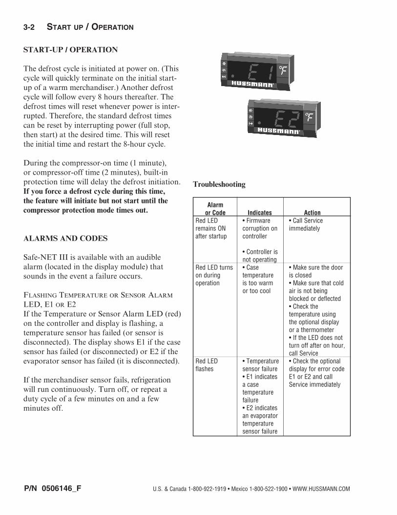
START-UP / OPERATION
The defrost cycle is initiated at power on. (This cycle will quickly terminate on the initial start-up of a warm merchandiser.) Another defrost cycle will follow every 8 hours thereafter. The defrost times will reset whenever power is inter-rupted. Therefore, the standard defrost times can be reset by interrupting power (full stop, then start) at the desired time. This will reset the initial time and restart the 8-hour cycle.
During the compressor-on time (1 minute), or compressor-off time (2 minutes), built-in protection time will delay the defrost initiation. If you force a defrost cycle during this time, the feature will initiate but not start until the compressor protection mode times out.
ALARMS AND CODES
Safe-NET III is available with an audible alarm (located in the display module) that sounds in the event a failure occurs.
flashing TemperaTure Or sensOr alarm leD, e1 Or e2If the Temperature or Sensor Alarm LED (red) on the controller and display is flashing, a temperature sensor has failed (or sensor is disconnected). The display shows E1 if the case sensor has failed (or disconnected) or E2 if the evaporator sensor has failed (it is disconnected).
If the merchandiser sensor fails, refrigeration will run continuously. Turn off, or repeat a duty cycle of a few minutes on and a few minutes off.
Troubleshooting
Alarm or Code Indicates ActionRed LED • Firmware • Call Serviceremains ON corruption on immediatelyafter startup controller • Controller is not operatingRed LED turns • Case • Make sure the door on during temperature is closedoperation is too warm • Make sure that cold or too cool air is not being blocked or deflected • Check the temperature using the optional display or a thermometer • If the LED does not turn off after on hour, call ServiceRed LED • Temperature • Check the optional flashes sensor failure display for error code • E1 indicates E1 or E2 and call a case Service immediately temperature failure • E2 indicates an evaporator temperature sensor failure
P/N 0506146_F 3-3
LTH ManualHUSSMANN CORPORATION • BRIDGETON, MO 63044-2483 U.S.A. • WWW.HUSSMANN.COM
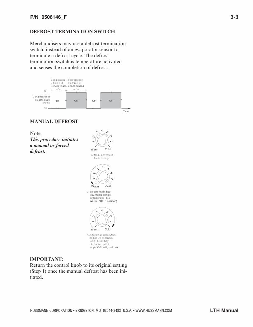
DEFROST TERMINATION SWITCH
Merchandisers may use a defrost termination switch, instead of an evaporator sensor to terminate a defrost cycle. The defrost termination switch is temperature activated and senses the completion of defrost.
MANUAL DEFROST
Note: This procedure initiates a manual or forced defrost.
IMPORTANT: Return the control knob to its original setting (Step 1) once the manual defrost has been ini-tiated.
On
OffTime
Off On Off On
Com pressor Off Tim e If Sensor Failed
Com pressor On Tim e If Sensor Failed
Com pressor or Refrigeration
Status
12
3 4 5
67
I I
Warm Cold
Rotate knob fully counterclockwise until it stops (full
2.
12
3 4 5
67
I I
Warm Cold
Note location of knob setting
1.
12
3 4 5
67
I I
Warm Cold
3.After 10 seconds, but before 20 seconds, rotate knob fully clockwise until it stops (full cold position)

P/N 0506146_F
3-4 Start up / OperatiOn
U.S. & Canada 1-800-922-1919 • Mexico 1-800-522-1900 • WWW.HUSSMANN.COM
TEMPERATURE ADJUSTMENT
1. Rotate the adjustment knob counter clock-wise for a warmer setpoint or clockwise for a colder setpoint.
2. While adjusting the temperature, the display shows the setpoint (cut out value). A few seconds after the temperature is set, the controller reverts to the sensed temperature in the merchandiser.
3. To verify merchandiser settings, turn the dial to warm and cold as shown above. Output readings should be within one degree of the temperatures shown above.
The control has protective settings to prevent short cycling of the compressor.
A. The compressor may run for up to 60 sec. after Step 2 is completed. Start the 10 sec. count down for Step 3, once the display is blank.
B. The defrost initiation may be delayed for up to 120 sec. after Step 3 is completed.
76
COLDWARM
12
43 5
Display - at Full Cold Model LTH
Display - at #1 Position Model LTH
76
COLDWARM
12
43 5
"OFF" PositionSafe-NET III ControlSet at Full Cold Position
Safe-NET III Control # 1 Position
P/N 0506146_F 3-5
LTH ManualHUSSMANN CORPORATION • BRIDGETON, MO 63044-2483 U.S.A. • WWW.HUSSMANN.COM
89
1011
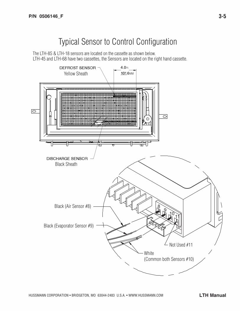
LTH-45 and LTH-68 have two cassettes, the Sensors are located on the right hand cassette.
Yellow Sheath
Black Sheath
Black (Air Sensor #8)
Black (Evaporator Sensor #9)
White(Common both Sensors #10)
Not Used #11
Typical Sensor to Control Configuration
MM
in.
The LTH-8S & LTH-18 sensors are located on the cassette as shown below.

P/N 0506146_F
3-6 Start up / OperatiOn
U.S. & Canada 1-800-922-1919 • Mexico 1-800-522-1900 • WWW.HUSSMANN.COM
Sequence of Operation — LTH Merchandisers
1 NOTE: The 65°C Version Controller includes a Parameter Code Number. This number indicates what program has been loaded into the controller. When the Controller is first powered up or is turned off and then back on a 2 digit Parameter Code Number will display for 3 seconds. Then the Self Check will Start.
1a. The Safe-NET Parameter Code is 50 for LTH-8S, LTH-45 and LTH-68. The Parameter Code is 75 for the LTH-18. If the case is warm at initial start-up, the defrost will be initiated and will terminate almost immediately. (Display will lock in cur-rent temperature when defrost is initiated.)
1b. If the case is cold (as if it is turned off and then back on), the defrost cycle will continue until the termination temperature is reached or the fail-safe time has expired.
2 The compressor will start 10 seconds after the power is applied.
3 The compressor will run for 10 minutes. Then, defrost will be initiated.
4 During defrost, the display will show the temperature before defrost, and it will continue to show this temperature for 1 hour. Compressor will turn back on once coil is defrosted.
5 The compressor will continue to run until it reaches its cut-out temperature (pull down).
6 The refrigeration cycle will continue until the next scheduled (8 hours) or demand defrost.
7 3 and 4 will repeat until power is interrupted.
NOTE: If power is interrupted, sequence will start at 4. Defrost will be initiated and the time to subsequent defrost will reset.
P/N 0506146_F 3-7
LTH ManualHUSSMANN CORPORATION • BRIDGETON, MO 63044-2483 U.S.A. • WWW.HUSSMANN.COM
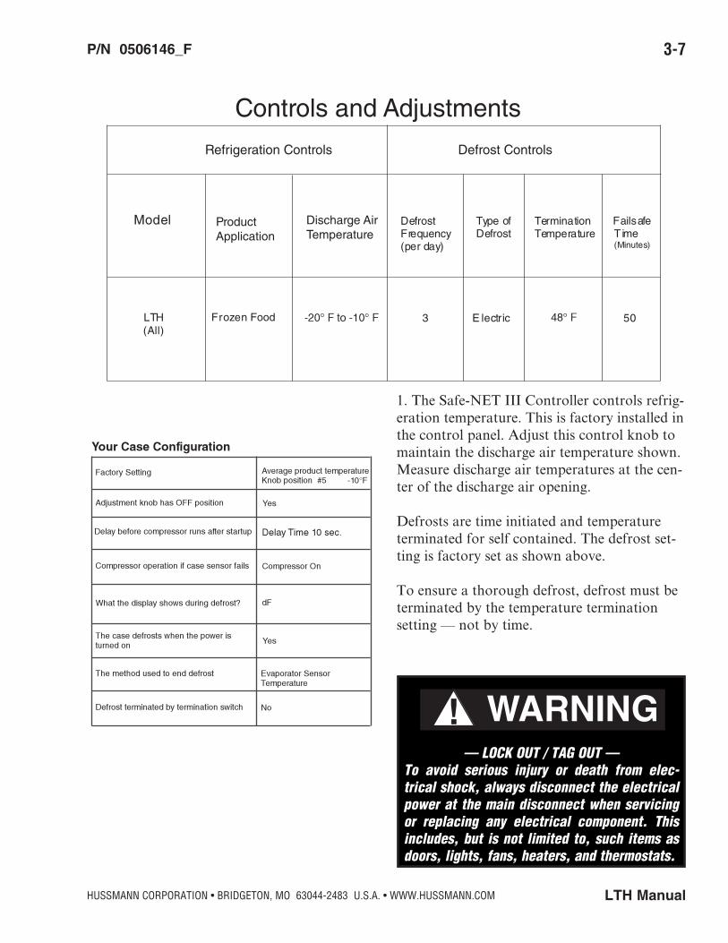
1. The Safe-NET III Controller controls refrig-eration temperature. This is factory installed in the control panel. Adjust this control knob to maintain the discharge air temperature shown. Measure discharge air temperatures at the cen-ter of the discharge air opening.
Defrosts are time initiated and temperature terminated for self contained. The defrost set-ting is factory set as shown above.
To ensure a thorough defrost, defrost must be terminated by the temperature termination setting — not by time.
Model Defrost Frequency (per day)
Type of Defrost
Termination Temperature
Failsafe T ime (Minutes)
3 E lectric 50LTH (All)
Frozen Food
Controls and Adjustments
Defrost ControlsRefrigeration Controls
Product Application
Discharge Air Temperature
— LOCK OUT / TAG OUT —To avoid serious injury or death from elec-trical shock, always disconnect the electrical power at the main disconnect when servicing or replacing any electrical component. This includes, but is not limited to, such items as doors, lights, fans, heaters, and thermostats.
P/N 0506146_F
3-8 Start up / OperatiOn
U.S. & Canada 1-800-922-1919 • Mexico 1-800-522-1900 • WWW.HUSSMANN.COM
THERMOSTATIC EXPANSION VALVE (TEV)
Each self contained merchandiser has its own evaporator coil and a pre-set thermostatic expansion valve (TEV). The TEV has been factory set at design conditions to provide the recommended performance.
Remove the fan panel to expose the thermostatic expansion valve.
TEV ADJUSTMENT
Expansion valves may be adjusted to fully feed the evaporator. Before attempting to adjust valves, make sure the evaporator is clear or only lightly covered with frost, and the merchandiser is within 10°F of its expected operating temperature.
Adjust the valve as Follows:
a. Attach a probe to the suction line near the expansion valve bulb.
b. Obtain a pressure reading from the factory installed Schraeder valve. Convert the pres-sure reading to a saturated temperature for the refrigerant.
Temperature (b) minus Temperature (a) is the superheat. The valve should be adjusted so that the greatest difference between the two temperatures is 3°F to 5° F.
Make adjustments of no more than 1/2 turn of the valve stem at a time and wait for at least 15 minutes before rechecking the probe temperature and making further adjustments.

P/N 0506146_F 4-1
LTH ManualHUSSMANN CORPORATION • BRIDGETON, MO 63044-2483 U.S.A. • WWW.HUSSMANN.COM
CARE AND CLEANING
Long life and satisfactory performance of any equipment is dependent upon the care it receives. To ensure long life, proper sanita-tion and minimum maintenance costs, this unit should be thoroughly cleaned, all debris removed and the interiors washed down. Cleaning often will control or eliminate odor buildup. Frequency of cleaning is dependent on usage and local health requirements.
Exterior Surfaces
The exterior surfaces must be cleaned with a mild detergent and warm water to protect and maintain their attractive finish.
Never use abrasive cleaNers or scouriNg pads. Never use caustic soda, keroseNe, gasoliNe, thiNNer, solveNts, detergeNts, acids, chemicals or abrasives. do Not use ammoNia-based cleaNers oN acrylic parts.
Interior Surfaces
do Not use ammoNia-based products to cleaN light shields. Never use abrasive cleaNsers or scouriNg pads.
The interior surfaces may be cleaned with most domestic detergents and sanitizing solutions with no harm to the surface. Always read and follow the manufacturer’s instructions when using any cleaning product.
Do NOT Use:• Abrasive cleansers and scouring pads, as
these will mar the finish.• Coarse paper towels on coated glass.• Ammonia-based cleaners on acrylic parts.• A hose on lighted shelves or submerge the
shelves in water.• Solvent, oil or acidic based cleaners on any
interior surfaces.• A hose on rail lights, canopy lights or any
other electrical connection.
Do:• First turn off refrigeration, then disconnect
electrical power.• Remove product and loose debris.• Thoroughly clean all surfaces with soap
and hot water. do Not use steam or high water pressure hoses to wash the iNte-rior. These desTroy merchandiser’s sealing causing leaks and poor perfor-mance.
• Take care to minimize direct contact between fan motors and cleaning or rinse water.
• Rinse with hot water, but do NOT flood. • Allow merchandiser to dry before resuming
operation.• Wipe down lighted shelves with a damp
sponge or cloth so that water does not enter the light channel. do Not use a hose or submerge shelves iN water.
• After cleaning is completed, restore power and turn on the merchandiser.
MAINTENANCE
Do not use HOT water on COLD glass surfaces. This can cause the glass to shatter and could result in personal injury. Allow glass fronts, ends and service doors to warm before apply-ing hot water.
To reduce the risk of fire, electrical shock or injury when cleaning this merchandiser:
• Unplug the merchandiser before cleaning;• Keep all liquids away from electrical and elec-
tronic components;• Do not use any mechanical device or other
means to speed the defrost process, except as recommended by the manufacturer.

P/N 0506146_F
4-2 Maintenance
U.S. & Canada 1-800-922-1919 • Mexico 1-800-522-1900 • WWW.HUSSMANN.COM
Cleaning Shelves
Shelves and shelf clips are easily removed for cleaning the interior as well as the shelves themselves
Cleaning Condenser Coils
To maintain peak operating efficiency, the coil should be cleaned at least once each month. A dirty coil slows product cooling significantly and increases energy consumption by as much as 20%. Dirt buildup on coils can also cause the compressor to lock up damaging the con-denser unit.
• Remove screws on top of each side of the louvered from grille, then lift off the grille.
Detach Safe-NET I electrical wire harnesses. The harnesses are located behind the Safe-NET I controller. The power/relay harness on the left has an eight-slot connector. The sensor cable harness on the right has a four-slot con-nector. When re-installing, be sure to plug this harness in the bottom four-slot connection, not the top connection.
Next, detach the merchandiser’s electrical wire harness located on the right hand side near the coil. For Safe-NET III, detach the interface cable to the display.
Remove Screws at Top of Grille (LTH-18 shown)
Disconnect Safe-NET I Harnesses
Product will be degraded and may spoil if allowed to sit
in a non-refrigerated area.
Unplug Power Harness
Power/Relay Cable Sensor Cable
Unplug Safe-NET III Interface Cable
Interface Cable Plug
(Connected on the top connector)

P/N 0506146_F 4-3
LTH ManualHUSSMANN CORPORATION • BRIDGETON, MO 63044-2483 U.S.A. • WWW.HUSSMANN.COM
Remove the two screws securing refrigeration unit cassette in place.
Use the center black bar to pull the refrigera-tion unit’s cassette forward to access the coils.
use oNly the ceNter bar to pull out the cassette. pulliNg oN refrigeratioN liNes or other parts will cause damage to the refrigeratioN uNit.
Use a soft hand brush attachment on a vacu-um to remove accumulated dust and debris.
Consult an authorized service technician if more extensive cleaning is needed.
If the refrigeration unit is damaged, it can be replaced with a new cassette.
Optional Reversing Condenser Fan
If your merchandiser is equipped with the optional reversing condenser fan, you may notice the condenser fan running during the defrost cycle. This is normal in this applica-tion. The purpose of reversing the air direction during defrost is to remove lint and dust that accumulates on the condenser fin surfaces during the refrigeration cycle. This feature reduces the need to clean the condenser manually, and increases compressor life because of lower condensing temperatures.
For prompt service when contacting the factory, be sure to have the case model and
serial number from the case serial plate.
IMPORTANTINFORMATION
Use Center Bar to Pull Cassette
Remove Screws Holding Cassette
Center Bar
— LOCK OUT / TAG OUT —To avoid serious injury or death from elec-trical shock, always disconnect the electrical power at the main disconnect when servicing or replacing any electrical component. This includes, but is not limited to, such items as doors, lights, fans, heaters, and thermostats.

P/N 0506146_F
4-4 Maintenance
U.S. & Canada 1-800-922-1919 • Mexico 1-800-522-1900 • WWW.HUSSMANN.COM
Cleaning the Wash Out Drain
The wash out drain is located behind the refrigeration cassette and can be cleaned with water and wiped with a soft cloth. Ensure drain is unobstructed before replacing cassette.
The washout drain flows into an auxiliary waste line.
Next remove the auxiliary waste line cap to drain any excess water. Place a dry towel over the line to absorb water.
Replace cap, cables and cassette.
TIPS AND TROUBLESHOOTING
There are a few simple things to check before calling for service:
1. Product not cold? Refrigeration unit requires 24 hours at initial startup to cool down to operating temperature with No product loaded in merchandiser. Ask when merchandiser was stocked, and what the usage has been. It may take 30 minutes or more for product to chill following stocking.
2. Check the door and door seal for air leaks.
3. Power Supply: Is the unit plugged in? Is there power to the unit?
4. Location What are the ambient conditions—
temperature and humidity, direct sun, nearby source of heat, such as oven or grill? Is the unit level? Has the unit been moved recently?
5. Shelves and Stocking Are the standard shelves in the correct places? Is the product stocked properly? Is the bottom shelf at the proper location?
6. Confirm that the defrost schedule is properly set using Safe-NET I.
Check for Safe-NET error messages.
Auxiliary Waste Line
For prompt service when contacting the factory, be sure to have the case model and
serial number from the case serial plate.
IMPORTANTINFORMATION
Replace Cap, Cables and Cassette
Cap
Cable
Wash Out Drain
Drain

P/N 0506146_F 5-1
LTH ManualHUSSMANN CORPORATION • BRIDGETON, MO 63044-2483 U.S.A. • WWW.HUSSMANN.COM
REPLACING FLUORESCENT LAMPS
Fluorescent lamps have a plastic shield. When the lamp is replaced, keep the lamp shield to install over the new lamp..
The switch under the display lamp cover oper-ates both the display lamp and interior lamps.
REPLACING DISPLAY LAMP
Disconnect power to the merchandiser. Remove plastic pins attaching the display lamp panel. There are three pins at the bottom of the display cover and two on top of the display panel.
Remove the merchandiser’s display cover panel and change out the lamp. Replace the display panel cover.
SERVICE
Plastic Shield
FluorescentLamp
Remove Plastic Pins Attaching Display Lamp
Display Cover Panel Removed
Remove Plastic Pins Attaching Display Lamp
Pin
— LOCK OUT / TAG OUT —To avoid serious injury or death from elec-trical shock, always disconnect the electrical power at the main disconnect when servicing or replacing any electrical component. This includes, but is not limited to, such items as doors, lights, fans, heaters, and thermostats.

P/N 0506146_F
5-2 Service
U.S. & Canada 1-800-922-1919 • Mexico 1-800-522-1900 • WWW.HUSSMANN.COM
REPLACING INTERIOR LAMPS
LTH merchandisers have interior case lamps. The lamps are protected by a clear, plastic shield. Remove the shield to replace lamp. Wedge a small putty knife at the top rear of the lamp, then carefully loosen the shield from the side of the merchandiser.
Once the shield is out of rear track, the lamp shield can be removed from the merchandiser. Remove lamp shield and change out lamp. Replace lamp shield at bottom corner bracket first.
For LEDs, follow the same steps to remove the shield. Then pull out the LED fixture respecting the fixture position. Next, bow lamp shield and replace shield into top corner bracket. Smooth shield to ensure a good replacement fit for the lamp shield.
REPLACING ELECTRONIC BALLASTS
The electronic ballast or LED power supply for the LTH-8S is located on the refrigeration cassette. This ballast operates the interior lamp.
The electronic ballast or LED power supply for the LTH-18, LTH-45 and LTH-68 is locat-ed on the top of the merchandiser under a sheet metal enclosure. (LTH-68 shown.)
To access the ballast or LED power supply, the protective enclosure is removed by remov-ing screws as shown below.
Wedge Putty Knife at Top Rear of Display Lamp
Bow Shield to Replace
Remove Shield from Display Lamp

P/N 0506146_F 5-3
LTH ManualHUSSMANN CORPORATION • BRIDGETON, MO 63044-2483 U.S.A. • WWW.HUSSMANN.COM
Appendix A — TechnicAl dATA A-1
Models LTH8S LTH-18 LTH-45 LTH-68Standard PartsDescription Part NumberPower Cord (NEMA 5-15P) 19S216 X XPower Cord (NEMA 6-15P) 508528 XPower Cord (NEMA 6-20P) 1804385 XDoor Switch (fans) 03S121 X X X XLight Switch 1801241 X X X XDefrost Sensor (Yellow) 1.5MM 0509123 X X X XAir Sensor (Black) 1.5MM 0509122 X X X XSafe-Net III Controller 65C 0524118 X X X
Safe-Net III Display (F°) 65C 1H59052001 X X X XSafe-Net III Display Interface Cable 1M 0509783 X X X XSafe-Net IIIControl Harness 0513058 XSafe-Net IIIControl Harness 0507356 XSafe-Net IIIControl Harness 0510339 X XCompressor Relay (T92P11A22-120) 1804291 X XCompressor Relay (T92P11A22-240) 0518447 X XHeater Relay (T92P7A22-240) 1804241 X XTime Relay TGC2030SC2J 0509498 X XPilaster Strip (30") 0501242 XPilaster Strip (42") 0501240 X X XShelf Clips (insert into pilaster strips) 0403363 X X X XFan Delay Thermostat 1701540 X X X XDefrost Heater Limit Thermostat 0344662 X X X XWire Shelf (White) 15.5 X 19.625 0506952 XWire Shelf (White) 22 X 24.5 1201584 X XWire Shelf (White) 22 X 22.688 0506348 X XInterior Light Cover 0507791 XInterior Light Cover 0506054 X X XTop Hinge Cover 0506914 XFeet (Adjustable) 1005319 X X X XLamp Shield 0509372 XLamp Shield 1804590 XLamp Shield 1004377 X XLamp (F25T8/SPX41 RS GE) 1801494 XLamp (T5 FQ54W/840 HO) 1804587 XLamp (FO32/841 32W 1803337 X XLight Harness (w/ Lamp holders) 0507004 XLight Harness (w/ Lamp holders) 0509570 X XLamp Holder 0506517 XLamp Cap 0506516 XAssy Lens Mullion 0510340 X X
Safe-Net III Controller 65C 0551127 X
P/N 0506146_F
5-4 Service
U.S. & Canada 1-800-922-1919 • Mexico 1-800-522-1900 • WWW.HUSSMANN.COM
A-2 Appendix A — TechnicAl dATA
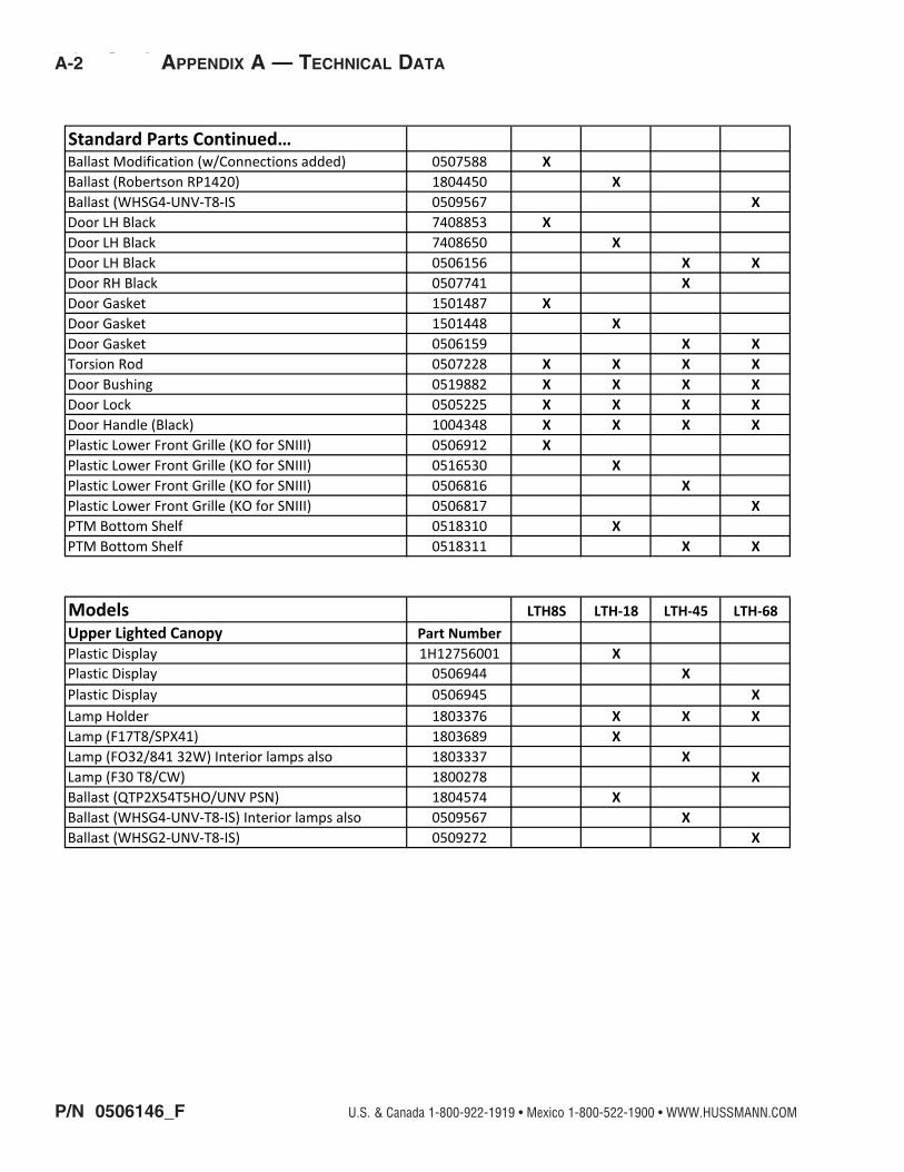
Standard Parts Continued…Ballast Modification (w/Connections added) 0507588 XBallast (Robertson RP1420) 1804450 XBallast (WHSG4-UNV-T8-IS 0509567 XDoor LH Black 7408853 XDoor LH Black 7408650 XDoor LH Black 0506156 X XDoor RH Black 0507741 XDoor Gasket 1501487 XDoor Gasket 1501448 XDoor Gasket 0506159 X XTorsion Rod 0507228 X X X XDoor Bushing 0519882 X X X XDoor Lock 0505225 X X X XDoor Handle (Black) 1004348 X X X XPlastic Lower Front Grille (KO for SNIII) 0506912 XPlastic Lower Front Grille (KO for SNIII) 0516530 XPlastic Lower Front Grille (KO for SNIII) 0506816 XPlastic Lower Front Grille (KO for SNIII) 0506817 XPTM Bottom Shelf 0518310 XPTM Bottom Shelf 0518311 X X
Models LTH8S LTH-18 LTH-45 LTH-68Upper Lighted Canopy Part NumberPlastic Display 1H12756001 XPlastic Display 0506944 XPlastic Display 0506945 XLamp Holder 1803376 X X XLamp (F17T8/SPX41) 1803689 XLamp (FO32/841 32W) Interior lamps also 1803337 XLamp (F30 T8/CW) 1800278 XBallast (QTP2X54T5HO/UNV PSN) 1804574 XBallast (WHSG4-UNV-T8-IS) Interior lamps also 0509567 XBallast (WHSG2-UNV-T8-IS) 0509272 X

P/N 0506146_F 5-5
LTH ManualHUSSMANN CORPORATION • BRIDGETON, MO 63044-2483 U.S.A. • WWW.HUSSMANN.COM
Appendix A — TechnicAl dATA A-3
Refrigeration Part NumberCompressor (Embraco NT2178GKV) 1H12397 XCompressor (NT2192GKV) 2000588 XCompressor (NT2178GK) 0507909 XCompressor (NJ2212GK) 0507805 XCondenser 1H12549 XCondenser (On LTH45 RH Cassette) 2100214 X X XCondenser (On LTH45 LH Cassette) 2100213 X XCondenser Fan Motor 0508069 XCondenser Fan Motor 1700502 XCondenser Fan Motor Assy (Motor,Blade & Mtg Brkt) 0508557 X XCondenser Fan Motor 1800566 X XCondenser Fan Blade 0501428 XCondenser Fan Blade 0500354 X X XEvaporator Fan Motor Assy (Motor,Blade, & Brkt) 0506136 X XEvaporator Fan Blade (FV600CW30P3B) 0501426 X X X XEvaporator Fan Motor (SSC B138 JHEM1) 1804554 X XEvaporator Fan Motor Assy (Motor,Blade, & Brkt) 0508113 XEvaporator Fan Motor 0510149 X XEvaporator Fan Motor Assy (Motor,Blade, & Brkt) 0507900 XEvaporator Coil 1H12309 XEvaporator Coil 2200182 XEvaporator Coil 0507584 XEvaporator Coil 0507382 XAccumulator 1701752 X X X XTXV (Sweat)R404A TUB#4 0509121 XTXV (Sweat)R404A EXPT52 MOD 068Z3414 1701366 XTXV (Sweat)R404A TUB orifice#5 068U3371 0510392 XFilter Drier (Sporlan C-032S) 1701751 X X XDrier (Danfoss 023Z5129) 0510867 XCondenser Gasket 1H13191 XCondenser Gasket 1501473 XCondenser Gasket 0508101 XCondenser Gasket 0507803 XEvaporator Gasket 0506925 XEvaporator Gasket 1501343 XEvaporator Gasket 0508100 XEvaporator Gasket 0507806 XCRO (CRO-4-0/50) 0518905 X
X

P/N 0506146_F
5-6 Service
U.S. & Canada 1-800-922-1919 • Mexico 1-800-522-1900 • WWW.HUSSMANN.COM
Heaters Part NumberDefrost Heater 1H13190 XDefrost Heater 1804360 XDefrost Heater 0507931 XDefrost Heater 0507383 XDoor Frame AS Heater 0507786 XDoor Frame AS Heater 1804541 XDoor Frame AS Heater 0507631 X XCase perimeter AS Heater 1804602 XCase perimeter AS Heater 1804539 XCase perimeter AS Heater (2) 0507630 X X
Sheel Metal Replacement Parts Painted All these part numbers below are painted assembliesBottom Solid Shelf Assy 7408890 XBottom Solid Shelf Assy 7408686 XBottom Solid Shelf Assy LH 0506441 X XBottom Solid Shelf Assy RH 0507394 X XBottom Solid Shelf Assy Center 0508065 XBottom Shelf Cover (Stainless Steel) 0507863 XBottom Shelf Cover (Stainless Steel) 0506511 XBottom Shelf Cover LH (Stainless Steel) 0507599 X XBottom Shelf Cover RH (Stainless Steel) 0507587 X XBottom Shelf Cover Center (Stainless Steel) 0508067 XDoor Hinge Lower 0521105 X X X* *Door Hinge Lower 0510152 X** X**Hinge Plate Upper Assy (w/ pin) 0508176 XDoor Hinge Assy Upper 0505093 X X XDoor Lock Bracket 0494798 X X X X* (1) On LTH45 for LH Dr & (1) on LTH68 for LH Dr**(1) On LTH-45 for RH Door & (2) on LTH68 for Center & RH Dr.
Appendix A — TechnicAl dATA A-4
P/N 0506146_F 5-7
LTH ManualHUSSMANN CORPORATION • BRIDGETON, MO 63044-2483 U.S.A. • WWW.HUSSMANN.COM
A-5 Appendix A — TechnicAl dATA
Dim ensionsExterior Interior (useable)
1/2 in. for door handle**Note: Overall height includes 1 1/2 in. for leveling pods
Electrical
M odel Doors Refrig.Cu. Ft. Capacity.
5/8 5/8 5/8 5/8 5/8 3/4
3/4
3/4
3/4 1/2
1/2
1/8
13/16 1/4
3/8 3/8
1/4
**
*Estim ated energy consum ption for optional LEDs
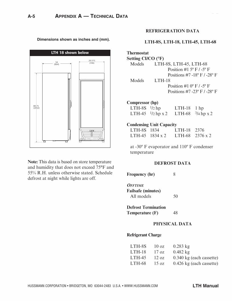
REFRIGERATION DATA
LTH-8S, LTH-18, LTH-45, LTH-68
ThermostatSetting CI/CO (°F) Models LTH-8S, LTH-45, LTH-68 Position #1 5º F / -5º F Positions #7 -18º F / -28º F Models LTH-18 Position #1 0º F / -5º F Positions #7 -23º F / -28º F
Compressor (hp) LTH-8S 1/2 hp LTH-18 1 hp LTH-45 1/2 hp x 2 LTH-68 3/4 hp x 2
Condensing Unit Capacity LTH-8S 1834 LTH-18 2376 LTH-45 1834 x 2 LTH-68 2376 x 2
at -30º F evaporator and 110º F condenser temperature
DEFROST DATA
Frequency (hr) 8
Offtime Failsafe (minutes) All models 50 Defrost TerminationTemperature (F) 48
PHYSICAL DATA
Refrigerant Charge LTH-8S 10 oz 0.283 kg LTH-18 17 oz 0.482 kg LTH-45 12 oz 0.340 kg (each cassette) LTH-68 15 oz 0.426 kg (each cassette)
Dimensions shown as inches and (mm).
Note: This data is based on store temperature and humidity that does not exceed 75°F and 55% R.H. unless otherwise stated. Schedule defrost at night while lights are off.

P/N 0506146_F
5-8 Service
U.S. & Canada 1-800-922-1919 • Mexico 1-800-522-1900 • WWW.HUSSMANN.COM
Appendix A — TechnicAl dATA A-6
Dim ensionsExterior Interior (useable)
1/2 in. for door handle**Note: Overall height includes 1 1/2 in. for leveling pods
Electrical
M odel Doors Refrig.Cu. Ft. Capacity.
5/8 5/8 5/8 5/8 5/8 3/4
3/4
3/4
3/4 1/2
1/2
1/8
13/16 1/4
3/8 3/8
1/4
**
*Estim ated energy consum ption for optional LEDs
Dim ensionsExterior Interior (useable)
1/2 in. for door handle**Note: Overall height includes 1 1/2 in. for leveling pods
Electrical
M odel Doors Refrig.Cu. Ft. Capacity.
5/8 5/8 5/8 5/8 5/8 3/4
3/4
3/4
3/4 1/2
1/2
1/8
13/16 1/4
3/8 3/8
1/4
**
*Estim ated energy consum ption for optional LEDs
LTH — Dimensions
LTH — Electrical Data

P/N 0506146_F 5-9
LTH ManualHUSSMANN CORPORATION • BRIDGETON, MO 63044-2483 U.S.A. • WWW.HUSSMANN.COM
Electrical Data
Note: These are rated values for individual components and should not be added together to determine total merchandiser electrical load.
Evaporator Fans 115V, 60Hz Standard for LTH-8S/18, 208-230V for LTH-45/68 LTH-8S LTH-18 LTH-45 LTH-68
Number of Motors 1 2 4 4
Amperes 0.4 0.8 1.2 1.2
Watts 16 32 120 120
Condensing Unit (115V, 1Ph, 60Hz) Standard for LTH 8S/18, 208-230V for LTH 45/68 Compressor LRA 56 45 59.8 59.8
Compressor RLA 10.5 10.2 12 12
Product Data
LTH-8S Interior Volume (Cu Ft/Case) 10.7 ft3 /case (301.57 liters /case)
LTH-18 Interior Volume (Cu Ft/Case) 22 ft3 /case (622.97 liters /case)
LTH-45 Interior Volume (Cu Ft/Case) 41.1 ft3 /case (1163.7 liters /case)
LTH-68 Interior Volume (Cu Ft/Case) 63.97 ft3 /case (1811.34 liters /case)
ESTIMATED SHIPPING WEIGHT 2
Case LTH-8S 310 lb (141kg)
LTH-18 535 lb (243kg)
LTH-45 1014 lb (460kg)
LTH-68 1036 lb (470kg)
2 Actual weights will vary according to optional kits included.
A-7 Appendix A — TechnicAl dATA

P/N 0506146_F
5-10 Service
U.S. & Canada 1-800-922-1919 • Mexico 1-800-522-1900 • WWW.HUSSMANN.COM
LTH-8S
WARNINGAll components must have mechanical ground, and the merchandiser must be grounded.
Circled Numbers = Parts List Item NumbersR = Red Y = Yellow G = Green BL = Blue BK = Black W = White
= 120V Power = 120V Neutral = Field Ground = Case Ground
Appendix A — Wiring diAgrAms A-8
GND
DIODE
HEATED GLASS
FRAME HEATER
LINE1
LINE2
COMP
NA
PHAS
E
FAN
PHAS
E
THERMOSTATSENSORAIR TEMP
HEAT
ER
2 M DISPLAY1 2 3 4 5 6 7
8 91011
SERIALHACCP
LINKPROGKEY
BLACK SHEATH
SAFENET III CONTROL
YELLOW SHEATH
BK BK W W
THERMOSTATSENSOR TEMP
DEFROST
3
21
5
4 14
2C
RS
0 1
8 43 7
6 2
NEMA5-15 P
115 V60HZ1HP
GRD
BK Y
BK
BK
WLIGHTSWITCH
DOOR SWITCH
BALLASTLAMP
W
OPTIONAL HEATERCABINET HEATER
BK
BK
W
W
Y
BK
FAN DELAY EVAPORATOR FAN
T-LIMIT
HEATER DEFROST
WBK
CONDENSER FAN
COMPRESSOR
B BK R BK BL W BK
W BK0508092_C
ELECTRIC SPECSMODEL: LTH8SVOLTAGE: 115 VFRECUENCY: 60 HZCOMPRESSOR: NT2178GK EMBRACO
WARNINGUNPLUG THE EQUIPMENT BEFORE SERVICING.
ADVERTENCIA:DESCONECTAR EL EQUIPO ANTES DE HACER CUALQUIERREPARACIÓN, PARA EVITAR ALGUN DAÑO.
NCCOM
NO
NCCOMNO
GND
POWERSUPPLY
LEDLED OPTION KIT

P/N 0506146_F 5-11
LTH ManualHUSSMANN CORPORATION • BRIDGETON, MO 63044-2483 U.S.A. • WWW.HUSSMANN.COM
A-9 Appendix A — Wiring diAgrAms
LTH-18
WARNINGAll components must have mechanical ground, and the merchandiser must be grounded.
Circled Numbers = Parts List Item NumbersR = Red Y = Yellow G = Green BL = Blue BK = Black W = White
= 120V Power = 120V Neutral = Field Ground = Case Ground
DEFROST RELAY
HEATED GLASS
DIODE
BALLAST
INTERIOR LAMP
LIGHT SWITCH
SIGN LAMP
Y
DOOR PERIMETER HEATER
INTERIOR LAMP
BALLAST
COMPRESSORRELAY
FAN DELAY
DOOR SWITCH
EVAPORATORFANS
BKW
DEFROST HEATER
W
BK
BK
FRAME HEATER
0 1
8 43 7
6 2
BK W
COMPRESSOR
CONDENSER FAN
BLBK BKB R
BK
LINE1
LIN
E2
CO
MP
PHA
SE
FA
N
PH
AS
E
THERMOSTATSENSORAIR TEMP
HEA
TER 2 M DISPLAY1 2 3 4 5 6 7
8 91011
SERIALHACCPLINK
PROGKEY
BLACK SHEATH
SAFENET III CONTROL
YELLOW SHEATH
BK BK W W
THERMOSTATSENSOR TEMP
DEFROST
0 1
8 43 7
6 2
3
21
5
4 14
2C
RS
INTERIOR LED
INTERIOR LEDPOWERSUPPLY
SIGN LED
W
W
W
W
BK
BK
BK
W
W
W
W
W
GRD
NCCOM
NO
NCCOM
NO
NC
COMNO
NC
COM
NO
NEMA5-15 P
115 V60HZ1HP
WARNINGUNPLUG THE EQUIPMENT BEFORE SERVICING
ADVERTENCIA:DESCONECTAR EL EQUIPO ANTES DE HACER CUALQUIERREPARACIÓN, PARA EVITAR ALGUN DAÑO.
ELECTRIC SPECSMODEL: LTH18VOLTAGE: 115 VFRECUENCY: 60 HZCOMPRESSOR: NT2192GKV EMBRACO
(MODELS WITH HEATED GLASS ONLY)
2402812_G
BK
LED OPTION KIT

P/N 0506146_F
5-12 Service
U.S. & Canada 1-800-922-1919 • Mexico 1-800-522-1900 • WWW.HUSSMANN.COM
LTH-45 and LTH-68
Appendix A — Wiring diAgrAms A-10
R BK
FAN DELAY
OVERLOAD
RELAY
BK
REVERSINGCONDENSER
FAN
DEFROST HEATER
DOOR SWITCHES
DEFROST RELAY
YEVAPORATOR
FANS
CASSETTE-RIGHT
14
35
FAN DELAY
W
W
W
BK
LIGHTSWITCH
CASSETTE-LEFT
W
LINE1
LINE2
COMP
NA
PHAS
E
FAN
PHAS
E
THERMOSTATSENSORAIR TEMP
HEAT
ER
2 M DISPLAY1 2 3 4 5 6 7
8 91011
SERIALHACCP
LINKPROGKEY
BLACK SHEATH
SAFENET III CONTROL
YELLOW SHEATH
BK BK W W
THERMOSTATSENSOR TEMP
DEFROST
DEFROST RELAY
4
0 1
8 43 7
6 2
ONLY WHEN REVERSINGCOND FAN IS USED
0 1
8 43 7
6 2
3
21
5
4 14
2C
RS
0 1
8 43 7
6 2
2
3
COMPRESSOR
RUN CAP.
OVERLOAD
RELAY
START CAP.
3
21
5
4 14
2C
RS
ONLY WHEN REVERSINGCOND FAN IS USED
208-230 V60HZ1HP
GRD
EVAPORATORFANS
DEFROST HEATER
BK
BK
BK
BK
TIME DELAY
1
2
3 OVERLOAD
5
BK
REVERSINGCONDENSER
FAN
0 1
8 43 7
6 2
COMPRESSOR
RUN CAP.
START CAP.
COMPRESSORRELAY
COMPRESSOR RELAY
NCCOMNO
NCCOMNO
NCCOMNO
NCCOMNO
NC
COMNO
NCCOMNO
NCCOMNO
NCCOMNO
ELECTRIC SPECSMODEL: LTH45VOLTAGE: 208-230 VFRECUENCY: 60 HZCOMPRESSOR: NT2178GK EMBRACO
WARNINGUNPLUG THE EQUIPMENT BEFORE TO MAKE ANYREPARATION TO AVOID ANY DAMAGEADVERTENCIA:DESCONECTAR EL EQUIPO ANTES DE HACER CUALQUIERREPARACIÓN, PARA EVITAR ALGUN DAÑO.B BK R BK BL W BK
DIODE
HEATER GLASS
FRAME HEATER
(MODELS WITH HEATED GLASS ONLY.)2 DOORS ON LTH45 3 DOORS ON LTH68
MODELS LTH45 AND LTH68
0508524_D
ELECTRIC SPECSMODEL: LTH68VOLTAGE: 208-230 VFRECUENCY: 60 HZCOMPRESSOR: NJ2212GK EMBRACO
DOOR PERIMETER HEATERS (2 LTH45, 3 LTH68)
T-LIMIT
T-LIMIT
T-LIMIT
208-230V60HZ1HP
LTH68
NEMA6-20 P
LTH45
NEMA6-15 P
W
W
W
W
W
W
BK
BK
BK BK
BK
BK
W
W
SIGN LAMP45 INTERIOR LAMP68
BKINTERIOR LAMP
INTERIOR LAMP
SIGN LAMP-LTH-68
SIGN LAMP-LTH-68
R
BL
BALLAST
BALLAST
INTERIOR LAMP
W
SIGN LED45 INTERIOR LED68
INTERIOR LED
INTERIOR LED
SIGN LED-LTH-68
SIGN LED-LTH-68
R
BL
POWERSUPPLY
POWERSUPPLY
INTERIOR LED
LED OPTION KIT
R
BL
R
BL BK
WW
W WBK BK
BK
BK
WARNING
All components must have a mechanical ground, and the merchandiser must be
grounded.