Low-profile broadband printed quadrifilar helical antenna for broadcasting satellite application
3
the XPM wavelength converter is very useful for an efficient optical wavelength conversion, because it enables an increase in the input-dynamic range and accommodates a relatively small input of optical power. ACKNOWLEDGMENT This work was supported by grant 2000-2-30200-012-3 from the Basic Research Program of the Korea Science and Engineering Foundation. REFERENCES 1. K.E. Stubkjaer, Corgensen, S.L. Danielsen, B. Mikkelsen, M. Vaa, R.J. Pedersen, H. Povlsen, M. Schiling, K. Daub, K. Dutting, W. Idler, M. Klenk, E. Lach, G. Laube, K. Wunstel, P. Doussiere, A. Jourdan, P. Pommerau, G. Soulange, L. Goldstein, J.Y. Emery, N. Vodjani, F. Ratovelomanana, A. Enard, G. Glastre, D. Rondi, and R. Blondau, Wavelength conversion devices and techniques, Proc 22 nd Eur Conf Opt Commun ECOC ’96, Oslo, Norway, 1996, pp. 4.33– 4.40. 2. L.H. Spiekman, All-optical Mach–Zehnder wavelength converter with monolithically integrated preamplifiers, IEEE Photonics Technol Lett 10 (1998), 1115–1117. 3. L.H. Spiekman, Mach–Zehnder wavelength converter with integrated pre-amplifiers, OFC ’98 Tech Dig, 1998, pp. 102–103. 4. M.H. Lee, J.M. Kang, and S.K. Han, All optical signal regeneration in cascaded Mach–Zehnder interferometer wavelength converter, IEE Proc Optoelectron 148 (2001), 189 –194. 5. L. Kazovsky, Optical fiber communication systems, Artech House, Boston, 1996, 417– 425. 6. I. Kim, K. Uppal, and P.D. Dapkus, Gain saturation in traveling-wave semiconductor optical amplifiers, Journal of Quantum Electronics 34 (1998), 1949 –1952. 7. A. Kloch, P.B. Hansen, D. Wolfson, T. Fjelde, and K. Stubkjaer, Wavelength converters, IEICE Transactions Electron E82 (1999), 1475–1486. 8. J.Y. Emery, Increased input power dynamic range of Mach-Zehnder wavelength converter using a semiconductor optical amplifier power equaliser with 8 dBm output saturation power, IEEE Electronics Lett 35 (1999), 995–996. 9. S.L. Danielsen, All optical wavelength conversion schemes for in- creased input power dynamic range, IEEE Photonics Technol Lett 10 (1998), 60 – 62. 10. L. Kazovsky, Optical fiber communication systems, Artech House, Boston, 1996, 417– 425. © 2003 Wiley Periodicals, Inc. LOW-PROFILE BROADBAND PRINTED QUADRIFILAR HELICAL ANTENNA FOR BROADCASTING SATELLITE APPLICATION Yen-Yu Chen and Kin-Lu Wong Department of Electrical Engineering National Sun Yat-Sen University Kaohsiung 80424, Taiwan Received 15 July 2002 ABSTRACT: This paper presents a low-profile broadband design of a printed quadrifilar helical antenna for the application as a broadcasting satellite receiving antenna in the frequency range of about 2.3 to 2.7 GHz. The antenna comprises four parallel printed strips excited in phase quadrature and rolled into a helical shape on a foam cylinder of diameter 22 mm and height 27.2 mm. The antenna shows broadband circular polarization (CP) operation with a 3-dB axial-ratio bandwidth of about 670 MHz or 27.9% centered at about 2.4 GHz. Good antenna gain is also obtained. © 2003 Wiley Periodicals, Inc. Microwave Opt Technol Lett 36: 134 –136, 2003; Published online in Wiley InterScience (www.interscience.wiley.com). DOI 10.1002/mop.10698 Key words: quadrifilar helical antenna; circularly polarized antenna; broadcasting satellite receiving antenna 1. INTRODUCTION Owing to its good circular-polarization (CP) radiation character- istics, the printed quadrifilar helical antenna (PQHA) has been shown to be a very promising candidate for broadcasting satellite applications. For this purpose, several related designs of the PQHA with a reduced antenna height or an enhanced CP bandwidth have been reported [1–3]. For designs with a reduced antenna height, techniques of using variable pitch angles (in a range of about 30° to 68°) for the antenna’s four radiating arms [1] or folding the end portions of the antenna’s four radiating arms [2] have been applied. To enhance the antenna’s operating bandwidth, a design using four tapered radiating arms has been shown in [3]. In this paper, we present a simple low-profile broadband PQHA design using a fixed and small pitch angle of 16° and four radiating arms of constant width to achieve wideband CP operation covering the frequency bands of 2310 –2360 MHz, 2500 –2655 MHz, and 2655–2690 MHz for broadcasting satellite applications [4]. The proposed design has an antenna height of about 0.22 only ( is the free-space wavelength of the center operating frequency), which is much lower than that (about 0.45) reported in [1]. In addition, good CP performance across a wide bandwidth has been observed (CP bandwidth larger than 27%) for the proposed design. Details of the experimental results are presented. 2. ANTENNA DESIGN Figure 1(a) shows the geometry of the proposed low-profile broad- band PQHA design. The antenna is mounted above a grounded FR4 substrate (thickness 0.8 mm, relative permittivity 4.4, and size 100 100 mm 2 ). The antenna’s four radiating arms are printed on a flexible plastic thin film, and their unrolled structure is shown in Figure 1(b). The antenna is designed to perform CP operation across a wide frequency range covering 2310 –2360 MHz, 2500 – 2655 MHz, and 2655–2690 MHz for broadcasting satellite appli- cations. For this purpose, the length of the antenna’s four radiating arms was chosen to be 90.2 mm (about 70% of the wavelength of the desired operating frequencies), and each arm includes a shorter vertical metal strip of length 3.2 mm for easy connection to the feed (see the feed design shown in Fig. 1(c) and (d)) and a main radiating metal strip of length 87 mm. Also worth noting is that, at the connection to the shorter vertical strip, the main radiating strip (width 3.8 mm) is chamfered to have the same width (2.0 mm) as that of the shorter vertical strip. With a small pitch angle of 16°, the antenna’s four parallel main radiating strips are rolled into a helical shape (about one turn) on a foam cylinder of diameter 22 mm and height 27.2 mm. Note that the total antenna height above the ground plane is only about 27.2 mm, which is only about 22% of the wavelength of the desired operating frequencies. The antenna is excited in phase quadrature. Notice that, in the feed network design shown in Figure 1(d), three Wilkinson power dividers are used. The two output feed lines of each power divider have a length difference of one-quarter wavelength, which makes the power divider produce two equal output powers with a 90° phase shift. In this case, the feed points A, B, C, and D have equal output powers and are sequentially with phase shifts of 0°, 90°, 180°, and 270°. 134 MICROWAVE AND OPTICAL TECHNOLOGY LETTERS / Vol. 36, No. 2, January 20 2003
-
Upload
yen-yu-chen -
Category
Documents
-
view
213 -
download
1
Transcript of Low-profile broadband printed quadrifilar helical antenna for broadcasting satellite application

the XPM wavelength converter is very useful for an efficientoptical wavelength conversion, because it enables an increase inthe input-dynamic range and accommodates a relatively smallinput of optical power.
ACKNOWLEDGMENT
This work was supported by grant 2000-2-30200-012-3 from theBasic Research Program of the Korea Science and EngineeringFoundation.
REFERENCES
1. K.E. Stubkjaer, Corgensen, S.L. Danielsen, B. Mikkelsen, M. Vaa,R.J. Pedersen, H. Povlsen, M. Schiling, K. Daub, K. Dutting, W. Idler,M. Klenk, E. Lach, G. Laube, K. Wunstel, P. Doussiere, A. Jourdan,P. Pommerau, G. Soulange, L. Goldstein, J.Y. Emery, N. Vodjani, F.Ratovelomanana, A. Enard, G. Glastre, D. Rondi, and R. Blondau,Wavelength conversion devices and techniques, Proc 22nd Eur ConfOpt Commun ECOC ’96, Oslo, Norway, 1996, pp. 4.33–4.40.
2. L.H. Spiekman, All-optical Mach–Zehnder wavelength converter withmonolithically integrated preamplifiers, IEEE Photonics Technol Lett10 (1998), 1115–1117.
3. L.H. Spiekman, Mach–Zehnder wavelength converter with integratedpre-amplifiers, OFC ’98 Tech Dig, 1998, pp. 102–103.
4. M.H. Lee, J.M. Kang, and S.K. Han, All optical signal regeneration incascaded Mach–Zehnder interferometer wavelength converter, IEEProc Optoelectron 148 (2001), 189–194.
5. L. Kazovsky, Optical fiber communication systems, Artech House,Boston, 1996, 417–425.
6. I. Kim, K. Uppal, and P.D. Dapkus, Gain saturation in traveling-wavesemiconductor optical amplifiers, Journal of Quantum Electronics 34(1998), 1949–1952.
7. A. Kloch, P.B. Hansen, D. Wolfson, T. Fjelde, and K. Stubkjaer,Wavelength converters, IEICE Transactions Electron E82 (1999),1475–1486.
8. J.Y. Emery, Increased input power dynamic range of Mach-Zehnderwavelength converter using a semiconductor optical amplifier powerequaliser with 8 dBm output saturation power, IEEE Electronics Lett35 (1999), 995–996.
9. S.L. Danielsen, All optical wavelength conversion schemes for in-creased input power dynamic range, IEEE Photonics Technol Lett 10(1998), 60–62.
10. L. Kazovsky, Optical fiber communication systems, Artech House,Boston, 1996, 417–425.
© 2003 Wiley Periodicals, Inc.
LOW-PROFILE BROADBAND PRINTEDQUADRIFILAR HELICAL ANTENNA FORBROADCASTING SATELLITEAPPLICATION
Yen-Yu Chen and Kin-Lu WongDepartment of Electrical EngineeringNational Sun Yat-Sen UniversityKaohsiung 80424, Taiwan
Received 15 July 2002
ABSTRACT: This paper presents a low-profile broadband design of aprinted quadrifilar helical antenna for the application as a broadcastingsatellite receiving antenna in the frequency range of about 2.3 to 2.7GHz. The antenna comprises four parallel printed strips excited inphase quadrature and rolled into a helical shape on a foam cylinder ofdiameter 22 mm and height 27.2 mm. The antenna shows broadbandcircular polarization (CP) operation with a 3-dB axial-ratio bandwidthof about 670 MHz or 27.9% centered at about 2.4 GHz. Good antenna
gain is also obtained. © 2003 Wiley Periodicals, Inc. Microwave OptTechnol Lett 36: 134–136, 2003; Published online in Wiley InterScience(www.interscience.wiley.com). DOI 10.1002/mop.10698
Key words: quadrifilar helical antenna; circularly polarized antenna;broadcasting satellite receiving antenna
1. INTRODUCTION
Owing to its good circular-polarization (CP) radiation character-istics, the printed quadrifilar helical antenna (PQHA) has beenshown to be a very promising candidate for broadcasting satelliteapplications. For this purpose, several related designs of the PQHAwith a reduced antenna height or an enhanced CP bandwidth havebeen reported [1–3]. For designs with a reduced antenna height,techniques of using variable pitch angles (in a range of about 30°to 68°) for the antenna’s four radiating arms [1] or folding the endportions of the antenna’s four radiating arms [2] have been applied.To enhance the antenna’s operating bandwidth, a design using fourtapered radiating arms has been shown in [3].
In this paper, we present a simple low-profile broadband PQHAdesign using a fixed and small pitch angle of 16° and four radiatingarms of constant width to achieve wideband CP operation coveringthe frequency bands of 2310–2360 MHz, 2500–2655 MHz, and2655–2690 MHz for broadcasting satellite applications [4]. Theproposed design has an antenna height of about 0.22� only (� isthe free-space wavelength of the center operating frequency),which is much lower than that (about 0.45�) reported in [1]. Inaddition, good CP performance across a wide bandwidth has beenobserved (CP bandwidth larger than 27%) for the proposed design.Details of the experimental results are presented.
2. ANTENNA DESIGN
Figure 1(a) shows the geometry of the proposed low-profile broad-band PQHA design. The antenna is mounted above a groundedFR4 substrate (thickness 0.8 mm, relative permittivity 4.4, and size100 � 100 mm2). The antenna’s four radiating arms are printed ona flexible plastic thin film, and their unrolled structure is shown inFigure 1(b). The antenna is designed to perform CP operationacross a wide frequency range covering 2310–2360 MHz, 2500–2655 MHz, and 2655–2690 MHz for broadcasting satellite appli-cations. For this purpose, the length of the antenna’s four radiatingarms was chosen to be 90.2 mm (about 70% of the wavelength ofthe desired operating frequencies), and each arm includes a shortervertical metal strip of length 3.2 mm for easy connection to thefeed (see the feed design shown in Fig. 1(c) and (d)) and a mainradiating metal strip of length 87 mm. Also worth noting is that, atthe connection to the shorter vertical strip, the main radiating strip(width 3.8 mm) is chamfered to have the same width (2.0 mm) asthat of the shorter vertical strip.
With a small pitch angle of 16°, the antenna’s four parallelmain radiating strips are rolled into a helical shape (about one turn)on a foam cylinder of diameter 22 mm and height 27.2 mm. Notethat the total antenna height above the ground plane is only about27.2 mm, which is only about 22% of the wavelength of thedesired operating frequencies.
The antenna is excited in phase quadrature. Notice that, in thefeed network design shown in Figure 1(d), three Wilkinson powerdividers are used. The two output feed lines of each power dividerhave a length difference of one-quarter wavelength, which makesthe power divider produce two equal output powers with a 90°phase shift. In this case, the feed points A, B, C, and D have equaloutput powers and are sequentially with phase shifts of 0°, 90°,180°, and 270°.
134 MICROWAVE AND OPTICAL TECHNOLOGY LETTERS / Vol. 36, No. 2, January 20 2003

3. EXPERIMENTAL RESULTS AND DISCUSSION
The proposed antenna was constructed and tested. Figure 2 shows themeasured return loss. A very wide impedance bandwidth (1.5:1VSWR or about 14-dB return loss) of about 800 MHz centered atabout 2.4 GHz is observed. For the three frequency bands of interest(see Table I), the measured return loss is better than about 15 dBacross band I (2310–2360 MHz) and even better than about 20 dBacross band II (2500–2655 MHz) and band III (2655–2690 MHz).
The measured axial ratio is shown in Figure 3. The 3-dB CPbandwidth reaches about 670 MHz (2060–2730 MHz) or about27.9% centered at about 2.4 GHz. For operating frequencies across
Figure 1 (a) The geometry of the proposed antenna; (b) the four radiating helical strips unrolled into a planar structure; (c) the layout in the ground plane(the upper side of the FR4 substrate); (d) the layout of the feed network in the bottom side of the FR4 substrate
Figure 2 Measured return loss for the proposed antenna
TABLE 1 Performance of the Proposed Antenna
Frequency Band Return Loss Axial Ratio Gain
Band I(2310–2360 MHz)
� 15 dB � 1.2 dB 3.2–4.3 dBic
Band II(2500–2655 MHz)
� 20 dB � 1.8 dB 4.0–5.5 dBic
Band III(2655–2690 MHz)
� 20 dB � 2.3 dB 3.3–4.0 dBic
MICROWAVE AND OPTICAL TECHNOLOGY LETTERS / Vol. 36, No. 2, January 20 2003 135
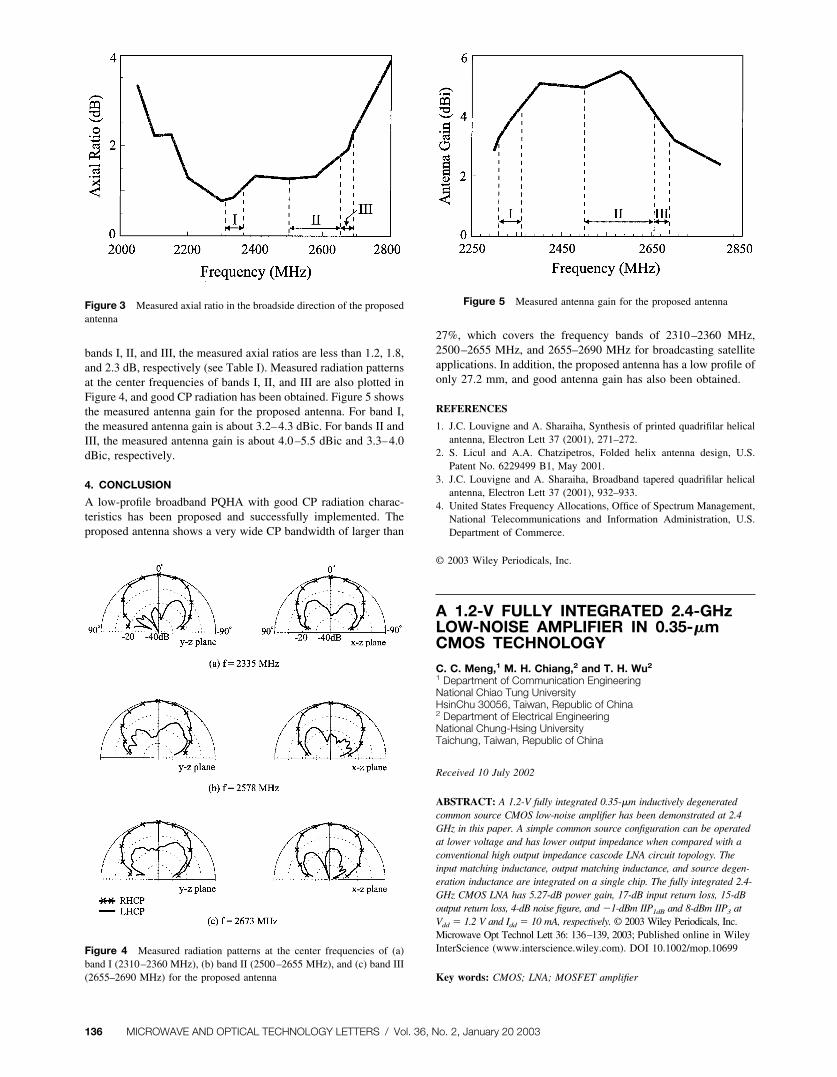
bands I, II, and III, the measured axial ratios are less than 1.2, 1.8,and 2.3 dB, respectively (see Table I). Measured radiation patternsat the center frequencies of bands I, II, and III are also plotted inFigure 4, and good CP radiation has been obtained. Figure 5 showsthe measured antenna gain for the proposed antenna. For band I,the measured antenna gain is about 3.2–4.3 dBic. For bands II andIII, the measured antenna gain is about 4.0–5.5 dBic and 3.3–4.0dBic, respectively.
4. CONCLUSION
A low-profile broadband PQHA with good CP radiation charac-teristics has been proposed and successfully implemented. Theproposed antenna shows a very wide CP bandwidth of larger than
27%, which covers the frequency bands of 2310–2360 MHz,2500–2655 MHz, and 2655–2690 MHz for broadcasting satelliteapplications. In addition, the proposed antenna has a low profile ofonly 27.2 mm, and good antenna gain has also been obtained.
REFERENCES
1. J.C. Louvigne and A. Sharaiha, Synthesis of printed quadrifilar helicalantenna, Electron Lett 37 (2001), 271–272.
2. S. Licul and A.A. Chatzipetros, Folded helix antenna design, U.S.Patent No. 6229499 B1, May 2001.
3. J.C. Louvigne and A. Sharaiha, Broadband tapered quadrifilar helicalantenna, Electron Lett 37 (2001), 932–933.
4. United States Frequency Allocations, Office of Spectrum Management,National Telecommunications and Information Administration, U.S.Department of Commerce.
© 2003 Wiley Periodicals, Inc.
A 1.2-V FULLY INTEGRATED 2.4-GHzLOW-NOISE AMPLIFIER IN 0.35-�mCMOS TECHNOLOGY
C. C. Meng,1 M. H. Chiang,2 and T. H. Wu2
1 Department of Communication EngineeringNational Chiao Tung UniversityHsinChu 30056, Taiwan, Republic of China2 Department of Electrical EngineeringNational Chung-Hsing UniversityTaichung, Taiwan, Republic of China
Received 10 July 2002
ABSTRACT: A 1.2-V fully integrated 0.35-�m inductively degeneratedcommon source CMOS low-noise amplifier has been demonstrated at 2.4GHz in this paper. A simple common source configuration can be operatedat lower voltage and has lower output impedance when compared with aconventional high output impedance cascode LNA circuit topology. Theinput matching inductance, output matching inductance, and source degen-eration inductance are integrated on a single chip. The fully integrated 2.4-GHz CMOS LNA has 5.27-dB power gain, 17-dB input return loss, 15-dBoutput return loss, 4-dB noise figure, and �1-dBm IIP1dB and 8-dBm IIP3 atVdd � 1.2 V and Idd � 10 mA, respectively. © 2003 Wiley Periodicals, Inc.Microwave Opt Technol Lett 36: 136–139, 2003; Published online in WileyInterScience (www.interscience.wiley.com). DOI 10.1002/mop.10699
Key words: CMOS; LNA; MOSFET amplifier
Figure 3 Measured axial ratio in the broadside direction of the proposedantenna
Figure 4 Measured radiation patterns at the center frequencies of (a)band I (2310–2360 MHz), (b) band II (2500–2655 MHz), and (c) band III(2655–2690 MHz) for the proposed antenna
Figure 5 Measured antenna gain for the proposed antenna
136 MICROWAVE AND OPTICAL TECHNOLOGY LETTERS / Vol. 36, No. 2, January 20 2003