LOW FRICTION COATINGS – A NEW DESIGN … FRICTION COATINGS – A NEW DESIGN ELEMENT FOR ENGINEERS...
4
LOW FRICTION COATINGS – A NEW DESIGN ELEMENT FOR ENGINEERS B. BLUG, G. KONRATH, T. HOLLSTEIN Fraunhofer Institut für Werkstoffmechanik IWM, Wöhlerstr. 11, 79108 Freiburg, GERMANY; e-mail: [email protected] J. BRAND, C. BECKMANN Fraunhofer Institut für Schicht- und Oberflächentechnik IST, Bienroder Weg 54 E, 38108 Braunschweig, GERMANY; e-mail: [email protected] SUMMARY Diamond-like carbon coatings (DLC) combine high wear resistance with low friction coefficients. Both properties enable the protective layers to sustain wide ranges of loading and environmental conditions. At present, low friction coatings are commonly used on an empirical basis but not as a design element. The reason for the empirical approach is the lack of tools for a description of the interaction between the coatings and the substrate. Furthermore it is difficult to obtain information on the fracture properties of the coating – substrate – system (e.g. fracture toughness, adhesion, residual stresses). A spherical indentation provides a simple technique to measure quantitatively the fracture toughness and the adhesion of brittle coatings on a ductile substrate with standard laboratory equipment. DLC coatings on a 100 Cr 6 steel substrate are indented by silicon nitride balls with different diameters and different loads. Fracture patterns (circular and radial cracks, delamination) are analyzed by finite element calculation and the fracture toughness in combination with the interface toughness are estimated. Keywords: DLC Coatings, tribological coatings, low friction coatings, hard coatings, fracture toughness 1 INTRODUCTION Low friction coatings are used today in nearly all fields where a low coefficient of friction and a high wear resistance is required. The applications range from injections nozzles in diesel engines to different kinds of journal and ball bearings. The usual approach is to design the component without taking into account the properties of the coating and then test the component in the application. The reason for this trial and error approach is the difficulty to determine properties of hard coatings other than the hardness, Youngs modulus and the residual stresses. But in most tribological application the adherence of the coating to the substrate and the fracture toughness are the lifetime determining properties of a coating substrate system. Common methods to determine the adhesion of a coating substrate system are the blister test, the scratch test, drill test and the cut test [1]. These methods have all shortcomings in the case of very hard brittle coatings. For example the erosion of the probe hampers the measuring of the adherence in the scratch test [1]. Besides the methods mentioned above there are several methods using different types of indenters ranging from spherical indenters to pyramids [1]. The indenters used in this work are macroscopical spherical indenters made of Silicon Nitride (Si 3 N 4 ) with diameters between 2.38 and 10 mm. With the 2.38 mm Si 3 N 4 ball it is possible to test the adherence as well as the fracture toughness of the DLC coating with one single indenter. 2 COATING The combination of the mechanical properties along with the properties of a low friction coating led to a wide distribution of diamond like carbon coatings (DLC) in tribological applications. Depending on the coating process (PVD, CVD, Laser arc), the fabrication parameters and different do pants the hardness may be adjusted between 700 HV and 4000 HV and the young’s modulus between 70 and 400 GPa. Along with low wear rates and a coefficient of friction adjustable between 0.01 and 0.2 (depending on the tribological partners, [2]) these features enable engineers to adapt the DLC coating to the required properties in application. The analysed DLC films were prepared by using a RF-PECVD process. The RF glow discharge leads to reactive gas species and ions in a atmosphere of a hydrocarbon/argon gas mixture. These high energy particles are necessary to build a hard carbon coating. With a typical growth rate of 2-3 microns per hour the deposition temperature is below 200 °C. The coatings were deposited with constant process parameters. To facilitate the comparison of experimental and numerical results a gradient within the coating and a metallic adherent layer in the coatings interface were omitted. The use of gradients and metallic adherent layers would of course increase the performance of DLC coatings by factors. The coating had following properties: Youngs modulus E = 255 GPa (measured by nanoindentation), Poisson ratio ν = 0.3 (estimated by literature [3]), residual stresses σ 0 = 1.8 GPa (measured by substrate bending), thickness t = 2 μm and a coefficient of friction μ = 0.2 (against Si 3 N 4 ).
Transcript of LOW FRICTION COATINGS – A NEW DESIGN … FRICTION COATINGS – A NEW DESIGN ELEMENT FOR ENGINEERS...
LOW FRICTION COATINGS – A NEW DESIGN ELEMENT FOR ENGINEERS B. BLUG, G. KONRATH, T. HOLLSTEIN Fraunhofer Institut für Werkstoffmechanik IWM, Wöhlerstr. 11, 79108 Freiburg, GERMANY; e-mail: [email protected] J. BRAND, C. BECKMANN Fraunhofer Institut für Schicht- und Oberflächentechnik IST, Bienroder Weg 54 E, 38108 Braunschweig, GERMANY; e-mail: [email protected] SUMMARY Diamond-like carbon coatings (DLC) combine high wear resistance with low friction coefficients. Both properties enable the protective layers to sustain wide ranges of loading and environmental conditions. At present, low friction coatings are commonly used on an empirical basis but not as a design element. The reason for the empirical approach is the lack of tools for a description of the interaction between the coatings and the substrate. Furthermore it is difficult to obtain information on the fracture properties of the coating – substrate – system (e.g. fracture toughness, adhesion, residual stresses). A spherical indentation provides a simple technique to measure quantitatively the fracture toughness and the adhesion of brittle coatings on a ductile substrate with standard laboratory equipment. DLC coatings on a 100 Cr 6 steel substrate are indented by silicon nitride balls with different diameters and different loads. Fracture patterns (circular and radial cracks, delamination) are analyzed by finite element calculation and the fracture toughness in combination with the interface toughness are estimated.
Keywords: DLC Coatings, tribological coatings, low friction coatings, hard coatings, fracture toughness
1 INTRODUCTION Low friction coatings are used today in nearly all fields where a low coefficient of friction and a high wear resistance is required. The applications range from injections nozzles in diesel engines to different kinds of journal and ball bearings. The usual approach is to design the component without taking into account the properties of the coating and then test the component in the application. The reason for this trial and error approach is the difficulty to determine properties of hard coatings other than the hardness, Youngs modulus and the residual stresses. But in most tribological application the adherence of the coating to the substrate and the fracture toughness are the lifetime determining properties of a coating substrate system.
Common methods to determine the adhesion of a coating substrate system are the blister test, the scratch test, drill test and the cut test [1]. These methods have all shortcomings in the case of very hard brittle coatings. For example the erosion of the probe hampers the measuring of the adherence in the scratch test [1].
Besides the methods mentioned above there are several methods using different types of indenters ranging from spherical indenters to pyramids [1]. The indenters used in this work are macroscopical spherical indenters made of Silicon Nitride (Si3N4) with diameters between 2.38 and 10 mm. With the 2.38 mm Si3N4 ball it is possible to test the adherence as well as the fracture toughness of the DLC coating with one single indenter.
2 COATING The combination of the mechanical properties along with the properties of a low friction coating led to a wide distribution of diamond like carbon coatings (DLC) in tribological applications. Depending on the coating process (PVD, CVD, Laser arc), the fabrication parameters and different do pants the hardness may be adjusted between 700 HV and 4000 HV and the young’s modulus between 70 and 400 GPa. Along with low wear rates and a coefficient of friction adjustable between 0.01 and 0.2 (depending on the tribological partners, [2]) these features enable engineers to adapt the DLC coating to the required properties in application.
The analysed DLC films were prepared by using a RF-PECVD process. The RF glow discharge leads to reactive gas species and ions in a atmosphere of a hydrocarbon/argon gas mixture. These high energy particles are necessary to build a hard carbon coating. With a typical growth rate of 2-3 microns per hour the deposition temperature is below 200 °C. The coatings were deposited with constant process parameters.
To facilitate the comparison of experimental and numerical results a gradient within the coating and a metallic adherent layer in the coatings interface were omitted. The use of gradients and metallic adherent layers would of course increase the performance of DLC coatings by factors.
The coating had following properties: Youngs modulus E = 255 GPa (measured by nanoindentation), Poisson ratio ν = 0.3 (estimated by literature [3]), residual stresses σ0 = 1.8 GPa (measured by substrate bending), thickness t = 2 µm and a coefficient of friction µ = 0.2 (against Si3N4).
3 EXPERIMENTALS The spherical indentation tests were conducted with a CK10 testing machine of Engineering Systems (Nottingham, UK). Silicon nitride balls of different diameters were pressed into the coating substrate system (DLC, 100 Cr 6 steel) at multiple loads. The resulting fracture patterns were observed with an optical microscope.
At loads lower than the plastic limit of the substrate only elastic deformation takes place, no lasting deformation of the coating substrate system is observed. At higher loads the substrate deforms plastically, but the coating itself will deform elastically because of the high yield limit.
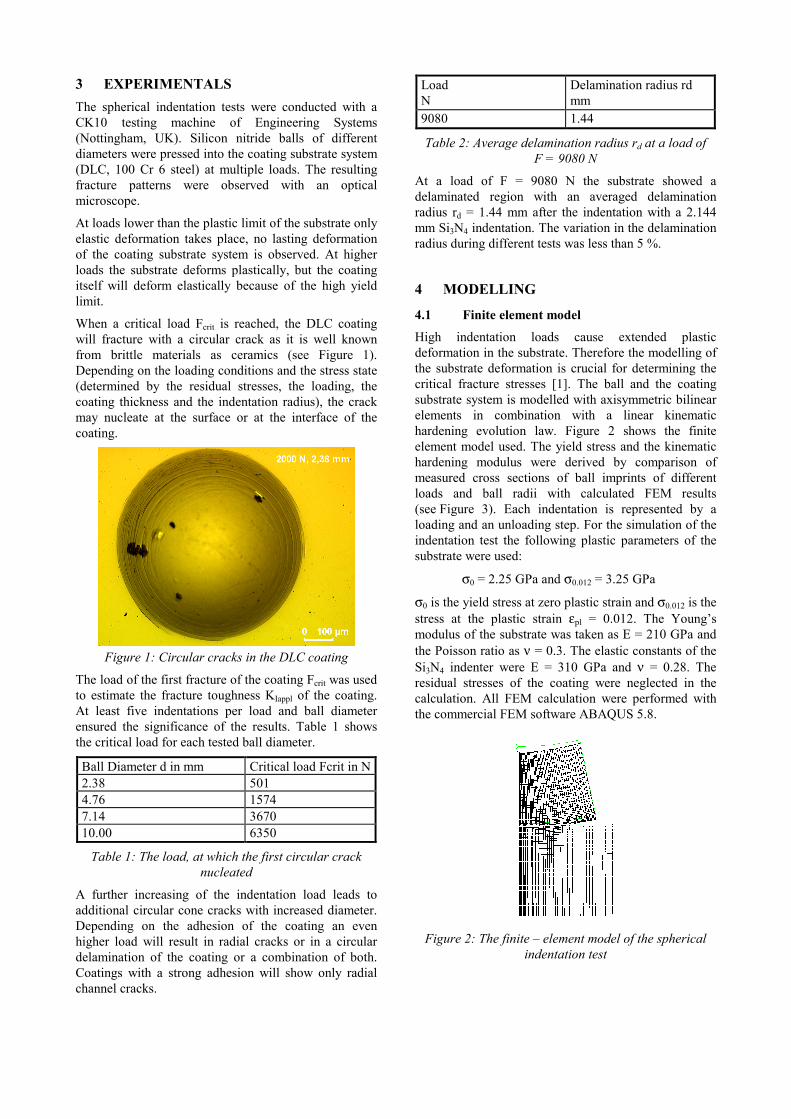
When a critical load Fcrit is reached, the DLC coating will fracture with a circular crack as it is well known from brittle materials as ceramics (see Figure 1). Depending on the loading conditions and the stress state (determined by the residual stresses, the loading, the coating thickness and the indentation radius), the crack may nucleate at the surface or at the interface of the coating.
Figure 1: Circular cracks in the DLC coating
The load of the first fracture of the coating Fcrit was used to estimate the fracture toughness KIappl of the coating. At least five indentations per load and ball diameter ensured the significance of the results. Table 1 shows the critical load for each tested ball diameter.
Ball Diameter d in mm Critical load Fcrit in N 2.38 501 4.76 1574 7.14 3670 10.00 6350
Table 1: The load, at which the first circular crack nucleated
A further increasing of the indentation load leads to additional circular cone cracks with increased diameter. Depending on the adhesion of the coating an even higher load will result in radial cracks or in a circular delamination of the coating or a combination of both. Coatings with a strong adhesion will show only radial channel cracks.
Load N
Delamination radius rd mm
9080 1.44
Table 2: Average delamination radius rd at a load of F = 9080 N
At a load of F = 9080 N the substrate showed a delaminated region with an averaged delamination radius rd = 1.44 mm after the indentation with a 2.144 mm Si3N4 indentation. The variation in the delamination radius during different tests was less than 5 %.
4 MODELLING
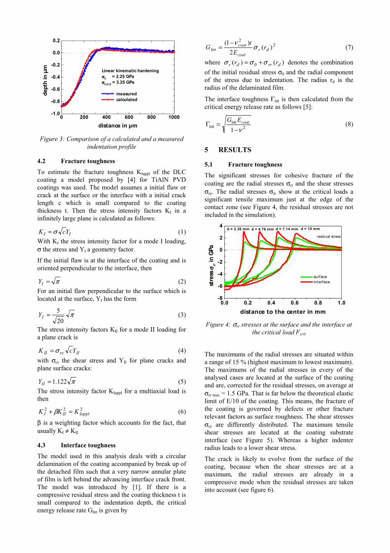
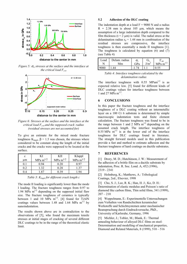
4.1 Finite element model High indentation loads cause extended plastic deformation in the substrate. Therefore the modelling of the substrate deformation is crucial for determining the critical fracture stresses [1]. The ball and the coating substrate system is modelled with axisymmetric bilinear elements in combination with a linear kinematic hardening evolution law. Figure 2 shows the finite element model used. The yield stress and the kinematic hardening modulus were derived by comparison of measured cross sections of ball imprints of different loads and ball radii with calculated FEM results (see Figure 3). Each indentation is represented by a loading and an unloading step. For the simulation of the indentation test the following plastic parameters of the substrate were used:
σ0 = 2.25 GPa and σ0.012 = 3.25 GPa
σ0 is the yield stress at zero plastic strain and σ0.012 is the stress at the plastic strain εpl = 0.012. The Young’s modulus of the substrate was taken as E = 210 GPa and the Poisson ratio as ν = 0.3. The elastic constants of the Si3N4 indenter were E = 310 GPa and ν = 0.28. The residual stresses of the coating were neglected in the calculation. All FEM calculation were performed with the commercial FEM software ABAQUS 5.8.
Figure 2: The finite – element model of the spherical
indentation test
0 200 400 600 800 1000-1.0
-0.8
-0.6
-0.4
-0.2
0.0
0.2
Linear kinematic hardeningσσσσ0 = 2.25 GPaσσσσ0.012 = 3.25 GPa
measured calculated
dept
h in
µm
distance in µm
Figure 3: Comparison of a calculated and a measured indentation profile
4.2 Fracture toughness To estimate the fracture toughness KIappl of the DLC coating a model proposed by [4] for TiAlN PVD coatings was used. The model assumes a initial flaw or crack at the surface or the interface with a initial crack length c which is small compared to the coating thickness t. Then the stress intensity factors KI in a infinitely large plane is calculated as follows:
II YcK σ= (1) With KI the stress intensity factor for a mode I loading, σ the stress and YI a geometry factor.
If the initial flaw is at the interface of the coating and is oriented perpendicular to the interface, then
π=IY (2) For an initial flaw perpendicular to the surface which is located at the surface, YI has the form
π205=IY (3)
The stress intensity factors KII for a mode II loading for a plane crack is
IIrzII YcK σ= (4) with σrz the shear stress and YII for plane cracks and plane surface cracks:
π122.1=IIY (5) The stress intensity factor KIappl for a multiaxial load is then
222IapplIII KKK =+ β (6)
β is a weighting factor which accounts for the fact, that usually KI ≠ KII.
4.3 Interface toughness The model used in this analysis deals with a circular delamination of the coating accompanied by break up of the detached film such that a very narrow annular plate of film is left behind the advancing interface crack front. The model was introduced by [1]. If there is a compressive residual stress and the coating thickness t is small compared to the indentation depth, the critical energy release rate GInt is given by
22
)(2
)1(dr
coat
coatInt r
Et
G σν−
= (7)
where )()( 0 drrdr rr σσσ += denotes the combination of the initial residual stress σ0 and the radial component of the stress due to indentation. The radius rd is the radius of the delaminated film.
The interface toughness Γint is then calculated from the critical energy release rate as follows [5]:
2int
int 1 ν−=Γ coatEG
(8)
5 RESULTS
5.1 Fracture toughness The significant stresses for cohesive fracture of the coating are the radial stresses σrr and the shear stresses σrz. The radial stresses σrr show at the critical loads a significant tensile maximum just at the edge of the contact zone (see Figure 4, the residual stresses are not included in the simulation).
0.0 0.2 0.4 0.6 0.8 1.0-8
-6
-4
-2
0
2
4
residual stress
d = 10 mmd = 7.14 mmd = 4.76 mmd = 2.38 mm
surface interfacest
ress
σσ σσrr in
GPa
distance to the center in mm
Figure 4: σrr stresses at the surface and the interface at the critical load Fcrit
The maximums of the radial stresses are situated within a range of 15 % (highest maximum to lowest maximum). The maximums of the radial stresses in every of the analysed cases are located at the surface of the coating and are, corrected for the residual stresses, on average at σrr max = 1.5 GPa. That is far below the theoretical elastic limit of E/10 of the coating. This means, the fracture of the coating is governed by defects or other fracture relevant factors as surface roughness. The shear stresses σrz are differently distributed. The maximum tensile shear stresses are located at the coating substrate interface (see Figure 5). Whereas a higher indenter radius leads to a lower shear stress.
The crack is likely to evolve from the surface of the coating, because when the shear stresses are at a maximum, the radial stresses are already in a compressive mode when the residual stresses are taken into account (see figure 6).
0.0 0.2 0.4 0.6 0.8 1.0-0.20.00.20.40.60.81.01.21.4
805 MPa
1,05 GPa
1.2 GPa
753 MPa
Interface Surface
stre
ss σσ σσ
rz in
GPa
distance to the center in mm
Figure 5: σrz stresses at the surface and the interface at the critical load Fcrit
0.10 0.15 0.20 0.25 0.30-6
-4
-2
0
2
4d = 2.38 mm
σσσσrr
σσσσrz
σσσσrz
σσσσrr
supposed crack radius
Surface Interface
stre
ss in
GPa
distance to the center in mm
Figure 6: Stresses at the surface and the interface at the critical load Fcrit and the supposed crack radius
(residual stresses are not accounted for) To give an estimate for the mixed mode fracture toughness KIappl, β = 1.5 was chosen, the stresses where considered to be constant along the length of the initial cracks and the cracks were supposed to be located at the surface.
c µm
KI MPa m1/2
KII MPa m1/2
KIappl MPa m1/2
0.1 0.94 0.20 0.97 0.2 1.32 0.28 1.37 0.4 1.87 0.39 1.94
Table 3: KIappl for different crack length c The mode II loading is significantly lower than the mode I loading. The fracture toughness ranges from 0.97 to 1.94 MPa m1/2 depending on the supposed initial flaw size. The fracture toughness of ceramics is typically between 1 and 10 MPa m1/2. [4] found for TiAlN coatings values between 1.48 and 1.64 MPa m1/2 by nanoindentation.
The results shown above are in contradiction to the observations of [5], who found the maximum tensile stresses at initial stages of cracking of several different DLC coatings to be in the range of the theoretical elastic limit.
5.2 Adhesion of the DLC coating The indentation depth at a load F = 9080 N and a radius R = 2.38 mm is about 105 µm, which means the assumption of a large indentation depth compared to the film thickness (t = 2 µm) is valid. The radial stress at the delamination radius rd = 1.44 mm in combination of the residual stresses are compressive, the interface toughness is then essentially a mode II toughness [1]. The toughness is calculated by equation (6) and (7) (see Table 4)
Load N
Delam. radius Mm
σr GPa
Gc J/m2
Γint MPa m1/2
9080 1.44 -1.74 1.1 0.55
Table 4: Interface toughness calculated by the delamination radius
The interface toughness with 0.55 MPam1/2 is as expected relative low. [5] found for different kinds of DLC coatings values for interface toughness between 1 and 27 MPa m1/2
. 6 CONCLUSIONS In this paper the fracture toughness and the interface toughness of a DLC coating without an intermetallic layer on a 100 Cr 6 substrate is determined by simple macroscopic indentation tests and finite element calculation. The fracture toughness was found to be in the range between 1 and 2 MPa m1/2 depending on the assumed crack length. The interface toughness of 0.55 MPa m1/2 is at the lower end of the interface toughness for DLC coatings found in literature. The straight forward models used in this publication provide a fast and method to estimate adhesion and the fracture toughness of hard coatings on ductile substrates. 7 REFERENCES [1] Drory, M. D.; Hutchinson, J. W.: Measurement of the adhesion of a brittle film on a ductile substrate by indentation, Proc. R. Soc. Lond. A, 452 (1996), 2319 - 2341 [2] Holmberg, K.; Matthews, A.: Tribological Coatings, 2ed., Elsevier, 1998 [3] Cho, S. J.; Lee, R. K.; Han, H. J.; Ko, D. H.: Determination of elastic modulus and Poisson´s ratio of diamond like carbon films, Thin solid films, 341 (1999), 207 – 210 [4] Weppelmann, E.: Experimentelle Untersuchungen zum Verhalten von Randschichten keramischer Werkstoffe und Schichtsystemen unter mechanischer Beanspruchung durch Eindruckversuche, PhD., University of Karlsruhe, Germany, 1996 [5] Michler, J.; Tobler, M.; Blank, E.: Thermal annealing behaviour of alloyed DLC films on steel: Determination and modelling of mechanical properties, Diamond and Related Materials, 8 (1999), 510 – 516