Low Frequency Waves in HF Heating of Mid-latitude Ionosphere
21
Low Frequency Waves in HF Heating of Mid-latitude Ionosphere Surja Sharma, Bengt Eliasson*, Xi Shao, Gennady Milikh and Dennis Papadopoulos University of Maryland, College Park *University of Strathclyde, Glasgow, UK IES 2015 Alexandria, VA Supported by NSF Grant AGS-1158206
Transcript of Low Frequency Waves in HF Heating of Mid-latitude Ionosphere

Low Frequency Waves in HF Heating of Mid-latitude Ionosphere
Surja Sharma, Bengt Eliasson*, Xi Shao, Gennady Milikh and Dennis Papadopoulos
University of Maryland, College Park
*University of Strathclyde, Glasgow, UK
IES 2015
Alexandria, VA
Supported by NSF Grant AGS-1158206
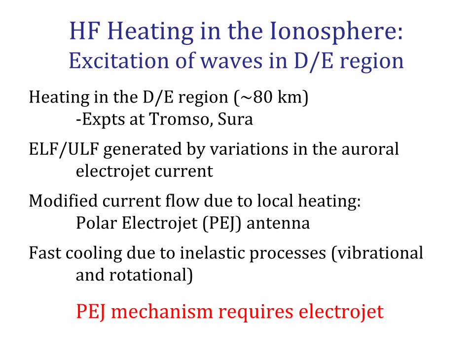
HF Heating in the Ionosphere: Excitation of waves in D/E region
Heating in the D/E region (~80 km) -Expts at Tromso, Sura ELF/ULF generated by variations in the auroral electrojet current Modified current flow due to local heating: Polar Electrojet (PEJ) antenna Fast cooling due to inelastic processes (vibrational and rotational)
PEJ mechanism requires electrojet

HF Heating in the Ionosphere: Excitation of waves in F region
Heating in the F region (~300 km) -Expts at HAARP Magnetosonic (MS) waves excited by diamagnetic current due to heating Shear Alfven (SA) waves generated by MS waves in the Hall layer Propagation of Alfven waves to the ground and the magnetosphere
ELF waves generation without electrojet

ELF Waves in HF heating: High-latitude Ionosphere
Papadopoulos et al., GRL 2011
Physical mechanism

ELF Waves in HF heating: High-latitude Ionosphere
Eliasson et al., JGR 2012
DEMETER Observations of Shear Alfvén waves (2.5 Hz): HAARP expt

Collisional Hall-MHD model Faraday’s and Ampère’s laws Ion momentum equation Momentum equation for inertial-less electrons
Simulation Model: Collisional Hall-MHD
Electron pressure Pe modulated by RF wave
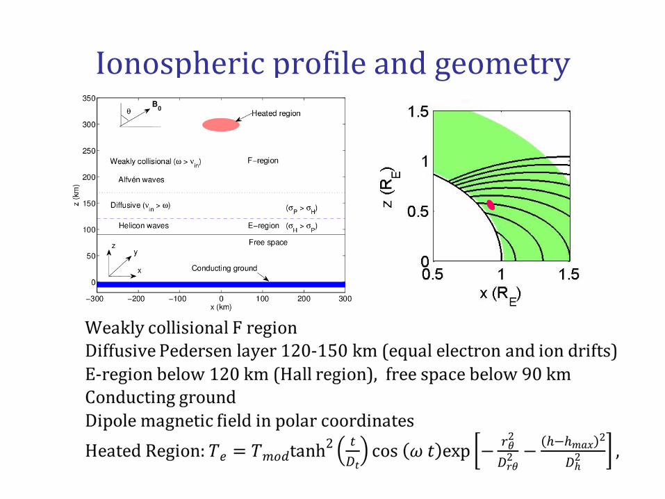
Ionospheric profile and geometry
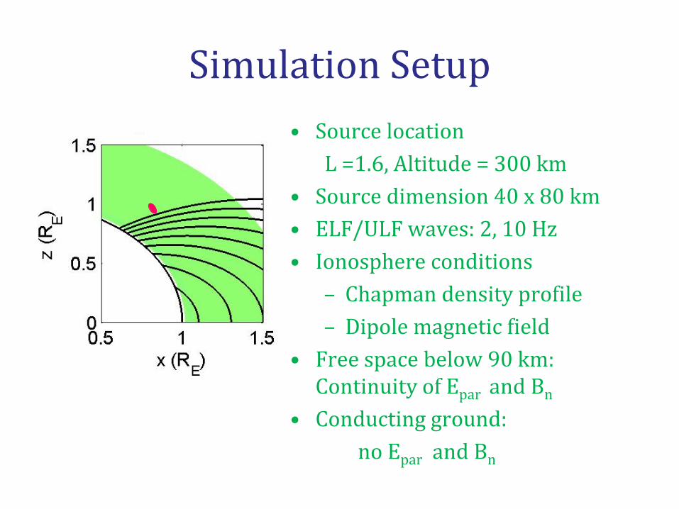
Simulation Setup • Source location L =1.6, Altitude = 300 km • Source dimension 40 x 80 km • ELF/ULF waves: 2, 10 Hz • Ionosphere conditions
– Chapman density profile – Dipole magnetic field
• Free space below 90 km: Continuity of Epar and Bn
• Conducting ground: no Epar and Bn
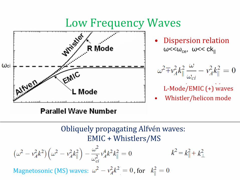
Low Frequency Waves • Dispersion relation
ω<<ωce, ω<< ck||
• R-Mode/whistler (-) and
L-Mode/EMIC (+) waves • Whistler/helicon mode
Obliquely propagating Alfvén waves: EMIC + Whistlers/MS
Magnetosonic (MS) waves: , for

Simulation Results: 2Hz (Movie)

Simulation Results 10Hz (Movie)

Main features • Magnetosonic waves are created by HF heating and
propagate at large angles to magnetic field lines. • Whistlers (R-mode) and EMIC (L-mode) waves
propagate mainly along magnetic field lines • Direct generation of EMIC waves at the source region • Generation of EMIC and whistlers via mode conversion
of MS waves in the E-region. • 10Hz: EMIC wavelength and propagation speed
significantly smaller than for Whistlers.
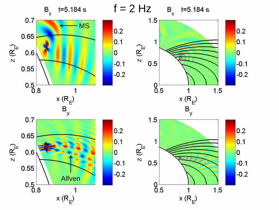
F =2 Hz
Alfven
MS
f = 2 Hz

f = 10 Hz f = 10 Hz
EMIC
Whistler + EMIC
MS
Conversion MS -> Whistler
+EMIC
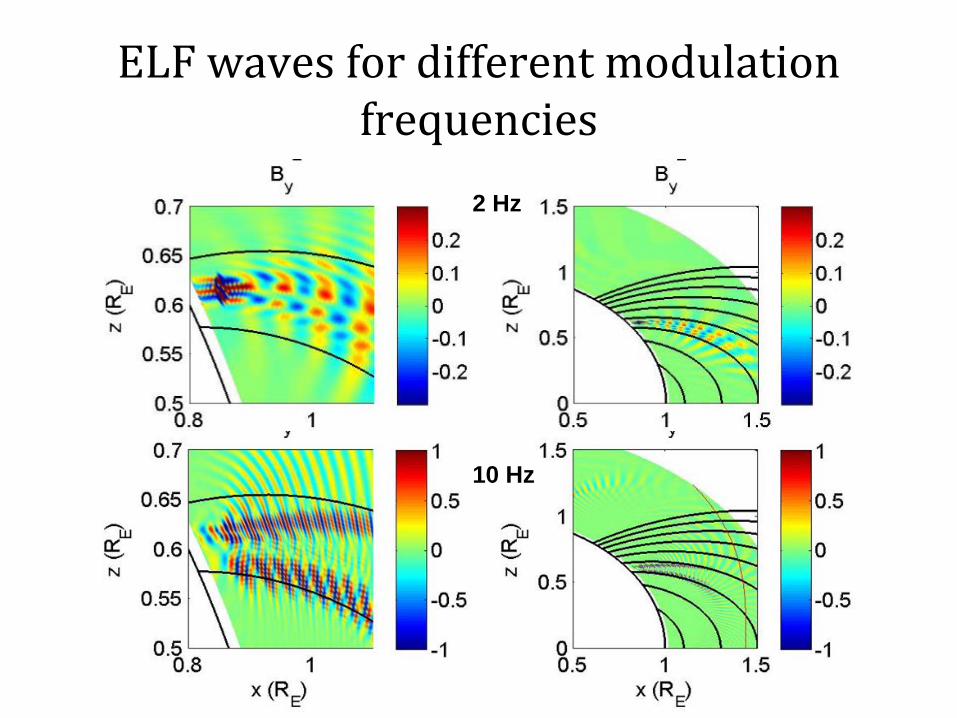
ELF waves for different modulation frequencies
2 Hz
10 Hz

EMIC Waves and Whistlers (10 Hz )

Whistler / EMIC features
• Magnetosonic waves (shown by Bx) are created by HF heating and propagate upwards to the magnetosphere and downwards to E-region, where they convert to whistlers and EMIC waves.
• EMIC waves also generated at the source region • EMIC and Whistler waves (shown by By and Bx) propagate
along magnetic field lines • 10 Hz: EMIC waves cannot propagate beyond ion cyclotron
resonance layer where their wavelength goes to zero • EMIC relatively short wavelength compared to whistlers

Summary
• Generation of ELF waves by HF heating in the F region - in the
absence of an electrojet • Realisitic ionospheric profile, collisionality and dipole
magnetic field geometry • Direct generation of EMIC waves in source region, mode
conversion of MS waves via Hall currents in the E-region • Provides features for comparison with satellite data during
passes over the heating site. • Low frequency waves (plasma eigenmodes) in HF heating
with no modulation
• References: • B. Eliasson, C.-L. Chang, and K. Papadopoulos (2012), Generation
of ELF and ULF electromagnetic waves by modulated heating of the ionospheric F2 region, J. Geophys. Res., 117, doi:10.1029/2012JA017935
• Papadopoulos, K., N. A. Gumerov, X. Shao, I. Doxas, and C. L. Chang
• (2011), HF-driven currents in the polar ionosphere, Geophys. Res. Lett.,
• 38, L12103, doi:10.1029/2011GL047368. • Papadopoulos, K., C.-L. Chang, J. Labenski, and T. Wallace (2011),
First • demonstration of HF-driven ionospheric currents, Geophys. Res.
Lett., 38, • L20107, doi:10.1029/2011GL049263.

f = 5 Hz
Whistler
MS
Alfven

Motivation and observation • Ionospheric ULF Wave Generation without Electrojet
[Papadopoulos et al., 2011a,b; Eliasson, Chang and Papadopoulos, 2012] – Both simulation and experiments – Up to 50 Hz – Ionospheric current drive (ICD) in F layer – Predictable and repeatable signal generation on daily basis – Viable technique in low latitude regions with robust F
• ICD-driven ULF Wave generation and injection in EIW and the radiation belt – A comprehensive simulation model is needed
• Inducing energetic particle precipitation from radiation belt through resonant pitch angle scattering – Pitch angle scattering protons with Alfven waves [Shao et al.,
2009] – EMIC waves interact resonantly with relatvisitc electrons


![Radio studies of the high-latitude ionosphere during the solar ......Eclipses ft nd the Ionosphere" edited by W. J. B. Beynon and G. lVI. Brown [1955]. The only previous thorough investigation](https://static.fdocuments.in/doc/165x107/607d26dec6b63179784bd9ca/radio-studies-of-the-high-latitude-ionosphere-during-the-solar-eclipses.jpg)