Low Frequency Radio Observations From Space: …...Radioastronomy on the Moon is an Old idea. First...
24
Low Frequency Radio Observations From Space: Now and Next B. Cecconi (1) , P. Zarka (1) , M. Klein Wolt (2) , S.L.G. Hess (1) , J. Bergman (3) (1) LESIA, Observatoire de Paris, CNRS, UPMC, Univ. Paris Diderot, Meudon, France (2) Department of Physics, Radboud University Nijmegen, Netherlands. (3) IRFU, Uppsala, Sweden. mercredi 19 février 2014
Transcript of Low Frequency Radio Observations From Space: …...Radioastronomy on the Moon is an Old idea. First...

Low Frequency Radio Observations
From Space: Now and Next
B. Cecconi(1), P. Zarka(1), M. Klein Wolt(2), S.L.G. Hess(1), J. Bergman(3)
(1) LESIA, Observatoire de Paris, CNRS, UPMC, Univ. Paris Diderot, Meudon, France(2) Department of Physics, Radboud University Nijmegen, Netherlands.
(3) IRFU, Uppsala, Sweden.
mercredi 19 février 2014

Outline
•Near Earth low frequency radio environment
•Case for Radio observation from the Moon
•Space radio instrumentation - Goniopolarimetry
•Future projects
NB: Low frequency = a few kHz to 50 MHz
mercredi 19 février 2014

No place on/near Earth is Dark at Low Frequencies (LF radio "smog")
24h averages from Wind/WAVES
40 RE
93 RE
157 RE
mercredi 19 février 2014

Sensitivity Limitation: background temperature is high !
Tsky freq (MHz)
3.3 ! 105 10
2.6 ! 106 5
2.0 ! 107 1
2.6 ! 107 0.5
5.2 ! 106 0.25
galactic synchrotron
emission
free-free absorption
Galactic background flux density detected by a short dipole antenna : Ssky (Wm-2Hz-1) = 2kTsky/Aeff = 2kTskyλ2/Ω with Ω=8π/3, Aeff=3λ2/8π
→ sensitivity with N dipoles, bandwidth b, integration time τ : Smin = Ssky1/C with C = N(bτ)1/2
mercredi 19 février 2014

Except behind the moon:
RAE-2 occultation of Earth (1973) RAE-2 occultation of a solar storm
RAE-2 : 1100 km circular orbit
inclined by 59° / lunar equator
mercredi 19 février 2014

Radioastronomy on the Moon is an Old idea.First proposals pre-date Apollo missions !
• 1964 Gorgolewski identifies the far side of the Moon as a good site for VLF radio interferometry (Lunar International Laboratory Panel)
• 1966 Research Program on Radio Astronomy and Plasma for Apollo Applications Program Lunar Surface Missions (Report from North American Aviation Inc.)
• 1967 Utilization of Crater Reflectors for Lunar Radio Astronomy (J.M. Greiner, WG on Extraterrestrial Resources)
• 1968 RAE-1 VLF Earth satellite (0.2-9.2 MHz)
• 1973 RAE-2 VLF Moon satellite (0.02-13.1 MHz, 1100 km, 59°inclination/lunar equator)
• 1983 VLF radio observatory on the Moon proposed by Douglas & Smith in Lunar Bases and Space Activities of the 21 Century
• 1988 Workshop: Burns et al., A Lunar Far-Side Very Low Frequency array (NASA)
• 1992 Design study: Astronomical Lunar Low Frequency Array (Hughes Aircraft Co.)
• 1993 Design study: Mendell et al., International Lunar Farside Observatory and Science Station (ISU)
• 1997 Design study: Bely et al., Very Low Frequency Array on the Lunar Far Side (ESA)
• 1998 MIDEX proposal: Jones et al., Astronomical Low Frequency Array (ALFA), JPL, NRL, GSFC,…
• 2003 GSFC workshop for the Solar Imaging Radio Array (SIRA)
• 2005-8 Conferences Moon&Beyond, Joint statement to ESA, LIFE & MoonNext projects
• 2009+ ESA Lunar Lander project
• 2010 Farside Explorer (response to M3 call)
The Moon (Far side especially) has been long recognized as unique astronomical platform, and a radio quiet zone by International Telecommunications Union
mercredi 19 février 2014

Lunar ionosphere is very thinlow frequency cut-off near 100 kHz
• Lunar ionosphere is very thin. Dual-frequency Luna spacecraft measurements suggest that an ionised layer, several km thick, builds up on the illuminated side of the Moon, with fpe-max ~0.5 MHz (Vyshlov 1976). No layer seen during the lunar night.
mercredi 19 février 2014

Local radio environment
mercredi 19 février 2014

Very Low Frequency RadioastronomyIdentified Science opportunities
• LF sky mapping + monitoring : radio galaxies, large scale structures (clusters with radio halos, cosmological filaments, …), including polarization, down to a few MHz
• Cosmology : pathfinder measurements of the red-shifted HI line that originates from before the formation of the first stars (dark ages, recombination)
• Interaction of ultra-high energy cosmic rays and neutrinos with the lunar surface
• Low-frequency radio bursts from the Sun, from 1.5 Rs to ~1 AU : Type II & III, CME, ...Space weather - Passive: through scintillation and Faraday rotation - Active: through radar scattering
• Auroral emissions from the giant planets’ magnetospheres in our solar system: rotation periods, modulations by satellites & SW, MS dynamics, seasonal effects, ...First opportunity in decades to study Uranus and Neptune
• Detection of pulsars down to VLF, with implications for interstellar radio propagation : LF cutoff of temporal broadening in 1/f4.4 ? → largest scale of turbulence in ISS ? limit of transient observations ?
• The unknown …
mercredi 19 février 2014

Very Low frequency Radio InterferometryWhat to do better ?
• Solar radio observations (type II, type III)Now: measurements at 1 point (centroid + apparent source size) source spatial extension due to scattering along propagationNext: full imaging => parameters on the source and on scattering
=> or ?
• Planetary radio emissions:Now: only Jupiter is visible from Earth, or you go «on site»Next: Jupiter, Saturne, Uranus, Neptune...
Solar Type III burst
mercredi 19 février 2014

Space Radio AstronomyGoniopolarimetry
• Space based radio antennas: simple dipoles or monopoles with length L of a few meters(impossible to have a reflector large enough to have λ/D << 1)
• Short antenna range (L << λ) : monopole antenna + S/C body ~ effective dipole
• Antenna gain ~ L2sin2θ → null // antenna, max ⊥ to antenna
• Resonance at L ~ λ/2 (multi-lobed, complex gain depending on direction)
236 15. Goniopolarimetry
Antennas
L/!=7/8
L/!=1/8
"L
L/!=9/8
L/!=4/8
L/!=8/8
L/!=2/8
L/!=11/8
L/!=5/8
L/!=16/8
L/!=6/8
Figure 15.2: Beaming pattern of thin boom antennas for various L/! values. The def-inition of angle " is shown on the upper-left panel. The antenna pattern is single lobed(with a null in the antenna direction) for short antennas, i.e. up to L/! ! 1/2. WhenL/! ! 1/10 the antenna pattern does not vary with frequency. With long antennas itbecomes multilobed (L/! > 1/2). Figure adapted from Jasik (1961).
wave is almost constant on the length of the antenna. The voltage measured at theantenna feeds is thus:
V = E(t).he! ! E(t)he! sin !, (15.1)
with ! the angle between the e!ective antenna vector (he!) and the wave vector k.The same formalism holds when the antenna length is longer (L " "/10) but thee!ective antenna vector he! becomes complex and its magnitude depends on thewave vector direction.
A probe antenna is usually a dipole, consisting of two electrical probes (usuallyspherical) attached to the spacecraft by conductive cables with ground shielding.Depending on the antenna design the voltage can be measured at the probe (withpreamplifiers placed right at the probe) or at the end of the cables. The actualbeaming pattern is changed because of these conductive cables. Probe antennasare used on spinning spacecraft. The centrifugal force maintains them in the spinplane. Their length is usually 10 m to 100 m tip-to-tip (100 m for the Clusterspacecraft and the Geotail probe antenna dipole).
A monopole wire antenna consists of a single conductive linear probe whosethickness is usually negligible compared to its length. A perfect dipole antenna is asystem of two identical wire monopole antennas that are aligned and whose feedsare separated by a short distance compared their length. Wire antennas can beeither rigid, self sustained, conductive booms, or centrifugally erected, conductivewires. Boom monopoles are used on 3-axes stabilized spacecraft or as axial an-tennas on spinning spacecraft. Wire monopoles are used for spin-plane antennason spinning spacecraft. Boom monopoles (12 m or less for the Cassini/RPWS,STEREO/Waves, Ulysses and Wind antennas) are significantly shorter than wiremonopoles (! 100 m for Wind and Ulysses), as they are not erected by centrifugalforce.
mercredi 19 février 2014

• Dipole has no angular resolution:∫ antenna pattern = 8π/3 sr
• Solution : Use 2 crossed dipoles connected to a dual-input receiver and correlate measurements on both antenna
• With 3 antennas + crosscorrelations : full wave parameters (flux S, polarization Q,U,V, and wave vector θ, φ)
• Angular resolution depends on phase calibration of receiver + effective antenna calibration (typically ~ 1°, instead of ~90°)
GonioPolarimetry!
!
mercredi 19 février 2014

Goniopolarimetry illustrated(Cassini/RPWS @ Saturn)
Cassini/RPWS dynamic spectrum of Saturn auroral kilometric radiation(classical radio data format)
mercredi 19 février 2014

Goniopolarimetry illustrated(Cassini/RPWS @ Saturn)
Cassini/RPWS dynamic spectrum of Saturn auroral kilometric radiation(classical radio data format)
mercredi 19 février 2014

Goniopolarimetry illustrated(Cassini/RPWS @ Saturn)
Saturn auroral kilometric radio source location from Cassini/RPWS data(left: as seen from Cassini; right: projected on Saturn’s poles along magnetic field lines)
mercredi 19 février 2014

Goniopolarimetric inversions• Point source: Inversions solves for (S, Q, U, V, θ, φ)
Auroral sources (Earth, Jupiter, Saturne)Cassini/RPWS (with 2 or 3 antennas), INTERBAL/Polrad (3 antennas)[Lecacheux, 1978; Ladreiter, 1995; Cecconi, 2010]
• Extended source: Inversions solves for (S, Q, U, V, θ, φ, γ)Solar radio burstsSTEREO/Waves (with 3 antennas), Wind/Waves (spinning antennas)[Manning & Fainberg, 1980; Cecconi et al., 2008; Krupar et al., 2012]
• Linearly-shaped source: Inversions solves for (S, Q, U, V, θ, φ, γ) and brightness profile.[Hess, 2011]
• Full sky source: solves for sky brightness distributionGalactic background mappingCassini/RPWS, STEREO/Waves, Ulysses/URAP[work in progress]
• Compressed sensing: not explored yet at all, but probably worth trying !
mercredi 19 février 2014

Quasi Thermal Noise Spectroscopy
• Plasma resonance with antenna, spectral analysisprovides plasma density, temperature and magneticfield strength
• Requires thin and long antennas (ok for spinning spacecraft, more difficult on stabilized spacecraft)and high spectral resolution radio receiver (Δf/f ~ 1%)
• Absolute determination of plasma parameters: complementary to active measurements (such as Langmuir probes)
mercredi 19 février 2014

Space radio instrument characteristics
• Performances: receiver sensitivity 3-5 nV/Hz1/2, need separate LF & HF due to 1/f spectrum, dynamic range 80-100 dB (without/with Automatic Gain Control (AGC) circuit) → ≤a few MHz : local conditions, Sun & Planets → a few to 100 MHz : all other science measurements
• Resources: ~1 W, a few 100's g, A5 board
• Interfaces: booms, antennas, deployment,EMC (crucial for exploiting the quiet site)
• New R&D action is starting in France between Radioastronomy and Telecom labs for a new generation of digital radio receiver with high dynamic, low power and sampling up to 100 MHz.
BepiColombo/MMO/RPW/Sorbet
Cassini/RPWS antennas (stowed)
A channel of Cassini/RPWS/HFR
mercredi 19 février 2014

Prospective in EuropeProjects of various size
• First: 1-2 sets of electric dipole/monopole antennas, a few meters long (2 landers or lander+rover)
• ESA Lunar Lander, Farside Explorer = Pathfinder technology demonstration for a future radio array on the Moon’s surface.
• ~100 antennas (Aeff = ~3×10⁴ m2 @ 10 MHz, λ~30 m)
• Near or Far side (OLFAR)
• ~1000-10000 antennas = LOFAR-on-the-Moon
• Far side Lunar Radio Array
• Cubesats Projects:
• CIRCUS: - 1 cubesat- ionosphere of Earth
• FOAM: - 2-4 cubesats- auroral radio emissions of Earth
• OLFAR: - 50 cubesats- very low frequency radio astronomy interferometer
mercredi 19 février 2014

CIRCUS Teams involved: UPMC+ESEP+LESIA+TelecomParis
• CIRCUS: Characterization of the Ionosphere using a Radio receiver on a CUbe Sat
• Science objectives: - Quasi thermal noise spectroscopy in the ionosphere of Earth- High temporal cadence: turbulence and microscopic strucuture
• Technology objectives:- Higher TRL for new digital radio receiver under study (LESIA-TelecomParisTech) - Sampling: temporal = 10 ms; spectral = up to 100 Hz (over 50kHz-50MHz)
• Selected technical solution :- 1 cubesat (< 3U), no attitude control- short (10-20 cm) and thin (~1mm) antennas
• Schedule: in 4-5 years ?Orbitography: Low Earth Orbit: ~100 km
mercredi 19 février 2014

FOAMTeams involved: IRFU (SE) + LESIA (FR) + many
• FOAM: FOrmation-flying Auroral Mission
• Science Objectives: - Imaging/mapping of AKR (Auroral Kilometric Radiation of Earth)- Do better than the Cluster mission for AKR (up to 1 MHz)- Measurements inside the radio sources and remote observations- Flux and polarization measurements
• Technology objectives:- Testing passive formation flying (swarm configuration)
• Selected technical solution: - 2 to 4 CubeSat-6U, swarm configuration - Electric tripoles, short antennas (AKR is very intense)
• Schedule: TBD.Orbitography: polar orbit, altitude up to ~5000 km required in auroral zone.
mercredi 19 février 2014

OLFARTeams involved: NL + many other interested
• OLFAR: Orbiting low Frequency Antennas for Radio Astronomy
• Science objectives:- «Dark Ages» (cosmology < 10MHz, redshift ~100, EoR [Epoch of Recombination])- Sun-Earth (space weather), Planets (outer planets: Uranus...)- In situ measurements (Thermal Noise).
• Technology objectives:- Passive formation flying (swarm configuration); inter-satellite distance < 100 km- Inter-satellite communication with GSM, shared computing power, non-space qualified industry components- Radio antennas: 3 electric dipoles axes (6 x 5 m); frequency range: 30 kHz-30 MHz
• Schedule: 2020 ?Orbitography: lunar orbit (or L4-L5 Earth Lagrange Points)
mercredi 19 février 2014
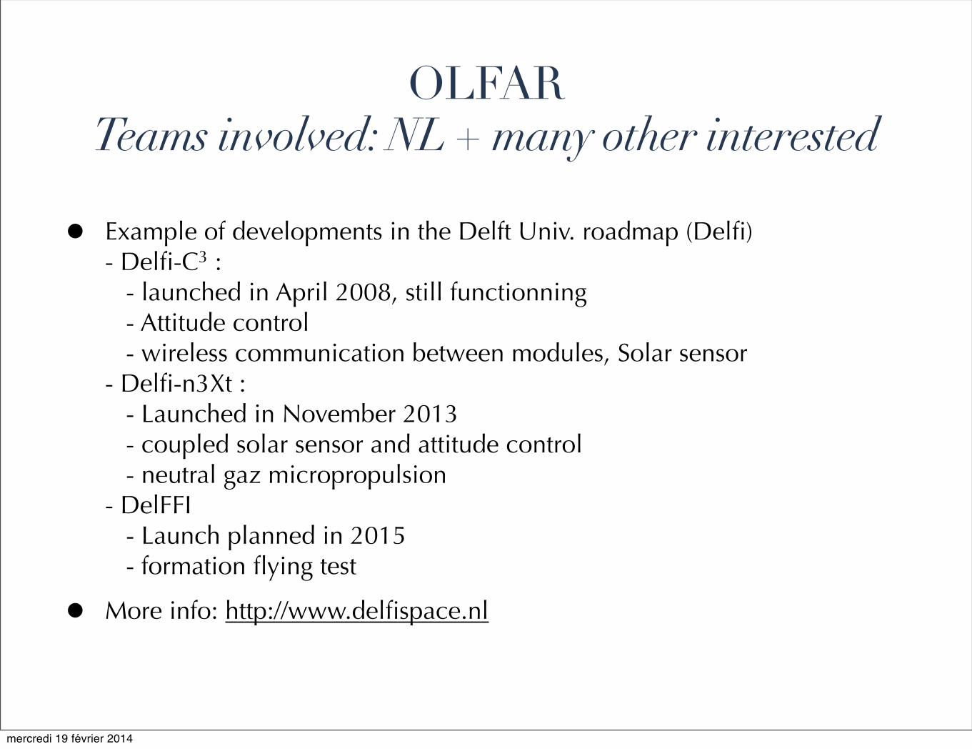
• Example of developments in the Delft Univ. roadmap (Delfi)- Delfi-C3 : - launched in April 2008, still functionning - Attitude control - wireless communication between modules, Solar sensor - Delfi-n3Xt : - Launched in November 2013 - coupled solar sensor and attitude control - neutral gaz micropropulsion- DelFFI - Launch planned in 2015 - formation flying test
• More info: http://www.delfispace.nl
OLFARTeams involved: NL + many other interested
mercredi 19 février 2014

✦ Space instrumentation is required below 10 MHz
✦ Huge interest for all astronomy communities(from cosmology to planetary sciences)
✦ Large scale interferometer is the goal
✦ Pathfinder experiments: Lunar surface (far side) or lunar orbit
✦ Many projects on the roadmap(Farside Explorer, DARE, DEx, FOAM, OLFAR...)
✦ If you are interested participate to NLAP.Netherlands Low-frequency radio Astronomy Platform http://www.astron.nl/nlap/index.php
Conclusions
mercredi 19 février 2014