Low frequency jitter tolerance -...
19
Low frequency jitter tolerance Comments 109, 133, 140 Piers Dawe IPtronics . Charles Moore Avago Technologies
Transcript of Low frequency jitter tolerance -...

Low frequency jitter tolerance
Comments 109, 133, 140
Piers Dawe IPtronics .
Charles Moore Avago Technologies

Supporters
Adee Ran Intel
Mike Dudek QLogic
Mike Li Altera
P802.3bj Jan 2012 Low frequency jitter tolerance 2
Introduction
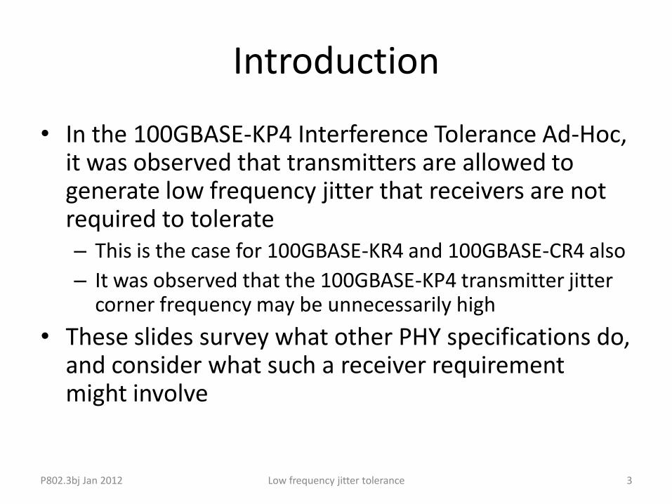
• In the 100GBASE-KP4 Interference Tolerance Ad-Hoc, it was observed that transmitters are allowed to generate low frequency jitter that receivers are not required to tolerate – This is the case for 100GBASE-KR4 and 100GBASE-CR4 also
– It was observed that the 100GBASE-KP4 transmitter jitter corner frequency may be unnecessarily high
• These slides survey what other PHY specifications do, and consider what such a receiver requirement might involve
3 P802.3bj Jan 2012 Low frequency jitter tolerance

Comments 133 and 140 Tx, Rx LF jitter
• Cl 94 SC 3.12.8 P 274 L 32 # 133 TR – Due to complexity of KP4 reciver allowing tracking up to Fbaud/2500 over
burden the reciver when low cost oscilaltor exist to tigthen the TX loop BW
– SuggestedRemedy
– Propose to use Fbaud/10000 or 1.36 MHz for the KP4 CDR loop BW
– Ghiasi, Ali Broadcom [Presently it's 5 MHz or fBaud/2719 - PD]
• Cl 94 SC 3.13.1 P 276 L 54 # 140 TR – Add standalone reciver tracking and inteference test with sinousiodal jitter
– SuggestedRemedy
– The unstress jitter tolernace test is as the following:
– Test patern is PRBS31 each lane must operate with BER 1E-8 or better.
– The applied stress is sinousiodal stress of
– 25 KHz with p-p jitter of 5 UI
– 125 Khz with p-p jitter of 1 UI
– See ghiasi_01_0113
– Ghiasi, Ali Broadcom P802.3bj Jan 2012 Low frequency jitter tolerance 4

Comment 109 Rx LF jitter
• Cl 94 SC 94.3.13.3 P 276 L 40 # 109 TR – Transmitter jitter is measured after a high-pass jitter filter. The receiver must
be able to tolerate low frequency jitter, and the spec must require it. This could be enforced by including low frequency jitter in the receiver interference tolerance specification or by a separate jitter tolerance specification. The latter seems easier. A 2-point spec as used in e.g. 40GBASE-SR4 could be used (just two jitter frequencies rather than a mask).
– SuggestedRemedy
– Add a low frequency jitter tolerance specification to each of clauses 92, 93, 94, as a separate item (not part of receiver interference tolerance, but possibly using the same high loss channel). Make consistent with the transmitter jitter specs, in particular the 3 dB frequency of the jitter measurement filter used for transmitter output jitter measurement.
– Dawe, Piers IPtronics
P802.3bj Jan 2012 Low frequency jitter tolerance 5

Specified or not - background • Many PHY types, also XAUI, XLAUI/CAUI and nPPI, have low frequency
jitter tolerance included in the stressed sensitivity test * (= interference tolerance test *) – See next slide
• Some PHYs have a separate low frequency jitter tolerance spec – See next slide
• One PHY (40GBASE-FR) uses a SONET style jitter tolerance spec – Advantage: compatibility with OTN for dual-use hardware
• Two PHYs (1000BASE-T, 10GBASE-T) require the receiver to work with a compliant transmitter and link segment, specify transmitter jitter – Advantage of implied Rx spec: thoroughness and consistency
– Disadvantage: difficulty in making the worst case channels, open to oversights and disputes
• Some PHYs filter the low frequency Tx jitter in Tx spec but don't require its tolerance in Rx spec – See next slide
• Backup gives more detail for the various PHY types * Testing is one way of verification, but 802.3 is not a test spec, so other methods could be used. We mean that IF the test
were carried out, THEN the item would have to pass.
6 P802.3bj Jan 2012 Low frequency jitter tolerance

Separated or combined? • The majority (17/27) of PHY types have low frequency jitter tolerance
included in the stressed sensitivity test * (= interference tolerance test *) – XAUI, 10GBASE-S/L/E, 10GBASE-LX4, 100BASE-LX10, 100BASE-BX10, 1000BASE-LX10,
1000BASE-BX10, 1000BASE-PX10, 1000BASE-PX20, 10GBASE–PR, 10/1GBASE–PRX, 40GBASE–LR4, 100GBASE–LR4 , 100GBASE–ER4, XLAUI/CAUI, nPPI
– Advantages: relates closely to actual use, rigorous, just one test rig to calibrate
• Some (3/27) PHYs have a separate low frequency jitter tolerance spec – 10GBASE-LRM, 40GBASE-SR4, 100GBASE-SR10
– Advantages: makes the stressed sensitivity test rig a little simpler to calibrate, makes the low frequency jitter tolerance test rig simple to calibrate, allows low frequency jitter tolerance verification to be done infrequently if experience justifies it *
– For some PHYs, PMD and PMA are implemented in different packages by different companies, who can comply to the separate specs
• Some (4/27) PHYs filter the low frequency Tx jitter in Tx spec but don't require its tolerance in Rx spec – 10GBASE-KX4, 10GBASE-KR, 40GBASE-CR4, 100GBASE-CR10
* Testing is one way of verification, but 802.3 is not a test spec, so other methods could be used. We mean that IF the test were carried out, THEN the item would have to pass.
7 P802.3bj Jan 2012 Low frequency jitter tolerance

Example of a separated test 1/3 • 10GBASE-LRM, where PMD and PMA may realistically be
implemented in different packages by different companies
• 68.6.11 Receiver jitter tolerance
– Including Figure 68–14—Measurement configuration for receiver jitter tolerance test (see next slide)
– Refers to Table 68–5—10GBASE-LRM receive characteristics
– Conditions of receiver jitter tolerance test:
– Jitter frequency and peak to peak amplitude (75, 5) (kHz, UI)
– Jitter frequency and peak to peak amplitude (375, 1) (kHz, UI)
– "This specification addresses the need for the receiver to track low-frequency jitter without the occurrence of errors"
• 10GBASE-LRM uses a signalling rate of 10.3125 GBd; the information rate on the line is the same
• There is a separate 68.6.9 Comprehensive stressed receiver sensitivity and overload
8 P802.3bj Jan 2012 Low frequency jitter tolerance
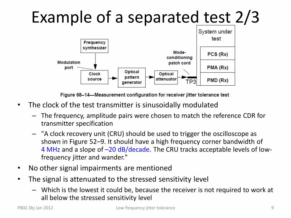
• The clock of the test transmitter is sinusoidally modulated
– The frequency, amplitude pairs were chosen to match the reference CDR for transmitter specification
– "A clock recovery unit (CRU) should be used to trigger the oscilloscope as shown in Figure 52–9. It should have a high frequency corner bandwidth of 4 MHz and a slope of –20 dB/decade. The CRU tracks acceptable levels of low-frequency jitter and wander."
• No other signal impairments are mentioned
• The signal is attenuated to the stressed sensitivity level
– Which is the lowest it could be, because the receiver is not required to work at all below the stressed sensitivity level
9 P802.3bj Jan 2012 Low frequency jitter tolerance
Example of a separated test 2/3

Example of a separated test 3/3
• A BER of better than 10–12 shall be achieved. – (This isn't a SONET style jitter tolerance test – only two
measurement points, no relative measurement)
• Various implementations may be used, provided that the resulting jitter matches that specified. Phase or frequency modulation may be applied to induce the sinusoidal jitter, and the modulation may be applied to the clock source or to the data stream itself.
10 P802.3bj Jan 2012 Low frequency jitter tolerance

Patterns, electrical test, other PHYs
• 68.6.1 Test patterns and related subclauses for optical parameters
• Pattern 1 (64B/66B-like, 8448 UI long) or 3 (PRBS31)
• 40GBASE-SR4, 100GBASE-SR10 follow the same approach as 10GBASE-LRM, for the same reasons
• The next two slides sketch out what an electrical version of 68.6.11 would involve. The backup slides detail what various PHYs and similar do – summarised in slides 3 and 4
P802.3bj Jan 2012 Low frequency jitter tolerance 11

Separated test – possible electrical version • Much of this is as for interference tolerance test, could be specified by reference,
without interference stress but with low frequency jitter
• Seek to allow use of product transmitter as test transmitter – This allows a rich, realistic, test pattern that may not be available in today's test
equipment
• Apply SJ to its clock reference
• Calibrate SJ out at the two spot frequencies – Because product may attenuate SJ
– This may need more jitter bandwidth in the test transmitter's clock multiplier than is needed for normal operation
– Spot frequencies depend on choice made for corner frequency for product transmitter jitter generation measurement
• With SJ at one of the two test condition, – Add a maximum-loss channel
• Maybe add broadband attenuation to adjust Tx amplitude range to minimum
– Connect to receiver under test
– Allow link bring-up including training as usual
– Measure BER • We had assumed that BER criterion would be the usual one. But see ghiasi_01_0113
• Repeat for other SJ test condition
• What else? P802.3bj Jan 2012 Low frequency jitter tolerance 12

Possible coefficients for separated test
• The blue numbers got from existing (black) specs by scaling by the jitter corner frequency, and rounding
• The red numbers are from comment 140
P802.3bj Jan 2012 Low frequency jitter tolerance 13
10GBASE-LRM 100GBASE-CR4/KR4 100GBASE-KP4 Unit
Signalling rate 10.3125 25.78125 13.59375 GBd
Jitter corner frequency or 3 dB frequency
4 10 5 1.36 MHz
Jitter frequency 75 190? 95? 25 kHz
SJpk-pk 5 5? 5? 5 UI
Jitter frequency 375 940? 470? 125 kHz
SJpk-pk 1 1? 1? 1 UI
BER 1e-12 1e-12/1e-5 1e-12/1e-5 . 1e-8

Questions • What Tx corner frequency is desired?
• Separated or combined Rx test?
• Will enough "product" Tx exist with CMU that track enough input jitter to output these amounts?
• What test pattern?
• Can test equipment deliver a suitable pattern?
• Any issues for calibrating a maximum loss channel?
• Other issues?
P802.3bj Jan 2012 Low frequency jitter tolerance 14
Backup
• Detail of jitter tolerance or similar specifications for the PHY types surveyed, more-or-less in clause order
• Looked at 1G and faster PHY types
P802.3bj Jan 2012 Low frequency jitter tolerance 15

PHYs and similar with low frequency jitter tolerance (combined test)
• 1000BASE-T – 40.6.1.2.5 Transmitter timing jitter
– 40.6.1.3.4 Alien Crosstalk noise rejection
– While receiving data from a transmitter specified in 40.6.1.2 through a link segment specified in 40.7 connected to all MDI duplex channels, a receiver shall send the proper PMA_UNITDATA.indication message to the PCS when...
• XAUI – 47.3.4.6 Jitter tolerance
– Test combines low frequency jitter mask and other jitters and minimum driver amplitude
– Figure 47–5—Single-tone sinusoidal jitter mask
• 10GBASE-S/L/E – 52.8.1 Sinusoidal jitter for receiver conformance test
– Figure 52–4—Mask of the sinusoidal component of jitter tolerance (informative)
– Table 52–19—Applied sinusoidal jitter
– Sinusoidal jitter is combined with other impairments including jitter
• 10GBASE-LX4 – 53.8.2 Receive jitter tolerance specification
– Sinusoidal jitter is added to other jitter and stress
• 10GBASE-T – 55.5.3.3 Transmitter timing jitter
– RMS period jitter over an integration time interval of 1 ms +/- 10%.
– 55.5.4 Receiver electrical specifications
– E.g. 55.5.4.4 While receiving data from a transmitter compliant with specifications in 55.5.3, through a 100 m link segment compliant with the specifications in 55.7, a receiver shall operate...
• 100BASE-LX10, 100BASE-BX10, 1000BASE-LX10, and 1000BASE-BX10, 1000BASE-PX10, 1000BASE-PX20, 10GBASE–PR, 10/1GBASE–PRX – Figure 58–10—Mask of the sinusoidal component of jitter tolerance (informative)
– Table 58–13—Applied sinusoidal jitter
– f2, jitter corner frequency, in the tables for the various PHYs P802.3bj Jan 2012 Low frequency jitter tolerance 16

802.3ap Backplane PHYs • 10GBASE-KX4
– 71.7.1.9 Transmit jitter test requirements
– For the purpose of jitter measurement, the effect of a single-pole high-pass filter with a 3 dB point at 1.875 MHz is applied to the jitter.
– 71.7.2 Receiver characteristics
– 71.7.2.1 Receiver interference tolerance
– as described in Annex 69A
– Annex 69A (normative) Interference tolerance testing
– The signaling speed of the pattern generator shall be offset ±100 ppm relative to the nominal signaling speed of the port type being tested
– The random jitter shall be measured at the output of a single pole high-pass filter with cut-off frequency at 1/250 of the signaling speed
– [No mention of low-frequency sinusoidal jitter]
• 10GBASE-KR – 72.7.1.8 Transmit jitter test requirements
– For the purpose of jitter measurement, the effect of a single-pole high-pass filter with a 3 dB point at 4 MHz is applied to the jitter.
– 72.7.2.1 Receiver interference tolerance
– as described in Annex 69A
• 40GBASE-KR4 – 84.8 40GBASE-KR4 electrical characteristics
– 84.8.1 Transmitter characteristics
– ... same as 10GBASE-KR, as detailed in 72.7.1.1 through 72.7.1.11.
– 84.8.2.1 Receiver interference tolerance
– ... same as those described for 10GBASE-KR in 72.7.2.1 and Annex 69A
P802.3bj Jan 2012 Low frequency jitter tolerance 17

802.3ba (See next slide for XLAUI/CAUI)
• 40GBASE-CR4 and 100GBASE-CR10 – Table 85–5—Transmitter characteristics at TP2 summary
– fTotal jitter at a BER of 10–12 measured per 83A.5.1
– 83A.5.1 Transmit jitter
– For the purpose of jitter measurement, the effect of a single-pole high-pass filter with a 3 dB point at 4 MHz is applied to the jitter
– 85.8.4.2 Receiver interference tolerance test
– [No mention of low-frequency sinusoidal jitter]
• 40GBASE-SR4 and 100GBASE-SR10 – Table 86–12—Test patterns and related subclauses
– Receiver jitter tolerance 3 (PRBS31) or 5 (scrambled idle)
– 86.8.4.8 Receiver jitter tolerance
– Receiver jitter tolerance shall be as defined as in 68.6.11, with the following differences...
• 40GBASE–LR4 – 87.8.11.1 Stressed receiver conformance test block diagram
– signal is conditioned (stressed) ... and has sinusoidal jitter applied as specified in 87.8.11.4.
– The sinusoidally jittered clock represents other forms of jitter and also verifies that the receiver under test can track low-frequency jitter
– 87.8.11.4 Sinusoidal jitter for receiver conformance test
– The amplitude of the applied sinusoidal jitter is dependent on frequency as specified in Table 87–13 and is illustrated in Figure 87–5
• 100GBASE–LR4 and 100GBASE–ER4 – 88.8.10 Stressed receiver sensitivity
– using the method defined in 87.8.11 with the following exceptions:
– a) Added sinusoidal jitter is as specified in Table 88–13...
P802.3bj Jan 2012 Low frequency jitter tolerance 18

More 802.3ba, 802.3bg
• XLAUI/CAUI – 83A.3.4.6 Jitter tolerance
– The XLAUI/CAUI receiver shall tolerate sinusoidal jitter with any frequency and amplitude defined by the mask of Figure 83A–12. This subcomponent of deterministic jitter is intended to ensure margin for low-frequency jitter, wander, noise, crosstalk, and other variable system effects
– 83A.5.2 Receiver tolerance
– The XLAUI/CAUI jitter tolerance test setup in Figure 83A–15 or its equivalent
– 83B.2.1 Module specifications
– Module input tolerance signal See 83A.5.2
– 83B.2.3 Host input signal tolerance
– sinusoidal jitter defined in 83A.3.4.6.
– Figure 83B–10—Stressed-eye and jitter tolerance test setup
• nPPI – The 0.05 UI Sinusoidal Jitter (SJ) component of J2 Jitter is defined for frequencies much higher than the CDR
bandwidth (e.g., ~20 MHz). At lower frequencies, the CDR must track additional applied SJ as detailed in the relevant specifications (see Figure 86A–10 and 52.8.1)
– Figure 86A–10—Mask of the sinusoidal component of jitter tolerance
– Table 86A–7—Applied sinusoidal jitter
• 40GBASE-FR – 89.7.10 Receiver jitter tolerance
– SONET style for dual-use (Ethernet and SONET) products
P802.3bj Jan 2012 Low frequency jitter tolerance 19