Low-cost Setup for Localized Semi-invasive Optical Fault ... · PDF fileLow-cost Setup for...
38
Low-cost Setup for Localized Semi-invasive Optical Fault Injection Attacks Oscar M. Guillen 1 Michael Gruber 2 Fabrizio De Santis 2 1 Giesecke & Devrient 2 Technische Universit¨ at M¨ unchen COSADE 2017 Guillen, Gruber, De Santis (G&D,TUM) April 13-14, 2017 1 / 27
Transcript of Low-cost Setup for Localized Semi-invasive Optical Fault ... · PDF fileLow-cost Setup for...
Low-cost Setup for Localized Semi-invasiveOptical Fault Injection Attacks
Oscar M. Guillen1 Michael Gruber2 Fabrizio De Santis2
1 Giesecke & Devrient2 Technische Universitat Munchen
COSADE 2017
Guillen, Gruber, De Santis (G&D,TUM) April 13-14, 2017 1 / 27

Table of contents
1 IntroductionMotivationFault Injection Techniques
2 Evaluation FrameworkFault Injection SetupPreparationFault Characterization
3 Application to SpeckSimon and SpeckInstruction SkipRandom Fault
4 Summary
Guillen, Gruber, De Santis (G&D,TUM) April 13-14, 2017 2 / 27

Motivation
Fault Injection in practice:I Are local optical attacks feasible using low cost equipment (∼ e500)?I What kind of faults can be generated?
Guillen, Gruber, De Santis (G&D,TUM) April 13-14, 2017 3 / 27

Motivation
The cost of the equipment is important for security evaluation
Attack ratingI EquipmentI Level of expertise
Low-cost devicesI Microcontroller-based devicesI IoT endpoints
Guillen, Gruber, De Santis (G&D,TUM) April 13-14, 2017 4 / 27

Fault Injection Techniques
Technique Accuracy Accuracy Cost Risk(Spatial) (Temporal) (Damage)
Clock glitch none high low noneVoltage spike none high low lowHeat low none low lowEM Pulse medium medium medium mediumLaser beam high high high medium
Table : Summary of non-invasive fault injection techniques [1]
Guillen, Gruber, De Santis (G&D,TUM) April 13-14, 2017 5 / 27

Optical Fault Injection
Complete fault injection stations cost up to e150k [3]
Light sourceI Flashgun, for older technology nodes [6]I Laser, newer technologies
Focusing elementI Visible-light microscopeI Infrared microscope and camera
PositioningI X-Y Stage
Guillen, Gruber, De Santis (G&D,TUM) April 13-14, 2017 6 / 27

Low-cost Optical Fault Injection
Our low-cost fault injection setup ∼ e500
Light sourceI Flashgun
Focusing elementI Ball lens ’microscope’
PositioningI X-Y Micro-milling stage (5 µm resolution)I Motor control using grbl [5]I Z-axis operated manually
DUT’s minimal setup boardsI AVR 8-bit,
Atmega328p, 350 nmI ARM Cortex M0 32-bit,
STM32F030F4P6, 90 nm
Guillen, Gruber, De Santis (G&D,TUM) April 13-14, 2017 7 / 27
Table of contents
1 IntroductionMotivationFault Injection Techniques
2 Evaluation FrameworkFault Injection SetupPreparationFault Characterization
3 Application to SpeckSimon and SpeckInstruction SkipRandom Fault
4 Summary
Guillen, Gruber, De Santis (G&D,TUM) April 13-14, 2017 7 / 27

Block Diagram
PC Debugger
Control Board
XY-Table
DUT
Flashgun
SWDUSB
USB / UART
USB / UART
USB / UART
Trigger Reset
Trigger
Guillen, Gruber, De Santis (G&D,TUM) April 13-14, 2017 8 / 27

Fault Injection Setup
XY-TablePower Supply
Control Board
Flash Gun
CNC Board
Debugger
DUT
Guillen, Gruber, De Santis (G&D,TUM) April 13-14, 2017 9 / 27

Fault Injection Setup
XY-TablePower Supply
Control Board
Flash Gun
CNC Board
Debugger
DUT
Guillen, Gruber, De Santis (G&D,TUM) April 13-14, 2017 9 / 27
Fault Injection Setup
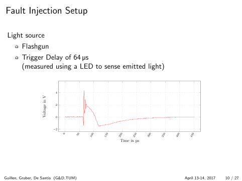
Light source
Flashgun
Trigger Delay of 64 µs(measured using a LED to sense emitted light)
0 50 100
150
200
250
300
350
400
450
−2
0
2
4
Time in µs
Voltage
inV
Guillen, Gruber, De Santis (G&D,TUM) April 13-14, 2017 10 / 27

3D Printed Mount for the Optics
(a) Side I (b) Side II
(c) Top (d) Bottom
Guillen, Gruber, De Santis (G&D,TUM) April 13-14, 2017 11 / 27

Optics
Ball Lens
Diameter 1 mm
Substrate N-BK7
Wavelength 350 nm to2200 nm
Diameter Tolerance ±2.5 µm
Back Focal Length (BFL)0.23 mm
Mounted in 3d printed socketFront-View
Guillen, Gruber, De Santis (G&D,TUM) April 13-14, 2017 12 / 27

Optics
Ball Lens
Diameter 1 mm
Substrate N-BK7
Wavelength 350 nm to2200 nm
Diameter Tolerance ±2.5 µm
Back Focal Length (BFL)0.23 mm
Mounted in 3d printed socketTop-View
Guillen, Gruber, De Santis (G&D,TUM) April 13-14, 2017 12 / 27

Ball lens
R
d
f
BFL
Ball lens focal point,
1
f=
4(n − 1)
n · d(1)
The magnification M of a lenscompared to a human eye is:
M =250 mm
f(2)
for a 1.0 mm diameter, N-BK7 borosilicate-glass ball lens n = 1.517f = 0.733 56 mm, BFL = 0.233 56 mm, M = 340×
Guillen, Gruber, De Santis (G&D,TUM) April 13-14, 2017 13 / 27

Ball lens
R
d
fr
white light ray
fbfb
White light is composed ofdifferent wavelengths
Light components aredispersed according to theirfrequency (chromaticaberration)
Infrared component(wavelength >715 nm) ispresent in the light generatedby the flashgun and focusedthrough the ball lens
Guillen, Gruber, De Santis (G&D,TUM) April 13-14, 2017 13 / 27
Preparation I
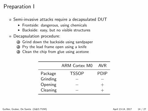
Semi-invasive attacks require a decapsulated DUTI Frontside: dangerous, using chemicalsI Backside: easy, but no visible structures
Decapsulation procedure:1 Grind down the backside using sandpaper2 Pry the lead frame open using a knife3 Clean the chip from glue using acetone
ARM Cortex M0 AVR
Package TSSOP PDIPGrinding − −Opening − +Cleaning − +
Guillen, Gruber, De Santis (G&D,TUM) April 13-14, 2017 14 / 27

Preparation II
(a) Sanding (b) Removing (c) Cleaning
Guillen, Gruber, De Santis (G&D,TUM) April 13-14, 2017 15 / 27

Fault Characterization I
Instruction Skip Test(global/local)
1 Execute function2 Inject fault3 Check result
RAM Faults (global/local)1 Write pattern to RAM2 Inject fault3 Check result
Register Faults (local)1 Pre-set user accessible
registers2 Inject fault3 Read back registers
Procedure:1 Generate meander pattern2 Perform test3 Read result4 Update position5 goto #2
Guillen, Gruber, De Santis (G&D,TUM) April 13-14, 2017 16 / 27
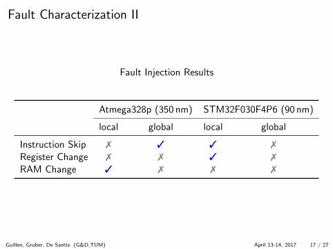
Fault Characterization II
Fault Injection Results
Atmega328p (350 nm) STM32F030F4P6 (90 nm)
local global local global
Instruction Skip 7 3 3 7
Register Change 7 7 3 7
RAM Change 3 7 7 7
Guillen, Gruber, De Santis (G&D,TUM) April 13-14, 2017 17 / 27

Fault Characterization III
ARM Cortex M0 32-bit, 90 nm, (STM32F030F4P6)Reset, No change, Exploitable fault, Non-exploitable fault
(a) Whole Chip, 0.1mm, 3mm× 3mm (b) ROI-1, 0.05mm, 1.5mm× 1.5mm
Guillen, Gruber, De Santis (G&D,TUM) April 13-14, 2017 18 / 27

Fault Characterization IV
ARM Cortex M0 32-bit, 90 nm, (STM32F030F4P6)Reset, No change, Exploitable fault, Non-exploitable fault
(c) ROI-2, 0.02mm, 0.4mm× 0.4mm (d) ROI-3, 0.015mm, 0.4mm× 0.4mm
Guillen, Gruber, De Santis (G&D,TUM) April 13-14, 2017 19 / 27

Table of contents
1 IntroductionMotivationFault Injection Techniques
2 Evaluation FrameworkFault Injection SetupPreparationFault Characterization
3 Application to SpeckSimon and SpeckInstruction SkipRandom Fault
4 Summary
Guillen, Gruber, De Santis (G&D,TUM) April 13-14, 2017 19 / 27

Simon and Speck
Published by the NSA in 2013 [2]
Lightweight block ciphers
Perform well on resource constrained devices
Simon targets HW implementations
Speck targets SW implementations
Each algorithm allows 10 different combinations of block/key size
block size key size
32 6448 72, 9664 96, 12896 96, 114128 128, 192, 256
Guillen, Gruber, De Santis (G&D,TUM) April 13-14, 2017 20 / 27

Details of Speck
Feistel-like structure
ADD, ROT, XOR (ARX)
T 22-34 rounds
Break the 2,3,4 last rounds torecover key, depending on keysize
Key Schedule reuses the roundfunction
State yT−1 known
xi yi
xi+1 yi+1
≫ α
≪ β
+
ki
R(x , y) = (f (x , y) ⊕ k , y ≪ β ⊕ f (x , y) ⊕ k) where f (x , y) = x ≫ α+ y
Guillen, Gruber, De Santis (G&D,TUM) April 13-14, 2017 21 / 27

Application to Speck I
What kind faults can we generate?
What kind of faults can we exploit?
Guillen, Gruber, De Santis (G&D,TUM) April 13-14, 2017 22 / 27

Application to Speck II
Instruction Skip
AVR - global setup
STM32 - local setup
Skip XOR with kT−1
Less than 1 second
Only 1 injection needed
Recover kT−1 completely
Same outcome in 80 % of theinjections
xT−1 yT−1
xT yT
≫ α
≪ β
+
kT−1
Guillen, Gruber, De Santis (G&D,TUM) April 13-14, 2017 23 / 27

Application to Speck II
Instruction Skip
AVR - global setup
STM32 - local setup
Skip XOR with kT−1
Less than 1 second
Only 1 injection needed
Recover kT−1 completely
Same outcome in 80 % of theinjections
xT−1 yT−1
xT yT
≫ α
≪ β
+
kT−1
Guillen, Gruber, De Santis (G&D,TUM) April 13-14, 2017 23 / 27

Application to Speck III
Random Fault/Register Fault [4]
STM32 - local setup
Random fault model at yT−1
Attack takes ≈1 h
Attack needs≈3 × 10³ injections
46 faulty pairs recovered
Recovers n − 1 bits of kT−1
(MSB cannot be recovered dueto the modular addition)
xT−1 yT−1
xT yT
≫ α
≪ β
+
kT−1
Guillen, Gruber, De Santis (G&D,TUM) April 13-14, 2017 24 / 27

Table of contents
1 IntroductionMotivationFault Injection Techniques
2 Evaluation FrameworkFault Injection SetupPreparationFault Characterization
3 Application to SpeckSimon and SpeckInstruction SkipRandom Fault
4 Summary
Guillen, Gruber, De Santis (G&D,TUM) April 13-14, 2017 24 / 27

Summary
Low cost localized fault injection setupI https://github.com/open-fi/fault-injector
Backside fault injectionI Cheap ball lens enables backside attacks with flashgunI Performed in unthinned devices
Faults observed on 90 nm MCUsI Register manipulationI Instruction skip
Implications
High security devices might already have countermeasures in place(e.g. optical sensors)
Low-cost, microcontroller-based, devices should consider low-costoptical attacks as a serious threat
Guillen, Gruber, De Santis (G&D,TUM) April 13-14, 2017 25 / 27

Future Work
Different light sources
Different types and sizes of focusing elements
Pattern-based triggering
EM Fault Injection
Guillen, Gruber, De Santis (G&D,TUM) April 13-14, 2017 26 / 27

Costs
Function Description Price (EUR)
OpticsFlashgun YN560 III 60Ball lens 1 mm N-BK7 25
PositioningX-Y Table Proxxon KT 70 263Stand Proxxon Stand 70Control Arduino UNO 20Drivers DRV8825 18
Control and DebuggingControl Board STM32 Nucleo F411RE 12Debugger STM32 Nucleo F411RE (OpenOCD) 12
MiscellaneousSand paper, mask, latex gloves, acetone 26
506
Guillen, Gruber, De Santis (G&D,TUM) April 13-14, 2017 27 / 27

Thank you for your attention!
Guillen, Gruber, De Santis (G&D,TUM) April 13-14, 2017 27 / 27
Bibliography
[1] Alessandro Barenghi, Luca Breveglieri, Israel Koren, and David Naccache. Fault injection attacks on cryptographic devices:Theory, practice, and countermeasures. Proceedings of the IEEE, 100(11):3056–3076, 2012.
[2] Ray Beaulieu, Douglas Shors, Jason Smith, Stefan Treatman-Clark, Bryan Weeks, and Louis Wingers. The simon and speckfamilies of lightweight block ciphers. Cryptology ePrint Archive, Report 2013/404, 2013. http://eprint.iacr.org/.
[3] Jakub Breier and Dirmanto Jap. Testing feasibility of back-side laser fault injection on a microcontroller. In Proceedings ofthe WESS’15: Workshop on Embedded Systems Security, WESS’15, pages 5:1–5:6, New York, NY, USA, 2015. ACM.ISBN 978-1-4503-3667-3. doi: 10.1145/2818362.2818367. URL http://doi.acm.org/10.1145/2818362.2818367.
[4] Yuming Huo, Fan Zhang, Xiutao Feng, and Li-Ping Wang. Improved differential fault attack on the block cipher speck. In2015 Workshop on Fault Diagnosis and Tolerance in Cryptography (FDTC), pages 28–34. IEEE, 2015.
[5] Sungeun K. Jeon, 2016. https://github.com/grbl/grbl.
[6] Sergei P. Skorobogatov and Ross J. Anderson. Optical fault induction attacks. In Cryptographic Hardware and EmbeddedSystems - CHES 2002, 4th International Workshop, Redwood Shores, CA, USA, August 13-15, 2002, Revised Papers, pages2–12, 2002. doi: 10.1007/3-540-36400-5 2. URL http://dx.doi.org/10.1007/3-540-36400-5_2.
Guillen, Gruber, De Santis (G&D,TUM) April 13-14, 2017 27 / 27

Guillen, Gruber, De Santis (G&D,TUM) April 13-14, 2017 27 / 27