Low Cost 3G Enabled Data Logger for Photovoltaic Systems · Low Cost 3G Enabled Data Logger for...
107
Low Cost 3G Enabled Data Logger for Photovoltaic Systems Christopher Tapper u4673327 Supervised by Nicholas Engerer October 2014 A thesis submitted in part fulfilment of the degree of Bachelor of Engineering Department of Engineering Australian National University
-
Upload
nguyentuyen -
Category
Documents
-
view
223 -
download
0
Transcript of Low Cost 3G Enabled Data Logger for Photovoltaic Systems · Low Cost 3G Enabled Data Logger for...
Low Cost 3G Enabled Data Logger for Photovoltaic Systems
Christopher Tapper
u4673327
Supervised by Nicholas Engerer
October 2014
A thesis submitted in part fulfilment of the degree of
Bachelor of Engineering
Department of Engineering
Australian National University

!

!
This thesis contains no material which has been accepted for the award of any
other degree or diploma in any university. To the best of the author’s
knowledge, it contains no material previously published or written by another
person, except where due reference is made in the text.
Christopher Tapper
31 October 2014
© Christopher Tapper

! i
ABSTRACT
To support the collaborative advanced solar forecasting project being undertaken by ANU
and NICTA, a prototype data logger for an SMA 1600TL inverter was designed and
implemented. By using supporting documentation from SMA in conjunction with open-
source packet sniffing software called Wireshark, it was possible to reverse engineer the
proprietary communication protocols used by SMA. The data logger was then
implemented using low cost Arduino prototyping hardware. The design can successfully
request data from the inverter and log it to an SD card, as well as uploading it to an offsite
server via FTP over a GPRS data connection.

! ii
CONTENTS
ABSTRACT' I!
LIST'OF'FIGURES' V!
LIST'OF'TABLES' VI!
LIST'OF'CODE'SNIPPETS' VIII!
CHAPTER'1! INTRODUCTION' 1!
1.1! CONTEXT' 1!1.2! GOALS/SCOPE' 2!1.3! EXISTING'SOLUTIONS'AND'PREVIOUS'WORK' 2!
CHAPTER'2! HARDWARE' 4!
2.1! ARDUINO'UNO' 4!2.2! RS485'SHIELD' 5!2.3! GPRS/GSM'SHIELD' 7!2.4! SD'CARD'MODULE' 9!2.5! HARDWARE'CONCLUSION' 10!
CHAPTER'3! PROTOCOLS' 12!
3.1! SMA'NET' 12!3.1.1! SMA!NET!FRAME!FORMAT! 13!3.1.2! ESCAPE!CHARACTERS! 14!3.1.3! CHECKSUM! 14!3.1.4! ‘MAGIC’!BYTES! 14!3.2! SMA'DATA' 14!3.2.1! DATAGRAM!FORMAT! 15!3.2.2! COMMANDS! 16!3.2.3! NETWORK!CONFIGURATION! 20!3.2.4! REQUESTING!DATA! 21!
CHAPTER'4! METHODOLOGY'AND'IMPLEMENTATION' 22!4.1! IDENTIFYING'COMMUNICATION'PROTOCOLS' 22!4.1.1! INTERFACING!WITH!THE!INVERTER! 22!4.1.2! SUNNY!DATA!CONTROL! 23!4.1.3! WIRESHARK!AND!USBPCAP! 25!

! iii
4.1.4! NETWORK!CONFIGURATION!CAPTURED!BY!USBPCAP! 25!4.1.5! DATA!REQUEST!CAPTURED!BY!USBPCAP! 28!4.1.6! ARDUINO!SERIAL!ECHO! 32!4.2! IMPLEMENTATION'OF'PROTOCOLS'AND'RS485'COMMUNICATION' 32!4.2.1! DATA!STRUCTURES! 32!4.2.2! CREATING!SMA!DATA!PACKETS! 33!4.2.3! CALCULATING!CHECKSUMS! 34!4.2.4! SENDING!DATA!TO!THE!INVERTER! 34!4.2.5! RECEIVING!DATA!FROM!THE!INVERTER! 35!4.2.6! PARSING!RECEIVED!DATA! 36!4.3! COMMUNICATING'WITH'AND'CONTROLLING'THE'GPRS/GSM'SHIELD' 36!4.3.1! AT!COMMANDS! 37!4.3.2! SENDING!AT!COMMANDS! 38!4.3.3! INITIALISING!THE!GPRS/GSM!SHIELD! 39!4.3.4! CONFIGURING!BEARER!AND!FTP!SETTINGS! 40!4.3.5! OPENING!AN!FTP!SESSION! 40!4.4! LOGGING'DATA' 41!4.4.1! SD!CARD! 41!4.4.2! FTP!UPLOADS! 42!4.5! COMPLETE'SOFTWARE' 42!4.6! CALCULATING'AVERAGE'POWER'FROM'DATA' 43!
CHAPTER'5! RESULTS' 44!5.1! EXAMPLE'DATA' 44!
CHAPTER'6! CONCLUSIONS'AND'FUTURE'WORK' 46!6.1.1! CONCLUSION! 46!6.1.2! FUTURE!WORK! 46!
REFERENCES' 48!
APPENDIX' 50!
A.1'FCS_EEPROM_SETUP.INO' 50!A.2'SMA_DATA_LOGGER.INO' 53!A.3'FCS.INO' 60!A.4'GSM.INO' 62!A.5'RS485COMMS.H' 70!A.6'RS485COMMS.INO' 72!

! iv
A.7'DATAPACKETMAKER.INO' 80!A.8'SMA_DEFS.H' 84!A.9'USERDATAPARSING.INO' 86!A.10'EXAMPLE'SERIAL'OUTPUT'FROM'DATA'LOGGER' 91!A.11'RAW'DATA'LOG'FROM'2014F10F19'TO'2014F10F20' 93!

! v
LIST OF FIGURES
Figure 1: Arduino Uno R3 ....................................................................................................... 4!
Figure 2: DFRobot RS485 Shield ............................................................................................ 6!
Figure 3: Bottom of DFRobot GPRS/GPS/GSM Shield v3.0 with digital pins 0 and 1
(highlighted in red) bent to the side to bypass connection to the Arduino board. ......... 8!
Figure 4: DFRobot GPRS/GPS/GSM Shield v3.0 with digital pins 0 and 1 rewired to pins 8
and 9 (highlighted by the red rectangle). ........................................................................ 8!
Figure 5: SD Card module with 2GB SD card. ...................................................................... 10!
Figure 6: Complete data logger prototype, including breadboard for the SD Card module.11!
Figure 7: Escape character insertion example ...................................................................... 14!
Figure 8: Channel type bit description (SMA 2003) ............................................................ 18!
Figure 9: Channel data format field description (SMA 2003) ............................................. 18!
Figure 10: SMA 1600TL RS485 screw terminals .................................................................. 23!
Figure 11: Sunny Data Control serial port settings ............................................................... 24!
Figure 12: Sunny Data Control communication settings ...................................................... 24!
Figure 13: Network configuration packets captured by USBPcap ....................................... 26!
Figure 14: Data request packets captured by USBPcap ........................................................ 29!
Figure 15: Sunny Data Control logged values ...................................................................... 30!
Figure 16: Average power and cumulative energy generated 19th of October 2014 ............ 44!
Figure 17: Average power and cumulative energy generated 20th of October 2014 ........... 45!
! vi
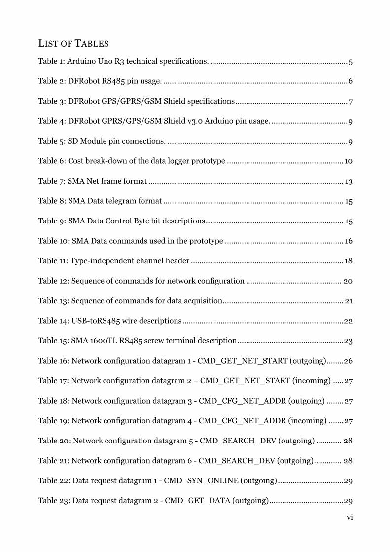
LIST OF TABLES
Table 1: Arduino Uno R3 technical specifications. ................................................................. 5!
Table 2: DFRobot RS485 pin usage. ....................................................................................... 6!
Table 3: DFRobot GPS/GPRS/GSM Shield specifications ..................................................... 7!
Table 4: DFRobot GPRS/GPS/GSM Shield v3.0 Arduino pin usage. .................................... 9!
Table 5: SD Module pin connections. ..................................................................................... 9!
Table 6: Cost break-down of the data logger prototype ....................................................... 10!
Table 7: SMA Net frame format ............................................................................................ 13!
Table 8: SMA Data telegram format ..................................................................................... 15!
Table 9: SMA Data Control Byte bit descriptions ................................................................. 15!
Table 10: SMA Data commands used in the prototype ........................................................ 16!
Table 11: Type-independent channel header ........................................................................ 18!
Table 12: Sequence of commands for network configuration ............................................. 20!
Table 13: Sequence of commands for data acquisition ......................................................... 21!
Table 14: USB-toRS485 wire descriptions ............................................................................ 22!
Table 15: SMA 1600TL RS485 screw terminal description .................................................. 23!
Table 16: Network configuration datagram 1 - CMD_GET_NET_START (outgoing) ........ 26!
Table 17: Network configuration datagram 2 – CMD_GET_NET_START (incoming) ..... 27!
Table 18: Network configuration datagram 3 - CMD_CFG_NET_ADDR (outgoing) ........ 27!
Table 19: Network configuration datagram 4 - CMD_CFG_NET_ADDR (incoming) ....... 27!
Table 20: Network configuration datagram 5 - CMD_SEARCH_DEV (outgoing) ............ 28!
Table 21: Network configuration datagram 6 - CMD_SEARCH_DEV (outgoing) ............. 28!
Table 22: Data request datagram 1 - CMD_SYN_ONLINE (outgoing) ............................... 29!
Table 23: Data request datagram 2 - CMD_GET_DATA (outgoing) ................................... 29!

! vii
Table 24: Data request datagram 3 - CMD_GET_DATA (incoming) ................................. 30!
Table 25: Assumed data request field values and byte positions by comparing datagrams to
Sunny Data Control ........................................................................................................ 31!
Table 26: AT Commands used by the data logger ................................................................ 37!

! viii
LIST OF CODE SNIPPETS
Code Snippet 1: makeCMD_GET_DATA() ........................................................................... 33!
Code Snippet 2: Function prototypes for writing to the RS485 serial connection .............. 34!
Code Snippet 3: Waiting for the transmit buffer of the UART to empty ............................. 35!
Code Snippet 4: Function prototypes for receiving and parsing SMA data ......................... 35!
Code Snippet 5: Parsing the data field of a CMD_CFG_NETADR response packet ........... 36!
Code Snippet 6: Function prototypes for sending AT Commands ....................................... 39!
Code Snippet 7: uploadFTP() function prototype ................................................................ 41!
Code Snippet 8: Writing data to the SD card ........................................................................ 41!
Code Snippet 9: Uploading data via FTP .............................................................................. 42!

! 1
Chapter 1 INTRODUCTION
1.1 CONTEXT
Photovoltaic (PV) technology is a potentially inexpensive, effective, and clean method
of power generation for Australia’s future; however, the inherently variable nature of
solar radiation remains problematic. The power output of PV systems is intermittent
due to both this variability and the diurnal nature of the sun (Sayeef et al. 2012), with
the primary source of uncertainty driven by clouds. This can become prohibitive
when a large area (e.g. a suburb) receives more than 20% of its power from PV
systems (Sayeef et al. 2012). During periods when the power output from grid-
feeding PV systems suddenly drops, a rapid response is required from grid operators
to provide alternate sources of energy generation (Williamson, 2012). However, to
date in Australia there are currently no proven methods for successfully forecasting
when such a period might occur. To address this problem, The Australian National
University (ANU), National ICT Australia (NICTA) and several Australian and
international partners have initiated an advanced solar forecasting project which will
provide short term forecasts of the expected power output from distributed PV
arrays.
One of the primary sources of data for this project is PV system power output
obtained by a data logger. This allows the panels to be used as a sensor to detect the
amount of solar radiation arriving at the panels. This data will then be used in
conjunction with cloud imagery and machine learning techniques to provide a short-
term forecast of the power output of PV systems over a large area such as a suburb. It
is planned for these data loggers to be deployed to up to 300 locations in the
Canberra region. While there currently are data loggers available on the market for
use with PV inverters, there are several problems with the existing technology. First,
they are often prohibitively expensive - often costing $1000 - $5000 per unit
(Williamson, 2012). Secondly, the majority of such devices depend on wireless
network connections to report the data, rather than mobile broadband, which limits
their relevance for an operational sensor network. Third, although there are some
options that utilize mobile broadband connections (e.g. eSquid), none of these units
communicate directly with the inverter, but instead use a current clamp to estimate
the power output via an assumed voltage. These units are not as accurate as they
assume there to be a constant voltage and do not communicate directly with the

! 2
inverter. This has severely limited the deployment of such hardware. The aim of this
project is to develop a relatively inexpensive data logger, which communicates
directly with a selected inverter type, and reports the logged data over a mobile
broadband network. Such sensors could then be deployed to PV inverters around the
Canberra region to acquire data to be used in the solar forecasting project.
SMA is the largest manufacturer of photovoltaic inverters in the world, and held
approximately 13% share of the global market in 2013 (SMA, 2014). Due to the
widespread usage of these inverters, this thesis project was initiated to develop a data
logger for them.
1.2 GOALS/SCOPE
The initial scope of the project was to design and implement a low cost data logger
with the capability to communicate with an SMA1600L Inverter. This inverter has
been installed on the rooftop of the Engineering Building at ANU as part of the solar
forecasting project. The communication with the inverter should be performed over
the RS485 serial interface. The device should log the average power output over five
minute periods, store the information locally and then transmit it back to the offsite
server. Initially, all wireless communications were to be performed over a GSM
network using text messages.
1.3 EXISTING SOLUTIONS AND PREVIOUS WORK
The Sunny WebBox is a monitoring and data logging device developed by SMA for
their line of PV inverters. It has the capability to log data from multiple inverters and
transfer this data to server via the user’s personal internet connection. With the
addition of a Sunny SensorBox to the system it is also possible to directly measure
solar radiation. These features meet the requirements for the data logger, however
due to the high cost (AUD$500 - $800 for the Sunny WebBox, and an additional
$476 - $600 for the Sunny SensorBox), and requiring the user’s personal internet
connection rather than a 3G connection, it is not an appropriate solution to the
problem.
YASDI (Yet Another SMA Data Implementation) is an open source program provided
by SMA that demonstrates an implementation of the SMA Net and SMA Data
protocols. The software is written in the C programming language which is
compatible with the Arduino hardware used for this project; however, it was not

! 3
possible to simply port the code due to it being designed to be run on a full operating
system rather than a microcontroller. One option would be to use an inexpensive PC
running YASDI in conjunction with a data logging application; however, the cost and
power consumption of such a set-up would both be higher than that of the data logger
that has been prototyped for this project.
The eSquid is an Arduino-based data logger manufactured by Canberra company IT
Suppliers and is a potential candidate device for the solar forecasting project. This
device uses current clamps to estimate the power output by multiplying the measured
current by an assumed constant voltage. Although the eSquid does have the capability
to communicate over a mobile phone network, it is not an ideal solution because it
cannot communicate directly with the inverters, and the constant voltage assumption
reduces the accuracy of the data.
ANU engineering student Leo Liu completed some initial work on the data logger
project in 2013. Liu’s thesis identifies possible hardware choices and outlines the
procedure for interfacing with the SMA1600L inverter via the RS485 serial interface.
There was also some initial work done on identifying the communication protocol
and communication procedures with the inverter. Liu also provides small programs
written in C that demonstrate the use of the various hardware components that will
be used in the data logger. Further information about his project and relevant code
can be obtained from his thesis document – a link to an online copy is provided in the
references of this thesis.

! 4
Chapter 2 HARDWARE
The data logger hardware consists of Arduino Uno R3 prototyping board with two
expansion boards (shields) stacked on top. The shields used for this project are a
DFRobot RS485 Shield and a DFRobot GPS/GPRS/GSM Shield. There is also an SD
card module connected to the board; however, this is a separate module and could
not be connected directly as a shield. The prototype data logger is powered by a
12V/2.5A plug-pack connected directly to the power input on the Arduino board. This
chapter will describe the various components and how they are connected.
2.1 ARDUINO UNO
The Arduino Uno (see Figure 1) is an open-source prototyping board powered by an
Atmel ATmega328 microcontroller. The board contains all the hardware that is
required to program and support the microcontroller, as well as providing a simple
method of adding extra capabilities and hardware through the use of expansion
boards (shields). The Arduino Uno was chosen for this project due to its low cost, low
power consumption, wide range of expansion boards, and its large quantity of open
source support libraries and example code. The specifications of this board are
detailed in
Table 1.
Figure 1: Arduino Uno R3

! 5
An official Arduino Uno R3 board costs USD$25 - 30 (AUD$28 - 35); however, due to
the open-source nature of the hardware there are various “clone” boards that are
100% compatible with the Arduino IDE and can cost as low as USD$11.95
(AUD$13.69). Additionally, all of the components are inexpensive, so if a custom PCB
(printed circuit board) implementation of the data logger was created the cost could
be lowered significantly.
Table 1: Arduino Uno R3 technical specifications.
Microcontroller ATmega328
Operating Voltage 5V
Input Voltage (recommended) 7-12V
Input Voltage (limits) 6-20V
Digital I/O Pins 14
Analog Input Pins 6
Flash Memory 32 KB (ATmega328); 0.5 KB used by Arduino
bootloader
SRAM 2 KB (ATmega328)
EEPROM 1 KB (ATmega328)
Clock Speed 16 MHz
2.2 RS485 SHIELD
Communication with the inverter is performed via an RS485 serial connection.
Another option was wireless communication via Bluetooth; however, there may have
been issues with the data logger and inverter reconnecting with each other in a
situation where one or both of the devices lose power. By default, the Arduino Uno
does not support RS485 but this capability was added through the use of a DFRobot
RS485 Shield (SKU: DFR0259; see Figure 2). This shield requires the use of 3 of the
digital I/O pins of the Arduino - the UART receive (RX) and transmit (TX) pins (0
and 1 respectively), and digital pin 2 to enable transmission (see Table 2). In addition,

! 6
the shield features a soldering area to make use of the free space on the PCB; this
could potentially be used as an area to attach the SD Card Module, which is currently
attached to a separate breadboard and wired to the Arduino. This expansion shield
costs USD$10.55 (AUD$12.09).
Table 2: DFRobot RS485 pin usage.
Digital I/O Pin Function
0 Receive (RX)
1 Transmit (TX)
2 RS485 transmit enable
There is a switch on this shield to change between automatic and manual
transmission. If the switch is set to automatic, data can be transmitted by writing
data to the transmit pin (pin 1) - pin 2 does not need to be set to HIGH. However, it
was decided for this project that the board should be operated in manual mode,
meaning that pin 2 should be enabled during data transmissions.
Figure 2: DFRobot RS485 Shield
Located on the back of the shield are the RS485 outputs. There are three possible
methods of connecting the RS485 wires - via the screw terminals, output pins on the
top of the board, or the PH2.0 2.omm connector. All three methods allow for the
connection of the four wires required for RS485 communications (signal wires A (+)

! 7
and B(-), GND and Vcc); however, only the signal wires and ground are required to be
connected for the data logger.
2.3 GPRS/GSM SHIELD
To add the capability to communicate via a data connection over a mobile phone
network a DFRobot GPS/GPRS/GSM Shield V3.0 (SKU: TEL0051) was added to the
data logger. This module was chosen due to its low power consumption, availability
and low cost. The board also has built in support for FTP (File Transmission
Protocol), greatly simplifying the transfer of data to the central server. Testing was
also performed with two other GPRS/GSM shields – the Sparkfun SM5100B GSM
Shield and the LinkSprite ATWIN Quad-band GPRS/GSM Shield; however, there
were issues with the Linksprite shield not responding to AT commands, and the
Sparkfun shield drew excessive current, requiring extra hardware to prevent the
shield from exceeding the maximum current draw of the voltage regulator on the
Arduino board. The DFRobot shield has neither of these issues and therefore is an
obvious solution to both of these problems. The GPRS/GSM shield chosen costs
USD$89.50 (AUD$102.03), making it the most expensive component of the data
logger. The specifications of the shield can be seen in Table 3.
Table 3: DFRobot GPS/GPRS/GSM Shield specifications
Power supply 6-12V
Power consumption 100mA at 7V (in GSM mode)
Frequencies EGSM 900MHz/DCS 1800MHz
GSM850 MHz/PCS 1900MHz
Antenna Embedded high-gain SMD antennas for
GPS & GSM
Control AT commands (GSM07.07 ,07.05 and
SIMCOM enhanced AT Commands)
SIM Card Standard (2FF; 25mm x 15mm)
By default, this shield communicates with the Arduino via the ATmega328’s UART on
the digital pins 0 (RX) and 1 (TX). However, the RS485 shield is already connected to

! 8
these two pins. The solution to this problem was to bend digital pins 0 and 1 on the
shield to the side so that they no longer connect to any of the other shields or the
Arduino (see Figure 3), and then connect the ports for digital pins 0 and 1 on the top
of the shield to digital pins 8 and 9 (see Figure 4). Data can now be transmitted to
this shield from the Arduino by using a software UART configured to use these 2 pins.
Figure 3: Bottom of DFRobot GPRS/GPS/GSM Shield v3.0 with digital pins 0 and 1 (highlighted in red) bent to the side to bypass connection to the Arduino board.
Figure 4: DFRobot GPRS/GPS/GSM Shield v3.0 with digital pins 0 and 1 rewired to pins 8 and 9 (highlighted by the red rectangle).
Three additional pins – digital pins 3, 4 and 5 - are required for configuring which
mode the board should be operating in (i.e. GPS or GSM) and the timing for the GSM
chip. A list of all the required pins is shown in Table 4.

! 9

! 10
Table 4: DFRobot GPRS/GPS/GSM Shield v3.0 Arduino pin usage.
Digital I/O Pin Function
3 Enable/disable GSM
4 Enable/disable GPS
5 Configure GSM timing
8 Transmit (TX)
9 Receive (RX)
2.4 SD CARD MODULE
Due the limited non-volatile memory of the Arduino Uno, additional hardware was
required to store the logged data locally. The most simple and cost-effective method
of local storage is the use of an SD card module. The module chosen is produced by
DFRobot (SKU: DFR0071) and requires the use of digital pins 10 - 13, in addition to
connecting to the GND and 5 volt pins to power the module. Because the board
requires connections to these additional two pins for power, it was not possible to
directly attach it to the shield stack of the data logger. Instead, it is attached to a
breadboard and wired to the required pins. For a more finalised prototype, this SD
Card Module could be attached to the soldering area on the RS485 shield.
Table 5: SD Module pin connections.
Pin (Arduino) Pin (SD Module)
10 (digital) SS
11 (digital) MOSI
12 (digital) MISO
13 (digital) SCK
GND GND
5V 5V
The prototype data logger uses a 2GB SD Card; however, due to the cost of solid-state
memory falling it would now be cheaper to purchase a larger SD card. This should

! 11
cost under AUD$10, bringing the total cost of SD module (USD$9.60, or AUD$10.94)
and SD card to a maximum of AUD$20.94. Storage capacity will not be an issue – in
the current prototype, the memory requirements of the data logged at each interval
(every 5 minutes) is at most 22 bytes. In the worst case scenario, assuming that data
is being logged 24 hours a day, a 2GB SD Card would provide enough memory to
store over 800 years of data.
Figure 5: SD Card module with 2GB SD card.
2.5 HARDWARE CONCLUSION
Table 6: Cost break-down of the data logger prototype
Component Cost (AUD)
Arduino Uno R3 $28
DFRobot RS485 Shield $12.09
DFRobot GPS/GSM/GPRS Shield $102.03
SD Card Module $10.94
SD Card $10 (maximum; varies with storage
capacity)
12V 2.5A power supply $29.95
Total: $193.01
The total cost of the prototype data logger, including the 12V 2.5A power supply, is
AUD$193.06. A break down of this cost can be seen in Table 6. This is approximately
38% of the minimum cost of an SMA Sunny WebBox, meeting the criteria that the
data logger should be relatively inexpensive. It is predicted that the cost for a mass-
produced PCB implementation of the data logger would be even less expensive;

! 12
however, further design and research would need to be performed to estimate this
exact cost.
Figure 6: Complete data logger prototype, including breadboard for the SD Card module.

! 13
Chapter 3 PROTOCOLS
Rather than using industry standard communication protocols, SMA has developed a
set of proprietary protocols for communicating with their PV inverters and data
loggers. These protocols roughly adhere to the design suggested by the Open Systems
Interconnections (OSI) model. The data link layer protocols are SMA Net and Sunny
Net, and the network/transport layer protocol is SMA Data. Sunny Net has since been
superseded by SMA Net, and hence it was decided that SMA Net should be
implemented as the data link protocol.
This chapter will describe the relevant protocol frame formats, commands, and
communication procedures. Further information and detail can be found in the SMA
Data Protocol Specification (SMA 2003).
3.1 SMA NET
SMA Net offers many advantages over SMA’s alternative data link protocol Sunny
Net, including:
• Sunny Net can only transfer SMA Data telegrams, while SMA Net is
compatible with multiple protocols, including many standard internet
protocols such as TCP/IP. The format of SMA Net frames also complies with
the Point-to-Point Protocol (PPP; RFC 1662) and the international High-Level
Data Link Control (HDLC; ISO 13239) standard.
• SMA Net features a safer checksum for the verification of the data contained
by the frame - Sunny Net used simple byte-by-byte addition of the telegram
content, while SMA Net uses a 16-bit cyclic redundancy check.
• The SMA Net frame has an overhead of only 8 bytes compared to Sunny Net’s
14 bytes.
• Sunny Net may not be used in future products manufactured by SMA.

! 14
3.1.1 SMA NET FRAME FORMAT
Table 7: SMA Net frame format
Frame Content Frame
Start Address Control Protocol
Header
SMA Data Checksum Stop
1 byte 1 byte 1 byte 2 bytes 7 – 262
bytes
2 bytes 1 byte
7E FF 03 7E
Start - This signifies the start of a new telegram frame. The value of this field should
always be 0x7E.
Address - This byte contains the address of the recipient of the SMA Net telegram.
This should always be set to the broadcast address 0xFF (i.e., the telegram is sent to
every device connected to the multi-drop RS485 serial connection; it is the
responsibility of the device to read the destination address from the encapsulated
SMA Data telegram to determine whether it is the intended recipient).
Control - This field should always be set to 0x03, signifying ‘unnumbered
information’ (SMA 2003).
Content - The first 2 bytes of this field contain the protocol identifier which can be
one of three values: 0x4041 for SMA Data Telegrams, 0x4051 for TCP/IP data, or
0x4043 for Software Update System (SUSy) data. This data logger uses SMA Data, so
this field should be set to 0x4041. The following 1498 bytes contains the headers and
data of higher level protocols; however, at most 262 of these bytes will be used by the
data logger, as this is the maximum size of an SMA Data datagram.
Checksum - This is the 16-bit checksum used for the verification of telegrams. The
16-bit value should be in little-endian format. See sections 3.1.3 and 4.2.3 for further
details on the calculation of this checksum.
Stop - This is a flag signifying the end of the telegram frame. The value should be set
to 0x7E.

! 15
3.1.2 ESCAPE CHARACTERS
There are cases when the data, in either the contents of the telegram or the checksum,
contains bytes that would interrupt the transfer of the telegram, such as the
start/stop byte 0x7E. If this occurs, an escape character 0x7D is inserted, followed by
the exclusive OR (XOR) of the offending byte and 0x20. For example, 0x7E is
transferred as 0x7D followed by the byte 0x5E (0x7E XOR 0x20), as seen in Figure 7.
Other characters that are escaped when they appear in data are 0x7D (only when it
appears in the data, not when it is already an escape character), 0x11, 0x12, and 0x13.
Before: 7e:ff:03:40:41:00:00:00:00:80:00:03:8f:fc:57:77:f3:00:7e:1d:7e
After: 7e:ff:03:40:41:00:00:00:00:80:00:03:8f:fc:57:77:f3:00:7d:5e:1d:7e
Figure 7: Escape character insertion example
3.1.3 CHECKSUM
The checksum used for SMA Net is a 16-bit cyclic redundancy check, with polynomial
!!" + !!" + !! + 1. The fields taken into account for the calculation are the address,
control, protocol and data fields. The checksum should be calculated prior to the
insertion of any escape characters.
3.1.4 ‘MAGIC’ BYTES
Before and after an SMA Net telegram is transmitted a pair of bytes must be sent to
the inverter. The bytes to be sent before a transmission are 0xAA, 0xAA; and the
bytes to be sent after are 0x55, 0x55. The reason for this is undocumented by SMA,
and was only discovered through experimentation (see Section 0). The inverter will
not respond to any commands if these bytes have not been sent.
3.2 SMA DATA
SMA Data is the network/transport layer protocol implemented by SMA. It is this
protocol that sends commands and transfers data between devices. This section will
detail the datagram format and the various commands that are of use to this project.

! 16
3.2.1 DATAGRAM FORMAT
Table 8: SMA Data telegram format
Header Data
Src Dest Ctrl Pkt Cnt Cmd Data
2 bytes 2 bytes 1 byte 1 byte 1 byte 0 – 255 bytes
Src (Source) - Source address of the datagram. All packets sent by the data logger
will have a source address of 0x00.
Dest (Destination) - Destination address of the datagram. This can either be the
address of a single device or a group of devices. If it is a group address, bit 7 of the
control byte must be set to 1.
Ctrl (Control) - The bits of this byte are used as flags to send various control signals
between devices. When the gateway blocking bit (4) is set, a connected data logger
should block the datagram. Bit 6 is used for acknowledgement of telegrams - an
inquiry should have this set to 0 and the response should set it to 1. The address
mode can be set to either a single device address or a group address by setting bit 7 to
0 or 1 respectively. Bits 0-3 and 5 are reserved and their function is not documented
by SMA.
Table 9: SMA Data Control Byte bit descriptions
Bit Flag
0 Reserved
1 Reserved
2 Reserved
3 Reserved
4 Gateway blocking. 0 = disabled / 1 = enabled
5 Reserved
6 Acknowledge. 0 = inquiry / 1 = response
7 Address mode. 0 = single device / 1 = group address

! 17
Pkt Cnt (Packet Count) - This field is used when performing bulk data transfers
(i.e., when the data cannot all fit in one SMA Data packet). If the datagram is a
response to an inquiry, this field contains the number of remaining packets. Each
subsequent packet must be requested by another inquiry packet by setting this count
to the value in the previously received packet.
Cmd (Command) - There is an extensive list of commands that can be sent to SMA
devices. The commands of interest to this project are listed in Section 3.2.2. All other
commands are documented in the SMA Data Protocol Specification.
Data - The data to be transferred by this packet. This field can be 0 - 255 bytes long,
with the contents depending on the command. Section 3.2.2 will provide more details
on the commands used for this project.
3.2.2 COMMANDS
This section lists and describes the SMA Data commands that are of use to this
project. Table 10 provides a summary of the commands and their function, which are
then described in further detail in the following paragraphs.
Table 10: SMA Data commands used in the prototype
Command number Name Description
02 CMD_SEARCH_DEV Search for devices
03 CMD_CFG_NETADR Set the network address of a device
06 CMD_GET_NET_START Start configuring the network
09 CMD_GET_CINFO Request input/output channel
information
10 CMD_SYN_ONLINE Synchronise online data
11 CMD_GET_DATA Request data from device
CMD_SEARCH_DEV - This command searches for a specific device by its serial
number. The data content of a CMD_SEARCH_DEV request packet is the 4 byte
serial number of the requested device in little-endian format. The ‘group address’ bit
of the control byte should be set to 1, as this command is sent to every device on the
network, but only the device with the matching serial number should respond.

! 18
The data in the response packet to this command is 12 bytes long and contains the 4
byte serial number of the device followed by the 8 character (8 byte) “device type”. If
the device type is less than 8 characters long it is padded with ASCII zeroes. The
source address of this response is the network address of the device, and the
destination address should be the destination address of the data logger that the
initial request was received from. The “acknowledgement” byte in the control field
should be set to signify that this is a response.
Examples of this command can be seen in Section 4.1.4 (Table 20 and Table 21).
CMD_CFG_NETADR - This command requests that a device on the network
should change its network address. The data content of an enquiry packet contains
the serial number of the device that should change its network address, followed by
the new network address to be assigned. This command is sent as a broadcast, so the
‘group address’ bit of the control byte should be set to 1.
If the destination device successfully changes its network address as requested, it will
respond with a packet that has the new network address as the source. The data
field will contain the serial number of the device. This can be cross-checked with the
serial number from the enquiry packet to confirm that the correct device has
responded.
Examples of this command can be seen in Section 4.1.4 (Table 18 and Table 19).
CMD_GET_NET_START - This command is used to begin network configuration.
It should only be sent by the data logger once at the beginning of the configuration
process. The request packet contains no data, and sends the request to every device
on the network, meaning that the address mode flag should be set to 1 (group
address). The devices on the network then respond with their serial number and
device type.
Examples of this command can be seen in Section 4.1.4 (Table 16 and Table 17).
CMD_GET_CINFO – This command requests the channel list from a device. The
channel list describes all the inputs and outputs that can be set or requested
respectively. The response from the inverter consists of a sequence of packets
containing the details about every channel. There are three possible types of
channels: analog, digital, counter, and status. Each of these types is transmitted with

! 19
a 23 byte type-independent channel header (see Table 11), followed by a type-
dependant description of the parameters of the channel.
Table 11: Type-independent channel header
Index Channel Type Data Format Fill Name
1 byte 2 bytes 2 bytes 2 bytes 16 bytes
Of particular interest is the channel type field for each channel. This field is mapped
directly to the channel mask that is sent as part of a data request, allowing particular
types of channels to be requested. The function of each bit of this two byte field is
shown in Figure 8.
Figure 8: Channel type bit description (SMA 2003)
Figure 9: Channel data format field description (SMA 2003)

! 20
Due to hardware limitations of the Arduino (lack of sufficient SRAM), it was not
possible to properly implement this command or channel lists. The total size of the
channel list from the inverter was approximately 8 KB, and the SRAM of the Arduino
is only 2 KB, making it impossible to store the entire list in a buffer for processing. An
alternative solution for finding the location of the required data in a packet was
devised, described in Section 4.1.5. Because it was not implemented, the format of the
command and its responses has not been described in full detail; more information
can be found in the SMA Data Protocol Specification.
CMD_SYN_ONLINE – This command is used to synchronise online data. The
purpose of this command is to save the values of each memory channel of the inverter
at the current time. This should be sent to the inverter prior to every data request to
ensure that the most up-to-date data is received. The data field of the packet contains
the current Epoch time (seconds since 1970-01-01 00:00:00 UTC) as a 4 byte integer.
An example of this command can be seen in Section 4.1.5 (Table 22).
CMD_GET_DATA – This command is used to request data from a device. The data
field consists of a 2-byte transfer mask, followed by the index of the channel to be
requested. If the index is set to zero, all channels that have a type that matches the
mask will be returned. There are additional parameters that can be added to the data
field that allow archived data to be requested; however, these are not of relevance to
this thesis and are covered extensively in the SMA Data Protocol Technical
Specification (2003).
The transfer mask is mapped exactly to the channel type returned for each channel as
described above (Figure 8). For example; if the we send a data request with transfer
mask 0x090F (00001001 00001111), we would be requesting all analog, digital,
counter and status channels that are either inputs or instantaneous values.
The response packet returns the values of each channel that matches this mask,
ordered by their index; however, this is all that is returned. Without knowledge of the
channel list (e.g. which channels match the transfer mask, the order of the channels
in the channel list, and the number of bytes data type of each channel), it is difficult
to determine what data has actually been returned. Because the channel list was not
implemented for the prototype data logger, an alternative method was devised for
correctly identifying the byte offset of the required data in the response packet. This
is described in Section 4.1.5.
! 21
Examples of this command can be seen in Section 4.1.5 (Table 23 and Table 24).
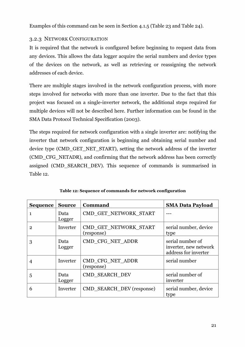
3.2.3 NETWORK CONFIGURATION
It is required that the network is configured before beginning to request data from
any devices. This allows the data logger acquire the serial numbers and device types
of the devices on the network, as well as retrieving or reassigning the network
addresses of each device.
There are multiple stages involved in the network configuration process, with more
steps involved for networks with more than one inverter. Due to the fact that this
project was focused on a single-inverter network, the additional steps required for
multiple devices will not be described here. Further information can be found in the
SMA Data Protocol Technical Specification (2003).
The steps required for network configuration with a single inverter are: notifying the
inverter that network configuration is beginning and obtaining serial number and
device type (CMD_GET_NET_START), setting the network address of the inverter
(CMD_CFG_NETADR), and confirming that the network address has been correctly
assigned (CMD_SEARCH_DEV). This sequence of commands is summarised in
Table 12.
Table 12: Sequence of commands for network configuration
Sequence Source Command SMA Data Payload 1 Data
Logger CMD_GET_NETWORK_START ---
2 Inverter CMD_GET_NETWORK_START (response)
serial number, device type
3 Data Logger
CMD_CFG_NET_ADDR serial number of inverter, new network address for inverter
4 Inverter CMD_CFG_NET_ADDR (response)
serial number
5 Data Logger
CMD_SEARCH_DEV serial number of inverter
6 Inverter CMD_SEARCH_DEV (response) serial number, device type

! 22
3.2.4 REQUESTING DATA
Requesting data from an inverter is a two step process: synchronising the current
data on the inverter (CMD_SYN_ONLINE) and then requesting the synchronised
data (CMD_GET_DATA). The required commands and the telegram data content is
summarised in Table 13.
Table 13: Sequence of commands for data acquisition
Sequence Source Command SMA Data Payload 1 Data
Logger CMD_SYN_ONLINE Unix timestamp
2 Data Logger
CMD_GET_DATA Transfer Mask, Channel index
3 Inverter CMD_GET_DATA (response)
Inverter Data (According to transfer mask and/or channel index)

! 23
Chapter 4 METHODOLOGY AND IMPLEMENTATION
4.1 IDENTIFYING COMMUNICATION PROTOCOLS
Before beginning to implement the software for the data logger, further investigation
into the protocols and communication procedures was required. Although the SMA
Data Protocol Specification describes the frame formats, commands and basic
communication procedures, there were still some ambiguities and unknown factors
(such as the ‘magic’ bytes described in section 3.1.4). Through the use of a USB-to-
RS485 serial converter cable and software such as Sunny Data Control and Wireshark
it was possible to gain a greater understanding of the protocols.
4.1.1 INTERFACING WITH THE INVERTER
A Windows PC was connected to the RS485 serial port of the inverter using an FTDI
Chip USB-RS485-WE USB to RS485 serial converter cable. Through this cable it was
possible for the PC to communicate with inverter using SMA’s Sunny Data Control
application.
Table 14: USB-toRS485 wire descriptions
Colour Name Type
Black GND GND
Brown Terminator 1 Terminating resistor
Red POWER Output
Orange A (+) Bi-directional signal
Yellow B (-) Bi-directional signal
Green Terminator 2 Terminating resistor
The end of the USB-RS485-WE cable has 6 exposed wires, described in Table 14.
Only three of these wires need to be connected to the inverter: ground (GND) and the
two signal wires (A and B). The respective screw terminal ports on the inverter are
listed in Table 15 and displayed in Figure 10.

! 24
Table 15: SMA 1600TL RS485 screw terminal description
Port Name
2 A (+)
5 GND
7 B (-)
Figure 10: SMA 1600TL RS485 screw terminals
4.1.2 SUNNY DATA CONTROL
Sunny Data Control is an application released by SMA that allows the user to view
and log data from an SMA inverter or data logger. It is also possible to view the
contents of data packets sent between the PC and the device; however, it does not
show you the entire SMA Net frame or SMA Data telegram, only the contents of the
data field of the SMA Data packet. Additionally, only data requests and responses are
displayed – it is not possible to view the packets sent and received during the network
configuration steps. To view the packets in their entirety, Wireshark and USBPcap
were used.

! 25
Figure 11: Sunny Data Control serial port settings
For successful communication with the inverter, the correct baud rate, protocol and
serial port must be selected in Settings (see Figure 11 and Figure 12). In this case, the
inverter would only respond when the baud rate was set to 1200 baud. It is unknown
whether this is a limitation of the inverter or the USB-RS485-WE cable. There are
multiple options for the protocol settings; but in this case SMA Net was selected
because this is the protocol that needed to be observed and implemented.
Figure 12: Sunny Data Control communication settings

! 26
4.1.3 WIRESHARK AND USBPCAP
Wireshark (2014) is an open-source packet-sniffing application for Windows, Linux
and Mac. Although it was primarily designed for observing network traffic, it is also
possible to view incoming and outgoing packets to and from any serial port on the PC.
Wireshark was used to observe the SMA network configuration and data requests
between a Windows PC running Sunny Data Control and the SMA 1600 TL inverter,
via the USB-to-RS485 cable.
By default, Wireshark does not support packet capture for USB interfaces; however,
there is a utility application named USBPcap that can capture these packets and save
the capture into a format that can be opened by Wireshark (i.e. the .pcap file format).
Outgoing telegrams from Sunny Data Control appear in Wireshark as single packets
and have been correctly identified by Wireshark as being in a PPP-like format (SMA
Net); however, the incoming telegrams from the inverter appear split across multiple
packets. The incoming datagrams had to be manually separated from the
encapsulating USB protocols and reassembled. Interestingly, none of the ‘magic’
bytes described in Section 3.1.4 were captured by USBPcap.
4.1.4 NETWORK CONFIGURATION CAPTURED BY USBPCAP
A USB traffic capture was performed during the network configuration through
Sunny Data Control. The packets shown in Figure 13 were observed – note that all
USB protocols have been removed and incoming packets have already been
reconstructed. The packets have been labelled as either IN (incoming from the
inverter) or OUT (outgoing from Sunny Data Control) – this information was
determined in Wireshark. By comparing these packets to the frame formats and
command numbers described in Chapter 3, it was possible to determine which
commands were being sent. Note that packet 3 contains an escaped byte – the third
and fourth last bytes of the packet (0x7d 0x5e). These two bytes should be replaced
by the single unescaped byte 0x7e (0x5e XOR 0x20).

! 27
1. CMD_GET_NET_START (OUT)
7e:ff:03:40:41:00:00:00:00:80:00:06:d7:c0:7e
2. CMD_GET_NET_START (IN)
7e:ff:03:40:41:f3:00:00:00:40:00:06:8f:fc:57:77:57:52:31:36:54:4c:31:35:28:
82:7e
3. CMD_CFG_NET_ADDR (OUT)
7e:ff:03:40:41:00:00:00:00:80:00:03:8f:fc:57:77:f3:00:7d:5e:1d:7e
4. CMD_CFG_NET_ADDR (IN)
7e:ff:03:40:41:f3:00:00:00:40:00:03:8f:fc:57:77:f7:23:7e
5. CMD_SEARCH_DEV (OUT)
7e:ff:03:40:41:00:00:00:00:80:00:02:8f:fc:57:77:ca:5b:7e
6. CMD_SEARCH_DEV (IN)
7e:ff:03:40:41:f3:00:00:00:40:00:02:8f:fc:57:77:57:52:31:36:54:4c:31:35:9c:
94:7e
Figure 13: Network configuration packets captured by USBPcap
By first removing the SMA Net frames, according to the format described in Section
3.1.1, the following SMA Data datagrams were examined. The respective SMA Data
commands were determined by comparing the values of the command field with
Table 10.
Datagram 1 - CMD_GET_NET_START (outgoing)
Table 16: Network configuration datagram 1 - CMD_GET_NET_START (outgoing)
Src Dest Ctrl Pkt Cnt Cmd Data
00 00 00 00 80 00 06 ----
The control byte of this command is set to 0x80 (100000002). According to Table 9,
this means that the destination is a group address (broadcast).

! 28
Datagram 2 - CMD_GET_NET_START (incoming)
Table 17: Network configuration datagram 2 – CMD_GET_NET_START (incoming)
Src Dest Ctrl Pkt Cnt Cmd Data
f3 00 00 00 40 00 06 8f fc 57 77 57 52 31 36 54 4c 31 35
The control byte of this command is set to 0x40 (010000002). Referring to Table 9,
this is a response packet.
As mentioned in Section 3.2.2, the first four bytes of a CMD_GET_NET_START
response contain the serial number of the device in little endian format, and the
following 8 bytes are the type of the device in ASCII. Hence, the serial number of this
inverter is 2002254991 and the device type is WR16TL15.
Datagram 3 – CMD_CFG_NET_ADDR (outgoing)
Table 18: Network configuration datagram 3 - CMD_CFG_NET_ADDR (outgoing)
Src Dest Ctrl Pkt Cnt Cmd Data
00 00 00 00 80 00 03 8f fc 57 77 f3 00
As with the datagram 1, the control byte is set to 0x80, signifying that this is a
broadcast. The data field contains the four byte serial number of the device
(2002254991) followed by the network address that should be assigned to the device,
in little endian format. In this case, the network address is 0x00F3.
Datagram 4 – CMD_CFG_NET_ADDR (incoming)
Table 19: Network configuration datagram 4 - CMD_CFG_NET_ADDR (incoming)
Src Dest Ctrl Pkt Cnt Cmd Data
f3 00 00 00 40 00 03 8f fc 57 77
! 29
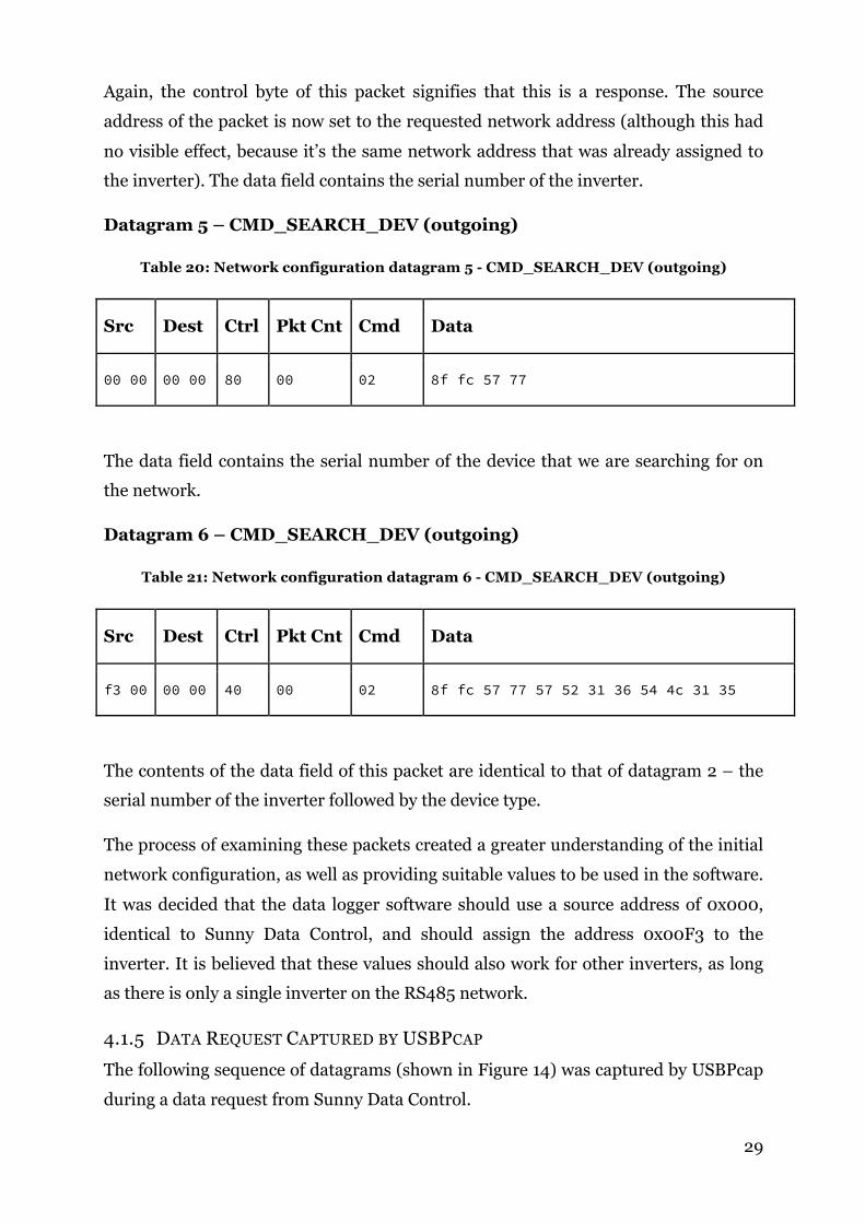
Again, the control byte of this packet signifies that this is a response. The source
address of the packet is now set to the requested network address (although this had
no visible effect, because it’s the same network address that was already assigned to
the inverter). The data field contains the serial number of the inverter.
Datagram 5 – CMD_SEARCH_DEV (outgoing)
Table 20: Network configuration datagram 5 - CMD_SEARCH_DEV (outgoing)
Src Dest Ctrl Pkt Cnt Cmd Data
00 00 00 00 80 00 02 8f fc 57 77
The data field contains the serial number of the device that we are searching for on
the network.
Datagram 6 – CMD_SEARCH_DEV (outgoing)
Table 21: Network configuration datagram 6 - CMD_SEARCH_DEV (outgoing)
Src Dest Ctrl Pkt Cnt Cmd Data
f3 00 00 00 40 00 02 8f fc 57 77 57 52 31 36 54 4c 31 35
The contents of the data field of this packet are identical to that of datagram 2 – the
serial number of the inverter followed by the device type.
The process of examining these packets created a greater understanding of the initial
network configuration, as well as providing suitable values to be used in the software.
It was decided that the data logger software should use a source address of 0x000,
identical to Sunny Data Control, and should assign the address 0x00F3 to the
inverter. It is believed that these values should also work for other inverters, as long
as there is only a single inverter on the RS485 network.
4.1.5 DATA REQUEST CAPTURED BY USBPCAP
The following sequence of datagrams (shown in Figure 14) was captured by USBPcap
during a data request from Sunny Data Control.

! 30
1. CMD_SYN_ONLINE (OUT)
7e:ff:03:40:41:00:00:00:00:80:00:0a:22:24:49:54:8d:7d:5d:7e
2. CMD_GET_DATA (OUT)
7e:ff:03:40:41:00:00:f3:00:00:00:0b:0f:09:00:d5:d5:7e
3. CMD_GET_DATA (IN)
7e:ff:03:40:41:f3:00:00:00:40:00:0b:0f:09:00:01:00:22:24:49:54:01:00:00:00:
d2:00:d1:00:e6:04:0a:00:5b:09:8a:13:2c:01:b8:0b:4c:09:8a:13:e2:01:08:06:e3:
02:57:01:7f:01:04:00:04:00:d3:f8:1e:00:3e:d6:cb:00:aa:27:f1:00:6e:0e:00:00:
f0:00:00:00:8f:fc:57:77:07:00:dd:62:7e
Figure 14: Data request packets captured by USBPcap
Datagram 1 – CMD_SYN_ONLINE (outgoing)
Table 22: Data request datagram 1 - CMD_SYN_ONLINE (outgoing)
Src Dest Ctrl Pkt Cnt Cmd Data
00 00 00 00 80 00 0a 22 24 49 54
This command is sent as a broadcast (Ctrl = 0x80) and the 4 bytes of the data field
contains the current Epoch time in little-endian format. In this case, the time is
0x54492422, or 2014-10-23 15:52:02.
Datagram 2 – CMD_GET_DATA (outgoing)
Table 23: Data request datagram 2 - CMD_GET_DATA (outgoing)
Src Dest Ctrl Pkt Cnt Cmd Data
00 00 f3 00 00 00 0b 0f 09 00
This command is sent directly from the data logger (address 0x0000) to the inverter
(address = 0x00f3). The data field contains the two byte transfer mask followed by
the index of the channel that was requested (see Section 3.2.2). A channel index of
! 31
0x00 means that all channels that match the transfer mask will be returned (see
Section 3.2.2).
Datagram 3 – CMD_GET_DATA (incoming)
Table 24: Data request datagram 3 - CMD_GET_DATA (incoming)
Src Dest Ctrl Pkt Cnt Cmd Data
f3 00 00 00 40 00 0b 0f 09 00 01 00 22 24 49 54 01 00 00 00
d2 00 d1 00 e6 04 0a 00 5b 09 8a 13 2c
01 b8 0b 4c 09 8a 13 e2 01 08 06 e3 02
57 01 7f 01 04 00 04 00 d3 f8 1e 00 3e
d6 cb 00 aa 27 f1 00 6e 0e 00 00 f0 00
00 00 8f fc 57 77 07 00
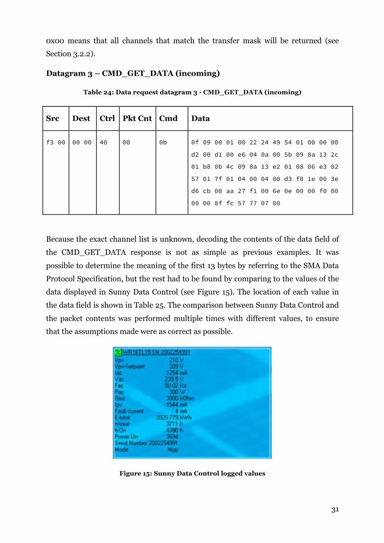
Because the exact channel list is unknown, decoding the contents of the data field of
the CMD_GET_DATA response is not as simple as previous examples. It was
possible to determine the meaning of the first 13 bytes by referring to the SMA Data
Protocol Specification, but the rest had to be found by comparing to the values of the
data displayed in Sunny Data Control (see Figure 15). The location of each value in
the data field is shown in Table 25. The comparison between Sunny Data Control and
the packet contents was performed multiple times with different values, to ensure
that the assumptions made were as correct as possible.
Figure 15: Sunny Data Control logged values

! 32
Table 25: Assumed data request field values and byte positions by comparing datagrams to Sunny Data Control
Field Name Notes Value (converted)
Hexidecimal (little endian)
Byte numbers
Transfer Mask --- 09 0f 0 - 1
Channel Index --- 00 2
Number of records --- 01 00 3 - 4
Timestamp --- 22 24 49 54 5 - 8
Time basis --- 01 00 00 00 9 – 12
Vpv (V) 210 d2 00 13 - 14
Vpv-Setpoint (V) 209 d1 00 15 - 16
Iac (mA) 1254 E6 04 17 - 18
? Unknown 10 0a 00 19 - 20
Vac (V) Scale by 10 2395 5b 09 21 - 22
Fac (Hz) Scale by 100 5002 8a 13 23 – 24
Pac (W) 300 2c 01 25 - 26
Riso (kΩ) 3000 b8 0b 27 - 28
? Unknown 2380 4c 09 29 - 30
Fac (Hz) Scale by 100,
repeated
5002 8a 13 31 - 32
? Unknown 482 e2 01 33 - 34
Ipv (mA) 1544 08 06 35 - 36
? Unknown e3 02 57 01 7f 01 37 - 42
Fault Current (mA) 4 04 00 43 – 44
Fault Current (mA) Repeated 4 04 00 45 – 46
E-total (kWh) Transferred as
Wh
2029779 D3 f8 1e 00 47 - 50
h-total (hours) Transferred as
seconds
13358654 (s) 3e d6 cb 00 51 - 54
h-On (hours) Transferred in
seconds
15804330 (s) aa 27 f1 00 55 - 58
Power On 3694 6e 0e 00 00 59 - 62
? Unkown 240 f0 00 00 00 63 - 66
Serial Number 2002254991 8f fc 57 77 67 - 70
Unknown Unknown 7 07 00 71 - 72
Some values are transferred in a format different to that displayed in Sunny Data
Control; for example, h-total appears in Sunny Data Control as 3711 hours, but is
transferred as 13358654 seconds (equivalent to 3710.7 hours). Additionally, some

! 33
fields seem to appear twice, such as Fac and Fault current. There are also some
streams of bytes that appear in the data but do not seem to be associated with any
values in Sunny Data Control. To fully determine their function would require
parsing the channel list of the inverter. This was not implemented in this data logger
due to the limited SRAM of the Arduino – it has only 2KB of SRAM, while the
channel list is approximately 8KB.
The data field that is currently recorded by the data logger is E-total. This is a
measurement of the total energy generated by the data logger since it was installed.
The data that is required for the solar forecasting project is the average power output
over 5 minute intervals, which can be calculated from the total energy at two
moments in time, as well as the timestamps for those times. This is described in
Section 4.6.
4.1.6 ARDUINO SERIAL ECHO
As mentioned previously in Section 4.1.3, the ‘magic’ bytes did not appear in any data
captures made by USBPcap. This proved problematic after the SMA protocols had
been implemented in Arduino code, prior to having any knowledge of the ‘magic’
bytes. During testing the communication with inverter, the inverter was not
responding to any commands because the Arduino was not sending the ‘magic’ bytes.
To investigate why the inverter was not responding, a small program was written for
the Arduino that would echo any bytes that it received via the RS485 connection to an
open serial monitor on a connected PC. The RS485 shield on the Arduino was
connected to a PC using the USB-to-RS485 cable, and the USB port on the Arduino
was also connected to the PC to allow the RS485 communications to be monitored via
the serial monitor in the Arduino IDE. The network configuration procedure in
Sunny Data Control was then started, with the outgoing packets being sent to the
Arduino. The ‘magic’ bytes were observed in the Arduino IDE serial monitor during
this procedure.
4.2 IMPLEMENTATION OF PROTOCOLS AND RS485 COMMUNICATION
4.2.1 DATA STRUCTURES
Two data structure types were created while implementing the SMA protocols –
SMADataPacket and SMADevice. These represent an SMA Data datagram and an
SMA device respectively. The SMADataPacket data structure contains all of the
! 34
fields and values required to construct an SMA Data telegram, and SMADevice
structure contains the serial number, address and device type of an inverter. Both of
these data structures were defined in the header file sma_defs.h, which can be
found in Appendix A.8.
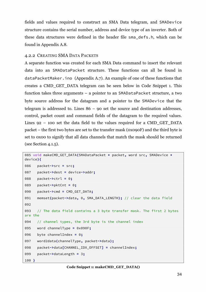
4.2.2 CREATING SMA DATA PACKETS
A separate function was created for each SMA Data command to insert the relevant
data into an SMADataPacket structure. These functions can all be found in
dataPacketMaker.ino (Appendix A.7). An example of one of these functions that
creates a CMD_GET_DATA telegram can be seen below in Code Snippet 1. This
function takes three arguments – a pointer to an SMADataPacket structure, a two
byte source address for the datagram and a pointer to the SMADevice that the
telegram is addressed to. Lines 86 – 90 set the source and destination addresses,
control, packet count and command fields of the datagram to the required values.
Lines 92 – 100 set the data field to the values required for a CMD_GET_DATA
packet – the first two bytes are set to the transfer mask (0x090F) and the third byte is
set to 0x00 to signify that all data channels that match the mask should be returned
(see Section 4.1.5).
085 void makeCMD_GET_DATA(SMADataPacket * packet, word src, SMADevice * device){
086 packet->src = src;
087 packet->dest = device->addr;
088 packet->ctrl = 0;
089 packet->pktCnt = 0;
090 packet->cmd = CMD_GET_DATA;
091 memset(packet->data, 0, SMA_DATA_LENGTH); // clear the data field
092
093 // The data field contains a 3 byte transfer mask. The first 2 bytes are the
094 // channel types, the 3rd byte is the channel index
095 word channelType = 0x090F;
096 byte channelIndex = 0;
097 word2data(channelType, packet->data);
098 packet->data[CHANNEL_IDX_OFFSET] = channelIndex;
099 packet->dataLength = 3;
100 }
Code Snippet 1: makeCMD_GET_DATA()

! 35
4.2.3 CALCULATING CHECKSUMS
YASDI (SMA’s open-source implementation of the SMA protocols) provides code for
calculating the SMA Net checksums using a lookup table. Initially, this code was
directly adapted for use in the data logger without any modifications. However, due
to the large memory requirement for the lookup table (512 bytes) and low RAM
capacity of the Arduino (2 kilobytes), the lookup table had to be moved into the
EEPROM of the Arduino. A small utility program was created to write the lookup
table into the EEPROM. This only needs to be run once, prior to the installation of
the data logger software. This utility program can be found in Appendix A.1.
Calculating the checksum itself is done by calling the function calculateFCS().
This function is originally from YASDI; however, it has been slightly modified to read
the lookup table from the EEPROM of the Arduino rather than from an array stored
in RAM. There are two small utility functions to facilitate this – fcstab() and
EEPROMreadWord(). fcstab() multiplies the original index of the correct entry in
the lookup table by two to obtain the correct memory address for the respective entry
in the EEPROM. It then calls EEPROMreadWord(), which reads and returns the 2
byte word from the EEPROM at the given memory address.
4.2.4 SENDING DATA TO THE INVERTER
There are three functions implemented for sending data over the RS485 Serial
Connection – sendByte(), sendWord(), and sendSMADataPacket. The prototypes of
these functions are shown in Code Snippet 2, with the full functions found in
Appendix A.6.
void sendSMADataPacket(SMADataPacket * packet, HardwareSerial &serial);
void sendWord(word input, HardwareSerial &serial);
void sendByte(byte input, HardwareSerial &serial);
Code Snippet 2: Function prototypes for writing to the RS485 serial connection
sendByte() writes a single byte to the Serial, and also implements the code to
handle escape characters (see section 3.1.2); if the input byte needs to be escaped, this
function will first write the escape character 0x7D to the UART buffer, and then write
the escaped byte (the input byte XOR 0x20).
sendWord() writes a 2 byte word to the UART byte–by-byte using the sendByte()
function, but first converts it into little-endian format.

! 36
sendSMADataPacket() writes an SMADataPacket structure encapsulated by an
SMA Net frame to the RS485 serial connection, including magic bytes (Section 3.1.4)
and checksum calculation (Section 3.1.3 and Section 4.2.3). Pin 2 of the Arduino must
be set HIGH to enable the RS485 transmission; Code Snippet 3 ensures that it
remains high until the UART buffer is empty. This is a method outlined by Nick
Gammon in a 2011 tutorial uploaded to his website (Gammon 2011). UCSR0A is a
register on the ATMega328 chip that contains status data. UDRE0 is a bit in this
register that is set HIGH by the ATMega328 when the UART buffer is not empty.
TXC0 is another bit in this register that is set HIGH when all data has been
transmitted.
088 while (!(UCSR0A & (1 << UDRE0))) UCSR0A |= 1 << TXC0; // mark transmission not complete while the transmit buffer is not empty
089
090 while (!(UCSR0A & (1 << TXC0))); // Wait for the transmission to complete
091
092 //disable rs485 transmission
093 digitalWrite(RS485_ENABLE, LOW);
Code Snippet 3: Waiting for the transmit buffer of the UART to empty
4.2.5 RECEIVING DATA FROM THE INVERTER
The function rs485Receive() listens on the HardwareSerial for the start byte (0x7E)
of an SMA Net frame. If it does not receive a start byte within a timeout period, the
function returns -1, signifying an error. After receiving the start byte, the function will
then read data from the serial connection into a buffer until it receives the stop byte
(0x7E). The data is then verified by calculating the checksum and comparing it to the
received checksum (the last 2 bytes in the buffer). An error is returned if the
checksum is incorrect. After verification of the checksum, the buffer is parsed into an
SMADataPacket structure using the function parseSMADataPacket(). Full function
definitions can be found in Appendix A.6.
int rs485Receive(SMADataPacket * packet, HardwareSerial &serial, unsigned int timeout);
void parseSMADataPacket(byte * buffer, int len, SMADataPacket * packet);
Code Snippet 4: Function prototypes for receiving and parsing SMA data

! 37
4.2.6 PARSING RECEIVED DATA
After the data has been parsed into an SMADataPacket structure, the data field of
that packet can be parsed. There are various functions for doing this, depending on
the SMA Data command of the packet (see Appendix A.9). An example function is
shown in Code Snippet 5. The function first checks that the command and control
fields contain the correct data, and that the length of the data in the data field is
correct for the SMA Data command (in this case it’s CMD_CFG_NETADR). If these
fields are correct, the four bytes of data in the data field should contain the serial
number of the device. This data can be copied directly into the serial field of the
inputted device using memcpy(), because SMA Data and Arduino both use little-
endian memory addressing.
60 int parseCMD_CFG_NETADR(SMADataPacket * packet, SMADevice * device) {
061 //Check that the correct cmd type was sent
062 if (packet->cmd != CMD_CFG_NETADR) return 0;
063
064 // Check that the response flag is set
065 if (!(packet->ctrl & SMADATA_FLAG_RESPONSE)) return 0;
066
067 // The user data section of the packet should be 4 bytes long
068 if (packet->dataLength != 4) return 0;
069
070 // Copy the serial number. Arduino is little endian so there shouldn't be any
071 // problems directly copying it
072 memcpy(&device->serial, packet->data, 4*sizeof(byte));
073
074 //set the address of the device to the source of the message
075 device->addr = packet->src;
076
077 return 1;
078 }
Code Snippet 5: Parsing the data field of a CMD_CFG_NETADR response packet
4.3 COMMUNICATING WITH AND CONTROLLING THE GPRS/GSM SHIELD
The primary purpose of the GPRS/GSM shield in the data logger is to provide
functionality for uploading data to the server via FTP over the GPRS network. There
is also a secondary purpose – the shield contains a real time clock (RTC) that is

! 38
updated by timestamps received from the mobile network. The RTC is used to update
and synchronise the time of the Arduino’s internal clock.
The code used to implement these functions is a modified version of an Arduino
program written by Alejandro Gallego in 2013 (Gallego 2013). The modifications
include changing the original communication over the UART on pins 0 and 1 to the
use of a SoftwareSerial on pins 8 and 9 (necessary because of the modifications made
to the hardware; see Section 2.3), addition of a function to set the Arduino’s clock to
the time retrieved, and moving the strings for the AT Commands that were originally
stored in the SRAM into flash memory (due to limited SRAM). This modified code
can be found in Appendix A.4.
4.3.1 AT COMMANDS
Communication with the GPRS/GSM shield is done through the use of AT
Commands. A full list and description of the AT Commands compatible with the
DFRobot GPS/GPRS/GSM shield can be found in the SIMCOM (2011) SIM908
Command Manual; only those relevant to the data logger project will be listed and
described in Table 26. Unless specified otherwise, the expected response from the
GPRS/GSM shield if the command was successful is “OK”.
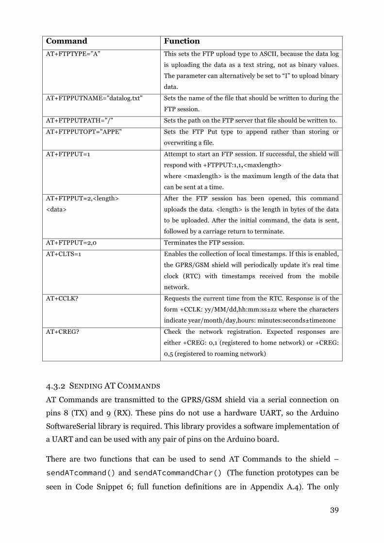
Table 26: AT Commands used by the data logger
Command Function AT The GPRS/GSM shield will respond with “OK” if it is
powered on and ready to receive commands.
AT+SAPBR=3,1,<parameter>,<value> Sets the bearer settings for the data connection (bearer 1 in
this case). The parameters that need to be set are the
connection type (CONTYPE), access point name (APN),
username (USER) and password (PASSWORD).
AT+SAPBR=1,1 Connects to the bearer (bearer 1) that was configured with
the previous AT+COMMAND.
AT+FTPCID=1
Sets the FTP bearer to 1. This is the bearer that was
configured with the previous 2 commands.
AT+FTPPW=<ftp password> Sets the FTP password.
AT+FTPUN=<ftp username> Sets the FTP username.
AT+FTPSERV=<server address> Set the URL or IP address of the server that the data is being
uploaded to.
AT+FTPPORT=21 Set the FTP port of the server. In this case it is port 21.
! 39
Command Function AT+FTPTYPE=”A” This sets the FTP upload type to ASCII, because the data log
is uploading the data as a text string, not as binary values.
The parameter can alternatively be set to “I” to upload binary
data.
AT+FTPPUTNAME="datalog.txt" Sets the name of the file that should be written to during the
FTP session.
AT+FTPPUTPATH="/" Sets the path on the FTP server that file should be written to.
AT+FTPPUTOPT="APPE" Sets the FTP Put type to append rather than storing or
overwriting a file.
AT+FTPPUT=1 Attempt to start an FTP session. If successful, the shield will
respond with +FTPPUT:1,1,<maxlength> where <maxlength> is the maximum length of the data that
can be sent at a time.
AT+FTPPUT=2,<length>
<data>
After the FTP session has been opened, this command
uploads the data. <length> is the length in bytes of the data
to be uploaded. After the initial command, the data is sent,
followed by a carriage return to terminate.
AT+FTPPUT=2,0 Terminates the FTP session.
AT+CLTS=1 Enables the collection of local timestamps. If this is enabled,
the GPRS/GSM shield will periodically update it’s real time
clock (RTC) with timestamps received from the mobile
network.
AT+CCLK? Requests the current time from the RTC. Response is of the
form +CCLK: yy/MM/dd,hh:mm:ss±zz where the characters
indicate year/month/day,hours: minutes:seconds±timezone
AT+CREG? Check the network registration. Expected responses are
either +CREG: 0,1 (registered to home network) or +CREG:
0,5 (registered to roaming network)
4.3.2 SENDING AT COMMANDS
AT Commands are transmitted to the GPRS/GSM shield via a serial connection on
pins 8 (TX) and 9 (RX). These pins do not use a hardware UART, so the Arduino
SoftwareSerial library is required. This library provides a software implementation of
a UART and can be used with any pair of pins on the Arduino board.
There are two functions that can be used to send AT Commands to the shield –
sendATcommand() and sendATcommandChar() (The function prototypes can be
seen in Code Snippet 6; full function definitions are in Appendix A.4). The only

! 40
difference between the two is that sendATcommand()sends command strings that
are stored in flash memory, while sendATcommandChar() sends commands that
are stored in SRAM. It was necessary to include both because although the majority
of the AT Commands are static and stored in the flash memory, there is one AT
command that is constructed dynamically in the code.
int8_t sendATcommand(const __FlashStringHelper* ATcommand, char* expected_answer, unsigned int timeout);
int8_t sendATcommandChar(char* ATcommand, char* expected_answer, unsigned int timeout);
Code Snippet 6: Function prototypes for sending AT Commands
These two functions will write the ATcommand to the SoftwareSerial on pins 8
and 9, and then wait until the GPRS/GSM shield responds with expected_answer;
however, if the shield takes more than the parameter timeout (in seconds) to
respond, the function will return 0, meaning the command failed. The function will
return 1 if the command was successful (i.e., the Arduino received the correct answer
back from the shield).
4.3.3 INITIALISING THE GPRS/GSM SHIELD
DFRobot outlines the steps required to initialise the GPRS/GSM Shield on their wiki
page for the shield. The steps specifically used for this project will be summarised
here. The UART select switch on the right hand side of the shield should be in the
middle position because we will be setting the UART in the software, not hardware.
Switch S1 should be set to “Comm” and switch S2 should be set to “Arduino”.
During the initialisation in software, pins 3, 4 and 5 must be set as digital outputs.
Pin 3 is set to LOW to enable GPRS/GSM; pin 4 is set to HIGH to disable GPS.
During this initialisation process, pin 5 must be set HIGH for 1.5 seconds and then
set back to LOW to set the GSM timing. After this is done, the command “AT” is sent
to the shield to check that it is online. If the shield is powered on correctly it will
respond with “OK” and the “STAT” LED on the right hand side of the shield will be lit
up. If it is off, the reset button on the shield should be pressed. Finally, timestamp
updates are enabled by sending the command “AT+CLTS=1”. This initialisation
process is performed by the function gsmPowerOn(), found in Appendix A.4.

! 41
4.3.4 CONFIGURING BEARER AND FTP SETTINGS
Before transmitting data, first the bearer settings must be set. The required
information is the access point name (APN), username and password. This
information can be obtained from the mobile network provider. To set the connection
type to GPRS and set these parameters, the following sequence of commands is used,
with the parameters enclosed in angle brackets (<>) replaced with the respective
details received from the provider, surrounded by quotation marks:
AT+SAPBR=3,1,"CONTYPE","GPRS"
AT+SAPBR=3,1,"APN",<APN>
AT+SAPBR=3,1,"USER",<USERNAME>
AT+SAPBR=3,1,"PWD",<PASSWORD>
The data logger then connects to this bearer with the command A+SAPBR=1,1.
The FTP settings can be configured using the FTP AT Commands found in Table 26.
In the software for the data logger, the bearer and FTP configuration is performed by
the function configureFTP(), found in gsm.ino (Appendix A.4)
4.3.5 OPENING AN FTP SESSION
After correctly configuring the FTP settings using the steps described in Section 4.3.4,
the FTP session can be opened. To request an FTP session to be started, the
command AT+FTPPUT=1 is sent to the GPRS/GSM shield. The shield will reply with
+FTPPUT:1,1,<maxlength>, where <maxlength> is the maximum length of the data
that can be sent at a time.
Data can then be uploaded using the command AT+FTPPUT=2,<length>, where
<length> is the number of bytes to be uploaded. The maximum value of <length>
is the <maxlength> that was returned from the AT+FTPPUT=1 command. This is
followed by the data that should be uploaded, terminated with a carriage return (new
line). The FTP session can then be terminated with the command AT+FTPPUT=2,0.
This sequence of commands is performed by the function uploadFTP(), found in
gsm.ino(Appendix A.4). The function prototype can be seen below in Code Snippet
7. The “data” parameter is a pointer to the character string that should be
transferred, and the “length” parameter is the length of this string.

! 42
void uploadFTP(char * data, int length);
Code Snippet 7: uploadFTP() function prototype
4.4 LOGGING DATA
The requirements of the data logger stated that data should be stored locally, as well
as transferred to the offsite server via FTP. The local storage is performed using the
SD Card, and the FTP transfers are performed using the GPRS shield.
4.4.1 SD CARD
The SD card module used for this project is fully compatible with the Arduino SD
Card library. The code for saving the data to the SD card is shown in Code Snippet 8,
which is extracted from sma_data_logger.ino (Appendix A.2). This code first
constructs a text string containing the timestamp and the total energy, separated by a
comma. It then attempts to open the file “datalog.txt” on the SD and write to it. The
file must always be closed after writing, because the Arduino SD Card libraries only
allow for one file to be open at a time.
216 //Build data string from the timestamp and measured energy
217 String dataString = "";
218 dataString += String(currentTime);
219 dataString += ",";
220 dataString += eTotal;
221
222 // Write the data to the SD card
223 File dataFile = SD.open("datalog.txt", FILE_WRITE);
224
225 Serial.println(dataString); //print to serial monitor just for checking
226
227 // if the file is available, write to it:
228 if (dataFile) {
229 dataFile.println(dataString);
230 dataFile.close();
231 // print to the serial port too:
232 }
Code Snippet 8: Writing data to the SD card

! 43
4.4.2 FTP UPLOADS
After saving the data to the SD Card, the data logger then attempts to upload the data
to the server, using the uploadFTP() function described in Section 4.3.5. An
example of this is shown in Code Snippet 9. The same data string that was created for
saving to the SD Card is used; however, it must first be converted from a String object
to a character array, because the uploadFTP() function does not support the
Arduino String object. This is something that could potentially be updated in future
versions of the software.
234 // Upload data via FTP
235 dataString += "\n"; //we need to add the new line character
236 char buffer[dataString.length() + 1]; //we add 1 to ensure that the newline character is included
237
238 dataString.toCharArray(buffer, dataString.length()+1);
239 uploadFTP(buffer, dataString.length());
Code Snippet 9: Uploading data via FTP
4.5 COMPLETE SOFTWARE
The main program makes use of the various functions described in this chapter to
implement the data logger. It can be found in the file sma_data_logger.ino (Appendix
A.2). The program contains two main functions, setup() and loop(). This is
standard for all Arduino programs – the setup() function is called when the device
is powered on or reset, and the loop() function is called from within an infinite
loop. During the compilation process the Arduino IDE correctly implements this in C;
the process is not visible to the user.
During setup(), the data logger initialises the SD Card, checks that the GPRS/GSM
shield is powered on and responding to AT Commands, configures the FTP setting,
checks GPRS/GSM network registration, synchronises the Arduino’s internal clock
with the GPRS/GSM shield, and configures the SMA Network according to the
sequence of commands described in Table 12.
The loop() function compares the current time to the timestamp of the most recent
data log. If this is more than 5 minutes, the data logger will request data from the
inverter using the sequence of commands listed in Table 13. This data will then be
saved to the SD card and uploaded to the FTP server. The Arduino’s time is then

! 44
resynchronised with the RTC of the GPRS/GSM shield to prevent clock drift or time
changes (e.g. daylight savings time).
To install the software on the data logger, the first step is to put the source file
fcs_eeprom_setup.ino into a folder called fcs_eeprom_setup. This is then
opened in the Arduino IDE and compiled and flashed to the Arduino. This program
will copy the lookup table for calculating the SMA Net checksums into the EEPROM
of the Arduino. This only needs to be done once. Next, all the other source files
should be put into a folder named sma_data_logger. With the Arduino IDE, open
the source file sma_data_logger.ino and compile and flash it to the data logger.
The data logger can then be connected to the inverter via the RS485 interface and
powered on.
4.6 CALCULATING AVERAGE POWER FROM DATA
The data that is logged at each five minute interval by the data logger is a timestamp
(Epoch time) and the total energy generated by the inverter for all time, in Watt
hours. However, the data required for the solar forecasting project is the average
power generated over the five minute interval. This can be calculated using Equation
1, where t1, t2 are two times with t2 > t1 and e1, e2 are the total energy measurements at
these timestamps, respectively.
Equation 1: Formula for calculating average power from timestamps and total energy
!!!,!! =3600(!! − !!)
!! − !!
The advantage of logging the data in this format is that if a data upload fails, it is still
possible to calculate the average power generated, although it will be over a greater
time period, lowering the resolution of the data.

! 45
Chapter 5 RESULTS
The data logger was connected to the SMA 1600TL on the roof of the Engineering
Building (building 32) at the Australian National University from the 18th of October
to the 23rd of October 2014. It was able to successfully log data to the on-board SD
card without errors for the full period of time that it was installed. There was one
failed FTP upload on the 19th of October at 11:04 AM; however, all uploads before and
after this were successful up until 1:49 PM on the 21st of October. From this point
onwards there were no further FTP uploads, and the data logger was disconnected at
2:59 PM on the 23rd of October. At this point in time, there was no error logging
implements for the GPRS/GSM shield, and therefore the exact reason for the FTP
uploads failing is unknown.
5.1 EXAMPLE DATA
The raw data from the period from 19th to 20th of October can be found in Appendix
A.11. This data was obtained from the file that the data logger was appending to on
the FTP server used for the project. By using the method for calculating the average
power from the data as described in Section 4.6, it was possible to plot the average
power and cumulative energy generated for these two days. These plots can be seen in
Figure 16: Average power and cumulative energy generated 19th of October 2014

! 46
Figure 17: Average power and cumulative energy generated 20th of October 2014

! 47
Chapter 6 CONCLUSIONS AND FUTURE WORK
6.1.1 CONCLUSION
Through the use of inexpensive Arduino hardware it was possible to develop a
prototype data logger that is capable of interfacing with an SMA 1600TL inverter over
an RS485 interface, logging the retrieved data locally onto an attached SD card, and
uploading this data to an offsite server wirelessly via a GPRS data connection. The
total cost for this hardware is AUD$193.06, 38% of the minimum cost of the Sunny
WebBox data logger manufactured by SMA. It is expected that custom made Arduino
boards and bulk purchasing will lower this price even further, meaning the low cost
goal of this project can be considered successful.
The data logger is functional and meets the required specifications that it should be
inexpensive and have the capability of uploading logged data to an offsite server over
a GPRS connection; however, there are still some modifications and improvements
that could be made to the hardware before it is deployed. Suggestions for the
improvements have been outlined in the following section.
6.1.2 FUTURE WORK
Further error checking and logging should be implemented to make the data logger
more robust and less susceptible to failures. Currently, if a failure occurs it would
require someone to go to the location of the data logger and restart it manually.
Additionally, there is no logging of errors to the SD Card. It could be useful to
implement a method of logging the serial output of the data logger to the SD Card for
debugging purposes, in the situations when errors occur while the serial output of the
data logger is not being monitored.
Although the data logger is functional and works the SMA 1600TL inverter, it was
initially envisioned that it would be a plug-and-play data logger that could work with
any SMA inverter. Because all of SMA’s inverters use the same protocols, the code
should only need small modifications to fit other inverters – specifically, the byte
offset of the “total energy” value in the CMD_GET_DATA response would have to be
determined for each model. By implementing a method of properly downloading and
parsing the channel list, it should be possible for the data logger to automatically
search for the index of the correct channel in the channel list. However, there are
some obstacles in the way of this, specifically the limited SRAM of the Arduino. It

! 48
might be possible to overcome this by making use of the additional memory in the SD
Card.
In addition to working with SMA inverters, it should be possible to modify the code to
work with inverters manufactured by another company. This would involve
identifying and implementing the protocols used by these inverters and replacing the
SMA specific code with new code that implements these protocols.
To conclude, a functioning prototype of a data logger was successfully developed with
the capability of communicating with an SMA 1600TL inverter and uploading data to
an offsite server. Although there are still some issues to resolve before it can be
deployed, it should still be a valuable starting point for future development and be of
great use to the solar forecasting project.

! 49
REFERENCES
Arduino 2014, Arduino Uno, Arduino SA, accessed 25 October 2014. http://arduino.cc/en/Main/arduinoBoardUno
Gallego, A 2013. Geolocation Tracker (GPRS + GPS) with SIM908 over Arduino and Raspberry Pi, Libelium Comunicaciones Distribuidas S.L., accessed 17 October 2014. http://www.cooking-hacks.com/documentation/tutorials/geolocation-tracker-gprs-gps-geoposition-sim908-arduino-raspberry-pi
Gammon, N 2011, RS485 Communications, Gammon Software Solutions. Accessed 29 October 2014. http://www.gammon.com.au/forum/?id=11428
Liu, L 2013, ‘3G Enabled Data Logger for Monitoring Distributed Solar Energy Generation.’ undergraduate thesis, Australian National University. https://www.dropbox.com/s/bx4ad0yhfvamxrd/ENGN4200_Thesis_u5090648_Leo_Liu.pdf
Sayeef, S, Heslop, S, Cornforth, D, Moore, T, Percy, S, Ward, JK, Berry, A & Rowe, D 2012, ‘Solar Intermittency: Australia’s clean energy challenge’, CSIRO, accessed 10 April 2014. http://www.csiro.au/Organisation-Structure/Flagships/Energy-Flagship/Solar- Intermittency-Report.aspx
SIMCom 2011, SIM908 AT Command Manual, version 1.01, SIMCom Wireless Solutions Ltd, Shanghai, China, accessed 29 October 2014. http://www.dfrobot.com/image/data/TEL0051/3.0/SIM908_AT%20Command%20Manual_V1.01.pdf
SMA 2003, SMA Data Protocol Specification, SMA Solar Technology AG, Niestetal, Germany, accessed 29 October 2014. https://256.com/solar/scripts/smadat-11-ze2203.pdf
SMA 2008, Sunny Data Control, version 3.9.3.4, computer software, SMA Solar Technology AG, Niestetal, Germany, accessed 23 October 2014. http://www.sma-australia.com.au/en_AU/products/software/sunny-data-control.html
SMA 2010, YASDI, version 1.8.1, computer software, SMA Solar Technology AG, Niestetal, Germany, accessed 6 April 2014. http://www.sma-australia.com.au/en_AU/products/software/yasdi.html
SMA 2014, Annual Report 2013, SMA Solar Technology AG, Niestetal, Germany, accessed 24 July 2014. http://www.sma.de/fileadmin/content/global/Investor_Relations/Documents/Finanzb erichte/2013/SMA-2013-en-Gesamt_11-06-2014.pdf
SMA n.d., YASDI Documentation, SMA Solar Technology AG, Niestetal, Germany, accessed 6 April 2014. http://www.sma-australia.com.au/fileadmin/fm- dam/documents/YASDI/YASDI-10NE1106.pdf

! 50
USBPcap 2014, USBPCap, version 1.0.0.7, computer software, USBPcap, accessed 29 October 2014. http://desowin.org/usbpcap/index.html
Williamson, R 2012, Machine-learning-based forecasting of distributed solar energy production, project proposal
Wireshark Foundation 2014, Wireshark, version 1.12.1, computer software, Wireshark Foundation, accessed 27 March 2014. https://www.wireshark.org/download.html

! 51
APPENDIX
A.1 FCS_EEPROM_SETUP.INO
001 /*
002 * SMA Data Logger
003 * Copyright (C) 2014, Christopher Tapper
004 *
005 * This program is free software: you can redistribute it and/or modify
006 * it under the terms of the GNU General Public License as published by
007 * the Free Software Foundation, either version 3 of the License, or
008 * (at your option) any later version.
009 *
010 * This program is distributed in the hope that it will be useful,
011 * but WITHOUT ANY WARRANTY; without even the implied warranty of
012 * MERCHANTABILITY or FITNESS FOR A PARTICULAR PURPOSE. See the
013 * GNU General Public License for more details.
014 *
015 * You should have received a copy of the GNU General Public License
016 * along with this program. If not, see <http://www.gnu.org/licenses/>
017 *
018 */
019 #include <EEPROM.h>
020
021 /**
022 * This program is part of the SMA Data Logger project.
023 * It writes the FCS table to the EEPROM of the Arduino
024 * This should only be done once, before using the data logger
025 * for the first time
026 **/
027 word fcstab[256] = {
028 0x0000, 0x1189, 0x2312, 0x329b, 0x4624, 0x57ad, 0x6536, 0x74bf,
029 0x8c48, 0x9dc1, 0xaf5a, 0xbed3, 0xca6c, 0xdbe5, 0xe97e, 0xf8f7,
030 0x1081, 0x0108, 0x3393, 0x221a, 0x56a5, 0x472c, 0x75b7, 0x643e,
031 0x9cc9, 0x8d40, 0xbfdb, 0xae52, 0xdaed, 0xcb64, 0xf9ff, 0xe876,
032 0x2102, 0x308b, 0x0210, 0x1399, 0x6726, 0x76af, 0x4434, 0x55bd,
033 0xad4a, 0xbcc3, 0x8e58, 0x9fd1, 0xeb6e, 0xfae7, 0xc87c, 0xd9f5,

! 52
034 0x3183, 0x200a, 0x1291, 0x0318, 0x77a7, 0x662e, 0x54b5, 0x453c,
035 0xbdcb, 0xac42, 0x9ed9, 0x8f50, 0xfbef, 0xea66, 0xd8fd, 0xc974,
036 0x4204, 0x538d, 0x6116, 0x709f, 0x0420, 0x15a9, 0x2732, 0x36bb,
037 0xce4c, 0xdfc5, 0xed5e, 0xfcd7, 0x8868, 0x99e1, 0xab7a, 0xbaf3,
038 0x5285, 0x430c, 0x7197, 0x601e, 0x14a1, 0x0528, 0x37b3, 0x263a,
039 0xdecd, 0xcf44, 0xfddf, 0xec56, 0x98e9, 0x8960, 0xbbfb, 0xaa72,
040 0x6306, 0x728f, 0x4014, 0x519d, 0x2522, 0x34ab, 0x0630, 0x17b9,
041 0xef4e, 0xfec7, 0xcc5c, 0xddd5, 0xa96a, 0xb8e3, 0x8a78, 0x9bf1,
042 0x7387, 0x620e, 0x5095, 0x411c, 0x35a3, 0x242a, 0x16b1, 0x0738,
043 0xffcf, 0xee46, 0xdcdd, 0xcd54, 0xb9eb, 0xa862, 0x9af9, 0x8b70,
044 0x8408, 0x9581, 0xa71a, 0xb693, 0xc22c, 0xd3a5, 0xe13e, 0xf0b7,
045 0x0840, 0x19c9, 0x2b52, 0x3adb, 0x4e64, 0x5fed, 0x6d76, 0x7cff,
046 0x9489, 0x8500, 0xb79b, 0xa612, 0xd2ad, 0xc324, 0xf1bf, 0xe036,
047 0x18c1, 0x0948, 0x3bd3, 0x2a5a, 0x5ee5, 0x4f6c, 0x7df7, 0x6c7e,
048 0xa50a, 0xb483, 0x8618, 0x9791, 0xe32e, 0xf2a7, 0xc03c, 0xd1b5,
049 0x2942, 0x38cb, 0x0a50, 0x1bd9, 0x6f66, 0x7eef, 0x4c74, 0x5dfd,
050 0xb58b, 0xa402, 0x9699, 0x8710, 0xf3af, 0xe226, 0xd0bd, 0xc134,
051 0x39c3, 0x284a, 0x1ad1, 0x0b58, 0x7fe7, 0x6e6e, 0x5cf5, 0x4d7c,
052 0xc60c, 0xd785, 0xe51e, 0xf497, 0x8028, 0x91a1, 0xa33a, 0xb2b3,
053 0x4a44, 0x5bcd, 0x6956, 0x78df, 0x0c60, 0x1de9, 0x2f72, 0x3efb,
054 0xd68d, 0xc704, 0xf59f, 0xe416, 0x90a9, 0x8120, 0xb3bb, 0xa232,
055 0x5ac5, 0x4b4c, 0x79d7, 0x685e, 0x1ce1, 0x0d68, 0x3ff3, 0x2e7a,
056 0xe70e, 0xf687, 0xc41c, 0xd595, 0xa12a, 0xb0a3, 0x8238, 0x93b1,
057 0x6b46, 0x7acf, 0x4854, 0x59dd, 0x2d62, 0x3ceb, 0x0e70, 0x1ff9,
058 0xf78f, 0xe606, 0xd49d, 0xc514, 0xb1ab, 0xa022, 0x92b9, 0x8330,
059 0x7bc7, 0x6a4e, 0x58d5, 0x495c, 0x3de3, 0x2c6a, 0x1ef1, 0x0f78
060 };
061
062 void setup(){
063 int i;
064 word test;
065 boolean error = false;
066
067 Serial.begin(1200);
068
069 for (i = 0; i < 256; i++) {
070 EEPROMwriteWord(i*2, fcstab[i]);
071
072 // Check if copied correctly

! 53
073 test = EEPROMreadWord(i*2);
074 if (test != fcstab[i]) {
075 Serial.print("Error at index ");
076 Serial.println(i, DEC);
077 error = true;
078 } else {
079 Serial.println(test, HEX);
080 }
081 }
082
083 if (error) {
084 Serial.println("ERROR: Some data did not copy correctly. Check serial output data.");
085 } else {
086 Serial.println("SUCCESS: Memory copy complete");
087 }
088
089 }
090
091 void loop(){
092
093 }
094
095 word EEPROMwriteWord(int addr, word value) {
096 //stores the word in little endian format starting at addr
097
098 EEPROM.write(addr, (byte) (value & 0x00FF)); //write first byte
099 EEPROM.write(addr+1, (byte) ((value >> 8) & 0xFF)); //write second byte
100 }
101
102 word EEPROMreadWord(int addr) {
103 //reads a little endian word stored in the EEPROM at addr
104 return ((EEPROM.read(addr+1) << 8) + EEPROM.read(addr));
105 }

! 54
A.2 SMA_DATA_LOGGER.INO
001 /*
002 * SMA Data Logger
003 * Copyright (C) 2014, Christopher Tapper
004 *
005 * This program is free software: you can redistribute it and/or modify
006 * it under the terms of the GNU General Public License as published by
007 * the Free Software Foundation, either version 3 of the License, or
008 * (at your option) any later version.
009 *
010 * This program is distributed in the hope that it will be useful,
011 * but WITHOUT ANY WARRANTY; without even the implied warranty of
012 * MERCHANTABILITY or FITNESS FOR A PARTICULAR PURPOSE. See the
013 * GNU General Public License for more details.
014 *
015 * You should have received a copy of the GNU General Public License
016 * along with this program. If not, see <http://www.gnu.org/licenses/>
017 *
018 */
019
020 #include "sma_defs.h"
021 #include "rs485comms.h"
022 #include <Time.h>
023 #include <SoftwareSerial.h>
024 #include <SD.h>
025
026 #define MY_ADDRESS 0x0000 //SMA network address of the data logger
027 #define DEVICE_ADDRESS 0x00F3 //address that we want to assign to the inverter during network configuration
028 #define GSM_BAUD 9600 //baud rate for the GSM shield
029 #define RS485_BAUD 1200 //baud rate for RS485 comms
030 #define LOG_PERIOD 300 //time between data samples in seconds
031
032
033 SMADataPacket packetBuffer; //buffer used for packets to be sent or received
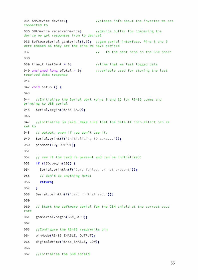
! 55
034 SMADevice device1; //stores info about the inverter we are connected to
035 SMADevice receivedDevice; //device buffer for comparing the device we get responses from to device1
036 SoftwareSerial gsmSerial(8,9); //gsm serial interface. Pins 8 and 9 were chosen as they are the pins we have rewired
037 // to the bent pins on the GSM board
038
039 time_t lastSent = 0; //time that we last logged data
040 unsigned long eTotal = 0; //variable used for storing the last received data response
041
042 void setup () {
043
044 //Initialise the Serial port (pins 0 and 1) for RS485 comms and printing to USB serial
045 Serial.begin(RS485_BAUD);
046
047 //Initialise SD card. Make sure that the default chip select pin is set to
048 // output, even if you don't use it:
049 Serial.print(F("Initializing SD card..."));
050 pinMode(10, OUTPUT);
051
052 // see if the card is present and can be initialized:
053 if (!SD.begin(10)) {
054 Serial.println(F("Card failed, or not present"));
055 // don't do anything more:
056 return;
057 }
058 Serial.println(F("card initialised."));
059
060 // Start the software serial for the GSM shield at the correct baud rate
061 gsmSerial.begin(GSM_BAUD);
062
063 //Configure the RS485 read/write pin
064 pinMode(RS485_ENABLE, OUTPUT);
065 digitalWrite(RS485_ENABLE, LOW);
066
067 //Initialise the GSM shield

! 56
068 Serial.println(F("Initialising GSM..."));
069 gsmPowerOn();
070 delay(5000);
071 Serial.println(F("Connecting to the network..."));
072
073 //Check that network is connected
074 while( (sendATcommand(F("AT+CREG?"), "+CREG: 0,1", 500)
075 || sendATcommand(F("AT+CREG?"), "+CREG: 0,5", 500)) == 0 );
076 configure_FTP();
077
078 // attempt to set the system time, but timeout after 2 seconds
079 setArduinoTime(2000);
080 Serial.println(now(), DEC); //print the current time
081
082 //set the address of this device to the correct one
083 device1.addr = DEVICE_ADDRESS;
084
085 // CONFIGURE SMA NETWORK
086
087 // First we must signal that we are beginning the configuration
088 Serial.println(F("Sending CMD_GET_NET_START"));
089 makeCMD_GET_NET_START(&packetBuffer, MY_ADDRESS);
090 sendSMADataPacket(&packetBuffer, Serial);
091
092 //Wait for a response, but timeout after 5 seconds
093 rs485Receive(&packetBuffer, Serial, 5000);
094
095 //parse the response, perform error checking
096 if (parseCMD_GET_NET_START(&packetBuffer, &device1)) {
097 Serial.print(F("\nReceived CMD_GET_NET_START response from device "));
098 Serial.print(device1.serial);
099 Serial.print(F("\n"));
100 } else {
101 Serial.print(F("Invalid response packet.\n"));
102 return;
103 //TODO: implement what should happen if we receive an invalid packet
104 }
105

! 57
106 delay(30); // This delay is required between sending and receiving messages
107
108 // Now we attempt to set the address of the device
109 Serial.print(F("Setting network address of device "));
110 Serial.print(device1.serial);
111 Serial.print(F(" to "));
112 Serial.print(DEVICE_ADDRESS, HEX);
113 Serial.print(F("\nSending CMD_CFG_NETADR\n"));
114
115 makeCMD_CFG_NET_ADDR(&packetBuffer, MY_ADDRESS, &device1);
116 sendSMADataPacket(&packetBuffer, Serial);
117
118 //Wait for a response, but timeout after 5 seconds
119 rs485Receive(&packetBuffer, Serial, 5000); // timeout after 5 seconds
120
121 //parse the response, perform error checking
122 if (parseCMD_CFG_NETADR(&packetBuffer, &receivedDevice)) {
123
124 Serial.print(F("\nReceived CMD_CFG_NETADR response from device "));
125 Serial.print(receivedDevice.serial);
126 Serial.print(F("\n"));
127
128 if (receivedDevice.addr == DEVICE_ADDRESS) { //check that the address was changed properly
129 device1.addr = DEVICE_ADDRESS;
130 Serial.print(F("Address of device "));
131 Serial.print(device1.serial);
132 Serial.print(F(" succesfully changed to "));
133 Serial.print(device1.addr, HEX);
134 Serial.print(F("\n"));
135 } else {
136 Serial.print(F("Address not set succesfully\n"));
137 Serial.println(device1.addr, HEX);
138 //TODO: implement what should happen if we receive an invalid packet
139 }
140
141 } else {
142 Serial.print(F("Invalid response packet.\n"));

! 58
143 //TODO: implement what should happen if we receive an invalid packet
144
145 }
146
147 delay(30); // This delay is required between sending and receiving messages
148
149 // Send a search device command to confirm that everything is configured correctly
150 Serial.print(F("Searching for device "));
151 Serial.print(device1.serial);
152 Serial.print(F("\nSending CMD_SEARCH_DEV\n"));
153 makeCMD_SEARCH_DEV(&packetBuffer, MY_ADDRESS, &device1);
154 sendSMADataPacket(&packetBuffer, Serial);
155
156 //Wait for a response, but timeout after 5 seconds
157 rs485Receive(&packetBuffer, Serial, 5000); // timeout after 5 seconds
158
159 //parse the response, perform error checking
160 if (parseCMD_SEARCH_DEV(&packetBuffer, &receivedDevice)) {
161
162 Serial.print(F("\nReceived CMD_SEARCH_DEV response from device "));
163 Serial.print(receivedDevice.serial);
164 Serial.print(F("\n"));
165
166 if (receivedDevice.addr == DEVICE_ADDRESS) { //check that the address was changed properly
167 Serial.println(F("Device found successfully"));
168 } else {
169 Serial.print(F("Address not set succesfully.\n"));
170 //TODO: implement what should happen if we receive an invalid packet
171 }
172
173 } else {
174 Serial.print(F("Invalid response packet.\n"));
175 //TODO: implement what should happen if we receive an invalid packet
176 }
177

! 59
178 }
179
180
181 //Main loop of the software starts here
182 void loop () {
183
184 // Check if it is time to log data
185 if (now() - lastSent >= LOG_PERIOD) {
186 time_t currentTime = now();
187 lastSent = now();
188
189 // Sync online data
190 Serial.print(F("Synchronising online data..."));
191 Serial.print(F("\nSending CMD_SYN_ONLINE\n"));
192 makeCMD_SYN_ONLINE(&packetBuffer, MY_ADDRESS, &device1, currentTime);
193 sendSMADataPacket(&packetBuffer, Serial);
194
195 delay(30); //delay required between sending packets
196
197 // Get data
198 Serial.println(F("\nSending CMD_GET_DATA"));
199 makeCMD_GET_DATA(&packetBuffer, MY_ADDRESS, &device1);
200 sendSMADataPacket(&packetBuffer, Serial);
201
202 // try to receive packet, but if we timeout after 5 seconds, resend the CMD_SYN_ONLINE
203 if (rs485Receive(&packetBuffer, Serial, 5000) == -1) {
204 Serial.println(F("\nResponse timed out."));
205 return;
206 }
207
208 //parse to get the energy. Error checking probably doesn't quite work properly here yet.
209 eTotal = parseCMD_GET_DATA(&packetBuffer, currentTime);
210 if (eTotal) {
211 Serial.print(F("\nReceived CMD_GET_GET_DATA response: "));
212 } else {
213 Serial.print(F("Invalid response packet.\n"));
214 }

! 60
215
216 //Build data string from the timestamp and measured energy
217 String dataString = "";
218 dataString += String(currentTime);
219 dataString += ",";
220 dataString += eTotal;
221
222 // Write the data to the SD card
223 File dataFile = SD.open("datalog.txt", FILE_WRITE);
224
225 Serial.println(dataString); //print to serial monitor just for checking
226
227 // if the file is available, write to it:
228 if (dataFile) {
229 dataFile.println(dataString);
230 dataFile.close();
231 // print to the serial port too:
232 }
233
234 // Upload data via FTP
235 dataString += "\n"; //we need to add the new line character
236 char buffer[dataString.length() + 1]; //we add 1 to ensure that the newline character is included
237
238 dataString.toCharArray(buffer, dataString.length()+1);
239 uploadFTP(buffer, dataString.length());
240
241 setArduinoTime(2000); //refresh time in case it has changed
242 }
243
244 }

! 61
A.3 FCS.INO
001 /*
002 /*
003 * This source code has been modified by Christopher Tapper to be used in the
004 * SMA Data Logger project. The original author details and license are below:
005 *
006 * ###############################################################################
007 *
008 *
009 * YASDI - (Y)et (A)nother (S)MA(D)ata (I)mplementation
010 * Copyright(C) 2001-2008 SMA Solar Technology AG
011 *
012 * This library is free software; you can redistribute it and/or
013 * modify it under the terms of the GNU Lesser General Public
014 * License as published by the Free Software Foundation; either
015 * version 2.1 of the License, or (at your option) any later version.
016 *
017 * This library is distributed in the hope that it will be useful,
018 * but WITHOUT ANY WARRANTY; without even the implied warranty of
019 * MERCHANTABILITY or FITNESS FOR A PARTICULAR PURPOSE. See the GNU
020 * Lesser General Public License for more details.
021 *
022 * You should have received a copy of the GNU Lesser General Public
023 * License along with this library in the file COPYING.LIB;
024 * if not, write to the Free Software Foundation, Inc.,
025 * 59 Temple Place - Suite 330, Boston, MA 02111-1307, USA
026 *
027 */
028
029 #include "Arduino.h"
030 #include <EEPROM.h>
031
032 //Calculate the checksum using a byte or array of bytes and the lookup table

! 62
033 word calculateFCS(word fcs, byte * data, word length) {
034
035 while(length--) {
036 fcs = (word)((fcs >> 8) ^ fcstab((fcs ^ *data++) & 0xff));
037 }
038 return (fcs);
039 }
040
041 //Calculate the checksum using a 2 byte Word and the lookup table
042 word fcsWord(word fcs, word data) {
043 byte msb = (byte) ((data >> 8) & 0xFF);
044 byte lsb = (byte) (data & 0xFF);
045
046 fcs = calculateFCS(fcs, &msb, 1);
047 fcs = calculateFCS(fcs, &lsb, 1);
048 return fcs;
049 }
050
051 // The fcstab array (the lookup table) is now stored in the EEPROM. This function
052 // returns the value that would have been stored at index
053 word fcstab(int index) {
054 return EEPROMreadWord(index*2);
055 }
056
057 word EEPROMreadWord(int addr) {
058 //reads a little endian word stored in the EEPROM at addr
059 return ((EEPROM.read(addr+1) << 8) + EEPROM.read(addr));
060 }

! 63
A.4 GSM.INO
001 /*
002 * This source code has been modified by Christopher Tapper to be used in the
003 * SMA Data Logger project. The original author details and license are below:
004 *
005 * ###############################################################################
006 *
007 * Description: This example shows how to upload and download files from a FTP
008 * server. The example configures the module to use FTP funtions, uploads a file
009 * to the FTP server and then downloads the content of the uploaded file and shows
010 * it. This example only shows the AT commands (and the answers of the module)
011 * used to use the FTP funtion and how work the FTP functions. For more
012 * information about the AT commands, refer to the AT command manual.
013 *
014 * Copyright (C) 2013 Libelium Comunicaciones Distribuidas S.L.
015 * http://www.libelium.com
016 *
017 * This program is free software: you can redistribute it and/or modify
018 * it under the terms of the GNU General Public License as published by
019 * the Free Software Foundation, either version 3 of the License, or
020 * (at your option) any later version.
021 *
022 * This program is distributed in the hope that it will be useful,
023 * but WITHOUT ANY WARRANTY; without even the implied warranty of
024 * MERCHANTABILITY or FITNESS FOR A PARTICULAR PURPOSE. See the
025 * GNU General Public License for more details.
026 *
027 * You should have received a copy of the GNU General Public License
028 * along with this program. If not, see <http://www.gnu.org/licenses/>.
029 *

! 64
030 * Version 0.2
031 * Author: Alejandro Gallego
032 *
033 */
034
035 int8_t answer;
036
037 char OK[] = "OK";
038
039 void configure_FTP(){
040
041 sendATcommand(F("AT+SAPBR=3,1,\"CONTYPE\",\"GPRS\""), OK, 2000);
042 sendATcommand(F("AT+SAPBR=3,1,\"APN\",\"yesinternet\""), OK, 2000);
043 sendATcommand(F("AT+SAPBR=3,1,\"USER\",\"\""), OK, 2000);
044 sendATcommand(F("AT+SAPBR=3,1,\"PWD\",\"\""), OK, 2000);
045
046 while (sendATcommand(F("AT+SAPBR=1,1"), OK, 20000) != 1);
047 sendATcommand(F("AT+FTPCID=1"), OK, 2000);
048 sendATcommand(F("AT+FTPTYPE=\"A\""), OK, 2000);
049 sendATcommand(F("AT+FTPSERV=\"FTPSERVERADDRESS\""), OK, 2000);
050 sendATcommand(F("AT+FTPPORT=21"), OK, 2000);
051 sendATcommand(F("AT+FTPUN=\"FTPUSERNAME\""), OK, 2000);
052 sendATcommand(F("AT+FTPPW=\"FTPPASSWORD\""), OK, 2000);
053
054
055 }
056
057 void uploadFTP(char * data, int length){
058 sendATcommand(F("AT+FTPPUTNAME=\"datalog.txt\""), OK, 2000);
059 sendATcommand(F("AT+FTPPUTPATH=\"/\""), OK, 2000);
060 sendATcommand(F("AT+FTPPUTOPT=\"APPE\""), OK, 2000);
061
062 //we need to construct these commands because they can vary depending on the length of the data string
063 String response = "+FTPPUT=2," + String(length);
064 String command = "AT" + response;
065
066 char commandBuffer[command.length()+1]; //have to add 1 for space for the string terminator

! 65
067 char responseBuffer[response.length()+1]; //have to add 1 for space for the string terminator
068
069 command.toCharArray(commandBuffer, command.length()+1); //have to add 1 for space for the string terminator
070 response.toCharArray(responseBuffer, response.length()+1); //have to add 1 for space for the string terminator
071
072 if (sendATcommand(F("AT+FTPPUT=1"), "+FTPPUT:1,1,", 30000) == 1)
073 {
074 if (sendATcommandChar(commandBuffer, responseBuffer, 30000) == 1){
075 Serial.println(sendATcommandChar(data, "+FTPPUT:1,1", 30000),DEC);
076 Serial.println(sendATcommand(F("AT+FTPPUT=2,0"), OK, 30000),DEC);
077 Serial.println(F("FTP upload complete"));
078 } else {
079 Serial.println(F("Error sending FTP data"));
080 }
081 } else {
082 Serial.println(F("Error opening the FTP session"));
083 }
084 }
085
086
087
088
089 void gsmPowerOn(){
090
091 // Configure pins
092 pinMode(3, OUTPUT);
093 pinMode(4, OUTPUT);
094 pinMode(5, OUTPUT);
095
096 //set gsm timing
097 digitalWrite(5, HIGH);
098 delay(1500);
099 digitalWrite(5, LOW);
100
101 digitalWrite(3, LOW); //enable GSM

! 66
102 digitalWrite(4, HIGH); //disable GPS
103 uint8_t answer=0;
104
105 // checks if the module is started
106 answer = sendATcommand(F("AT"), OK, 2000);
107 if (answer == 0)
108 {
109
110 while(answer == 0){ // Send AT every two seconds and wait for the answer
111 answer = sendATcommand(F("AT"), OK, 2000);
112 }
113 }
114 sendATcommand(F("AT+CLTS=1"), OK, 2000); //enable collection of timestamps
115 }
116
117 uint8_t setArduinoTime(unsigned int timeout) {
118 uint8_t x=0, answer=0;
119 char response[100];
120 unsigned long previous;
121
122 memset(response, '\0', 100); // Initialize the string
123
124 delay(100);
125
126 while( gsmSerial.available() > 0) gsmSerial.read(); // Clean the input buffer
127
128 gsmSerial.println(F("AT+CCLK?")); // Send the AT command
129
130 x = 0;
131 previous = millis();
132
133 // this loop waits for the answer
134 do{
135 if(gsmSerial.available() != 0){
136 // if there are data in the UART input buffer, reads it and checks for the asnwer
137 response[x] = gsmSerial.read();

! 67
138 //Serial.print(response[x]);
139 x++;
140 // check if the desired answer is in the response of the module
141 if (strstr(response, "+CCLK: \"") != NULL)
142 {
143 answer = 1;
144 while (gsmSerial.available() < 17); //spin until all characters are in the buffer
145 int xyear = 2000 + (gsmSerial.read()-48)*10 + gsmSerial.read()-48;
146 gsmSerial.read(); //discard this character
147 int xmonth = (gsmSerial.read()-48)*10 + gsmSerial.read()-48;
148 gsmSerial.read(); //discard this character
149 int xday = (gsmSerial.read()-48)*10 + gsmSerial.read()-48;
150 gsmSerial.read(); //discard this character
151 int xhours = (gsmSerial.read()-48)*10 + gsmSerial.read()-48;
152 gsmSerial.read(); //discard this character
153 int xminutes = (gsmSerial.read()-48)*10 + gsmSerial.read()-48;
154 gsmSerial.read(); //discard this character
155 int xseconds = (gsmSerial.read()-48)*10 + gsmSerial.read()-48;
156
157
158 setTime(xhours, xminutes, xseconds, xday, xmonth, xyear);
159
160 }
161 }
162 }
163 // Waits for the asnwer with time out
164 while((answer == 0) && ((millis() - previous) < timeout));
165
166 return answer;
167 }
168
169 int8_t sendATcommand(const __FlashStringHelper* ATcommand, char* expected_answer, unsigned int timeout){

! 68
170
171 uint8_t x=0, answer=0;
172 char response[100];
173 unsigned long previous;
174
175 memset(response, '\0', 100); // Initialize the string
176
177 delay(100);
178
179 while( gsmSerial.available() > 0) gsmSerial.read(); // Clean the input buffer
180
181 gsmSerial.println(ATcommand); // Send the AT command
182 Serial.println(ATcommand);
183
184
185 x = 0;
186 previous = millis();
187
188 // this loop waits for the answer
189 do{
190 if(gsmSerial.available() != 0){
191 // if there are data in the UART input buffer, reads it and checks for the asnwer
192 response[x] = gsmSerial.read();
193 //Serial.print(response[x]);
194 x++;
195 // check if the desired answer is in the response of the module
196 if (strstr(response, expected_answer) != NULL)
197 {
198 answer = 1;
199 }
200 }
201 }
202 // Waits for the asnwer with time out
203 while((answer == 0) && ((millis() - previous) < timeout));
204
205 return answer;
206 }

! 69
207
208 int8_t sendATcommandChar(char* ATcommand, char* expected_answer, unsigned int timeout){
209
210 uint8_t x=0, answer=0;
211 char response[100];
212 unsigned long previous;
213
214 memset(response, '\0', 100); // Initialize the string
215
216 delay(100);
217
218 while( gsmSerial.available() > 0) gsmSerial.read(); // Clean the input buffer
219
220 gsmSerial.println(ATcommand); // Send the AT command
221 Serial.println(ATcommand);
222
223
224 x = 0;
225 previous = millis();
226
227 // this loop waits for the answer
228 do{
229 if(gsmSerial.available() != 0){
230 // if there are data in the UART input buffer, reads it and checks for the asnwer
231 response[x] = gsmSerial.read();
232 //Serial.print(response[x]);
233 x++;
234 // check if the desired answer is in the response of the module
235 if (strstr(response, expected_answer) != NULL)
236 {
237 answer = 1;
238 }
239 }
240 }
241 // Waits for the asnwer with time out
242 while((answer == 0) && ((millis() - previous) < timeout));

! 70
243
244 return answer;
245 }

! 71
A.5 RS485COMMS.H
001 /*
002 * SMA Data Logger
003 * Copyright (C) 2014, Christopher Tapper
004 *
005 * This program is free software: you can redistribute it and/or modify
006 * it under the terms of the GNU General Public License as published by
007 * the Free Software Foundation, either version 3 of the License, or
008 * (at your option) any later version.
009 *
010 * This program is distributed in the hope that it will be useful,
011 * but WITHOUT ANY WARRANTY; without even the implied warranty of
012 * MERCHANTABILITY or FITNESS FOR A PARTICULAR PURPOSE. See the
013 * GNU General Public License for more details.
014 *
015 * You should have received a copy of the GNU General Public License
016 * along with this program. If not, see <http://www.gnu.org/licenses/>
017 *
018 */
019
020 #ifndef RS485COMMS_H_
021 #define RS485COMMS_H_
022
023 #include "Arduino.h"
024 #include "sma_defs.h"
025
026 #define RS485_ENABLE 2
027
028 //Some constants for SMA Net messages
029 #define SMA_NET_START_STOP 0x7E
030 #define SMA_DATA_PROTOCOL_NUMBER 0x4041
031 #define SMA_NET_CTRL 0x03
032 #define SMA_NET_ADDR 0xFF
033
034 //Byte offsets for parsing SMA Net Packets
035 #define SMA_NET_ADDR_BYTE 0

! 72
036 #define SMA_NET_CTRL_BYTE 1
037
038 //The following are the byte offsets used for parsing a packet from the buffer
039 #define SRC_ADDR_LSB 0
040 #define SRC_ADDR_MSB 1
041 #define DEST_ADDR_LSB 2
042 #define DEST_ADDR_MSB 3
043 #define SMA_DATA_CTRL 4
044 #define SMA_DATA_PKT_CNT 5
045 #define SMA_DATA_CMD 6
046 #define SMA_DATA 7
047
048 #define SMA_DATA_HEADER_LENGTH 7
049
050 #define SMA_NET_HEADER_LENGTH 4 //doesn't include the start byte
051 #define SMA_NET_CHECKSUM_LENGTH 2
052 #endif

! 73
A.6 RS485COMMS.INO
001 /*
002 * SMA Data Logger
003 * Copyright (C) 2014, Christopher Tapper
004 *
005 * This program is free software: you can redistribute it and/or modify
006 * it under the terms of the GNU General Public License as published by
007 * the Free Software Foundation, either version 3 of the License, or
008 * (at your option) any later version.
009 *
010 * This program is distributed in the hope that it will be useful,
011 * but WITHOUT ANY WARRANTY; without even the implied warranty of
012 * MERCHANTABILITY or FITNESS FOR A PARTICULAR PURPOSE. See the
013 * GNU General Public License for more details.
014 *
015 * You should have received a copy of the GNU General Public License
016 * along with this program. If not, see <http://www.gnu.org/licenses/>
017 *
018 */
019 #include "rs485comms.h"
020 #include "Arduino.h"
021 #include "sma_defs.h"
022
023 // Encapsulates an SMA Data packet in an SMA Net frame and transmits it
024 // via the RS485 serial.
025 void sendSMADataPacket(SMADataPacket * packet, HardwareSerial &serial) {
026
027 //calculate fcs
028 word fcs = 0xFFFF;
029 byte tempAddr = SMA_NET_ADDR;
030 byte tempCtrl = SMA_NET_CTRL;
031 word tempProtocol = SMA_DATA_PROTOCOL_NUMBER;
032
033 fcs = calculateFCS(fcs, &tempAddr, 1);
034 fcs = calculateFCS(fcs, &tempCtrl, 1);
035 fcs = fcsWord(fcs, tempProtocol);

! 74
036 fcs = fcsWord(fcs, endianSwap16(packet->src));
037 fcs = fcsWord(fcs, endianSwap16(packet->dest));
038 fcs = calculateFCS(fcs, &packet->ctrl, 1);
039 fcs = calculateFCS(fcs, &packet->pktCnt, 1);
040 fcs = calculateFCS(fcs, &packet->cmd, 1);
041 fcs = calculateFCS(fcs, packet->data, packet->dataLength);
042
043 //take compliment of fcs and change to little endian
044 fcs = fcs ^ 0xFFFF;
045 fcs = endianSwap16(fcs);
046
047 // Enable RS485 Transmit
048 digitalWrite(RS485_ENABLE, HIGH);
049
050
051 // send pre sequence
052 sendWord(0xAAAA, serial);
053
054 //write start byte
055 //this doesn't use the 'sendByte' function
056 sendStartStop(serial);
057
058 //write SMA Net Address
059 sendByte(SMA_NET_ADDR, serial);
060
061 //write SMA Net Ctrl Byte
062 sendByte(SMA_NET_CTRL, serial);
063
064 //write Protocol header. This needs to be converted from big endian to little endian
065 sendWord(SMA_DATA_PROTOCOL_NUMBER, serial);
066
067 //write source and destination address of SMA data packet
068 sendWord(endianSwap16(packet->src), serial);
069 sendWord(endianSwap16(packet->dest), serial);
070
071 sendByte(packet->ctrl, serial);
072 sendByte(packet->pktCnt, serial);
073 sendByte(packet->cmd, serial);

! 75
074
075 //write SMA Data contents
076 int i;
077 for (i = 0; i < packet->dataLength; i++) {
078 sendByte(packet->data[i], serial);
079 }
080
081 //write fcs
082 sendWord(fcs, serial);
083
084 //write stop byte
085 sendStartStop(serial);
086 sendWord(0x5555, serial);
087
088 while (!(UCSR0A & (1 << UDRE0))) UCSR0A |= 1 << TXC0; // mark transmission not complete while the transmit buffer is not empty
089
090 while (!(UCSR0A & (1 << TXC0))); // Wait for the transmission to complete
091
092 //disable rs485 transmission
093 digitalWrite(RS485_ENABLE, LOW);
094
095 }
096
097 //reads a packet received over the rs485 interface into a packet buffer
098 int rs485Receive(SMADataPacket * packet, HardwareSerial &serial, unsigned int timeout) {
099
100 boolean packetFinished = false;
101 word bufferedBytes = 0;
102 byte buffer[256];
103 byte inputByte = 0;
104 unsigned long previous = millis();
105
106 while (inputByte != 0x7E) {
107 //wait until we receive a start byte
108
109 while (!serial.available() && ((millis() - previous) < timeout)); //spin until data is available or we timeout

! 76
110
111 if (millis() - previous > timeout) return -1;
112
113 inputByte = serial.read();
114
115 }
116
117 while (!packetFinished) {
118 while (!serial.available()); //spin until data is available
119
120 inputByte = serial.read();
121 //Serial.print(inputByte, HEX);
122
123 if (inputByte == 0x7E) {
124 packetFinished = true;
125 } else if (inputByte == 0x7D) {//remove escape characters
126 while (!serial.available()); //spin until data is available
127 inputByte = serial.read();
128 inputByte = inputByte ^ 0x20;
129 buffer[bufferedBytes] = inputByte;
130 bufferedBytes++;
131 } else {
132 buffer[bufferedBytes] = inputByte;
133 bufferedBytes++;
134 }
135
136 }
137
138 // Check the checksum
139 word goodFCS = makeWord(buffer[bufferedBytes - 1], buffer[bufferedBytes-2]);
140 word fcs = 0xFFFF;
141
142 fcs = calculateFCS(fcs, buffer, bufferedBytes - 2);
143
144 fcs = fcs ^ 0xFFFF;
145
146 if (fcs == goodFCS) {
147 //serial.println("Packet has valid checksum");
! 77
148 } else {
149 serial.println(F("Packet has invalid checksum."));
150 serial.println(goodFCS, HEX);
151 serial.println(fcs, HEX);
152 }
153
154 //Check that the message we received was sent to the required broadcast address
155 if (buffer[SMA_NET_ADDR_BYTE] != SMA_NET_ADDR) {
156 serial.println(F("Received SMA Net packet has an invalid address"));
157 }
158
159 //Check control byte
160 if (buffer[SMA_NET_CTRL_BYTE] != SMA_NET_CTRL) {
161 serial.println(F("Received SMA Net packet has an invalid control byte"));
162 }
163
164 //parse SMA data packet, starting from the position after the SMA Net header
165 parseSMADataPacket(buffer + SMA_NET_HEADER_LENGTH, bufferedBytes - SMA_NET_HEADER_LENGTH - SMA_NET_CHECKSUM_LENGTH, packet);
166
167 //TODO: Proper error checking and returning different error codes
168 return 1;
169 }
170
171 //writes a byte, first checking if it's an escape char
172 void sendByte(byte input, HardwareSerial &serial) {
173
174 //Escape characters 0x7E and 0x7D get 'OR'd with 0x20
175 // It seems that 0x11, 0x12 and 0x13 are also escape chars
176 // ACCM value = 0x000E0000
177 if (input == 0x7E || input == 0x7D || input == 0x11 || input == 0x12 || input == 0x13) {
178 input = input ^ 0x20;
179 serial.write(0x7D);
180 }
181
182 serial.write(input);

! 78
183 }
184
185 void sendWord(word input, HardwareSerial &serial) {
186
187 byte secondByte = input & 0xFF;
188 byte firstByte = (byte) ((input >> 8) & 0xFF);
189
190 sendByte(firstByte, serial);
191 sendByte(secondByte, serial);
192 }
193
194 void sendStartStop(HardwareSerial &serial) {
195 serial.write(SMA_NET_START_STOP);
196 }
197
198 //Parse "buffer" of length "len" into SMADataPacket "packet"
199 //TODO: get rid of magic numbers
200 void parseSMADataPacket(byte * buffer, int len, SMADataPacket * packet) {
201 packet->src = makeWord(buffer[SRC_ADDR_MSB], buffer[SRC_ADDR_LSB]);
202 packet->dest = makeWord(buffer[DEST_ADDR_MSB], buffer[DEST_ADDR_LSB]);
203 packet->ctrl = buffer[SMA_DATA_CTRL];
204 packet->cmd = buffer[SMA_DATA_CMD];
205 packet->pktCnt = buffer[SMA_DATA_PKT_CNT];
206
207 //loop through rest of buffer to read into data
208 int i;
209 for (i = SMA_DATA_HEADER_LENGTH; i < len; i++){
210 packet->data[i - SMA_DATA_HEADER_LENGTH] = buffer[i];
211 }
212
213 packet->dataLength = len - SMA_DATA_HEADER_LENGTH;
214 }
215
216 //Makes a 16-bit word from 2 8-bit bytes
217 word makeWord(byte msb, byte lsb) {
218 word output = (msb << 8) & 0xFF00;
219
220 output += lsb;
! 79
221
222 return output;
223 }
224
225 //swaps the order of the bytes in a 16 bit word
226 word endianSwap16(word input) {
227 word output = input << 8;
228 output = output ^ (input >> 8);
229
230 return output;
231 }
232
233 //print out an SMA Data Packet, used for debugging
234 void printSMADataPacket(SMADataPacket * packet) {
235 Serial.println(F("\nSMA Data Packet\n---------------"));
236 Serial.print(F("SRC: "));
237 Serial.println(packet->src, HEX);
238
239 Serial.print(F("DEST: "));
240 Serial.println(packet->dest, HEX);
241
242 Serial.print(F("CTRL: "));
243 Serial.println(packet->ctrl, HEX);
244
245 Serial.print(F("PKTCNT: "));
246 Serial.println(packet->pktCnt, HEX);
247
248 Serial.print(F("CMD: "));
249 Serial.println(packet->cmd, HEX);
250
251 Serial.print(F("PAYLOAD LENGTH: "));
252 Serial.println(packet->dataLength);
253
254 Serial.print(F("DATA: "));
255
256 int i;
257 for (i = 0; i < packet->dataLength; i++) {
258 if (packet->data[i] < 0x10) {
259 Serial.print(F("0"));

! 80
260 }
261 Serial.print(packet->data[i], HEX);
262 }
263 }
! 81
A.7 DATAPACKETMAKER.INO
001 /*
002 * SMA Data Logger
003 * Copyright (C) 2014, Christopher Tapper
004 *
005 * This program is free software: you can redistribute it and/or modify
006 * it under the terms of the GNU General Public License as published by
007 * the Free Software Foundation, either version 3 of the License, or
008 * (at your option) any later version.
009 *
010 * This program is distributed in the hope that it will be useful,
011 * but WITHOUT ANY WARRANTY; without even the implied warranty of
012 * MERCHANTABILITY or FITNESS FOR A PARTICULAR PURPOSE. See the
013 * GNU General Public License for more details.
014 *
015 * You should have received a copy of the GNU General Public License
016 * along with this program. If not, see <http://www.gnu.org/licenses/>
017 *
018 */
019 #include <Time.h>
020
021 #define GROUP0_ADDR 0x0000
022 #define CFG_ADDR_OFFSET 4
023 #define CHANNEL_IDX_OFFSET 2
024
025 void makeCMD_GET_NET_START(SMADataPacket * packet, word src){
026 packet->src = src;
027 packet->dest = GROUP0_ADDR;
028 packet->ctrl = SMADATA_FLAG_BROADCAST;
029 packet->pktCnt = 0;
030 packet->cmd = CMD_GET_NET_START;
031 packet->dataLength = 0;
032
033 memset(packet->data, 0, SMA_DATA_LENGTH); // clear the data field
034 }
035

! 82
036 void makeCMD_CFG_NET_ADDR(SMADataPacket * packet, word src, SMADevice * device){
037 packet->src = src;
038 packet->dest = GROUP0_ADDR;
039 packet->ctrl = SMADATA_FLAG_BROADCAST;
040 packet->pktCnt = 0;
041 packet->cmd = CMD_CFG_NETADR;
042
043 memset(packet->data, 0, SMA_DATA_LENGTH); // clear the data field
044
045 // The data field of a CMD_CFG_NET_ADDR packet contains a 32 bit serial number
046 // followed by a 16 bit network address
047 long2data(device->serial, packet->data);
048 word2data(device->addr, packet->data + CFG_ADDR_OFFSET);
049
050 packet->dataLength = 6;
051 }
052
053 void makeCMD_SEARCH_DEV(SMADataPacket * packet, word src, SMADevice * device){
054 packet->src = src;
055 packet->dest = GROUP0_ADDR;
056 packet->ctrl = SMADATA_FLAG_BROADCAST;
057 packet->pktCnt = 0;
058 packet->cmd = CMD_SEARCH_DEV;
059
060 memset(packet->data, 0, SMA_DATA_LENGTH); // clear the data field
061
062 // The data field of a CMD_SEARCH_DEV packet contains the 32 bit serial number
063 // of the device.
064 long2data(device->serial, packet->data);
065
066 packet->dataLength = 4;
067 }
068
069 void makeCMD_SYN_ONLINE(SMADataPacket * packet, word src, SMADevice * device, time_t timestamp){
070 packet->src = src;
071 packet->dest = GROUP0_ADDR;

! 83
072 packet->ctrl = SMADATA_FLAG_BROADCAST;
073 packet->pktCnt = 0;
074 packet->cmd = CMD_SYN_ONLINE;
075
076 memset(packet->data, 0, SMA_DATA_LENGTH); // clear the data field
077
078 // The data field should contain a unix timestamp
079 long2data((unsigned long) timestamp, packet->data);
080
081 packet->dataLength = 4;
082
083 }
084
085 void makeCMD_GET_DATA(SMADataPacket * packet, word src, SMADevice * device){
086 packet->src = src;
087 packet->dest = device->addr;
088 packet->ctrl = 0;
089 packet->pktCnt = 0;
090 packet->cmd = CMD_GET_DATA;
091
092 memset(packet->data, 0, SMA_DATA_LENGTH); // clear the data field
093
094 // The data field contains a 3 byte transfer mask. The first 2 bytes are the
095 // channel types, the 3rd byte is the channel index
096 word channelType = 0x090F;
097 byte channelIndex = 0;
098
099 word2data(channelType, packet->data);
100 packet->data[CHANNEL_IDX_OFFSET] = channelIndex;
101
102 packet->dataLength = 3;
103
104 }
105
106 void long2data(unsigned long input, byte *array) {
107 memcpy(array, &input, sizeof(input));
108 }
109

! 84
110 void word2data(word input, byte *array) {
111 memcpy(array, &input, sizeof(input));
112 }

! 85
A.8 SMA_DEFS.H
001 /*
002 * SMA Data Logger
003 * Copyright (C) 2014, Christopher Tapper
004 *
005 * This program is free software: you can redistribute it and/or modify
006 * it under the terms of the GNU General Public License as published by
007 * the Free Software Foundation, either version 3 of the License, or
008 * (at your option) any later version.
009 *
010 * This program is distributed in the hope that it will be useful,
011 * but WITHOUT ANY WARRANTY; without even the implied warranty of
012 * MERCHANTABILITY or FITNESS FOR A PARTICULAR PURPOSE. See the
013 * GNU General Public License for more details.
014 *
015 * You should have received a copy of the GNU General Public License
016 * along with this program. If not, see <http://www.gnu.org/licenses/>
017 *
018 */
019 #include "Arduino.h"
020
021 #ifndef SMA_DEFS_H_
022 #define SMA_DEFS_H_
023
024 typedef struct SMADataPacket {
025 word src;
026 word dest;
027 byte ctrl;
028 byte pktCnt;
029 byte cmd;
030 byte data[255];
031 int dataLength;
032 } SMADataPacket;
033
034 typedef struct SMADevice {
035 unsigned long serial;

! 86
036 char deviceType[9]; // device type is actually only 8 chars, but we need the extra slot for the string terminator
037 word addr;
038 } SMADevice;
039
040 #define SMADATA_FLAG_BROADCAST 0b100
041 #define SMADATA_FLAG_RESPONSE 0b010
042 #define SMADATA_FLAG_GATEWAY_BLOCK 0b00010000
043 #define SMA_DATA_LENGTH 255
044
045 #define CMD_GET_NET_START 6
046 #define CMD_SEARCH_DEV 2
047 #define CMD_CFG_NETADR 3
048 #define CMD_SYN_ONLINE 10
049 #define CMD_GET_DATA 11
050
051 #endif
052

! 87
A.9 USERDATAPARSING.INO
001 /*
002 * SMA Data Logger
003 * Copyright (C) 2014, Christopher Tapper
004 *
005 * This program is free software: you can redistribute it and/or modify
006 * it under the terms of the GNU General Public License as published by
007 * the Free Software Foundation, either version 3 of the License, or
008 * (at your option) any later version.
009 *
010 * This program is distributed in the hope that it will be useful,
011 * but WITHOUT ANY WARRANTY; without even the implied warranty of
012 * MERCHANTABILITY or FITNESS FOR A PARTICULAR PURPOSE. See the
013 * GNU General Public License for more details.
014 *
015 * You should have received a copy of the GNU General Public License
016 * along with this program. If not, see <http://www.gnu.org/licenses/>
017 *
018 */
019 #include "sma_defs.h"
020
021 #define CMD_GET_NET_START_TYPE_OFFSET 4
022 #define E_TOTAL_OFFSET 47
023 #define TIMESTAMP_OFFSET 5
024
025 // Parses the user data in packet into the device information.
026 // Returns 1 on success, 0 on failure
027 // This is for CMD_GET_NET_START packets
028 // The first 4 bytes of the user data are the serial number of the device
029 // (little endian) and the last 8 bytes are the device type in ASCII. If the
030 // device type is less than 8 characters long it is padded with ASCII zeros.
031 int parseCMD_GET_NET_START(SMADataPacket * packet, SMADevice * device) {
032
033 //Check that the correct cmd type was sent

! 88
034 if (packet->cmd != CMD_GET_NET_START) return 0;
035
036 // Check that the response flag is set
037 if (!(packet->ctrl & SMADATA_FLAG_RESPONSE)) return 0;
038
039 // The user data section of the packet should be 12 bytes long
040 if (packet->dataLength != 12) return 0;
041
042 // Copy the serial number. Arduino is little endian so there shouldn't be any
043 // problems directly copying it
044 memcpy(&device->serial, packet->data, 4*sizeof(byte));
045
046 // Copy the device type
047 memcpy(&device->deviceType, packet->data + CMD_GET_NET_START_TYPE_OFFSET, 8 * sizeof(byte));
048
049 // Add string terminator
050 device->deviceType[8] = '\0';
051
052 return 1;
053 }
054
055 // Parses the user data in packet into the device information.
056 // Returns 1 on success, 0 on failure
057 // This is for CMD_CFG_NETADR packets
058 // The 4 bytes of the user data are the serial number of the device
059 // (little endian)
060 int parseCMD_CFG_NETADR(SMADataPacket * packet, SMADevice * device) {
061 //Check that the correct cmd type was sent
062 if (packet->cmd != CMD_CFG_NETADR) return 0;
063
064 // Check that the response flag is set
065 if (!(packet->ctrl & SMADATA_FLAG_RESPONSE)) return 0;
066
067 // The user data section of the packet should be 4 bytes long
068 if (packet->dataLength != 4) return 0;
069
070 // Copy the serial number. Arduino is little endian so there shouldn't be any

! 89
071 // problems directly copying it
072 memcpy(&device->serial, packet->data, 4*sizeof(byte));
073
074 //set the address of the device to the source of the message
075 device->addr = packet->src;
076
077 return 1;
078 }
079
080 // Parses the user data in packet into the device information.
081 // Returns 1 on success, 0 on failure
082 // This is for CMD_SEARCH_DEV packets
083 // The first 4 bytes of the user data are the serial number of the device
084 // (little endian) and the last 8 bytes are the device type in ASCII. If the
085 // device type is less than 8 characters long it is padded with ASCII zeros.
086 int parseCMD_SEARCH_DEV(SMADataPacket * packet, SMADevice * device) {
087
088 //Check that the correct cmd type was sent
089 if (packet->cmd != CMD_SEARCH_DEV) return 0;
090
091 // Check that the response flag is set
092 if (!(packet->ctrl & SMADATA_FLAG_RESPONSE)) return 0;
093
094 // The user data section of the packet should be 12 bytes long
095 if (packet->dataLength != 12) return 0;
096
097 // Copy the serial number. Arduino is little endian so there shouldn't be any
098 // problems directly copying it
099 memcpy(&device->serial, packet->data, 4*sizeof(byte));
100
101 // Copy the device type
102 memcpy(&device->deviceType, packet->data + CMD_GET_NET_START_TYPE_OFFSET, 8 * sizeof(byte));
103
104 // Add string terminator
105 device->deviceType[8] = '\0';
106

! 90
107 return 1;
108 }
109
110 // Parses the user data in packet into the device information.
111 // Returns the total energy generated
112 // This is for CMD_GET_DATA packets
113 unsigned long parseCMD_GET_DATA(SMADataPacket * packet, time_t timestamp) {
114
115 //Check that the correct cmd type was sent
116 if (packet->cmd != CMD_GET_DATA) return -1;
117
118 // Check that the response flag is set
119 if (!(packet->ctrl & SMADATA_FLAG_RESPONSE)) return -1;
120
121 // The user data section of the packet should be 73 bytes long, although this
122 // is most likely specifically for this inverter model
123 if (packet->dataLength != 73) return -1;
124
125 //check that this is the data for the requested timestamp
126 time_t packetTime;
127 memcpy(&packetTime, packet->data + TIMESTAMP_OFFSET, sizeof(time_t));
128
129 if (packetTime != timestamp) {
130 return -1;
131 }
132
133 // Copy the energy information
134 unsigned long e_total;
135 memcpy(&e_total, packet->data + E_TOTAL_OFFSET, sizeof(unsigned long));
136
137 return e_total;
138
139 }
140
141 // Reads 4 bytes from an array, assuming they are in little endian format and returns them as a long
142 unsigned long data2long(byte *array) {

! 91
143 unsigned long result;
144
145 result = array[0] & 0x0FFL;
146 result += (array[1] << 8) & 0x0000FF00L;
147 result += (array[2] << 16) & 0x00FF0000L;
148 result += (array[3] << 24) & 0xFF0L;
149
150 return result;
151 }

! 92
A.10 EXAMPLE SERIAL OUTPUT FROM DATA LOGGER
Initializing SD card... card initialised.
Initialising GSM...
AT
Connecting to the network...
AT+CREG?
AT+SAPBR=3,1,"CONTYPE","GPRS"
AT+SAPBR=3,1,"APN","yesinternet"
AT+SAPBR=3,1,"USER",""
AT+SAPBR=3,1,"PWD",""
AT+SAPBR=1,1
AT+SAPBR=1,1
AT+FTPCID=1
AT+FTPTYPE="A"
AT+FTPSERV="184.168.189.1"
AT+FTPPORT=21
AT+FTPUN="solarinverter1"
AT+FTPPW="So1@rProj"
1413555891
Sending CMD_GET_NET_START
ªª~ÿ_@A�
Received CMD_GET_NET_START response from device 2002254991
Setting network address of device 2002254991 to F3
Sending CMD_CFG_NETADR
ªª~ÿ_@A��üWwó
Received CMD_CFG_NETADR response from device 2002254991
Address of device 2002254991 succesfully changed to F3
Searching for device 2002254991
Sending CMD_SEARCH_DEV
ªª~ÿ_@A��üWwÊ[~UU
Received CMD_SEARCH_DEV response from device 2002254991
Device found successfully
Synchronising online data...
Sending CMD_SYN_ONLINE
ªª~ÿ_@A�
¸&AT�4~UU
Sending CMD_GET_DATA
ªª~ÿ_@A

! 93
Received CMD_GET_GET_DATA response: 1413555896,1992509
AT+FTPPUTNAME="datalog.txt"
AT+FTPPUTPATH="/"
AT+FTPPUTOPT="APPE"
AT+FTPPUT=1
AT+FTPPUT=2,19
1413555896,1992509
1
AT+FTPPUT=2,0
1
FTP upload complete

! 94
A.11 RAW DATA LOG FROM 2014-10-19 TO 2014-10-20
Format is: timestamp(Epoch),e_total(Total energy, Wh)
1413659963,2001942
1413699563,2001942
1413699863,2001942
1413700163,2001942
1413700463,2001942
1413700763,2001942
1413701063,2001942
1413701363,2001942
1413701663,2001942
1413701963,2001942
1413702263,2001943
1413702563,2001943
1413702863,2001945
1413703163,2001949
1413703463,2001955
1413703763,2001970
1413704063,2002003
1413704363,2002041
1413704663,2002081
1413704963,2002123
1413705263,2002168
1413705563,2002215
1413705863,2002264
1413706163,2002316
1413706463,2002368
1413706763,2002423
1413707063,2002479
1413707363,2002537
1413707663,2002597
1413707963,2002656
1413708263,2002719
1413708563,2002784
1413708863,2002850
1413709163,2002917
1413709463,2002986
1413709763,2003056
1413710063,2003128
1413710363,2003201
1413710663,2003276
1413710963,2003351
1413711263,2003429
1413711563,2003507
1413711863,2003586
1413712163,2003665
1413712463,2003746
1413712763,2003827
1413713063,2003910
1413713363,2003993
1413713663,2004078
1413713963,2004163
1413714263,2004250
1413714563,2004336
1413714863,2004424
1413715163,2004512
1413715463,2004600
1413715763,2004689
1413716063,2004778
1413716363,2004867
1413716963,2005047
1413717263,2005137
1413717563,2005228
1413717863,2005319
1413718163,2005411
1413718463,2005503
1413718763,2005595
1413719063,2005687
1413719363,2005779
1413719663,2005871
1413719963,2005962
1413720263,2006054
1413720563,2006146
1413720863,2006238
1413721163,2006329
1413721463,2006421
1413721763,2006511
1413722063,2006601
1413722363,2006691
1413722663,2006779
1413722963,2006868
1413723263,2006956
1413723563,2007044
1413723863,2007131
1413724163,2007217
1413724463,2007304
1413724763,2007388
1413725063,2007473
1413725363,2007557
1413725663,2007640
1413725963,2007721
1413726263,2007802
1413726563,2007882
1413726863,2007961
1413727163,2008040
1413727463,2008117
1413727763,2008192
1413728063,2008267
1413728363,2008340
1413728663,2008413
1413728963,2008484
1413729263,2008554
1413729563,2008622
1413729863,2008690
1413730163,2008756
1413730463,2008821
1413730763,2008884
1413731063,2008945
1413731363,2009005
1413731663,2009064

! 95
1413731963,2009121
1413732263,2009176
1413732563,2009230
1413732863,2009283
1413733163,2009333
1413733463,2009382
1413733763,2009429
1413734063,2009475
1413734363,2009518
1413734663,2009559
1413734963,2009597
1413735263,2009634
1413735563,2009668
1413735863,2009699
1413736163,2009728
1413736463,2009755
1413736763,2009776
1413737063,2009795
1413737363,2009816
1413737663,2009837
1413737963,2009855
1413738263,2009871
1413738563,2009882
1413738863,2009887
1413739163,2009893
1413739463,2009900
1413739763,2009906
1413740063,2009912
1413740363,2009918
1413740663,2009924
1413740963,2009930
1413741263,2009937
1413741563,2009945
1413741863,2009952
1413742163,2009959
1413742463,2009965
1413742763,2009971
1413743063,2009977
1413743363,2009983
1413743663,2009988
1413743963,2009993
1413744263,2009997
1413744563,2009998
1413744863,2009998
1413745163,2009998
1413745463,2009998
1413745763,2009998
1413746063,2009998
1413785963,2009998
1413786263,2009998
1413786563,2009998
1413786863,2009998
1413787163,2009998
1413787463,2009998
1413787763,2009998
1413788063,2009998
1413788363,2009998
1413788663,2010004
1413788963,2010012
1413789263,2010019
1413789563,2010029
1413789863,2010039
1413790163,2010053
1413790463,2010085
1413790763,2010121
1413791063,2010160
1413791363,2010201
1413791663,2010242
1413791963,2010286
1413792263,2010332
1413792563,2010379
1413792863,2010428
1413793163,2010479
1413793463,2010533
1413793763,2010587
1413794063,2010643
1413794363,2010702
1413794663,2010764
1413794963,2010828
1413795263,2010893
1413795563,2010955
1413795863,2010987
1413796163,2011018
1413796463,2011074
1413796763,2011114
1413797063,2011163
1413797363,2011192
1413797663,2011219
1413797963,2011238
1413798263,2011262
1413798563,2011286
1413798863,2011305
1413799163,2011327
1413799463,2011352
1413799763,2011377
1413800063,2011401
1413800363,2011424
1413800663,2011456
1413800963,2011512
1413801263,2011570
1413801563,2011620
1413801863,2011654
1413802163,2011683
1413802463,2011713
1413802763,2011748
1413803063,2011776
1413803363,2011800
1413803663,2011826
1413803963,2011855
1413804263,2011885
1413804563,2011921
1413804863,2011954
1413805163,2011991
1413805463,2012032
1413805763,2012076
1413806063,2012107
1413806363,2012143

! 96
1413806663,2012177
1413806963,2012210
1413807263,2012240
1413807563,2012272
1413807863,2012309
1413808163,2012349
1413808463,2012385
1413808763,2012423
1413809063,2012462
1413809363,2012561
1413809663,2012674
1413809963,2012776
1413810263,2012838
1413810563,2012910
1413810863,2012961
1413811163,2013027
1413811463,2013080
1413811763,2013148
1413812063,2013230
1413812363,2013293
1413812663,2013343
1413812963,2013387
1413813263,2013428
1413813563,2013471
1413813863,2013511
1413814163,2013553
1413814463,2013599
1413814763,2013651
1413815063,2013699
1413815363,2013743
1413815663,2013782
1413815963,2013823
1413816263,2013866
1413816563,2013912
1413816863,2013959
1413817163,2014005
1413817463,2014045
1413817763,2014081
1413818063,2014114
1413818363,2014148
1413818663,2014182
1413818963,2014209
1413819263,2014229
1413819563,2014250
1413819863,2014273
1413820163,2014294
1413820463,2014314
1413820763,2014334
1413821063,2014354
1413821363,2014373
1413821663,2014392
1413821963,2014409
1413822263,2014425
1413822563,2014441
1413822863,2014456
1413823163,2014471
1413823463,2014484
1413823763,2014496
1413824063,2014508
1413824363,2014519
1413824663,2014530
1413824963,2014540
1413825263,2014550
1413825563,2014560
1413825863,2014568
1413826163,2014576
1413826463,2014584
1413826763,2014592
1413827063,2014598
1413827363,2014604
1413827663,2014609
1413827963,2014613
1413828263,2014617
1413828563,2014620
1413828863,2014622
1413829163,2014622
1413829463,2014622
1413829763,2014623
1413830063,2014623
1413830363,2014623
1413830663,2014623
1413830963,2014623
1413831263,2014623
1413831563,2014623
1413831863,2014623