Loudspeaker Enclosure Analysis Program Computer … Aided Engineering & Measurement Systems ... and...
12
Computer Aided Engineering & Measurement Systems Advanced Transducer & Enclosure Modeling EnclosureShop provides advanced simulation and modeling of transducers and their enclosures. While other modeling programs offer only simple low order idealized approximations, EnclosureShop provides a vast array of out- standing capabilities including: true acoustical network analysis, high order diffraction shell analysis, advanced transducer models, support of multiple transducers/chambers/ports, and arbitrary enclosure structure modeling. Perhaps one of the most important enhancements in EnclosureShop is the revolutionary new diffraction analysis engine. The effects of enclosure shape and driver/port locations can be examined in detail. Nearly any enclosure shape and transducer layout can be modeled into a variety of radiation do- mains. EnclosureShop provides a full-featured 3D editor allowing visual- ization of the enclosure shape and providing precise positioning of the trans- ducers, ports, and enclosure. The open architecture and broad spectrum of features will dramatically re- duce development time, while greatly improving the quality of the final re- sult, and demonstrates why LEAP has become the #1 choice of professional loudspeaker designers worldwide for nearly two decades. EnclosureShop TM Loudspeaker Enclosure Analysis Program Features • Revolutionary Diffraction Analysis • Nonlinear Acoustic Network Simulator • Arbitrary Structural Enclosure Analysis • Far Field, Near Field, Pressure Analysis • Chamber, Port, Pressure Analysis • Excursion, Velocity, Acceleration Analysis • 360 Degree Horiz/Vert Polar Field Simulation • Advanced 53 Parameter Transducer Model • Infinite or Finite Volume Domains • Transducer Parameter Derivation • Quick Design & Reverse Speaker Tools • Full, Half, Quarter, and Eighth Space Domains • OpenGL 3D Graphics & 3D Object Support • Scalable Enclosure & Transducer 3D Objects • Reference Manual - 576 Pages • Application Manual - 178 Pages LinearX Systems Inc • 9500 SW Tualatin-Sherwood Rd. • Tualatin, OR 97062-8586 USA TEL: (503) 612-9565 • FAX: (503) 612-9344 • www.linearx.com • [email protected]
Transcript of Loudspeaker Enclosure Analysis Program Computer … Aided Engineering & Measurement Systems ... and...

Computer Aided Engineering & Measurement Systems
Advanced Transducer & Enclosure ModelingEnclosureShop provides advanced simulation and modeling of transducersand their enclosures. While other modeling programs offer only simple loworder idealized approximations, EnclosureShop provides a vast array of out-standing capabilities including: true acoustical network analysis, high orderdiffraction shell analysis, advanced transducer models, support of multipletransducers/chambers/ports, and arbitrary enclosure structure modeling.
Perhaps one of the most important enhancements in EnclosureShop is therevolutionary new diffraction analysis engine. The effects of enclosure shapeand driver/port locations can be examined in detail. Nearly any enclosureshape and transducer layout can be modeled into a variety of radiation do-mains. EnclosureShop provides a full-featured 3D editor allowing visual-ization of the enclosure shape and providing precise positioning of the trans-ducers, ports, and enclosure.
The open architecture and broad spectrum of features will dramatically re-duce development time, while greatly improving the quality of the final re-sult, and demonstrates why LEAP has become the #1 choice of professionalloudspeaker designers worldwide for nearly two decades.
EnclosureShopTMLoudspeaker Enclosure Analysis Program
Features• Revolutionary Diffraction Analysis
• Nonlinear Acoustic Network Simulator
• Arbitrary Structural Enclosure Analysis
• Far Field, Near Field, Pressure Analysis
• Chamber, Port, Pressure Analysis
• Excursion, Velocity, Acceleration Analysis
• 360 Degree Horiz/Vert Polar Field Simulation
• Advanced 53 Parameter Transducer Model
• Infinite or Finite Volume Domains
• Transducer Parameter Derivation
• Quick Design & Reverse Speaker Tools
• Full, Half, Quarter, and Eighth Space Domains
• OpenGL 3D Graphics & 3D Object Support
• Scalable Enclosure & Transducer 3D Objects
• Reference Manual - 576 Pages
• Application Manual - 178 Pages
LinearX Systems Inc • 9500 SW Tualatin-Sherwood Rd. • Tualatin, OR 97062-8586 USA
TEL: (503) 612-9565 • FAX: (503) 612-9344 • www.linearx.com • [email protected]

IntroductionThe advanced capabilities offered by EnclosureShop will require many users to view enclosure modeling from a new perspective andwith much greater detail then they had in the past. This places more demands on the part of the user. For example, it is no longerpossible to simulate an enclosure simply by entering a single Vab value. The entire shape and dimensions of the enclosure must nowbe defined, along with the 3D spatial locations of all transducers and ports on the enclosure.
EnclosureShop features an ultra high performance diffraction engine. This revolutionary diffraction analyzer provides detailed andaccurate simulation of external enclosure behavior. Considerable advancements were made in the methods of numerical diffractioncomputation resulting in several orders magnitude speed increase and practical high order analysis. All analysis is performed in true3D space with full 360° field simulation around any arbitrary enclosure shell.
The realistic and highly detailed analysis provided by EnclosureShop demands 3D realization of all objects in the simulation. There-fore a proprietary 3D Layout Editor is provided to permit easy manipulation of the enclosure elements. Pre-built 3D objects areprovided for the various types of elements, along with many specialized editing features ideally suited to enclosure simulation.
This brochure will define and explain some of the more significant modeling techniques used by EnclosureShop to simulate trans-ducers and their enclosures. A detailed treatment of the many subjects discussed here would be far beyond the scope of thisbrochure. Rather, the information provided in the following pages merely serves to introduce some of the advanced capabilities.
Application SoftwareThe main program screen is shown below. EnclosureShop is a large Win32 program and contains over 200 dialogs, extensive 2D &3D graphics, a wide assortment of post processing utilities, and intensive numerical mathematics. Over 80 specialized Windows®custom controls were created for the program. All simulations are performed utilizing both frequency and time domain analysis.Many of the numerical floating point routines are written in 80x87 assembly language and were highly optimized using the Intel®VTune™ Performance Analyzer to maximize FPU performance and minimize analysis time. All computations are performed witheither Double (64bit) or Extended (80bit) floating point precision.

GraphsEnclosureShop provides extensive graphs each
containing many curves for the simulation results.The analysis of a design can produce
20-200 curves. Additional curves canalso be imported for display
and printing onthe graphs.

Transducer ModelingConventional transducer modeling has been around for over 50 years. This type of modeling describes the transducerusing a simplified set of fixed constants. In many cases complex parameters were assumed to be negligible, or havefixed constant values, to allow for a simplified approximate solution. While this approach was very appropriatedecades earlier, and actually demanded due to the limitations of hand calculation, modern computer computationalabilities allow for much more detailed and advanced analysis to be performed.
All of the acoustic pressure diffracting around an enclosure has its origin in the 90 degree off-axis response of the transducer. Errorsin the simulated off-axis behavior can produce errors in the entire simulated field around an enclosure. This is especially significantfor the response at the sides and rear of an enclosure, where all sound arrives solely from diffraction. Therefore, realistic diffractionanalysis demands that realistic models be utilized for the directional behavior of the transducers.
Two parameters Shape and Profile are used by the transducer models of EnclosureShop to determine the essential high frequencycharacteristics for the transducer. They directly control radiation impedance, directivity, and off-axis response for the transducer.These parameters greatly affect the diffraction modeling of enclosures.
■ Diaphragm ProfileThere are three possible profiles available for use as shown here. Flat profile is sometimes needed forribbon tweeters and possibly other special devices, but the Cone and Dome profiles are common.
■ Diaphragm ShapeIn order to simulate the behavior of all possible structural variations in a generalized fashion, a meth-odology of small source arrays was developed. The small sources embody their own directional char-acteristics. Additional transfer functions are applied to the array elements which enable a wide varietyof directional characteristics to be emulated.
Each transducer is modeled by a group of sources arranged in the required geometry asshown in the drawings here. Between two and three dozen array elements are used in eachshape model. These sources are driven by a suitable group of transfer functions as dic-tated by the shape and profile parameters.
■ Transducer ParametersThe transducer modeling capabilities contained in EnclosureShop are considerably moredetailed then past conventional methods. In fact EnclosureShop supports three differenttransducer models: STD, TSL, LTD. The standard model STD uses a minimal set oflegacy parameters. The TSL model is a continuation from LEAP-4, and the new LTDmodel in LEAP-5 adds numerous parameters for highly accurate simulation across a largedynamic range.
0-Flat
Diaphragm Profiles
1-Cone 2-Dome
0 - Point
3 - Hexagon 4 - Triangle 5 -Square
6 - Rect-2:1
7 - Rect-3:1
9 - Rect-5:1
8 - Rect-4:1
2 - Ellipse 3:21 - Round
Diaphragm Shapes
Spider
Surround
Suspension

■ Transducer Model Performance ComparisonThe LTD model was developed through actual measurements on dozens of various electrodynamic transducers. Over 1,000 curveswere taken to develop this model under a wide array of environmental and operating conditions. Each was measured in free airclamped in a rigid fixture. An accelerometer was also attached to the cone to provide direct measurement of excursion, velocity, andacceleration. After the dynamic measurements were completed, the voice coil was fixed to obtain the blocked impedance data.
The impedance function of a driver is very important. It represents both the electrical and mechancial system. The current flowingthrough the driver is a direct function of the driver’s impedance since it is driven by a constant voltage source power amp. Theresulting acoustic response is fundamentally linked to the voice coil current, with the additional anomolies of diaphragm parasitics.
To illustrate the differences between the STD, TSL, and LTD models with actual transducers, a large number of real transducers weremeasured and parameterized ranging from 18 Inch woofers to 1 Inch dome tweeters. The complete results of these tests span 300graphs and are available on the web site for download. One set of comparison examples will be given here for a 10 Inch woofer.
The graphs below show the results from each of the three models, as compared to the actual driver behavior. The excellent correla-tion between the LTD model and the real measurements demonstrate the remarkable capabilities of the LTD model. These six graphsrepresent power levels ranging from 22mW to 225W. Even at the highest drive level of 30 Vrms the model displays an excellentrepresentation of the actual nonlinear behavior. At this power level the temperature rise is not static but changing throughout theentire sweep, causing variable voice coil heating. It should be noted that the model reproduces the changes in resonance frequencyand losses throughout this large power range with excellent accuracy.
Model: Standard (STD) Model: LEAP-4 (TSL) Model: LEAP-5 (LTD)
TEST-1
Drv = 0.3VdM = 0gTa = 20C
Transducer Model Comparison Desc: 10” WooferMeasured DataModel Simulation
TEST-2
Drv = 1VdM = 0gTa = 20C
TEST-3
Drv = 3VdM = 0gTa = 20C
TEST-4
Drv = 10VdM = 0gTa = 20C
Conditions
Imp Range: 4-100 OhmPhs Range: ±180
Domain: Free AirFixture: Engine Vise
Test System: Tek/HP GPIBFreq Range: 10Hz-10kHz
TEST-5
Drv = 20VdM = 0gTa = 20C
TEST-6
Drv = 30VdM = 0gTa = 20C Pwr = 225W
Pwr = 100W
Pwr = 25W
Pwr = 2.25W
Pwr = 0.25W
Pwr = 0.025W
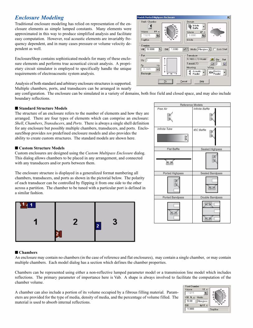
Enclosure ModelingTraditional enclosure modeling has relied on representation of the en-closure elements as simple lumped constants. Many elements wereapproximated in this way to produce simplified analysis and facilitateeasy computation. However, real acoustic elements are invariably fre-quency dependent, and in many cases pressure or volume velocity de-pendent as well.
EnclosureShop contains sophisticated models for many of these enclo-sure elements and performs true acoustical circuit analysis. A propri-etary circuit simulator is employed to specifically handle the uniquerequirements of electroacoustic system analysis.
Analysis of both standard and arbitrary enclosure structures is supported.Multiple chambers, ports, and transducers can be arranged in nearlyany configuration. The enclosure can be simulated in a variety of domains, both free field and closed space, and may also includeboundary reflections.
■ Standard Structure ModelsThe structure of an enclosure refers to the number of elements and how they arearranged. There are four types of elements which can comprise an enclosure:Shell, Chambers, Transducers, and Ports. There is always a single shell definitionfor any enclosure but possibly multiple chambers, transducers, and ports. Enclo-sureShop provides ten predefined enclosure models and also provides theability to create custom structures. The standard models are shown here.
■ Custom Structure ModelsCustom enclosures are designed using the Custom Multipass Enclosure dialog.This dialog allows chambers to be placed in any arrangement, and connectedwith any transducers and/or ports between them.
The enclosure structure is displayed in a generalized format numbering allchambers, transducers, and ports as shown in the pictorial below. The polarityof each transducer can be controlled by flipping it from one side to the otheracross a partition. The chamber to be tuned with a particular port is defined ina similar fashion.
■ ChambersAn enclosure may contain no chambers (in the case of reference and flat enclosures), may contain a single chamber, or may containmultiple chambers. Each model dialog has a section which defines the chamber properties.
Chambers can be represented using either a non-reflective lumped parameter model or a transmission line model which includesreflections. The primary parameter of importance here is Vab. A shape is always involved to facilitate the computation of thechamber volume.
A chamber can also include a portion of its volume occupied by a fibrous filling material. Param-eters are provided for the type of media, density of media, and the percentage of volume filled. Thematerial is used to absorb internal reflections.
Reference Models
IEC Baffle
Free Air
Infinite Tube
Infinite Baffle
Flat Baffle Sealed Highpass
Sealed BandpassPorted Highpass
Ported Bandpass Double Bandpass

EnclosureShop provides a catalog of pre-defined chamber shapes with automatic vol-ume calculation. The dimensional variablescan be assigned values by the user. The pro-gram will then compute the internal net vol-ume, including compensation for finite wallthickness.
Analysis of an enclosure produces severalcurves for each chamber in the enclosure,including the pressure response. Each curvemay be enabled/disabled for display depend-ing on the interests of the user. Examplesof chamber pressure curves are shown here.
Two pair of typical on-axis and chamberresponse curves are shown in the graphs,with 50% fill of fiberglass and 0% respec-tively. Chamber response curves are alwaysmuch higher than free field curves, sincethe radiation into the chamber is confined.
These graphs show the internal chamberreflections coming through the external on-axis response and clearly illustrate the ben-efits of the damping material used inside.
■ PortsAn enclosure may contain one or moreports, and each may represent either an airvent or drone passive radiator. Each modeldialog has a section which defines the portproperties for a particular location.
On-Axis Response
Internal Chamber
On-Axis Response
Internal Chamber
When the Fp field is clicked another dialog will open todefine the detailed parameters of the port as shown left.Different fields appear depending on vent or drone.
Vents can also include a fibrous filling material for ex-tra damping control, and to absorb reflections. Theseare similar to the chamber filling parameters. Ports canbe represented with either a lumped parameter or transmission line model.
Analysis of an enclosure produces five curves foreach port location in the enclosure. The near fieldport pressure SPL curve is shown here.
The analysis of port behavior can also include theeffects of standing wave reflections inside the port.This is shown by the two near field port curves inthe graph.
These reflections may or may not show up in theexternal enclosure response on-axis, depending onthe chamber and port design.
50% fill with 1lb Fiberglass
0% fill, or Air media only.
10 Hz 20 50 100 200 500 1K 2K 5K 10K
dBSPL
30
40
50
60
70
80
90
100
110
120
130SPL vs Freq
SPL-Near Port, no standing waves
SPL-Near Port, with standing waves
SPL-0H,0V Enc

Front View
Top View
1
2
3
45
678
9
10
11
Face #1
1.0
Vertex 1-12Around Top
Vertex 12-24Around Bottom
12
Side View
X
Y
X
Z
Y
Z
2.0
1.6
Sealed Highpass Sealed Bandpass
Shell ModelingThe concept of an external enclosure definition will probably be new to most readers. The shell of an enclosurespecifies the external shape and dimensions. This specification is necessary for diffraction analysis.
The shell of an enclosure may or may not bethe same as a chamber. For example, con-sider the two enclosure models shown here.The Sealed Highpass model has a singlechamber. The shell for this enclosure is sim-ply defined from the single chamber. How-ever, the Sealed Bandpass model has twochambers. Enclosures with multiple cham-bers require separate choices for the shell.
EnclosureShop provides a catalog of 18 predefined shell shapes, as shown here on the right. The dimensionalvariables for these shapes can be assigned values by the user. Thus the standard shells can be scaled or aspect ratioschanged to provide virtually unlimited numbers of different shells.
■ Imported Custom ShellsIt is also possible to import 3D definitions for the shell of any enclosure. Three file formats are supported: OBJ, DXF,and 3DS. The OBJ and DXF formats are text while the 3DS format is binary. The OBJ format was created by Alias/Wavefront (now Silicon Graphics Inc SGI) and is commonly used in the Maya program. Maya is one of the fewgraphics programs designed for true polygon editing and representation.
While it is possible to use many 3D CAD or graphics programs to work out the design of your enclosure shell, youwill probably find that very few are capable of exporting the object properly with the required clean polygon struc-ture. Most graphics programs do not allow polygon editing with the precision required. Even when you can createthe proper polygons, many do not provide a means to export the objects whole and will force tessellation.
However, a proper OBJ file can also be created relatively easily by manual means by using any text editor. In manycases this method may be the only or best choice. An example of generating a proper OBJ file is shown below. TheOBJ file used for this shell required only 37 lines of text. When generating the enclosure shell model for a physicalenclosure, some simplification is often appropriate and necessary. It is not important to model each and every detail.This would only complicate and lengthen the diffraction analysis. The contribution of any edge or face is roughlyproportional to its size on the enclosure. Therefore, small shell details are relatively insignificant.
Curved surfaces must be represented asone or more faceted flat planes. Theexample here shows the curved sides asa sequence of five flat vertical strips.The vertex nodes around the top and bot-tom of the shell are assigned numbersas shown below. The axis and origins areshown for each of the three views.
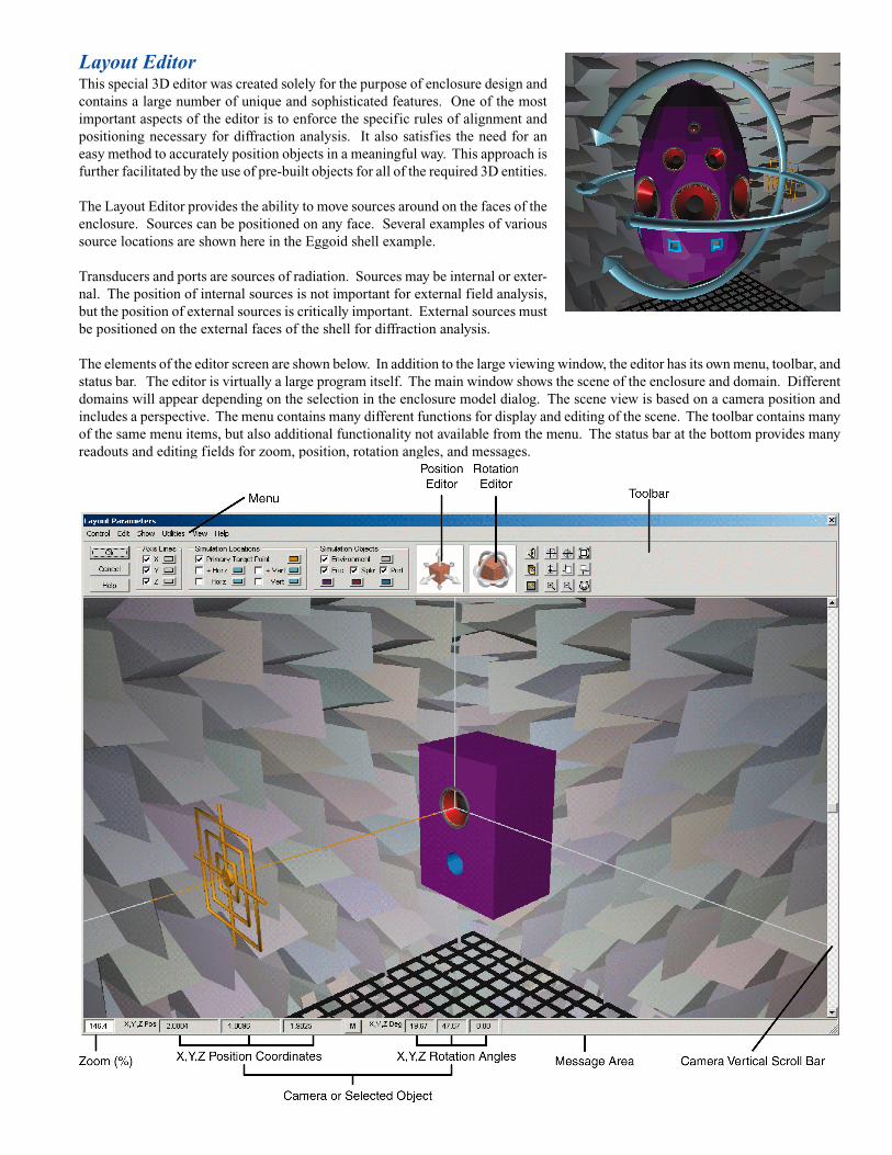
Layout EditorThis special 3D editor was created solely for the purpose of enclosure design andcontains a large number of unique and sophisticated features. One of the mostimportant aspects of the editor is to enforce the specific rules of alignment andpositioning necessary for diffraction analysis. It also satisfies the need for aneasy method to accurately position objects in a meaningful way. This approach isfurther facilitated by the use of pre-built objects for all of the required 3D entities.
The Layout Editor provides the ability to move sources around on the faces of theenclosure. Sources can be positioned on any face. Several examples of varioussource locations are shown here in the Eggoid shell example.
Transducers and ports are sources of radiation. Sources may be internal or exter-nal. The position of internal sources is not important for external field analysis,but the position of external sources is critically important. External sources mustbe positioned on the external faces of the shell for diffraction analysis.
The elements of the editor screen are shown below. In addition to the large viewing window, the editor has its own menu, toolbar, andstatus bar. The editor is virtually a large program itself. The main window shows the scene of the enclosure and domain. Differentdomains will appear depending on the selection in the enclosure model dialog. The scene view is based on a camera position andincludes a perspective. The menu contains many different functions for display and editing of the scene. The toolbar contains manyof the same menu items, but also additional functionality not available from the menu. The status bar at the bottom provides manyreadouts and editing fields for zoom, position, rotation angles, and messages.

Diffraction AnalysisWhen a wave strikes the surface of a hard object a reflection occurs. When awave strikes the edge of an object a diffraction occurs. Therefore, reflectionis associated with the area of a surface while diffraction is associated with theedge of a surface. These two types of phenomenon are shown here.
Here we see a point source radiating towards an object with a receiver locatedat another point in space. The acoustic pressure received at this location isthe sum of three different types of radiation: direct, reflected, and diffracted.
The contribution of the reflection wave generated by the surface of the object is relatively easy to compute. However, thediffraction wave is highly complex. It is dependent on the angle of the source, the angle of the receiver, and the solid angle ofthe wedge. The pictorial above shows only a two dimensional representation. The true physicalprocess requires complex three dimensional geometry.
In the case of a loudspeaker enclosure the transducer is generally mounted on the surface of awall as is represented here in the pictorial. In this special case the object is an enclosure, andboth the direct and reflected waves are identical. The wave striking the edge arrives from the90 degree off-axis radiation of the source. For this reason, the off-axis response of thetransducer must be represented with reasonable accuracy. All of the enclosure diffractionoriginates from the 90 degree off-axis transducer response.
The diffraction which occurs from the source to the first edgeis known as 1st order diffraction. However, real enclosureshave multiple edges. The diffracted wave leaving the firstedge strikes other edges producing higher orders ofdiffraction. The process is shown here in the pictorial for asingle path. In reality there are many paths.
The source radiates outward towards all of the edges around the baffle board. These edgesthen diffract and reradiate towards any adjacent edges. This process continues forever withdecreasing amplitude through each order of diffraction.
You may now be wondering what the on-axis detailed response looks like for different ordersof diffraction on a simple box. Note the graph below. As one would expect the 0th orderdiffraction shows major errors in the response. Actually, this is the exact infinite baffleresponse. With 1st order diffraction the response begins to take shape but is still in error by several dB at low frequencies. With2nd order diffraction the response becomes much more accurate. Further increases of diffraction order produce only smallimprovements. However, different shell designs can require much higher order diffraction analysis.
The polar graph below show the response using 4th order diffraction and a resolution of 6kHz. Using polar plots to evaluatediffraction analysis is invaluable. The response at all angles around the enclosure is obtained at once. Remarkable effects of shelldesign and transducer/port location can be examined in detail.
Source
Receiver
ReflectedWave
DiffractedWave
DirectWave
Object qw
qs qr Source
Receiver
DiffractedWave
Direct & ReflectedWave
Objectqw
Source
Enclosure
1st Order Diffraction
2nd Order Diffraction
3rd Order Diffraction
0o On-Axis
90o Off-Axis
SourceField
Diffr-1Field
(Diffr-1 & Diffr-2)
(Diffr-2) (Source & Diffr-1)
Diffr-1Field
Diffr-2Field
Diffr-2Field
FrontRcvr
SideRcvr
RearRcvr
Enclosure
10 Hz 20 50 100 200 500 1K 2K 5K 10K
dBSPL
45
50
55
60
65
70
75
80
85
90
95SPL vs Freq
Diffr-0
Diffr-1
Diffr-2Diffr-3
Diffr-4
Source Wave
0o On-Axis
90o Off-Axis
Diffraction Wave
-180
-165
-150
-135
-120
-105-90
-75
-60
-45
-30
-15
0 Deg
15
30
45
60
7590
105
120
135
150
165
180
dBSPL
45
50
50
55
55
60
60
65
65
70
70
75
75
80
80
85
85
90
90
95
95
80320640
1.28K2.56K3.84K5.12K6.40K
12.80K
Fr = 6000 HzDiffr Order = 4

SimulationMeasurement
Simulation
Measurement
SimulationMeasurement
On-Axis Response
SimulationMeasurement
Simulation
Measurement
Simulation
Measurement
Near-Field Response
Simulation
Measurement
Chamber Response
SimulationMeasurement100W
10W
1W
0.1W
15 In in Ported Box
Note difference in 100W curve pair below20Hz. This is due to the highly distortedwaveforms in the actual measurement, andthe assumption of sinusoidal waveforms inthe simulation. The large harmonic contentcannot be represented accurately by equiva-lent RMS sine wave analysis at this very highlevel of nonlinearity.
Simulation AccuracyThe graphs here demonstrate anassortment of simulation vs. mea-surement comparisons. A varietyof different graphs and data illus-trate the detail of the simulations.
100W
10W
1W
0.1W
SIMULATION
100W
10W
1W
0.1W
MEASUREMENT
SimulationMeasurement
Diffraction
Sim / InfBafSim / AnechoicMea / InfBafMea / Anechoic
Four curves are shown: the pair of simulations, and the pair of measurements.While they are similar the response at high frequencies is entirely different.The woofer model was not tuned to replicate the actual transducer used in thetest. However dividing the curves removes the common driver response dif-ferences and leaves the Diffraction as shown in Ratio curves above.

LINEARX SYSTEMS INC9500 SW Tualatin-Sherwood RdTualatin, OR 97062-8586 USA
Tel: 503-612-9565 Fax: 503-612-9344www.linearx.com [email protected]
Contact factory or visit our web site for alist of International Dealers.
All specifications subject to change without notice.© 2007 All Rights Reserved.Printed in the U.S.A.MAR-12-2007
EnclosureShop Highlights• Revolutionary Diffraction Engine
• Nonlinear Acoustic Network Simulator
• Arbitrary Structural Enclosure Analysis
• Standard or Custom Enclosure Structures
• Far Field, Near Field, Pressure Analysis
• Infinite or Finite Volume Domains
• Full, Half, Quarter, Eighth Space Domains
• 360 Degree Horiz/Vert Polar Field Simulation
• New Advanced LTD Transducer Model
• Multiple Transducer Models: STD, TSL, LTD
• Chamber Transmission Line Simulation Model
• Port Transmission Line Simulation Model
• Accurate Fill Media Characterizations
• Diaphragm Shape & Profile Characterization
• Diaphragm Directivity Off-Axis Simulation
• Transducer Acoustic Mount: Para/Ser/ParaSer
• Transducer Electrical Wire: Para/Ser/ParaSer
• Nonlinear Port Simulation & Analysis
• Nonlinear Transducer Simulation & Analysis
• Multiple Transducers/Ports per Chamber
• Multiple Chambers per Enclosure
• Chambers/Ports with Media Fill & Density
• Passive & Active Drone Ports/Speakers
• Volume Object Parameter Calculators
• Area Object Parameter Calculators
• Built-in Unit Conversions on All Parameters
• Specialized 3D Graphical Object Editor
• Automatic Enclosure Shell Generator
• Prebuilt Scalable 3D Enclosure Objects
• Enclosure Shell 3D Import/Export
• Transducer/Port 3D Location Editing
• Quick Design & Reverse Speaker Utilities
• Multi Curve Transducer Parameter Derivation
• Comprehensive 2-Volume Manual Set
System RequirementsEnclosureShop is an extremely intensive numerical application.The program contains literally hundreds of numerical mathematicsalgorithms, some of which are extremely large and place very highdemands on the CPU's floating point performance.
EnclosureShop will use all of the speed your processor has to offer,and probably want much more. The complexity of your design willlargely determine the amount of CPU power and memory required.For high order enclosures the program can consume the entireWin32 2GB address space. For more typical simple enclosures,memory usage runs anywhere from 50-250MB.
EnclosureShop also uses extensive graphics including OpenGL®3D display modes. For best results a 1024 x 768 video resolutionis suggested with 16 bit to 32 bit color depth. High quality modern3D video cards with hardware acceleration are strongly recom-mended.
Minimum System Requirements• Mouse and Keyboard• USB port for license key• Windows® 95, 98, SE, ME, NT4, 2000, XP• 250MB free Hard Drive space• 64MB RAM Memory• Pentium® II / 350 or equivalent• Video 800 x 600 Resolution / 64K Colors• OpenGL® 3D graphics support• TrueType® or Adobe® Fonts
Recommended System Requirements• Windows® 2000 or Windows® XP• 300MB free Hard Drive space• 256MB RAM Memory or more• Pentium® III / 1GHz or equivalent• Video 1024 x 768 Res / 24 or 32 bit Color• Nvidia® OpenGL® version 1.2 drivers• Adobe® Fonts with Adobe Type Manager®
Note: Due to the limitations of Win9X, not all of the program'sfeatures and/or capabilities will be available in those operatingsystems.