Losses due to Fluid Friction - جامعة نزوى · 2 Objectives To measure the pressure drop in...
32
1 Chapter 6 • Losses due to Fluid Friction
-
Upload
truongkien -
Category
Documents
-
view
218 -
download
4
Transcript of Losses due to Fluid Friction - جامعة نزوى · 2 Objectives To measure the pressure drop in...

1
Chapter 6
• Losses due to Fluid Friction

2
Objectives
To measure the pressure drop in the straight section of smooth, rough, and packed pipes as a function of flow rate.
To correlate this in terms of the friction factor and Reynolds number.
To determine the influence of pipe fittings on pressure drop
3
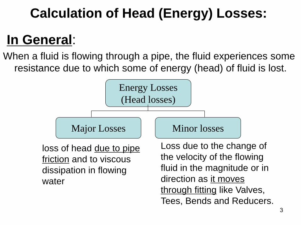
Calculation of Head (Energy) Losses:
In General: When a fluid is flowing through a pipe, the fluid experiences some
resistance due to which some of energy (head) of fluid is lost.
Energy Losses
(Head losses)
Major Losses Minor losses
loss of head due to pipe
friction and to viscous
dissipation in flowing
water
Loss due to the change of
the velocity of the flowing
fluid in the magnitude or in
direction as it moves
through fitting like Valves,
Tees, Bends and Reducers.

4
Losses due to Friction Mechanical energy equation between locations 1 and 2 in the absence of
shaft work:
For flow in a horizontal pipe and no diameter change (V1=V2), then :
21 PP
F
Thus, the shear
stress at the wall
is responsible for
the losses due to
friction
Losshg
zzg
V
g
V
g
P
g
P
F)()
22()( 21
2
2
2
121
Hagen-Poiseuille Law-E5.10
4
oD
128x QF
Because of (5.4) :
D
xF w
4
(6.13) (6.14)
m
Qu
Fwhere
=Friction head/unit mass
Or F/g= hLoss= 128μQL/(πρgD4)
g
PP
21
LhF/g
OR F in J/kg
and

5
Total head loss , hL (=F/g), is regarded as the sum of
major losses and minor losses
hL major, due to frictional effects in fully developed flow in
constant area tubes,
hL minor, resulting from entrance, fitting, area changes,
and so on.
Losses due to Friction

6
Losses due to Friction/The Friction Factor In order to determine an expression for the losses due to friction we must
resort to experimentation.
D
V LF
2
By introducing the friction factor, f:
D.2
V f
2LF
where
)2/)(/( 2VDL
Ff
(6.15)
where L=length of the pipe,
D=diameter of the pipe,
V=velocity,
2/
)/(2V
LDPf
or
21 PP
F
f is called Darcy friction factor

7
Friction Factor
0)2
(2
Lwork PPV
gzP
The Darcy friction factor f is defined as
We know the wall shear stress
2/
)/(2V
LDPf
L
PDτw
4
2/2Vf w
(E6-21)
The friction factor is the ratio between wall shear stress
and flow inertial force.
orLmajorLL PPP min,,
now later
and

8
Major Loss and Friction Factor
0)2
(2
Lwork PPV
gzP
With the introduction of friction factor, we can calculate major loss by
(E6-22) 2
2
,
V
D
LfP MajorL
Friction factor Pipe geometry factor Dynamic pressure
Therefore, our job now is find the friction factor f for various flows.
orLmajorLL PPP min,,

9
Friction Factor –
Case1: Laminar Pipe Flow For a pipe with a length of L, the pressure gradient is constant, the pressure drop
based on Hagen-Poiseuille Law ,
Dividing both sides by the dynamic pressure V2/2 and L/D
We have
2
42
4
4
/32
/)4/(128
/)(128
,/128
DVLP
DLDVP
DLVAP
VAQDLQP
Re
64f
Re
6464
2/
/32
2/
)/(2
2
2
VDL
D
V
DVL
V
LDPf

10

11
Example 1
losses in

12
According to Darcy

13
Example 2

14

15
Case 2: Turbulent Flow When fluids flow at higher flow rates, the streamlines are not steady, not
straight and the flow is not laminar.
Generally, the flow field will vary in both space and time with fluctuations
that comprise "turbulence”
When the flow is turbulent the velocity and pressure fluctuate very
rapidly. The velocity components at a point in a turbulent flow field
fluctuate about a mean value.
n
R
r
V
u/1
max
1
Time-averaged velocity profile
can be expressed in terms of
the power law equation, n =7
is a good approximation.

16
Friction Factor-Turbulent Pipe Flow •For a laminar flow, the friction factor can be analytically derived.
•It is impossible to do so for a turbulent flow so that we can only
obtain the friction factor from empirical results.
•In addition, most pipes, except glass tubing, have rough surfaces.
•The pipe surface roughness is quantified by a dimensionless
number, relative pipe roughness (ε / D ), where ε is pipe
roughness and D is pipe diameter.
•For laminar pipe flow, the flow is dominated by viscous effects
hence surface roughness is not a consideration.
•However, for turbulent flow, the surface roughness may emerge
beyond the laminar sublayer and affect the flow to a certain
degree.
•Therefore, the friction factor f can be generally written as a
function of Reynolds number and pipe relative roughness
There are several theoretical models available for the
prediction of shear stresses in turbulent flow.

17
Surface Roughness
Additional dimensionless group /D
need to be characterized
Thus more than one curve on friction factor-
Reynolds number plot
Fanning diagram or Moody diagram
Depending on the laminar region.
If, at the lowest Reynolds numbers, the laminar portion
corresponds to f =16/Re Fanning Chart
(or f = 64/Re Moody chart)

18
Pipe Surface Roughness
19
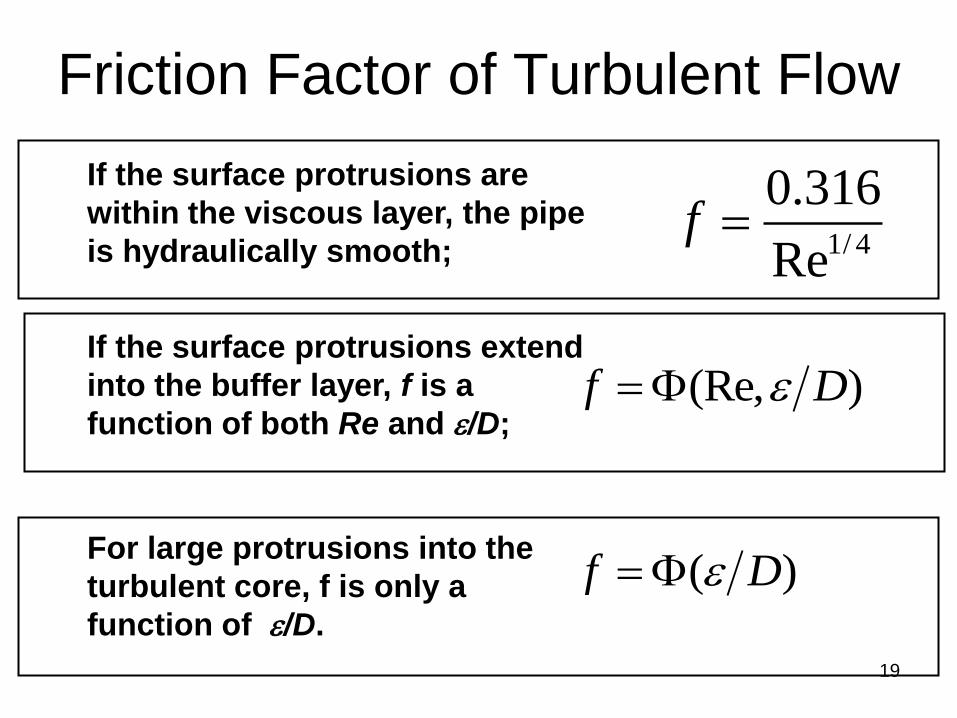
Friction Factor of Turbulent Flow
If the surface protrusions are
within the viscous layer, the pipe
is hydraulically smooth;
If the surface protrusions extend
into the buffer layer, f is a
function of both Re and /D;
For large protrusions into the
turbulent core, f is only a
function of /D.
)(Re, Df
)( Df
1/ 4
0.316
Ref
20
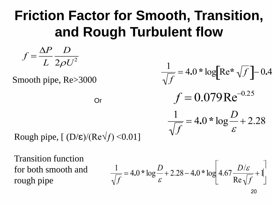
Friction Factor for Smooth, Transition,
and Rough Turbulent flow
1
f 4.0 * log Re* f 0.4
Smooth pipe, Re>3000
1
f 4.0 * log
D
2.28
Rough pipe, [ (D/ε)/(Re√ƒ) <0.01]
1
f 4.0 * log
D
2.28 4.0 * log 4.67
D /
Re f1
Transition function
for both smooth and
rough pipe
f P
L
D
2U 2
f 0.079Re0.25Or

21
Fanning Diagram
f =16/Re
1
f 4.0 * log
D
2.28
1
f 4.0 * log
D
2.28 4.0 * log 4.67
D /
Re f1

22
Friction Factor – The Moody Chart

23
Friction Factor – The Moody Chart

24
Example: Comparison of Laminar or
Turbulent pressure Drop
• Air under standard conditions flows through a 4.0-mm-
diameter drawn tubing with an average velocity of V = 50 m/s.
For such conditions the flow would normally be turbulent.
However, if precautions are taken to eliminate disturbances to
the flow (the entrance to the tube is very smooth, the air is dust
free, the tube does not vibrate, etc.), it may be possible to
maintain laminar flow.
• (a) Determine the pressure drop in a 0.1-m section of the tube
if the flow is laminar.
• (b) Repeat the calculations if the flow is turbulent.
Straight and horizontal pipe and same diameters give same velocity:
Z1=Z2=0 V1=V2 and thus Losshgp /

25
Solution1/2
flowTurbulent700,13.../VDRe
Under standard temperature and pressure conditions
=1.23kg/m3, μ=1.7910-5Ns/m
The Reynolds number
kPaVD
fp 179.0...2
1 2
If the flow were laminar and using Darcy friction
f=64/Re=`…=0.00467
kPaVD
fp 179.0...2
14 2
f=16/Re=`…=0.001167
If the flow were laminar and using Fanning friction

26
Solution2/2
kPaVD
fp 076.1...2
1 2
If the flow were turbulent
From Moody chart f=Φ(Re, smooth pipe) =0.028
From Fanning chart f=Φ(Re, smooth pipe) =0.007
kPaVD
fp 076.1...2
14 2

27
Example
Straight and horizontal pipe and same diameters give
same velocity:
Z1=Z2=0 V1=V2 and thus
pressurepumpghp Loss

28

29

30
Example: Determine Head Loss
• Crude oil at 140°F with γ=53.7 lb/ft3 and μ= 810-5
lb·s/ft2 (about four times the viscosity of water) is
pumped across Alaska through the Alaska pipeline, a
799-mile-along, 4-ft-diameter steel pipe, at a
maximum rate of Q = 2.4 million barrel/day = 117ft3/s,
or V=Q/A=9.31 ft/s. Determine the horsepower
needed for the pumps that drive this large system.

31
Solution1/2
The energy equation between points (1) and (2)
Assume that z1=z2, p1=p2=V1=V2=0 (large, open tank)
ftg
V
Dfhh PL 17700...
2
2
L2
2
22P1
2
11 hzg2
Vphz
g2
Vp
hP is the head provided to the
oil by the pump.
Minor losses are negligible because of the large length-
to-diameter ratio of the relatively straight, uninterrupted
pipe.
f=0.0124 from chart ε/D=(0.00015ft)/(4ft), Re=…..

32
Solution2/2
The actual power supplied to the fluid
power=Q∆P =Qρgh
unit of power (SI): Watt =N.m/s=J/s
hpslbft
hpgQhP 202000
/550
1...Power