LOOKING FOR DIAGNOSTICS PARAMETERS OF BEARINGS OF THE GAS ... · LOOKING FOR DIAGNOSTICS PARAMETERS...
7
TRANSPORT PROBLEMS 2009 PROBLEMY TRANSPORTU Volume 4 Issue 3 Part 1 Waldemar MIRONIUK Naval Academy ul. Śmidowicza 69, 81-103 Gdynia, Poland Corresponding author. E-mail [email protected] LOOKING FOR DIAGNOSTICS PARAMETERS OF BEARINGS OF THE GAS TURBINE ENGINE LM 2500 ON THE BASIS OF MECHANICAL CONTAMINATIONS IN THE LUBRICATING OIL Summary. While operation a gas turbine engine more modest methods of research are brought into effect. But one of the basic methods to estimate the technical condition of gas turbine engines bearing is oil analysis. To estimate the technical condition of gas turbine engines bearing systems on the basis of oil research on, an x-ray method of radio- isotope fluorescence was used. This method has been also satisfactorily used in aircraft engine diagnosis. This paper presents the method of diagnosis bearings of marine gas turbines on the basis of studies of mechanical contamination in oil. Results of mechanical contamination research in oil vs time of engine work are presented. On the basis of experiments results the analytical function that makes calculating the future value of the process possible was chosen. POSZUKIWANIE PARAMETRÓW DIAGNOSTYCZNYCH LOŻYSK SILNIKÓW LM 2500 NA PODSTAWIE BADAŃ ZANIECZYSZCZEŃ MECHANICZNYCH W OLEJU SMAROWYM Streszczenie. W eksploatacji okrętowych silników turbinowych powszechnie stosowane są coraz nowsze metody badań diagnostycznych. Jednak jedną z podstawowych metod nadzoru stanu technicznego silników są analizy olejowe. W badaniach diagnostycznych silników turbinowych na podstawie zanieczyszczeń metalicznych w oleju zastosowano, wcześniej wdrożoną w lotnictwie wojskowym, metodę rentgenowskiej fluorescencji radioizotopowej XRF. Metoda ta stanowi użyteczne narzędzie w ocenie stanu technicznego ukladów mechanicznych silnika. W referacie przedstawiono krótki opis metodyki badań diagnostycznych okrętowych turbinowych silników spalinowych. Do badań identyfikacji zanieczyszczeń mechanicznych w oleju smarowym wykorzystano spektrometr fluorescencyjny ZBZ 93 dzialający w oparciu o fluorescencję rentgenowską XRF. W artykule zaprezentowano wyniki badań zanieczyszczeń oleju pierwiastkami Fe i Cu, jako funkcje czasu pracy silników turbinowych. Na podstawie otrzymanych wyników badań eksperymentalnych przedstawiono linie trendu wartości zmian tych parametrów w czasie oraz zaprezentowano, opracowany na podstawie badań oleju, parametr diagnostyczny lożysk silnika.
Transcript of LOOKING FOR DIAGNOSTICS PARAMETERS OF BEARINGS OF THE GAS ... · LOOKING FOR DIAGNOSTICS PARAMETERS...

TRANSPORT PROBLEMS 2009 PROBLEMY TRANSPORTU Volume 4 Issue 3 Part 1
Waldemar MIRONIUK
Naval Academy ul. Śmidowicza 69, 81-103 Gdynia, Poland Corresponding author. E-mail [email protected] LOOKING FOR DIAGNOSTICS PARAMETERS OF BEARINGS OF THE
GAS TURBINE ENGINE LM 2500 ON THE BASIS OF MECHANICAL
CONTAMINATIONS IN THE LUBRICATING OIL
Summary. While operation a gas turbine engine more modest methods of research are brought into effect. But one of the basic methods to estimate the technical condition of gas turbine engines bearing is oil analysis. To estimate the technical condition of gas turbine engines bearing systems on the basis of oil research on, an x-ray method of radio-isotope fluorescence was used. This method has been also satisfactorily used in aircraft engine diagnosis.
This paper presents the method of diagnosis bearings of marine gas turbines on the basis of studies of mechanical contamination in oil. Results of mechanical contamination research in oil vs time of engine work are presented. On the basis of experiments results the analytical function that makes calculating the future value of the process possible was chosen.
POSZUKIWANIE PARAMETRÓW DIAGNOSTYCZNYCH ŁOŻYSK SILNIKÓW LM 2500 NA PODSTAWIE BADAŃ ZANIECZYSZCZEŃ MECHANICZNYCH W OLEJU SMAROWYM
Streszczenie. W eksploatacji okrętowych silników turbinowych powszechnie stosowane są coraz nowsze metody badań diagnostycznych. Jednak jedną z podstawowych metod nadzoru stanu technicznego silników są analizy olejowe. W badaniach diagnostycznych silników turbinowych na podstawie zanieczyszczeń metalicznych w oleju zastosowano, wcześniej wdrożoną w lotnictwie wojskowym, metodę rentgenowskiej fluorescencji radioizotopowej XRF. Metoda ta stanowi użyteczne narzędzie w ocenie stanu technicznego układów mechanicznych silnika.
W referacie przedstawiono krótki opis metodyki badań diagnostycznych okrętowych turbinowych silników spalinowych. Do badań identyfikacji zanieczyszczeń mechanicznych w oleju smarowym wykorzystano spektrometr fluorescencyjny ZBZ 93 działający w oparciu o fluorescencję rentgenowską XRF. W artykule zaprezentowano wyniki badań zanieczyszczeń oleju pierwiastkami Fe i Cu, jako funkcje czasu pracy silników turbinowych. Na podstawie otrzymanych wyników badań eksperymentalnych przedstawiono linie trendu wartości zmian tych parametrów w czasie oraz zaprezentowano, opracowany na podstawie badań oleju, parametr diagnostyczny łożysk silnika.
90 W. Mironiuk 1. INTRODUCTION
While operating a ship’s gas turbine engine friction elements like engine bearings play a main
role. The good technical condition of bearings has influence on the reliability of the engine and a warship’s combat readiness.
Damage bearings are the reason of an engine’s failures very often. Products of wear are gathered in oil. The example of damaged bearings of gas turbine engines are shown in the fig. 1 [7].
The direct reason of tribological system wear acceleration is always bad quality of lubricate. Hence a change of both physical and chemical characteristic of oil and concentration of mechanical contamination (a size and a morphology foreign body substance) included in oil can be index of the assessment of the oil useful characteristic. Therefore, oil is very valuable carrier information of both the reasons and the processes engine tribological system and oil wear.
Fig. 1. The examples of bearings damage Rys. 1. Przykłady uszkodeń łożysk tocznych
On the basis of the chemical analysis composition oil samples from the oil system, the monitoring
of mechanical contaminants change and conduct assessment of the technical state of interact engine parts is possible. 2. THE METHOD OF OIL EXPERIMENTAL RESEARCH
The detection of the state before the damage of interact tribological system parts of gas turbine
engine or an index of oil wear is possible on the basis of permanent or temporary contamination detection include in oil. The mechanical parts discharged from the engine tribological system gives the information about their technical state. The moving of both oil and contaminants can detect these contaminants direct in oil system or in the laboratory after taking oil sample from the engine. The research on contaminants in oil is conducted at the laboratory of the Naval Academy.
The X-ray radioisotope fluorescent method was used to estimate a quantity change of mechanical contaminants in oil. Thanks to induce and measurement of the characteristic intensity radiation, of this method, the chemical composition of oil samples was analyzed. The quantity analysis, it means identification of element, was conducted on the basis of measurement energy radiation this element but quantity estimate was led on the basis of the intensity radiation energy line. The characteristic radiation measurements are made by measuring system shown in the fig. 2.
There are two filters used to reduce the influence of other elements on the results of the analysis: - cobalt (Co) filters for determining of iron quantity, - aluminium (Al) filters for determining of copper quantity.

Looking for diagnosis parameters of bearings of the gas... 91 3. METHODOLOGY OF ESTIMATING THE OIL CONTAMINATION
Oil samples are collected from LM 2500 engines after every return the ship from the sea for the analysis. The scheme of the stand for mechanical impurities in oil analysis is shown in the fig. 3.
The stand bad is equipped with: - the fluorescence spectrometer ZBZ-93, - the stereoscopic microscope MST-3, - filtering device EB-1M/ITWL.
Fig. 2. XRF measuring device scheme:1 – filter, 2 – isotopic radiation source, 3 – Al or Co filter, 4 – detectors
window , 5 – detector Rys. 2. Schemat ogólny budowy sondy pomiarowej XRF: 1 – badany sączek, 2 - źródło promieniotwórcze, 3 –
filtr Al lub Co, 4 – okno detektora, 5 – detektor – licznik proporcjonalny
Fig. 3. The scheme of the stand for mechanical impurities in oil analysis Rys. 3. Schemat stanowiska do badań zanieczyszczeń mechanicznych w oleju
Two methods were adopted to determine quantity and quality of wear products in oil samples in the basic diagnostic system of marine gas turbine engines:
- stereoscopic microscopy, - x-ray radioisotope fluorescence. Oil collected from the ship was filtered in filtering device EB-1M/ITWI (fig.4) using filters „coli-
5”.
LABORATORYWARSHIP
Oil tank
OIL SAMPLE
FILTERING DEVICE
EB-1M/ITWL
Stereoscopic
microscope
MST-3
FLUORESCENCE SPECTROMETER ZBZ-93
FILTER
Archive
photos
92 W. Mironiuk
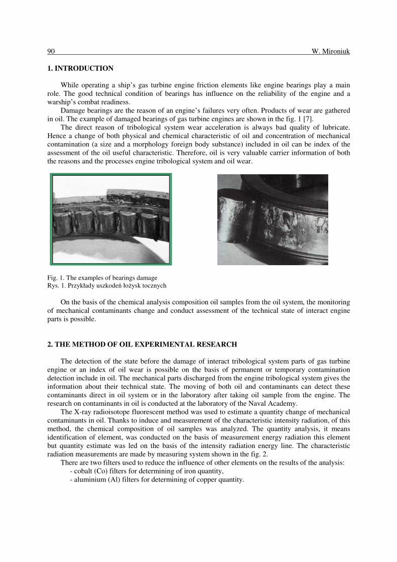
The filter was watched under the stereoscopic microscope MST-3 twenty four hours later. Owing to that, types and sizes of wear particles and changes in their quantity were determined with high precision. Optical examination allows to estimate oil contamination with water, graphite and makes it possible to identify the type and place of wear arising. The photo of the contaminant in the oil drain is shown in the fig. 5.
Fig. 4. Filtering device EB-1M/ITWL: 1 - air pump, 2 - filtering cylinder, 3 - reduction valve, 4 - manometer. Rys. 4. Przyrząd do filtrowania oleju typu EB-1M/ITWL: 1 - pompa powietrza, 2 - cylinder filtrujący, 3 - zawór redukcyjny, 4 - manometr
Fig. 5. The microscope view of the contaminant on the oil sample Rys. 5. Zanieczyszczenia oleju na sączku obserwowane pod mikroskopem
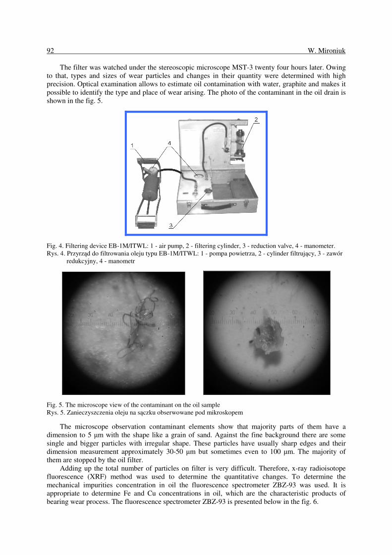
The microscope observation contaminant elements show that majority parts of them have a dimension to 5 µm with the shape like a grain of sand. Against the fine background there are some single and bigger particles with irregular shape. These particles have usually sharp edges and their dimension measurement approximately 30-50 µm but sometimes even to 100 µm. The majority of them are stopped by the oil filter.
Adding up the total number of particles on filter is very difficult. Therefore, x-ray radioisotope fluorescence (XRF) method was used to determine the quantitative changes. To determine the mechanical impurities concentration in oil the fluorescence spectrometer ZBZ-93 was used. It is appropriate to determine Fe and Cu concentrations in oil, which are the characteristic products of bearing wear process. The fluorescence spectrometer ZBZ-93 is presented below in the fig. 6.
Looking for diagnosis parameters of bearings of the gas... 93
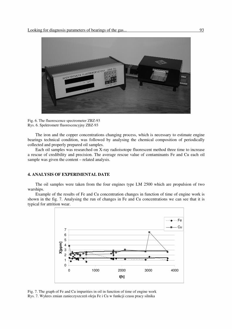
Fig. 6. The fluorescence spectrometer ZBZ-93 Rys. 6. Spektrometr fluorescencyjny ZBZ-93
The iron and the copper concentrations changing process, which is necessary to estimate engine
bearings technical condition, was followed by analysing the chemical composition of periodically collected and properly prepared oil samples.
Each oil samples was researched on X-ray radioisotope fluorescent method three time to increase a rescue of credibility and precision. The average rescue value of contaminants Fe and Cu each oil sample was given the content – related analysis.
4. ANALYSIS OF EXPERIMENTAL DATE
The oil samples were taken from the four engines type LM 2500 which are propulsion of two
warships. Example of the results of Fe and Cu concentration changes in function of time of engine work is
shown in the fig. 7. Analysing the run of changes in Fe and Cu concentrations we can see that it is typical for attrition wear.
0
1
2
3
4
5
6
7
0 1000 2000 3000 4000
t[h]
X[p
pm
]
Fe
Cu
Fig. 7. The graph of Fe and Cu impurities in oil in function of time of engine work Rys. 7. Wykres zmian zanieczyszczeń oleju Fe i Cu w funkcji czasu pracy silnika

94 W. Mironiuk
The methodology used to the assessment oil contaminants makes possible changes following Fe and Cu concentration but it does not inform us about the impurities value generated from the individual source. Therefore, the choice of the place to take oil samples from the oil system was the important stage of the research. Two places were chosen after the carefully analysis of the oil system construction and taking into consideration the possibility of bearings technical condition estimation: - the bearings oil supply; from the oil supply filter,
- the bearings scavenge oil; from the oil pomp.
The scheme shown below in the fig. 8 presents the engine oil system with chosen places to take oil samples.
Fig. 8. The lube oil system block diagram with the marked places to take oil samples; 1 - the oil tank; 2 - the lube
supply filters; 3 - the oil pump; 4 - the scavenge filters; 5 - the gas turbine engine; 6,7 - places to take oil samples
Rys. 8. Schemat instalacji olejowej silnika z zaznaczeniem miejsca poboru próbki oleju; 1 - zbiornik oleju; 2 -filtr oleju; 3 - pompa olejowa; 4 - filtr oleju odprowadzonego z silnika; 5 - silnik; 6, 7 - miejsca poboru oleju
The value of Fe and Cu concentration in oil samples taken from marked places is shown as the
form of graph in the fig. 9.
0
0,5
1
1,5
2
2,5
1 2
X[p
pm
]
Fe
Cu
Fig. 9. The graph of Fe and Cu impurities in oil taken from chosen places of oil system: 1 - oil sample taken from the lube supply filter, 2 - oil sample taken from the oil pump
Rys. 9. Wykres zanieczyszczeń pierwiastkami Fe i Cu oleju pobranego z instalacji olejowej silnika: 1 - próbka oleju pobrana z filtra oleju silnika, 2 - próbka oleju pobrana z pompy olejowej silnika

Looking for diagnosis parameters of bearings of the gas... 95
Fig. 9 presents a difference of Fe and Cu contaminations in the oil sample, taken from the lube supply filter (1) and the oil pump (2). On the basis of the received results, we can conclude that bearings are the main source of contaminants generated to oil the engine’s. Hence, we should observe a difference of both, Fe and Cu value, in the oil samples taken from the oil supply filter and the oil pump to estimate a technical condition of gas turbine engines bearings.
The difference marked, as ∆X parameter, calculated from the mathematical formula (1) can be a diagnosis measure of the gas turbine engine bearing system [5].
∆X = X1 – X2 (1)
where: X1- the Fe and Cu concentration in oil taken from the lube supply filter; X2- the Fe and Cu concentration in oil taken from the pump.
To receive diagnosis results of engines bearings oil contaminants research on ought to lead on the basis of oil samples taken from the oil supply filter and the oil pump. The observation of change of the ∆X diagnosis measure, while operating the engines process, enables the assessment of technical condition its bearings. The analytical function, which makes calculating future value of ∆X diagnosis measure, can be worked out on the basis of experiments’ results and will prevent bearing damages.
5. CONCLUSIONS
The results of experimental research confirmed the accuracy of measuring the Fe and Cu impurities concentrations levels in oil for diagnosis of marine gas turbine engines bearings.
The analysis of concentration of wear products in grease oil samples by x-ray radioisotope fluorescence (xrf) enables the control of wearing away the rubbing parts of an engine smeared with oil.
The worked out mathematical formula of ∆X parameter changes properly corresponds to a run of wearing processes taking place in bearings. It enables to forecast the failures of the bearings.
The worked out methods compared with traditional methods make possible to estimate the technical condition of marine gas turbine engines bearings without withdrawl of ships from exploitation and without disassembly of the engines.
References
1. Baczewski K.: Tribologia i płyny eksploatacyjne. WAT Warszawa, 1994. 2. Charchalis A.: Systemy pomiarowe wykorzystywane w diagnostyce okrętowych turbinowych
silników spalinowych. XV Międzynarodowe Sympozjum Siłowni Okrętowych. AMW, Gdynia; 1993, str. 16.
3. Korczewski Z.: Identyfikacja procesów gazodynamicznych w zespole sprężarkowym okrętowego
turbinowego silnika spalinowego dla potrzeb diagnostyki. Gdynia, Zeszyty Naukowe AMW, nr 138 A, 1999, str. 163.
4. Lewitowicz J.: Badanie produktów zużycia w systemach trybologicznych. ITWL, Warszawa, 1982. 5. Mironiuk W.: Ocena stanów awaryjnych układów łożyskowych okrętowych turbinowych silników
spalinowych. Rozprawa doktorska. AMW, Gdynia, 1995. 6. Piotrowski I.: Okrętowe silniki spalinowe. Wydawnictwo Morskie, Gdańsk, 1983. Received 3.11.2009; accepted in revised form 14.07.2009