-LONGthehistoryofrecording.com/Magazines/db Magazine/DB-1983... · 2013. 11. 18. · Ampex Cover...
76
Transcript of -LONGthehistoryofrecording.com/Magazines/db Magazine/DB-1983... · 2013. 11. 18. · Ampex Cover...

R O D Uiì.GiJ N THE SMART MIC* SYSTEM
The most troublesome audio conditions can only be solved by today's most trouble free microphone system.
The Shure Automatic Microphone System. Total integration is the key.
For the first time ever, Shure has combined micro- phone, mixer and logic technology in a dedicated, totally integrated system -so advanced, its conception marks the beginning of a sound revolution in conference rooms, teleconferencing, churches, legislative cham- bers, courtrooms- anywhere speech related multi - microphone systems are employed.
At the heart of Shure's Automatic Microphone System (AMS) are revolutionary, angle- sensitive microphones that turn on automatically only when addressed within their own 120° "window of accep- tance." In addition, each microphone continuously samples its own local acoustic environment, and compensates for changing room audio conditions - automatically.
The Shure AMS incorporates advanced signal processing circuitry- turning on to the sound source quickly, quietly, and automatically -and turning off with a smooth whisper. From
beginning to end -no clicks, pops, noise "pumping," or missed syllables.
Logic terminals on the rear panel of every AMS mixer offer unprecedented flexibility for advancing the system's capabilities. For example, when connected with Shure's Video Switcher Interface, the AMS will control commercially available video switchers. And for large gatherings, AMS mixers (both 4 and 8 channel models available) can easily be combined to effectively control over 200 individual microphones.
Since the AMS operates as an integrated system, many adjustments and controls have been eliminated. As a result, no other unit sets up as quickly. And operation is so easy and automatic, the only adjustments necessary are individual volume controls.
For more information on the revolutionary new Automatic Microphone System, call or write Shure Brothers Inc., 222 Hartrey Ave., Evanston, IL 60204, (312) 866 -2553.
'Microphones and Intelligent Circuitry
5HUE THE SOUND OF THE PROFESSIONALS ...WORLDWIDE
Circle 10 on Reader Service Card
PATENTS PENDING
SBI -1086A

Publisher Larry Zide
Associate Publisher Elaine Zide
Editor John M. Woram
Managing Editor Mark B. Waldstein
Associate Editor Ricki Zide
Technical Editor Linda Cortese
European Editor John Borwick
Layout & Design Kathi Lippe
SEPTEMBER 1983 VOLUME 17 NO. 8
FEATURES
RECORDING STUDIO CONSOLES AND FILM PRODUCTION 42
db TEST REPORT: THE BRUEL & KJAER STUDIO MICROPHONES 46
Gregory Hanks
John Monforte
LONG PLAYERS -LONG GONE John T. Mullin 48
HOUSE SOUND REINFORCEMENT AT THE US FESTIVAL 52
Bob Anthony
COMPACT DISC ANALYSIS Michael Tapes 56
SPARS -DATA TRACK 59
Advertising Coordinator Karen Cohn
Book Sales LETTERS CALENDAR EDITORIAL CLASSIFIED Lydia Calogrides 8 40 71
Circulation Manager THEORY AND PRACTICE Ken Pohlmann Eloise Beach 10
Len Feldman
K &S Graphics DIGITAL AUDIO Barry Blesser
DEPARTMENTS
SOUND WITH IMAGES Graphics 19
28 Typography
Spartan Phototype Co. SOUND REINFORCEMENT John Eargle 37
NEW PRODUCTS AND SERVICES 67
PEOPLE, PLACES, HAPPENINGS 73
db. the Sound I.ugmccnng MagannciISSS 00 I I -7 145) o published monthly by Saganwrc Publishing Company. Inc Fnurecon- tenta cops ghl' 198íb) Sagamore Publishing Co. 1120 Old( bunts Road. Plains less. I.. I_ N.Y. 11801. telephone IS 16)4116530 db o published tor those indu ¡duals and III ms m prulessional audio -recording. broadcast. audio -s oval, sound reinlorcement. con. ,uhant,. s ideo recording. Idm sound, etc. Applicat rm should be made on the subscription lorm in the rear 01 each issue. Nubamp eons aie S I S.00 per year (528.00 per year outside U.S. Possessions: SI6.00 per year Canada) in II.S. funds. Single copies are SI 9S
each I ditto ral. l'ubhshrng and Sales Olhces: 1 120 Old (ountr1 Road, Plains Jew . New York I ISO). Controlled circulation postage paid at Plainucu. NY 1180.1 and an additional mailing °lice. G5

MAGIC OR TRAGIC? To THE EDITOR:
Your June editorial about the pos- sible advent of the "Tragic of Digital" should be carefully studied by those making digital recordings. If the pub- lic is going to pay the extra cost for CDs, they will demand recordings of superior quality. I hope the recording industry will be able to make the transi- tion to digital technology. However, it will require that a number of people start carefully listening to the records that they are making.
STEPHEN M. HEIDER Buffalo, New York
WOW, WE NEED HELP TO THE EDITOR:
First, my thanks for a very informa- tive magazine. It helps expatriates like myself keep in touch with what's hap- pening in pro' audio.
We need some help here at TWR (Trans -World Radio) in Swaziland. We have an identifying signal, and we would like to eliminate tape noise and wow- and -flutter when we transmit it. The signal is used at station sign -on, when three 15- second phrases are played by handbells, followed by a 5- second voice ID. This sequence is repeated for about five minutes. At sign -off, we transmit a single 15- second handbell phrase.
If it is possible, we'd like to have these two signal formats digitized, and loaded into EPROMs. This should give us computer call -up as needed, as well as good reproduction. We already have the automation needed to provide the commands.
We would like to hear from anyone able to EPROM our "pingles," and please -by AIR MAIL. Surface mail takes about three months.
CAL DONNER, Studio Manager Trans -World Radio P.O. Box 64 Manzini, Swaziland
db replies: Hom about it readers? Can anyone
.. help TWR?
MAKING A POINT (FOUR, ACTUALLY) TO THE EDITOR:
Please permit me to make four com- ments regarding Mr. Levinson's letter in June's db.
First, I did not provide Mr. Levinson with copies of our two patents or any test data. Mr. Codomo may have done so, which of course is quite alright.
Second, I did not conduct the experi- ments; they were conducted by certified clinical audiologists, a very competent otologist, and a very knowledgeable neurologist. There was no possibility of any patient deriving answers to the word discrimination tests (the ultimate test of any hearing aid) by means of lip reading, sign language, or cue cards; all the patient's information had to come to him through the Cortical Hearing Aid. In no case did I work directly with a patient; only the audi- ologist and the otologist did that. (I only designed and built the equipment.)
Third, the conclusions presented in my article were the unanimous con- clusions of the audiologists, the otologist, and the neurologist referenced in the acknowledgments. I am profoundly grateful to all of them for their active involvement in the tests.
Fourth, I am always amazed at the reluctance of some people to try out new ideas, especially when there is no risk of any kind involved. Several times Mr. Codomo has cordially invited Mr. Levinson to view the Cortical Hearing Aid in action, but Mr. Levinson has always refused. If he wishes to visit us at Biophysical Research sometime to witness tests, he will be most welcome.
CURTISS B. SCHAFER Director of R & D Biophysical Research, Inc.
DON'T FORGET AMBISONICS To THE EDITOR:
Re: Len Feldman's article "Sound with Images," May 1983. I believe any discussion on Surround Sound tech- niques (whether applied to disc, video, or FM /TV broadcasting) should at least make mention of the "Ambisonics
Ondoz OO U
QdderrUs ° rrs
Altec 35 Alpha Audio 8 Amber 28 Ampex Cover III. IV Audio -Technica 21 BASF 9 Capitol Magnetic Prods. 13 Crown 5 David Haller Co. 14 Design Direct Sound 38 Electro -Voice 31 Emilar 20 Garner 30 Gotham Audio 36 -37 ITT Cannon 23 JBL 41 Klark -Teknik 6 Meyer Sound Labs 12 Orban 16 Otari 7. 25 PAIA 34 Polyline 34 Production EFX Library 48 QSC 26-27 Recording Studio Equipment Co.. 33 Renkus -Heinz 24 Rupert Neve 15 Saki Magnetics 22 Shure Bros. Cover II Sony 29 Standard Tape Lab 51 Studer Revox 11 Telex 19
Waters Mfg. Inc. 49 Yamaha 18
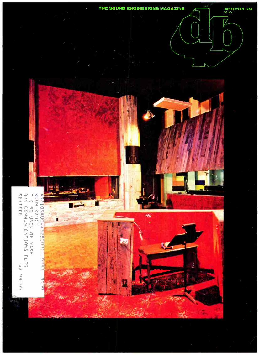
This month's cover features Studio A of Sound Emporium Recording Studios in Nashville, Tennessee. Studio A fea- tures a Harrison 3232 AB console, 2 -track and 24 -track Studer tape ma- chines, Sierra Monitors, and Altec, BGW, McIntosh, and Sony monitor am- plifiers. Artists who have recorded in Studio A include Johnny Cash, the Marshall Tucker Band, and Kenny Rogers. The photograph was taken by John Fleming.
MORE RECORDING STUDIOS USE CROWN MONITOR AMPS THAN ANY OTHER BRAND.
If you're going for gold, you've got to have the best - the best talent, the best writing, the best equipment. You'll leave nothing to chance.
That's why most studio professionals choose Crown monitor amplifiers.
They know they'll get the clearest highs, the most accu- rate mid -range, the most solid lows with Crown amps.
Sonic accuracy has always been the first goal - and the hallmark - of Crown engineer- ing. Crown amps are powerful,
but never at the loss of sonic accuracy. Crown amps are reliable, but our first concern is sonic accuracy.
Crown amps will never get in the way of the music. With Crown, you'll know for sure when you've got a gold.
.see BilltmanA International Recording Equipment & Studio Directory. 1982 -1983. crown®
1718 West Mishawaka Road, Elkhart, IN 46517 (219) 294 -5571 Circle 13 on Reader Service Card

Sound System" developed with support from the National Research Develop- ment Corporation of Great Britain.
Ambisonics may be encoded using: 2 Channels -good Surround Sound; 3 Channels -the additional channel
allowing a further improved illu- sion with sharper images;
2'h Channels -in practice, because the basic two channel version gives such good results, it is possible to obtain the further 3 channel im- provements with only limited audio bandwidth (hence the additional '/z channel). In broadcasting, this extra ,h channel can, of course, be transmitted in a stereo multiplex signed by additional modulation of the 38 kHz sub -carrier;
4 Channels -for full- sphere repro- duction including all angles of elevation and depression.
Needless to say all forms of encoding are totally mono /stereo compatible.
Ambisonic hardware not only in- cludes the Calrec Ambisonic Sound - field microphone, but also the Abacoid Professional Decoder, the Audio + De- sign Professional Decoder, Trans - coder, and (Multitrack) Pan Rotate units as well as various domestic decoders.
Further information can be obtained by contacting any of the manufacturers, including Audio + Design, P.O. Box 786, Bremerton, WA 98310 Tel: (206) 275- 5009.
NIGEL BRAN WELL Vice President Audio + Design Recording, Inc.
NOT SO DULL AFTER ALL To THE EDITOR:
Enclosed is my check for three more years. If I found db "dull" (see our January editorial -Ed.), I wouldn't be renewing my subscription.
I don't find it too technical either. As for the reviews, I think they're very good. Ken Pohlmann did an excellent job in the March issue (on the MCI JH -800 console). If I only had the kilo - bucks, I'd buy one. However, don't forget the little guys either. Precision Electronics in Franklin Park, Illinois, has a new mixer coming out this fall. Maybe you could take a look at it.
I'll close by saying...you can't please everyone. Even the Good Lord couldn't do it.
Keep db coming! HARVEY FULLINGTON Oak Creek, Wisconsin
db replies: Thanks for the kind words, Harvey.
And we wouldn't dream of trying to please everyone. We've even stopped trying to please the publisher. As for Ken. Pohlmann, he hasn't been pleased since we made him give back that console.
The newt step 3 f? in digital deIay-434 m sec.
f sti
Introducing the DN700 from Klark- 'l'eknik Research. This is the first of a new series of innovative micr)pnK'es.MH- controlled Digital Delay Lines with new and better prim:pe .1nrnlan(Y' ratio - bringing true professional perfurmanre in delay circuitry ,c Rhin reach of + maws than k before.
DN700 is a rack mounted 1 -in 3 -out unit giving easily adjusted delays up to 434 milliseconds, primarily for sound reinforcement applications. Features include non - volatile memory, an auto -diagnostic facility, and tamperproof lockout - with a minin)um resolution of 26. ; ' 'roseconds.
Sixrcificat includes: Frequency response +0.3 - 1.0dB 20117.-15kHz Dynamic range 2011z -20kHz
'cighledl. Better than 85dB Distortion l'l'HD) ©1kHz + tOdBm <0.05% for any delay length.
The Klark -Teknik promise -a bigger investment in the future with: 1. Greater R&D investment, with 12% of all company personnel directly invoked in new product development. 2. Consistent attention to production economies for professional performance at 'breakthrough' prices. 3. Effective 'Reliability Control' during manufacture.
tan TEK111 sne miR
ISrilisl, ,Irsip(nr,l, ISrüisl, in:,cl
DN 700 :
C 40fivow ̀
I. factored by Klark -Teknik Research Limited Coppice Trading Estate, Kidderminster DV I 1 71D, England. 'telephone: (0562) 741515 Telex: 339821
Klark -Teknik Electronics Inc. 262a Eastern Parkway, Farmingdale, NY 11735, USA. Telephone: 151M 249 -3660
Circle 14 on Reader Service Card
Omnimedia Corporation Limited 9653 (:ate de Liesse /Dorval, Quebec H9P 1A3 Canada. Telephone: 1514) 636 9971

TECHNOLOGY YOU CAN TOUCH
'The Otani MTR -10 Series 0" & /" Mastering/Production Recorders
The MTR -10 Series are fully microprocessor controlled mastering /production recorders available in four recording
formats: 1/4" full-track; 1/4" two channel; 1/2" two channel and 1/2" four channel. They are the ultimate
in analog tape recorder performance and are the embodiment of our dedication to innovation and qual-
ity. Practical, efficient and exclusive transport and elec- tronic features abound. Unprecedented control and
flexibility are now yours because they are the only mastering recorders in their class which feature an extremely sophisticated, full- function, ten memory locator. For the stringent requirements of multi -media production all versions of the MTR -10 Series machines easily interface with any SMPTE- based video editing system, machine controller or ;
synchronizer. A Working closely with industry leaders in broadcast,
film and recording production, we have engineered a recorder that is ready to meet any audio professional's chal- -III` lenge. Superb reliability, the hallmark of Otari's reputation, assures a profes- sional's investment in today's business... secures it for tomorrow's.
The MTR -10's are engineered like no other tape machines in the world; with the qualities you can hear and feel.
[REDO Technofogy You Can Touch. Otari Corporation, 2 Davis Drive, Belmont, CA 94002 Tel: (415) 592-8311 Telex: 910-376-4890 i1-
z
1
e
Come Help Us Celebrate The Child St. Jude Children's Research Hospital continues
its search for life- saving knowledge about childhood disease because people like you care. The cost of treatment, equipment and research programs is met primarily by public contributions.
Help us celebrate the children of the world with your check or request for further informa-
tion to St. Jude, 505 N. Parkway, Memphis, TN 38105. .-
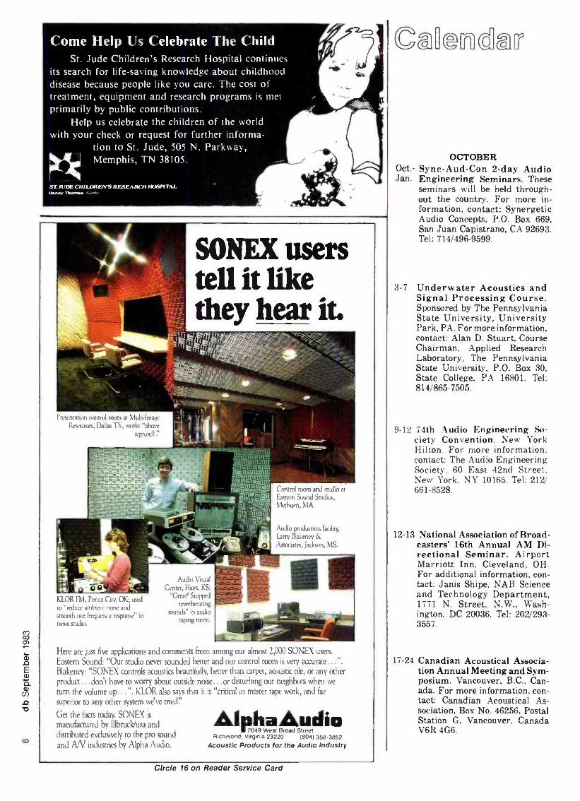
SONEX users tell it like they hear it.
Presentation control room at Muin -Imaic Resources, Dallas TX: works "above
Lontrol rann and'tudm Eastern Sound Studios, Methuen, MA.
Audio production facility,
Larry Blakeney & Associates, Jackson, MS.
KLOR FM. Porca City, OK; used
(o "reduce ambien: noise and
tmoxxh our frequency response' in
news sodio.
Audio Visual
Center, Hays, KS;
"Great! Stopped
reverberating
sounds" in audio
taping roam.
Here are just five applications and comments from among our almost 2,000 SONEX users.
Eastern Sound: "Our studio never sounded better and our control room is very accurate... ".
Blakeney: "SONEX controls acoustics beautifully, better than carpet, acoustic tile, or any other product...don't have to worry about outside noise...or disturbing our neighbors when we
turn the volume up...". KLOR also says that it is "critical in master tape work, and far
superior to any other system we've tried"
Get the facts today. SONEX is
manufactured by Illbruck/usa and distributed exclusively to the pro sound
and A/V industries by Alpha Audio.
AlphaAudio R)chmon0 Vvqlnia 23220 (804) 358 3852
Acoustic Products for the Audio Industry
Circle 16 on Reader Service Card
OCTOBER Oct.- Sync -Aud -Con 2 -day Audio Jan. Engineering Seminars. These
seminars will be held through- out the country. For more in- formation, contact: Synergetic Audio Concepts, P.O. Box 669, San Juan Capistrano, CA 92693. Tel: 714/496 -9599.
3 -7 Underwater Acoustics and Signal Processing Course. Sponsored by The Pennsylvania State University, University Park, PA. For more information, contact: Alan D. Stuart, Course Chairman, Applied Research Laboratory, The Pennsylvania State University, P.O. Box 30, State College, PA 16801. Tel: 814/865 -7505.
9-12 74th Audio Engineering So- ciety Convention. New York Hilton. For more information. contact: The Audio Engineering Society, 60 East 42nd Street. New York, NY 10165. Tel: 212/ 661 -8528.
12- 13 National Association of Broad- casters' 16th Annual AM Di- rectional Seminar. Airport Marriott Inn, Cleveland, OH. For additional information, con- tact: Janis Shipe, NAB Science and Technology Department, 1771 N. Street, N.W., Wash- ington, DC 20036. Tel: 202/293- 3557.
17 -24 Canadian Acoustical Associa- tion Annual Meeting and Sym- posium. Vancouver, B.C., Can- ada. For more information, con- tact: Canadian Acoustical As- sociation, Box No. 46256, Postal Station G, Vancouver, Canada V6R 4G6.

THE ROAD TO PLATINUM IS PAVED WITH BASF PURE CHROME.
The only place to be in the recording business is #1. And with cassettes tak- ing over nearly 50% of the industry's pre- recorded sales this year, the best way to get to the top is on BASF Pure Chrome duplicating tape.
BASF Pure Chrome helps you climb the charts faster because it duplicates your sounds more perfectly than any other brand. Technically speaking, BASF Pure Chrome offers extended high frequency Maxi- mum Output Level (MOL), plus the world's lowest back- ground noise. And our exclusive Pure Chrome formulation is extremely clean and stable at even the highest duplicating speeds. The payoff? Audio performance that's virtually indis- tinguishable from a studio master recorded at 15 I.P.S.
Circle 17 on Reader
Best of all, just about anyone can change over from ferric oxide to BASF Pure Chrome with the greatest of ease -and without any need for additional equipment or expenses.
Find out why such major names as RCA Red Seal Digital, Sine Qua Non, Van-
guard and Inner City all put their trust in us. Switch to BASF Pure Chrome duplicating tape. Because when you put "CrOO" on your label, you're not just guaranteeing the public the pure music they're paying for. You're pav- ing your way to platinum with BASF Pure Chrome.
Service Card
_-BA__ Chrome Audio & Video Tapes
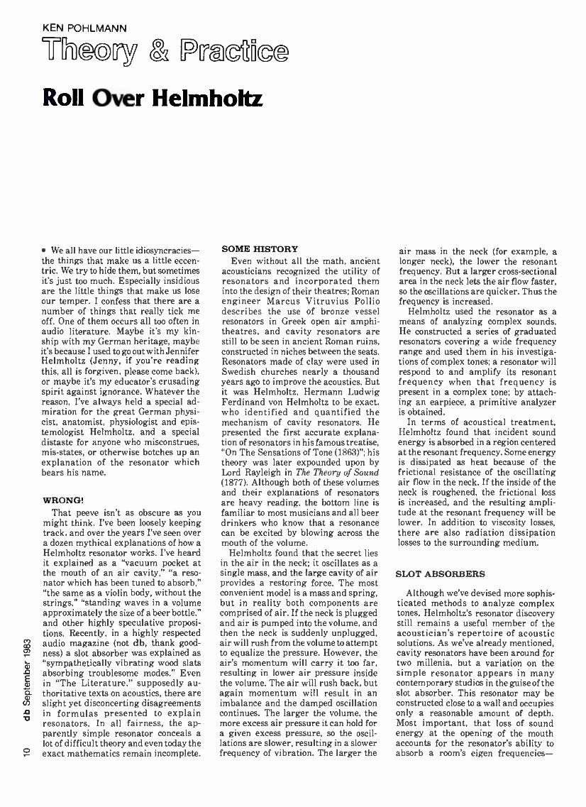
KEN POHLMANN
Roll Over Helmholtz
We all have our little idiosyncracies- the things that make us a little eccen- tric. We try to hide them, but sometimes it's just too much. Especially insidious are the little things that make us lose our temper. I confess that there are a number of things that really tick me off. One of them occurs all too often in audio literature. Maybe it's my kin- ship with my German heritage, maybe it's because I used to go out with Jennifer Helmholtz (Jenny, if you're reading this, all is forgiven, please come back), or maybe it's my educator's crusading spirit against ignorance. Whatever the reason, I've always held a special ad- miration for the great German physi- cist, anatomist, physiologist and epis- temologist Helmholtz, and a special distaste for anyone who misconstrues, mis- states, or otherwise botches up an explanation of the resonator which bears his name.
WRONG! That peeve isn't as obscure as you
might think. I've been loosely keeping track. and over the years I've seen over a dozen mythical explanations of how a Helmholtz resonator works. I've heard it explained as a "vacuum pocket at the mouth of an air cavity," "a reso- nator which has been tuned to absorb," "the same as a violin body, without the strings," "standing waves in a volume approximately the size of a beer bottle," and other highly speculative proposi- tions. Recently, in a highly respected audio magazine (not db, thank good- ness) a slot absorber was explained as "sympathetically vibrating wood slats absorbing troublesome modes." Even in "The Literature," supposedly au- thoritative texts on acoustics, there are slight yet disconcerting disagreements in formulas presented to explain resonators. In all fairness, the ap- parently simple resonator conceals a lot of difficult theory and even today the
° exact mathematics remain incomplete.
SOME HISTORY Even without all the math, ancient
acousticians recognized the utility of resonators and incorporated them into the design of their theatres; Roman engineer Marcus Vitruvius Pollio describes the use of bronze vessel resonators in Greek open air amphi- theatres, and cavity resonators are still to be seen in ancient Roman ruins, constructed in niches between the seats. Resonators made of clay were used in Swedish churches nearly a thousand years ago to improve the acoustics. But it was Helmholtz, Hermann Ludwig Ferdinand von Helmholtz to be exact, who identified and quantified the mechanism of cavity resonators. He presented the first accurate explana- tion of resonators in his famous treatise, "On The Sensations of Tone (1863) "; his theory was later expounded upon by Lord Rayleigh in The Theory of Sound (1877). Although both of these volumes and their explanations of resonators are heavy reading, the bottom line is familiar to most musicians and all beer drinkers who know that a resonance can be excited by blowing across the mouth of the volume.
Helmholtz found that the secret lies in the air in the neck; it oscillates as a single mass, and the large cavity of air provides a restoring force. The most convenient model is a mass and spring, but in reality both components are comprised of air. If the neck is plugged and air is pumped into the volume, and then the neck is suddenly unplugged, air will rush from the volume to attempt to equalize the pressure. However, the air's momentum will carry it too far, resulting in lower air pressure inside the volume. The air will rush back, but again momentum will result in an imbalance and the damped oscillation continues. The larger the volume, the more excess air pressure it can hold for a given excess pressure, so the oscil- lations are slower, resulting in a slower frequency of vibration. The larger the
air mass in the neck (for example, a longer neck), the lower the resonant frequency. But a larger cross -sectional area in the neck lets the air flow faster, so the oscillations are quicker. Thus the frequency is increased.
Helmholtz used the resonator as a means of analyzing complex sounds. He constructed a series of graduated resonators covering a wide frequency range and used them in his investiga- tions of complex tones; a resonator will respond to and amplify its resonant frequency when that frequency is present in a complex tone; by attach- ing an earpiece, a primitive analyzer is obtained.
In terms of acoustical treatment, Helmholtz found that incident sound energy is absorbed in a region centered at the resonant frequency. Some energy is dissipated as heat because of the frictional resistance of the oscillating air flow in the neck. If the inside of the neck is roughened, the frictional loss is increased, and the resulting ampli- tude at the resonant frequency will be lower. In addition to viscosity losses, there are also radiation dissipation losses to the surrounding medium.
SLOT ABSORBERS
Although we've devised more sophis- ticated methods to analyze complex tones, Helmholtz's resonator discovery still remains a useful member of the acoustician's repertoire of acoustic solutions. As we've already mentioned, cavity resonators have been around for two millenia, but a variation on the simple resonator appears in many contemporary studios in the guise of the slot absorber. This resonator may be constructed close to a wall and occupies only a reasonable amount of depth. Most important, that loss of sound energy at the opening of the mouth accounts for the resonator's ability to absorb a room's eigen frequencies-

Studer Re- States
the Art
6n1UDEìi ..,e ,.a,
. . . .
a aa©©
With the new A810, Studer makes a quantum leap forward in audio recorder technology. Quite simply, it re- states the art of analog audio recording.
By combining traditional Swiss craftsmanship with the latest microprocessor control systems, Studer has engineered an audio recorder with unprecedented capabilities. All transport functions are totally micro- processor controlled, and all lour tape speeds (3.75 to 30 ips) are front -panel selectable. The digital readout gives real time indication (+ or - in hrs, min, and sec) at all speeds, including vari- speed. A zero locate and one autolocate position are always at hand.
That's only the beginning. The A810 also provides three "soft keys" which may be user programmed for a variety of operating features. It's your choice. Three more locate positions. Start locate. Pause. Fader start. Tape dump. Remote ready. Time code enable. You can program your A810 for one specialized application, then re- program it later for another use.
There's more. Electronic alignment of audio parameters (bias, level, EQ) is accomplished via digital pad networks. (Trimpots have been eliminated.) After programming alignments into the A81O's memory, you simply push a button to re -align when switching tape formulations.
The A810 also introduces a new generation of audio electronics, with your choice of either transformerless or transformer -balanced in /out cards. Both offer advanced phase compensation circuits for unprecedented phase linearity. The new transport control servo system responds quickly. runs cool, and offers four spooling speeds.
Everything so far is standard. As an option. the A810 offers time -coincident SMPTE code on a center track between stereo audio channels. Separate time code heads ensure audio /code crosstalk rejection of better than 90 dB, while an internal digital delay automatically compensates for the time offset at all speeds. Code and audio always come out together. just like on your 4- track. Except you only pay for 1" tape.
If you'd like computer control of all these functions, simply order the optional serial interface. It's compatible with RS232, RS422, and RS422- modified busses.
More features, standard and optional, are available. We suggest you contact your Studer representative for details. Granted, we've packed a lot into one small package. but ultimately you'll find that the Studer A810 is the most versatile, most practical, most useable audio recorder you can buy.
The Swiss wouldn't have it any other way.
,STUDER 0 TzEI-1...N
Studer Revox America, Inc. 1425 Elm Hill Pike, Nashville, TN 37210 (615) 254 -5651 Offices: Los Angeles (213) 780 -4234 New York (212) 255 -4462 Dallas (214) 760 -8647 Canada: Studer Revox Canada, Ltd.
Circle 18 on Reader Service Card

either with a narrow or wide band characteristic. A number of configura- tions are possible, but the basic design calls for a series of wood slats laid in parallel in a plane, and angled from the rear wall. The approximate fre- quency of resonance is determined by the volume:
f c A
2a V dV where c = velocity of sound.
A = area of slat, d = thickness of slat. V = volume between slat and
wall.
The absorption characteristic may be varied in a number of ways; a sound absorbing blanket placed in the air gap behind the slats dampens the resonant response and broadens its bandwidth. Moreover, there is an improvement in absorption at oblique incidence, espe-
cially as the amount of filling increases to effectively decouple the individual slots. For maximum effect, the porous material should be placed at the front of the gap (next to the slats) where the air particle velocity is at its maximum. Building with non -uniformly spaced and non -uniformly dimensioned slats also broadens the characteristic. Care- ful attention must be paid to the dimen- sioning behind the slats: the phase of the wave reflected from the rear wall,
as it returns to the mouth of the slot, will affect absorption. The air space behind the slats can be partitioned to form smaller volumes with inversely higher resonant frequencies. Slot absorbers are one of the most effective kinds of resonators, and it is perhaps slightly magical to observe the acoustic results in a room tuned with this kind of construction. But far from being magic, some highly interesting theory underlies its operation.
THE HELMHOLTZ RESONATOR A Helmholtz resonator is a simple
type of resonator; it is an enclosed volume with an opening to the outside medium. Specifically, it is a system with one degree of freedom and as such has a characteristic response common to all acoustic, electrical, or mechanical systems with one degree of freedom. In fact, the underlying mathematics is identical for each of these types of systems. Acoustic inertance, com- pliance, and resistance form an ana- log with electrical inductance, capaci- tance, and resistance, and with me- chanical mass, compliance, and re- sistance. For example, we can draw a Helmholtz resonator in terms of either of its acoustic or electrical driven oscillator analogues, as seen in FIGURE 1.
In its acoustic model, the plug of air
in the mouth is the mass element, inter- nal pressure is stiffness or compliance, and radiation dissipation and viscosity provide resistance. Given these ele- ments, appropriate formulas may be derived. We may define the acoustic inertance M of the acoustic element as follows:
M S2
where m = effective mass of the element,
S = area of opening. This leads to the empirical approxi-
mation for the Helmholtz resonator, which is determined by the formula:
M= áó(l +Nfg) S
where po = density of air. / = depth of opening.
Figure 1. The acoustic and electrical analogs of a Helmholtz resonator.
1
411 %/i/.: Mew
i Soun.-. 83381uawMo-.
The control electronics behind the 83 Studio Reference Monitor System Meyer Sound's 833 Studio Reference
Monitor System is standardised for consistent response giving a growing number of pro- fessional engineers and producers more creative control. The C833 controller shown regulates frequency and phase response, and has Meyer's exclusive Speaker Sensew circuitry to prevent driver overload. The 833 handles up to 400W, with power and head- room that lets you feel the full effect of the music - and performs consistently for longer
than previous speaker designs. Effectively linear time response and improved 'coherence'* ensure clear and controllable stereo imaging.
*See our new brochure on the 833.
To see the difference in our speakers, or hear the difference in our system -see us at AES in New York - or contact Meyer Sound. Circle 19 on Reader Service Card
Meyer Sound
Meyer Sound Laboratories Inc. 2194 Edison Avenue, San Leandro, Californio 94577, USA. Telephone: (415) 569 -2866

"I referApollo Master blanks p .. formy rangt critical work:'
Vladimir Mellen Custom Mastering Engineer Columbia Records Mastering Studios. New York City
"I believe they give as quiet a cut as you can get through conven- tional mastering."
"The Apollo has all the pluses mastering engineers look for." \1'c designed into the Apollo lacquer all the na- tures the mastering engineers have been asking for: better flatness. less noise. clean cutting. longer stylus life. better uniformity and consis- tency. Ultimately, the Apollo results it better records.
"Absolutely flat!' All aluminum blanks used for the Apollo are micropolished using a process originally devel- oped liar magnetic computer disks. This multi- step process resurfaces the aluminum blanks and creates a line finish. free from detects and with an improved Ilatness.
"Free of ticks and pops" Our elaborate lacquer manufacturing process insures that all particles and gels which could cause cutting problems are removed. Moreover. the new formulation resists lacquer buildup on the stylus, thus reducing grouse wall scoring and loose debris in the groove, hieb contribute to ticks and pops.
"Least abrasion!' The unique Apollo ti,rmulation reduces the cut- ting friction when contacted by the heated stylus. This results in lower abrasion, thus extending the stylus life. And. of course. the for- mulation tion does not use any abrasive i in the first place.
ingredients
"Very consistent from batch to batch!' The excellent consistency of the Apollo lacquer masters is the result of complete control we have over the critical raw materials and the blending of the formulation. In addition, the extensive process and quality control methods assure the maintenance of tight manufacturing bier antes.
We've Mastered the Master.
APOtO Master Audiodisc.
Capitol Magnetics Products. 5902 Sunset &mle'ard. Hulk wood. C.1 1(125 nW Capitol WpWY PredUen. A divi"n et COOS MCwec. Inc An lights "C"rred
Circle 20 on Reader Service Card

In the same way that electrical capacitance is defined as the charge per unit of applied voltage, the acoustic compliance C of an acoustic element is defined as the volume displacement produced by the application of unit pressure, and may be determined by the formula:
V C=
po c2
where V = volume of enclosure, c = velocity of sound.
The dissipation of energy at the resonator mouth is analogous to elec- trical resistance. Considering the dissipation due to radiation from the mouth, we obtain:
R= Po 011
47rc where w = 2r! The resonant frequency occurs when
the acoustic reactance is equal to zero, determined as follows:
wM- 1 =0 wC
Thus the resonant frequency is equal to:
I w =
MC
Furthermore, the Q of the resonant response of a Helmholtz resonator is theoretically given by:
wM
R
And Helmholtz's equations don't end with slot absorbers and beer bottles: the theory may be applied throughout acoustic design. For example, a loud- speaker in a cabinet may be treated as a Helmholtz resonator with an iner- tance comprised of both the reactance of the enclosing air and the speaker cone mass. The effective compliance is similarly the sum of the stiffness of the enclosed air and the cone suspension. The acoustic resistance is the sum of radiation and viscosity losses, and speaker cone mechanical resistance.
Mathematics and patient explana- tions are all well and good, but so far we've managed to dodge the real issue. The essence of the resonator's opera- tion still remains to be revealed. Con- sider the sleight of hand which has occurred. First we explained that Helmholtz used resonators to appar- ently amplify tones within complex sounds, then we told how resonators apparently soak up tones. Consider the following experiments: Hold a tuning fork over a tube partly filled with water
QUALITY RELIABILITY VERSATILITY
hff ff
The David Hafler Company has earned a reputa- tion for producing state of the art power ampli- fiers at rock bottom prices. The Hafler DH -220 and DH -500 Amplifiers are well known for their sound quality, reliability and value.
Now, there's the P -500! The P -500 is a rugged, full -featured amplifier. It combines the circuit design and MOSFET output devices of the DH -500 with extra professional features; an auto- matic 3 -speed fan, barrier strip, phone plug and XLR connectors, balanced or unbalanced in- puts and gain controls, to name just a few. And like other Hafler products, the P -500 is available in fully or partially assembled form.
For a complete list of features and specifica- tions, write to:
The David Hafler Company Dept. DS, 5910 Crescent Boulevard Pennsauken, New Jersey 08109
IhnOlkOP .. ;. . .o.
ma -...J- `.,J--,... ton/ am non sm
and vary the water level until the distance from the water to the top of the tube equals one quarter the wave- length of the tuning fork's frequency. The sound from the tuning fork will get louder. Is this the kind of absorber to use in studio design? Helmholtz's secret is wildly unique.
THE MAGIC REVEALED The general phenomenon of reso-
nance refers to the excitation of a vibration in a body by a wave from another source. The phenomenon is most obvious when the driving fre- quency equals the natural frequency of vibration of the resonator, as in the case of a tenor shattering a glass. In fact, we are tempted to suppose that a resonator can amplify the flow of sound energy after it has left its source. Unfortunately, neither that nor per- petual motion machines are possible; rather, a resonator may increase the flow of energy that is becoming avail- able as sound, but it can never multiply the flow of sound already present. A resonator can cause a source to emit more sound energy (as in musical instruments) because of the changed phase relationship of the velocity and pressure at the source. Consider the analogous case of a pendulum in motion. If force is applied in phase with the maximum velocity, the energy of the system is increased. Of course, an unfavorable phase relationship would result in decreased system energy. The latter is one of the secrets of the Helm- holtz resonator. The characteristic behavior of a small pressure at the neck producing large mass fluctuations can be exploited to effectively decrease acoustic energy near the resonant frequency.
The geometry of a Helmholtz reso- nator creates that characteristic be- havior because it differs from any other design. An open pipe is a simple resonator, but with a Helmholtz there is a change in the cross section, and the small orifice acts to contain energy in the enclosed volume and create a unique "conductivity," as Rayleigh called it. The conductivity determines the extent of the air which vibrates; the value of conductivity varies with the mechanism acting at the orifice. Con- ductivity depends upon the viscous resistance of the orifice (as when a porous blanket is present) or upon the radiation resistance of the orifice. Thus a Helmholtz resonator design, and the resulting conductivity, de- termines whether it acts as a diffuser or an absorber, or a combination of the two. If there are no viscous or thermal losses, the action consists in storing sound energy in its internal vibration and diffusing incident sound as an out - of -phase point source. This storing up of energy accounts for the decrease in instantaneous sound energy; when the incident sound ceases, resonance ceases,

apture sound at it pu st.
Hold a seashell to your ear and hear nature's pure and natural sound. Compare it to the final sound produced by a Neve. You'll begin to understand why Neve is far and away the most respected name in audio mixing. '[he Neve sound is so pure and natural, one might suspect that nature herself had a hand in the design. Perhaps. Not every engineering achievement can be explained away. [here are mysteries in nature, just as there are mysteries man -made.
Some suggest that Neve's unique Formant\Spectrum Equal- izers account for its unparalleled sound by taking into account the psycho- acoustic properties of voice and music while satisfying the critical demands of balance engineers. Others claim it's superior technical performance, novel circuitry, or high quality components. All agree on one thing: To capture sound at its purest, aspire to Neve. For further information, call us, or write.
Rl PERT NEVE INCORPORATED: Berkshire Industrial Park. Bethel, Connecticut 06801 (203)744- 6230'Iìdes 969638 7533 Sunset Blvd., Ilollywood, (California 90046 (213) 874 -8124 Telex 194942 RUPERT NEVE OF CANAI)%. LLD. represented by: Manta Electronics Group. 204 King St. East, Toronto, Ontario 315A 1.17 Canada
(416) 868 -0513 Telex 06.986766 Sonotechnique, 2585 Bates, Suite 304, Montreal, P.Q.II3ti 1 '.9 Canada (514) 739 -3368 Telex 055 -62171 NEVE ELECTRONICS INTERNATIONAL, LID: Cambridge House. Melbourn, Royston. Iieriiord shire, SG86AU England Phone (0763)60776
RUPERT NEVE Gmbl I: 6100 Darmstadt Bismarckstrasse 114, West German. Phone(06151)81764. Circle 21 on Reader Service Card
CD
and the energy is bled back to the system. Viscous losses are also present, always as air particle friction at the high -velocity orifice or as introduced porous absorbers within the resonator. Increasing the amount of porous material dampens the vibration of the absorber and lessens the selectivity of the resonator. When conductivity is equal to unity, there is an approximate equality between viscosity and dif- fusion losses. A larger conductivity favors diffusion losses and yields a more selective characteristic. Un- fortunately, precise calculations for conductivity are almost impossible for practical applications because of the complexity of the acoustics at the mouth of the resonator. That's why you hire an acoustician instead of buying a calculator.
For demonstration purposes only, we'll attempt a practical design -one full of approximations. Using our new- found conductivity element, we can write the formula describing the natural frequency of a volume resonator having a circular orifice as:
where K V c
f 2a V
= conductivity, = volume of resonator, = velocity of sound.
If we ignore the thickness of the resonator's material (i.e. the orifice has no neck length), the value for k is twice the radius of the cylindrical volume. Let's compare the resonating properties for a simple open end pipe with the closed resonator at a frequency of 440 hertz. A pipe of cross -sectional area of 10 square centimeters would re- quire a length of one fourth the wave- length of 440 hertz, or 18.8 centimeters. If we build a Helmholtz with a closed top and circular orifice of 1.0 centi- meter in diameter, our formula pro- duces a length requirement of 14.4 centimeters. Encouraged by our suc- cess, suppose we design a Helmholtz resonator with a neck 2.0 centimeters long and 1.0 centimeter in diameter. Using a new approximation for con- ductivity,
ar t= irr /2
where r = radius of orifice. = radius of neck,
we find that our 440 hertz resonance is achieved in a resonator only 4.1 centimeters high. More than anything else, that demonstrates the efficiency of the Helmholtz design and its ability to secure low frequencies with a small air volume. Now you know why we can sing a pitch which otherwise requires
a ten foot organ pipe to produce. And can you explain why the resonator in your throat produces bass notes, while the one on your studio wall absorbs them?
The applications of Helmholtz's resonator theory are endless, and so is the complexity of the math, but I hope we've shed light on the basic idea - at least enough illumination for me to give you fair warning. In the future, I
will not tolerate any more ridiculous explanations of Helmholtz resonators. If I catch anyone at it, I'll print their names and addresses. Poor von Helm- holtz has been rolling around in his grave long enough; let the old guy rest in peace.
I'm glad we settled that. Now I want to speak with all you guys who put those plastic things in your shirt pockets and cram them with mechanical pencils and Bic pens. Do you have any idea how dumb that looks? You've given engi- neers an image problem that they'll never live down. I mean, it really ticks me off....
REFERENCES Olson, H. F., Music, Physics and Engi-
neering, Dover Publications. 1967. Richardson, L. R., Technical Aspects
of Sound, Elsevier Publishing, 1953. Stewart. G. W.. Introductory Acoustics,
Van Nostrand, 1940.
It speaks for itself.
We thought about hiring an expensive superstar to extoll the virtues of the famous Orban 622B Parametric EQ. After all, there are 622B's backing up superstars worldwide in recording studios, arena shows, broadcast facilities... you name it! But we decided not to. Because ultimately, the Orban 622B speaks for itself -it's the most widely used, popular professional Parametric in the world. The 622B combines full, four -band Parametric equalization with tunable notch filtering to offer extraordinary versatility and control. Our "constant -Q" design provides -40dB attenuation while allowing gentle, musically -useful broadband EQ too. This makes the 622B ideal for critical sound reinforcement chores as well as studio production work. Call your local Orban dealer for further information.
or bon Orban Associates Inc. 645 Bryant St. San Francisco, CA 94107 (415) 957 -1067 TLX: 17 -1480
Circle 22 on Reader Service Card

6.1 6.11.1.1
CEE OEM MID MID
1
IK
.15 15
Co, LEO LOW LOW
1.11 NM NM Du
CI-10
ib PF1E
Ai STERLO
ECHO
1.11 O - PRE
AV: SILRE
ECHO
And a now
message on
Yamahas new RM1608 recording
mixer.
R PHL
MIN il PHL - ,,111 - PHL
' i AN. .7I s , ... . ...., IAPE 101N,,,, - IAPE
: IM ,: 111111. - ,` MIL LS P01,1 1'0 r'..,N1 fo - PLiM
Le vEL LEVEL
REO STEREO STEREO
LAPE
: LEVEL
STEREO
011.. CH ON SOW CH ON - SOLO CH ON SOLO IfireiN
0 -0 5
10 10
15 15
20 20
- 5
o -0 -5
10 10
15 -111 15
20 20 __ ME 25 ..-111111f 25 - 25
-30 35
-30 -35
30
35 -35
IO
PGM 7
151,,
0- 0-
iN1
I o
CON T L ROOM F6td1 8
SOLO
STEREO
O
5
15
2o
-25 -
MIL LEVEL
TALK BACK
- FUNCTION -
3,
MULTI
2TRK
MXD
e 10
IN O
OUT 0 2
IN 0 0
,

RM1608 SPECIFICATIONS
TOTAL HARMONIC DISTORTION (T.H.D.) Less than 0.1% at +4dB *output, 20Hz to 20kHz (all Faders and controls at nominal)
HUM & NOISE (20Hz to 20kHz) Rs = 150 ohms (INPUT GAIN " - -60 ")
- 128dB Equivalent Input Noise (E.I.N.) - 95dB residual output noise: all Faders down.
(84dB S /N) PGM Master volume control at maximum and all CH PGM assign switches off. (68dB S /N) PGM Master volume control at maximum and one CH Fader at nominal level. (77dB S /N) STEREO Master Fader at maximum and all CH STEREO level controls at minimum level. (68dB S /N) STEREO Master Fader at maximum and one CH STEREO level control at nominal level. (70dB S /N) ECHO SEND volume at maximum and all CH ECHO volumes at minimum level. (65dB S /N) ECHO SEND volume at maximum and one CH ECHO volume at nominal level.
- 80dB - 64dB - 73dB - 64dB - 80dB - 75dB
CROSSTALK - 70db at 1kHz: adjacent Input. - 70db at 1kHz: Input to Output.
MAXIMUM VOLTAGE GAIN (INPUT GAIN "- 60" ) PGM 74dB: MIC IN to PGM OUT.
24dB: TAPE IN to PGM OUT. 34dB: ECHO RETURN to PGM OUT 14dB: PGM SUB IN to PGM OUT
STEREO 74dB: MIC IN to STEREO OUT. 24dB: TAPE IN to STEREO OUT 34dB: ECHO RETURN to STEREO OUT.
CHANNEL EQUALIZATION ± 15 dB maximum HIGH: from 2k to 20kHz PEAKING. MID: from 0.35k to 5kHz PEAKING. LOW: from 50 to 700 Hz PEAKING.
HIGH PASS FILTER - 12dB/octave cut off below 80Hz.
OSCILLATOR Switchable sine wave 100Hz,1kHz,10Hz
PHANTOM POWER 48V DC is applied to XLR type connector's 2 pin and 3 pin for powering condenser microphone. DIMENSION (W x H x D) 37 -1/2" x 11" x 30 -1/4" (953 mm x 279.6 mm x 769 mm)
Hum and Noise are measured with a - 6dB /octave filter at 12.47kHz; equivalent to a 20 kH: filter with infinite dB. octave attenuation. 'OdB is referenced to 0.775V RMS. Sensitivit is the lowest level that will produce an output of - 10,113 1245m \'Lor the nominal output level when the unit is set to maximum gain.
All specifications subject ro change without notice.
ECHO C/R
STUDIO
70dB: MIC IN to ECHO SEND. 74dB: MIC IN to C/R OUT 24dB: 2 TRK IN to C/R OUT. 74dB: MIC IN to STUDIO OUT. 24dB: 2 TRK IN to STUDIO OUT.
The specs speak for themselves. But they can't tell you how natural, logical and easy the RM1608 is to work. All the controls and switches are logically arranged to help you get the job done quickly and accurately.
And in the tradition of Yamaha's sound reinforcement mixers, the RM1608 sets new standards of reliability as well as ease of operation. For complete information, write: Yamaha International Corporation, P.O. Box 6600, Buena Park, CA 90622. In Canada,Yamaha Canada Music Ltd., 135 Milner Ave., Scarborough, Ont. MIS 3R1.
*YAMAHA Circle 23 on Reader Service Card

LEN FELDMAN
Sound Mr VHS Plays Audio `Catch -Up' With Beta
A few months ago in this column I
described a method of two- channel audio recording that was developed by Sony Corporation as a high -fidelity audio system for use with their Beta - format video recorders. The system successfully nestles a pair of frequency - modulated carriers between the chro- minance and luminance video signals. applying these extra carriers to the magnetic tape medium via the same fast -spinning video heads which lay down the video signals. Since describ- ing that system, I have had an oppor- tunity to test the first Beta HiFi VCRs and can attest to the fact that per- formance equals or exceeds that ob- tained using the very finest analog, reel -to -reel professional tape decks without added noise reduction. Specif- ically, wow- and -flutter is reduced to a negligible and inaudible 0.005 percent, distortion is of the order of 0.3 percent
and frequency response is ruler -flat from 20 Hz to 20,000 Hz. With a system such as this, one wonders just how much of an advantage true digital recording offers when you consider that the cost of a Beta HiFi VCR is far less than even a minimum -featured PCM processor plus a conventional VCR which would have to be added to it as a tape transport.
Sony's aim (and the aim of other manufacturers licensed to produce Beta format VCRs) in introducing Beta HiFi was to capture a larger share of the VCR market which, over the years since the introduction of the original Betamax VCRs, has drifted more and more towards the VHS type of VCR. VHS recorders were developed a year after Beta by Victor Company of Japan (known here as JVC), and outsell Beta format machines by a factor of around 7 to 3 in the United States. Since the
audio quality of conventional Beta machines and currently available VHS machines is inferior to that of the lowest quality home audio cassette recorder, the developers of Beta HiFi felt that by offering improved audio second only to digital recording, they could significantly increase their market share. Furthermore, because of the specific baseband frequency assign- ments used in VHS recorders, sup- porters of the Beta system were con- vinced that the VHS folks would simply not be able to "squeeze in" an extra pair of FM carriers with the video signals, using the video heads, because of the particular arrangement of the video signal frequencies themselves in the VHS format. If they tried it, said the Beta people, they would have to degrade picture quality or make the new VHS format incompatible with older machines and tapes.
UNCOMPROMISING WIRELESS MICROPHONES Finally, you can choose a wireless mic to fit the appli- cation. The Telex WHM -300, the electret wireless transmitter mic for uncompromising speech clarity. Or a Telex WHM -400 dynamic wire- less transmitting mic for vocal entertain- ment with rich, full bodied audio quality. ;
Both elegantly tapered and without trailing antenna wires. Or select the miniature electret WLM -100 k '
T\t7 lavalier mic (or any standard dynamic mic) with our belt - pack transmitter.
Combined with the superb Telex dual diversity* FM receiver, you'll have a wireless system that is as good as any hard wired mic, and at a reasonable price. Write us today for full details.
'U.S. Patent No 4293955 Other patents applied tor.
r
,:C
Quality products for the Audio Professional
TELEX TELEX COMMUNICATIONS, INC.
u A.e So MN 55150 U S A _, alii Le &r/apart. .711 Centre Allures Paris Nord 93153 Le Blanc Mesrul F.ar.
Circle 24 on Reader Service Card
(D

RECORDING
VIDEO
ria - ch, d, :, cowl
- L
1 ft NN
I
1- AMP J
PLAYBACK
MI
fM uuWUlelu,
I 7 MNe
MH[
I. mad audio head
Tapo
Pelee Ho
bead
f_ M.....m. tI
Voice head
MIN En
_ i
NR
AMP
AMP
L
Vidc,. Mad
Audio hued
Figure 1. Separate audio heads are added to the spinning head -drum in JVC's newly developed VHS HiFi System of stereo audio recording for video. Fixed stereo audio head is retained for compatibility.
Proven Performers. Improved.
1365 N. McCan St. Anaheim, CA 92806 714.632.8500 800.854.7181 TWX 910.591.1191
Circle 25 on Reader Service Card
VHS DOES IT TOO -BUT SOMEWHAT DIFFERENTLY
The history of home video recording, as you can see, has been one case of "catch -up" after another. In 1976, just a year after Sony Corporation intro- duced their first Betamax home video cassette recorder, JVC introduced the first VHS machine which permitted two hours of continuous video record- ing as opposed to Beta's one -hour recording capability. It wasn't too long after that the Beta camp introduced the Beta II format, which permitted a total of three hours of recording. The VHS adherents soon followed through with their LP speed (four hours of record- ing). after which Beta format machines introduced Beta III recording, with its five -hour recording capability. This was followed by the VHS introduction of the EP (or SLP speed), which offered six hours of recording and, when T -160 tapes were introduced, even eight hours of uninterrupted recording and playback.
As everyone expected, JVC's re- search department wasn't ready to concede defeat. And at the recently con- cluded Consumer Electronic Show in Chicago they revealed the details of their own VHS HiFi system which had been demonstrated even earlier in Tokyo. Having listened to the new system, and watched video picture re- production accompanying the sound, I can attest that VHS HiFi not only
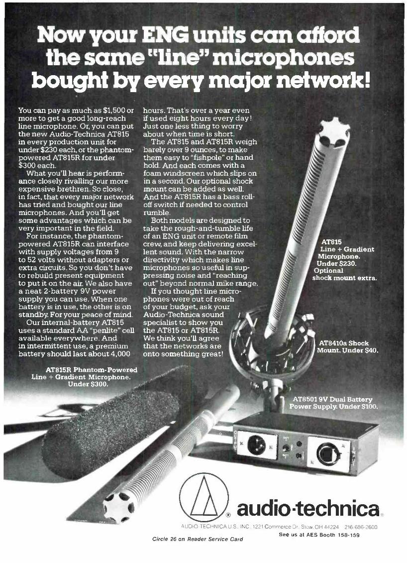
Now your ENG units can afford the same "line" microphones
bought by every major network! You can pay as much as $1,500 or more to get a good long -reach line microphone. Or, you can put the new Audio -Technica AT815 in every production unit for under $230 each, or the phantom - powered AT815R for under $300 each.
What you'll hear is perform- ance closely rivalling our more expensive brethren. So close, in fact, that every major network has tried and bought our line microphones. And you'll get some advantages which can be very important in the field.
For instance, the phantom - powered AT815R can interface with supply voltages from 9 to 52 volts without adapters or extra circuits. So you don't have to rebuild present equipment to put it on the air. We also have a neat 2- battery 9V power supply you can use. When one battery is in use, the other is on standby. For your peace of mind.
Our internal- battery AT815 uses a standard AA "penlite" cell available everywhere. And in intermittent use, a premium battery should last about 4,000
AT815R Phantom - Powered Line + Gradient Microphone.
Under $300.
hours. That's over a year even if used eight hours every day! Just one less thing to worry about when time is short.
The AT815 and AT815R weigh barely over 9 ounces, to make them easy to "fishpole" or hand hold. And each comes with a foam windscreen which slips on in a second. Our optional shock mount can be added as well. And the AT815R has a bass roll - off switch if needed to control rumble.
Both models are designed to take the rough- and -tumble life of an ENG unit or remote film crew, and keep delivering excel- lent sound. With the narrow directivity which makes line microphones so useful in sup- pressing noise and "reaching out" beyond normal mike range.
If you thought line micro- phones were out of reach of your budget, ask your Audio -Technica sound /
specialist to show you the AT815 or AT815R. We think you'll agree that the networks are onto something great!
AT815 Line + Gradient
Microphone. Under S230.
Optional shock mount extra.
AT8410a Shock Mount. Under $40.
AT8501 9V Dual Battery Power Supply. Under $100.
audiotechnica. AUDIO -TECHNICA U S.. INC . 1221 Commerce Dr Stow OH 34224 216 686-2600
See us at AES Booth 158 -159 Circle 26 on Reader Service Card

Ñ
VIDEO SIGNAL
AUDIO SIGNAL - 4.14
SURFACE LAYER RECORDED VIDEO
DEEP LAVER. RECORDED AUDIO
\\ \ -
TAPE MAGNETIC MEDIUM
TAPE BASE
Figure 2. FM audio signals are recorded to full depth of the tape's magnetic medium and video signals are then recorded on the surface layer.
works magnificently, but that it does not noticeably degrade picture quality in any way.
EXTRA HEADS AND DEPTH -MULTIPLEX RECORDING
VHS HiFi is based upon a recording process that J VC calls Depth Multiplex
Recording. It uses a pair of independent rotary FM -audio heads mounted on the head drum containing the video tape heads (two or four, depending upon the VCR). Thus, for a VCR having four video heads, the total number of heads around the perimeter of the rotating drum would be six, as illustrated in FIGURE 1. As for the Depth Multiplex
IN STOCK! Saki heads are the finest in the industry. Every head is dynamically tested and unconditionally
guaranteed to meet or
exceed 3M specifications.
SAKI SAKI MAGNETICS, INC. ® A CALIFORNIA CORPORATION
8650 Hayden Place, Culver City, CA 90230 213 / 559 -6704 (TWX- 910 -328 -6100)
See us at AES Booth 105
Circle 27 on Reader Service Card
principle. first the two -channel audio signal is recorded deeply into the tape's magnetic coating in the form of fre- quency- modulated signals. The carrier frequencies for these audio channels are 1.3 MHz and 1.7 MHz. Then the video signal, consisting of the luminance signal and the down- converted chromi- nance signal, is recorded on top of the audio signal in a shallower layer, as illustrated in FIGURE 2. The video signal spectrum is identical to that of the regular VHS recording system, with the FM luminance (brightness) signal having a deviation or FM spread of from 3.4 to 4.4 MHz, and the chromi- nance (color) signal modulated on a carrier having its center frequency at 629 kHz.
During playback, the FM audio signals in the deep layer of the magnetic tape medium are read through the video information recorded on the sur- face layer. Frequency distribution for the chrominance and luminance sig- nals in a conventional VHS recorder is illustrated in the upper diagram of FIGURE 3. In the lower diagram. the frequency allocation for the extra two audio signals is depicted separately, and it is clear that the video output signal frequency spectrum remains exactly as it was in a conventional VHS VCR. As a result, video recordings re- main perfectly compatible between VHS HiFi and conventional VHS machines. Furthermore, as you can see from FIGURE 1, a fixed audio head is retained in the new VHS HiFi set -up so that older tapes can be played on the yet -to -be produced VHS HiFi ma- chines. Conversely, recordings made on a future VHS HiFi VCR would in- clude an audio track recorded by means of this extra stationary head so that audio (either mono or stereophonic if a split, stationary head were used) would be available if the tape is played on an older, conventional VHS machine.
The presence of the third, stationary audio head lends itself to other applica- tions. For example, in future tapes of foreign language motion pictures, the pair of VHS HiFi heads on the spinning drum might be used to record the motion picture sound tracks in stereo, while the "low fi" stationary head could be used to dub a mono or stereo audio track in the local language of the country in which the tape is distributed.
In VHS HiFi, the video heads have azimuth angles of tilt of +6 degrees and -6 degrees, while the angles of tilt for the extra pair of audio heads are +30 degrees and -30 degrees. Because of this difference, crosstalk between audio and video signals and that be- tween audio signals on adjacent tracks are effectively suppressed.
The technical specifications for VHS HiFi read very much like those previ- ously announced for Beta HiFi. Specif- ically, frequency response is flat from

Protect your investment with a cannon.
An audio coin ureter oy ally other name is simply not an ITT Cannon audio connector Which is precisely why so many audio engineers con- tinue to specify Cannon connectors for use with their audio equipment.
The XLR, the new XLB and XLA series are small, rugged, quick- disconnect connectors designed for use in audio /video and other low level circuit applications where reliability, quiet opera- tion, elimination of mechanical interference and ease of use are necessary Four different plug styles are available.
The EP connector is ideally suited to applications where extreme ruggedness and versatility are required. The new AP connector is a
Audio Connectors from Cannon
popular choice for heavy duty audio applications and is inter- changeable and intermateable with the EP series. Both the EP and AP series may be used where as few as 3, or as many as 18, contacts are required.
The AP LNE and AX LNE are specifically designed to handle the special needs of mains and other power supply applications.
For more information, please contact International Products Marketing Manager, ITT Cannon, a division of International Telephone and Telegraph Corporation, 10550 Talbert Avenue, Fountain Valley, CA 92708, (714) g64 -7400
CANNON ITT The Global Connection
Circle 28 on Reader Service Card

VHS VIDEO SIGNAL SPECTRUM
Frepw,.y Mix)
3.4 44
VHS Hi -Fi VIDEO HEAD OUTPUT SIGNAL SPECTRUM
C r
0 1 2 Frequency IMHZI
AUDIO HEAD OUTPUT SIGNAL SPECTRUM
3A 44
3 4 Frequency IMHt)
Figure 3. Video signal spectrum in VHS HiFi remains unaltered. Audio head output signals in the form of two FM carriers are added to standard VHS video signal spectrum as shown in the lower diagram.
PERFORMANCE QUALITY VALUE
RENKUS -HEINZ PROFESSIONAL
AUDIO COMPONENTS
í
EVERYTHING IN
DRIVERS
HORNS
WOOFERS
NETWORKS
SPEAKER SYSTEMS
FREE: Send for the Renkus -Heinz Catalog describing the complete professional audio equipment line, and the
ASK YOUR DEALER FOR A DEMO name of the dealer in 0 your area.
RENKUS- HEINZ, INC. 17851 AB Sky Park Circle Irvine CA 92714 (714) 540 -3154
Circle 29 on Reader Service Card
20 Hz to 20.000 Hz; dynamic range is better than 80 dB; harmonic distortion is less than 0.3 percent; wow- and -flutter is a negligible 0.005 percent or less, and channel separation is greater than 60 dB. Frequency modulation im- proves the dynamic range of the audio signals to achieve more than 60 dB of dynamic range. To further expand this range to the claimed 80 dB. VHS HiFi utilizes a noise reduction system which, in their words, "is the most suitable for FM recording and playback." Specific details concerning this extra noise reduction system were not dis- closed.
AVAILABILITY The demonstration of VHS HiFi that
we heard in Chicago was so effective that we wondered why JVC was not ready to quote a delivery date or even a price for the first models of VCRs incorporating this superior stereo audio system. After repeated question- ing we learned that there were still some aspects of the new system that required standardization among the major producers of VHS VCRs. Upon further questioning, we learned that the VHS HiFi type machine demon- strated by Matsushita Electric (Pana- sonic brand) in Japan some months ago, while basically compatible with the machine demonstrated by JVC, was not totally compatible in every single detail.
While we could not determine just what areas of incompatibility re- mained. we were assured that what- ever the differences, they were minor and would soon be resolved. If the delay leads to total compatibility (rather than a split among the producers of VHS machines), that will certainly be worthwhile. What we don't need, either from the point of view of software or hardware, are three incompatible systems.
PROFESSIONAL APPLICATIONS Many industry pundits have pre-
dicted that when consumer video re- corders adopt the recently agreed to 8 millimeter tape format which was described in these pages a couple of months ago. professional users of video equipment may well "move down" to half -inch tape formats. finally aban- doning the U -Matic % -inch format whose technical capabilities have re- mained fairly static over the last few years. Now that VHS VCRs appear ready to upgrade the quality of their audio channels, it is clear that elec- tronic news gathering teams and others involved in in- the -field audio /video recording will have a choice as to which system they want to use. This becomes especially important as we come closer to the introduction of high -quality stereophonic sound on TV which, by all accounts, should finally be with us sometime in 1984.

We've raised the speed limit. Our new DP -80 high -speed duplicating system runs at an amazing 480 i.p.s.
That's faster than any other duplication system. Twice as fast. Designed especially for large production runs of music cassette tapes, the new
DP -80 system means higher product quality because the masters can now be prepared at 7.5 i.p.s. That's twice as fast as any other system too.
Hear how the Otani DP -80 "Faster Masters" system can make better sounding cassettes, and bigger profits for you.
Make tracks - fast -to booth 442 at the 74th Audio Engineering Society Convention at the New York Hilton, October 9 -12.
Otani Industrial Products Division, 2 Davis Drive, Belmont, CA 94002, Telephone: (415) 592 -8311, TELEX: 910 -376 -4890.
0I0©ß Technology You Can Trust
Audio Tape Duplicators & Video Tape Loaders Corporation. 194CI
Circle 30 on Reader Service Card

20 reasons why the QSC Model 1400 should cost more. And why it doesn't.
Until now, designing a premium professional ampli- fier was seemingly a set pro- cedure. All that was needed to introduce a new product was a new feature, a hot new com- ponent, more power, or per- haps some complicated circuit gimmickry designed to impress others with "technical superiority."
The results were almost always the same: very little improvement in real -world
performance or reliability accompanied by a hefty increase in price.
But we at QSC decided that you deserved more than that.
So we went back to square one, taking a hard look at professional amplifier design and construction basics. We found a lot of room for improvement. Time and tech- nology had changed things. Approaches that had been taken for granted for years were
out of date. They needed re- evaluation... and a breath of fresh air.
With that in mind, we designed Series One. A line of amps that include a host of features (including many advancements gained from our revolutionary Series Three amplifiers) and the finest in high quality/high perfor- mance components. We examined existing construc- tion and assembly methods and re- engineered them to be much more efficient.
The result is almost unbeliev- able.Take the Model 1400 for example. It's equal to or better than any premium power amp on the market in terms of features, perfor- mance, reliability, or quality of components. In terms of price,
it could command a com- parable price tag. But the same rethinking that made the Model 1400 technologically superior also made it less expensive. How much less? Like we said, it's almost unbelievable: only $698.007
In all modesty, we feel that we've created a whole new price -class of premium power amplifiers. A look at the fea- tures we've outlined here will give you some indication of the technology that makes the QSC Model 1400 uniquely superior. Ironically, many are the same features that make it so affordable.
To find out more about the 1400, see your QSC Audio Products dealer. After all, can you afford not to? 'Manufacturer's suggested retail price.
'"rigiii0e
'"+ye -..no mad 11.11

. Power A hefty 200 watts per channel @
8 ohms, 300 watts per channel @
4 ohms, 20- 20kHz, both channels driven.
. Lightweight, Compact Size Advanced design reduces weight to a mere 27 lbs.
. Flow- Through Cooling High -turbulence heatsink thermally coupled to faceplate dramatically reducesweight.Two -speed fan with back -to -front airflow also helps keep rack cool.
. Case -Grounded Output Transistors Provide a 25% improvement in
thermal transfer increasing reliabil- ity through reduction of thermal cycling fatigue and insulation breakdown.
EMIUM COMPONENTS Large SOA, High Speed, Mesa Output ltansistors Renowned for their ruggedness and audiophile sound.
6.5532 Op-Amp Front End High speed, low- noise, and low - distortion op -amp designed explicitly for high -performance audio.
7. High -Density, Low ESR Filter Capacitors The very latest in advanced foil technology, reduces size and weight while improving performance.
8. FR -4 Fiberglass PCB's High quality circuit boards.
9. Single Piece 14 -Gauge Steel Chassis with Integral Rack Mounts Thicker than normal for extra strength, no welds to crack or screws to loosen.
10. Full Complementary Output Circuit For optimum performance and power.
11. Independent DC and Sub -Audio Speaker Protection Circuit design inherently protects speaker from DC or sub -audio
surges due to output failure. Acts independently on each channel.
12. Dual Power Supplies Split power transformer with separate rectifiers and filters. Pro- vides better channel separation and improved reliability.
13. Patented Output Averaging Short- Circuit Protection Provides superior short circuit protection without the audio degra- dation found in VI limiting.
14. Thumplesslhrn- On,TUm -Off Input muting relay provides turn-on delay and instant turn -off to pro- tect sensitive drivers and speakers.
15. Active Balanced Inputs For superior audio performance while reducing cable- induced hum.
COMPREHENSIVE INTERFACE PANEL 16. Octal Input Socket
Accepts active and passive input modules such as comp /limiters, crossovers, and transformers.
17. y," RTS, XLR, and Barrier Inputs No need for adapters.
18. Mono -Bridging and Input Programming Switches Maximum flexibility without jumpers or patch cords.
19. Optional 70 -Volt Output ltansformers Mount right on the back for use in
distributed systems. 20.2 Years Parts and
Labor Warranty A quality product backed by an extended warranty.
QSC Audio Products 1926 Placentia Avenue Costa Mesa, CA 92627
Sc At
GOUDA SF MARKETING. INC.. 312 Belem Hudon. Montreal, Quebec. Canada HAN IA INTERNATIONAL: E AND E INSTRUMENTS INTERNATIONAL INC.. 23011 Moulton FÒrlmay Bulking F7 t oau,
Wnte Nor aetads and speafrcafrons on These and other products
":f tfPB1PIRRMtit
Circle 31 on Reader Service Card

co
BARRY BLESSER
Re- sampling the Re- sampling Idea
Last month we introduced the idea of building a digital re- sampling system to allow us to convert digital audio from one sampling frequency to an- other. This is important because, for the near future, there will be two or more "standard " sampling frequencies. It is also important for other kinds of signal processing that we will discuss later.
When we developed the idea in the previous article, we presented the
notion of creating, or recreating, the audio signal in between two discrete samples. These created audio samples were to be the new samples when sampled with a new sampling fre- quency. The notion of using an inter- polator for this process is accurate but it prevents us from considering the problem from the more classical view- point. In this article, we will redevelop the concept from the classical filtering view.
We again start the discussion with an audio signal that has been sampled. This is shown in FIGURE 1. These samples are the only information ex- tracted from the incoming signal. Because we assume the bandlimiting restriction of the Nyquist frequency, we know that the original signal could be recovered exactly by a simple opera- tion of low- passing. In the first step of changing the sampling rate, we take these samples and place intermediate
Looking for a Distortion Analyser?
Check the little guy on the right...
1700B
f I 1+tetry de -' 22: 1*. 1 ;
339A 3501
the highest performance, most featured and easiest to use audio distortion and noise measurement system in the industry. (and at the lowest price)
amber Amber Electro Design Ltd. 4810 Jean Talon West Montreal Canada H4P 2N5 Telephone (514) 735 4105
Sound Hewlett Amber Technology Packard 3501 1700B 339A
Automatic Set Level YES YES YES
Automatic Null YES YES YES
IMD: SMPTE DIN CCIF IHF Frequency Range
YES* NO 7kHzfixed
NO NO -
YES* YES* 2kHz- 100kHz
Quantity of Filters 2 3 4 Filters user changeable NO NO YES Differential Input YES NO Option Continuous frequency tuning NO NO YES Calibrated output attenuator NO YES YES Input Monitor YES NO YES Selective voltmeter mode NO NO YES True mis meter NO YES YES
Battery operation NO NO Option Options field installable NO NO YES Residual distortion 1kHz
100kHz <0.002% <0.1%
<0.0018% <0.032%
<0.0008% <0.006%
Residual noise (80kHz BW) <8pV <8µV <2p.V Maximum output 3V 6V 12V Minimum input THD mode lOOmV 30mV 30mV Auto -null time <6 secs not spec <2 secs
Voltmeter sensitivity (F.S.) extended mode
3mV / -50dBm 30µV / -90dBm
lmV / -60dBm NONE
1mV / -60dBm 11.i.V /- 120dBm
Size (cubic feet) 1.0 1.0 0.4 Weight (pounds) 16 18 12.5 Ptice
with IMD ( *option) $2650 $3625
$2450 - $2100 $2800
Circle 32 on Reader Service Card

KEEP YOUR RECORDING
STUDIO COMPETITIVE
INAN INDUSTRY WITH
MORE THAN 33 REVOLUTIONS
PER MINUTE. Find out how, thanks to Sony /MCI, at the Audio Engineering
Show, Booths 225, 226,733 -740, and Suite 529.
\\MOr ® SONY A division of Sony Corporation of America. Professional Audio Products.
Sony Communications Products Company. Sony Drive. Park Ridge. Vex Jersey 07656_ CO 1953 Sony Corp. of America. Sony is a registered trademark of the Som Corp.
Circle 33 on Reader Service Card
samples in between the actual samples. The extra set of samples are all with a value of O. FIGURE 2 shows the digital samples where the odd sample numbers are taken from the real data of FIGURE 1
and the even samples are "artificial," with a value of O. By this simple opera- tion, we have increased the sampling frequency by a factor of 2. There are twice as many samples in the new signal of FIGURE 2 as there were in FIGURE 1.
You might object to this silly way of increasing the sampling frequency because these new zero samples do not really exist. The act of adding them here is just a conceptual way of under- standing the first step in the process of determining the true value of new
A AI t
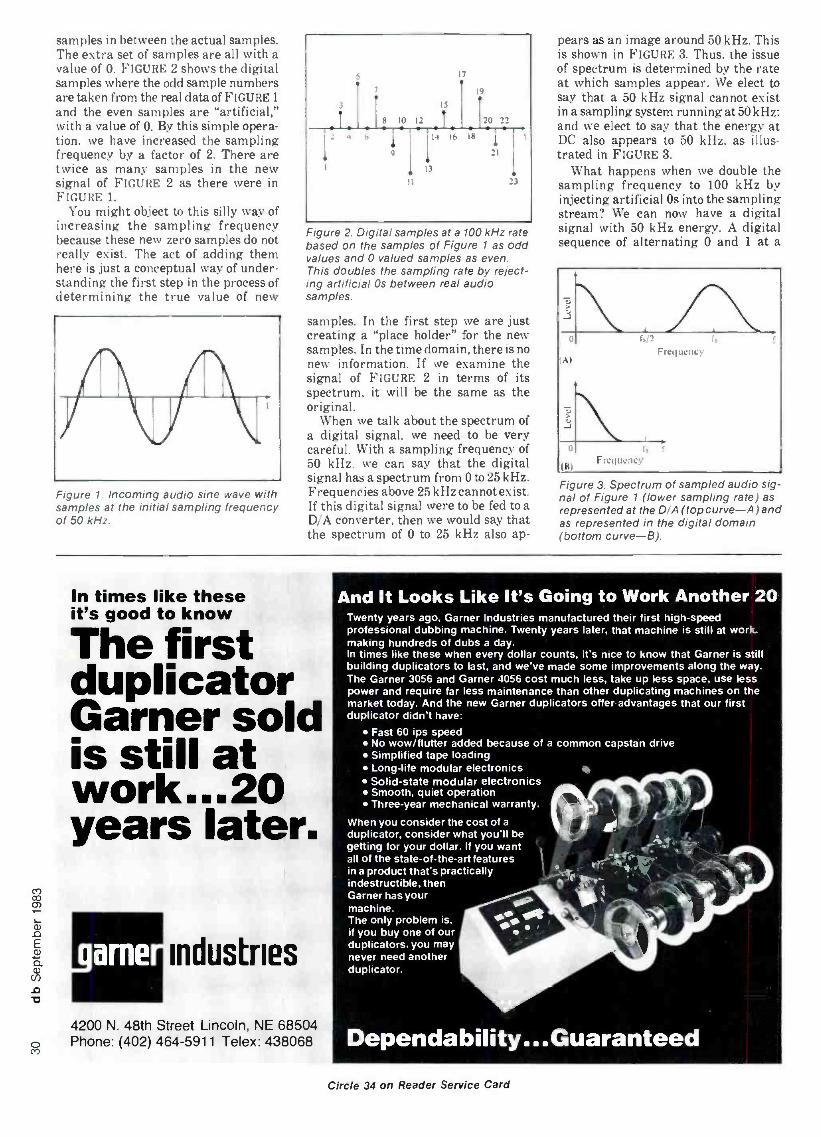
Figure 1. Incoming audio sine wave with samples at the initial sampling frequency of 50 kHz.
Figure 2. Digital samples at a 100 kHz rate based on the samples of Figure 1 as odd values and 0 valued samples as even. This doubles the sampling rate by reject- ing artificial Os between real audio samples.
samples. In the first step we are just creating a "place holder" for the new samples. In the time domain, there is no new information. If we examine the signal of FIGURE 2 in terms of its spectrum, it will be the same as the original.
When we talk about the spectrum of a digital signal, we need to be very careful. With a sampling frequency of 50 kHz, we can say that the digital signal has a spectrum from 0 to 25 kHz. Frequencies above 25 kHz cannot exist. If this digital signal were to be fed to a D/A converter, then we would say that the spectrum of 0 to 25 kHz also ap-
pears as an image around 50 kHz. This is shown in FIGURE 3. Thus, the issue of spectrum is determined by the rate at which samples appear. We elect to say that a 50 kHz signal cannot exist in a sampling system running at 50 kHz; and we elect to say that the energy at DC also appears to 50 kHz, as illus- trated in FIGURE 3.
What happens when we double the sampling frequency to 100 kHz by injecting artificial Os into the sampling stream? We can now have a digital signal with 50 kHz energy. A digital sequence of alternating 0 and 1 at a
r,i' Frequency
f, Frequency
Figure 3. Spectrum of sampled audio sig- nal of Figure 1 (lower sampling rate) as represented at the D/A (top curve -A) and as represented in the digital domain (bottom curve-B).
In times like these it's good to know
The first duplicator Garner sold is still at work...20 years later.
4200 N. 48th Street Lincoln, NE 68504 Phone: (402) 464 -5911 Telex: 438068
And It Looks Like It's Going to Work Another 20 Twenty years ago. Garner Industries manufactured their first high -speed professional dubbing machine. Twenty years later, that machine is still at work making hundreds of dubs a day. In times like these when every dollar counts, it's nice to know that Garner is still building duplicators to last, and we've made some improvements along the way. The Garner 3056 and Garner 4056 cost much less, take up less space, use less power and require far less maintenance than other duplicating machines on the market today. And the new Garner duplicators offer advantages that our first duplicator didn't have:
Fast 60 ips speed No wow /flutter added because of a common capstan drive Simplified tape loading Long -life modular electronics Solid -state modular electronics Smooth, quiet operation Three -year mechanical warranty.
When you consider the cost of a
duplicator, consider what you'll be getting for your dollar. If you want all of the state -of- the -art features in a product that's practically indestructible, then Garner has your machine. The only problem is. if you buy one of our duplicators, you may never need another duplicator.
Dependability... Guaranteed
Circle 34 on Reader Service Card

EVM "' Pro -Line Speakers As a working musician or sound -pro, you con- stantly work to improve and refine your perform- ance. And we at EV know that today's performance demands a wider dynamic range and clean, clear sound. It requires higher instrument or monitor levels on stage and more punch out front. But raising your per- formance stand- ards has been expensive, until now.
That's why we designed the EVM PRO-LINE Series of extra heavy -duty sound reinforcement loudspeakers. The 15" and 18" models can handle 400 con- tinuous watts of "real world" power (not just laboratory sine waves) and an incredible 1600 watts of peak music power. The 12" models will take 300 watts continuous and 1200 watts peak under the same grueling power tests.
They're the newest genera-
tion of maximum efficiency, low -frequency speak- ers designed for cost effective, high -level perfor- mance. The EVM PRO -LINE can give you the extra punch you need with freedom from fear of failure - even when pushed to their limits.
All of this power handling capacity conies with the same EVM efficiency and reliability as our industry standard EVM Series 11 music speakers.
Couple that with EVM's 5 -year loud - speaker guarantee, and our fast, efficient repair service, and you won't find a bet- ter high -powered va- lue than the EVM PRO -LINE Series.
So raise your sound standards. See your EVM dealer or write for more information
to: Greg Hockman, Director of Marketing, Music Products, Electro- Voice, Inc., 600 Cecil Street, Buchanan, N1I 49107.
Electrol/oice SOUND IN ACTION
a quItün company
Circle 35 on Reader Service Card
Updated Recording Studio Handbook
A must for every working professional... student...
audio enthusiast
Features latest state -of -the art technology of creative sound recording.
21 Fact -Filled Chapters I. The Basics
1. The Decibel 2. Sound
II. Transducers: Microphones and Loudspeakers
3. Microphone Design 4. Microphone Technique 5. Loudspeakers
Ill. Signal Processing Devices 6. Echo and Reverberation 7. Equalizers 8. Compressors. Limiters and
Expanders 9. Flanging and Phasing
IV. Magnetic Recording 10. Tape and Tape Recorder
Fundamentals 11. Magnetic Recording Tape 12. The Tape Recorder
V. Noise and Noise Reduction 13. Tape Recorder Alignment 14. Noise and Noise Reduction
Principles
15. Studio Noise Reduction Systems
VI. Recording Consoles 16. The Modern Recording
Studio Console
VII. Recording Techniques 17. The Recording Session 18. The Mixdown Session
Three all -new Chapters 19. The In -Line Recording
Studio Console (The I O Module. The Basic In -line Recording Console. Signal flow details.)
20. An Introduction to Digital Audio (Digital Design Basics Digital Recording and Playback. Error Detection and Correction. Editing Digital Tapes f
21. Time Code Implementation (The SMPTE Time Code. Time - Code Structure. Time -Code Hardware.)
The Recording Studio Handbook is an indispensable guide with some thing in it fcr everybody. It covers the basics beautifully. It provides in- depth insight into common situations and problems encountered by the professional engineer. It offers clear. practical explanations on a prolif- eration of new devices. And now it has been expanded with three all -new chapters ... chapters on the in -line recording studio con- sole, digitial audio and time code implementation. Sixth printing of industry's "first" complete handbook The Recording Studio Handbook has been so widely read that we've had to go into a sixth printing to keep up with demand (over 30.000 copies now in print). Because it contains a wealth of data on every major facet of recording technology. it is invaluable for anyone in- terested in the current state of the recording art. (It has been selected as a textbook by several universities for their audio training program.)
Highly Acclaimed Naturally. we love our book. But don't take our word for it. Here's what others have to say:
"John Woram has filled a gaping hole in the audio literature. This is
a very fine book ... I recommend it highly:' High Fidelity "A very useful guide for anyone seriously concerned with the magnetic recording of sound" Journal of the Audio Engineering Society
15 -Day Money -Back Guarantee When you order The Recording Studio Handbook there's absolutely no risk involved. Check it out for 15 days. If you decide it doesn't measure up to your expectations, simply send it back and well gladly refund your money.
Easy to Order You can enclose a check with your order or charge it to Master Charg or BankAmericard Visa. Use the coupon below to order your copies the new updated Recording Studio Handbook ($39.50).
ELAR PUBLISHING COMPANY, INC. 1120 Old Country Road, Plainview, N.Y. 11803
Yes! Please send - copies of THE RECORDING STUDIO HANDBOOK. $39.50. On 15 -day approval.
Name
Address
City /State /Zip
Total payment enclosed $ (In N.Y.S. add appropriate sales tax)
Please charge my E Master Charge E BankAmericard /Visa
Account # Exp. date
Signature (changes not valid unless signed)
Outside U.S.A. add $2.00 for postage. Checks must be in U.S. funds drawn on a U.S. bank.

(ár I p:,Iti.i,.
1i lit Till'
III 111111
Figure 4. Spectrum of sampled audio sig- nal of Figure 2 (higher sampling rate) as represented at the D/A (top curve -A) and as represented in the digital domain (bottom curve -B)
100 kHz rate will look like a 50 kHz square wave. In other words, doubling the sampling frequency allows the digital signal to have a representation of frequencies between 25 and 50 kHz. Doubling the sampling frequency allows the image frequencies which appear at the D/A to be represented digitally.
At the original sampling frequency of 50 kHz, the digital spectrum as shown in FIGURE 3B is limited to 25 kHz, although the analog equivalent spectrum in FIGURE 3A has the image spectrum repeated in the region from 25 to 50 kHz. When we double the sampling frequency, as shown in FIG- URE 4A, the frequency axis is re- labelled with the new sampling fre- quency, but the spectrum at the D/A remains the same. Now, however, the digital spectrum of FIGURE 4B can represent the alias energy.
To put it simply, the doubling of the spectrum allows us to represent the
extra frequencies in the digital domain. At 50 kHz sampling, we could not represent the 50 kHz image of DC, but at 100 kHz sampling we can.
FILTERING It would appear that we have spent a
great deal of time in this discussion in order to demonstrate that we can repre- sent the aliased spectrum in the digital domain. But why have we bothered, since this spectrum is just the "junk spectrum" of the real audio, shifted up to the sampling frequency? It is as if we had created an AM double -side- band version of the original audio.
The reason is very simple: in order to filter out this unwanted spectrum using digital filters. the junk must exist in the digital domain! FIGURE 4B is the spectrum of FIGURE 2. The un- wanted junk could be removed by a digital low -pass filter that cuts off at 25 kHz. There are many ways of creat- ing such a filter but at this point in the discussion just assume that the filter removes all information between 25 and 50 kHz. Notice that 50 kHz is the new Nyquist rate in the 100 kHz sam- pling system. When we do this, we are left with the spectrum shown in FIG- URE 5A. This spectrum is the same as the original audio spectrum. Therefore, the series of time samples must be those which would have been there had the original audio been sampled at the higher 100 kHz rate. This equivalence is shown in FIGURE 5B.
The result of the low -pass filter allows us to actually create the samples that had been missing. The low -pass operation can be thought of as inter- polation, as we discussed last month. In fact, if we look carefully at the low - pass filter we will discover that odd samples pass through at unity gain but even output samples are an inter- polated version of the odd input samples. The even input samples have no contri- bution, since they were all zero. The better the low -pass function, the more
Figure 5. Spectrum of filtered (low -pass) version of Figure 4B (top) and equivalent digital time sequence (bottom).
k, aI . v n ^
ó)a- â t U O Ú Ú
Ó O t?/.' () 7 M
/ ON d c
Q L c N a tw O
~
; 2 1 ai o% 2 9 ] M
EM I
T LL (a (15
S
(1) gÚ _E
° Ñ z = c O d
O o
u- ,,,
Q L
O ui
Cil 2ä OÑ ó
O Eá Ñ
°' O H `° Oc ói
_á Ñ 7 a)E w
C U O
O 3 Q tñ a,
s O} ó
E Ó g
RSEC...
Exclusive Distributors for
Modular Perfection Acoustical Environments
Circle 36 on Reader Service Card

ikidio Jqp1l P for rofessionals
REEL TO REEL TAPE Ampex, 3M. All grades. On reels or hubs.
CASSETTES, C- 10 -C -90 With Agfa. TDK tape.
LEADER & SPLICING TAPE
EMPTY REELS & BOXES All widths, sizes.
Competitive! Shipped from Stock!
Ask for our recording supplies catalog.
Poly 312/298 -5300 233 Rand Rd. Des Plaines, IL 60016
Circle 37 on Reader Service Card
Music Teacher
I
in a Box? To get ahead in musk. you need to
know music theory. PAIA's Chord Compu- ter helps you understand both music and keyboards better by cramming the equiva- lent of pages and pages of music theory into a compact. calculator -style package.
The Chord Computer is easy to use. Simply select a chord letter, and the Chord Computer's LCD 31 -key piano keyboard display will show which notes to play for the selected chord. Press another button to cnoose sharp, flat, major, minor, aug- mented, diminished. 6th, 7th or 9th chords - including inversions. The Chord Compu- ter can also display complete scales for all keys. or even transpose them at the touch of a button.
Serious about music? The Chord Com- puter could be the best investment you'll eve' make. only $59.95 (Plus 52.50 postage/handlingl Order yours today..
CHARGE TO VISA OR MC TOLL -FREE -800 654.865 7 9AM io 5PM CST MON FRI
Ask for your free PAIA catalog. Direct mail orders and inquiries to: Dept.lo0
Electronics, Inc. 1020 W. Wilshire . Oklahoma City. OK 73116 14051043 9626
Circle 39 on Reader Service Card
complex the interpolation will be. Hence we are really looking at the quality of the interpolation filter in terms of the stop band rejection and passband flat- ness. Imperfect stopband reject would allow a little energy to leak into the out- put. Although this does not yet play a role, we will see the effect in the next discussion.
RE- SAMPLING DIGITALLY The 100 kHz digital audio signal can
be re- sampled or left unchanged. If we do nothing. then we have achieved the doubling of the sampling rate. If we take every other sample and discard the others, then we have gone back to a 50 kHz sampling rate. However, if we take every third sample. then we have a sampled audio system running at 33.33 kHz. In this case we have con- verted a 50 kHz input sampling rate to a 33.33 kHz output sampling rate. This is performed by going via a common sampling rate. This is performed by going via a common sampling rate of 100 kHz. Both the input and output sampling rate must relate to the in- ternal rate by integer numbers. In this case, the 3:2 ratio requires a 100 kHz rate.
By taking every fourth sample. we would end up with a 25 kHz sampling rate: by taking every fifth sample, we would end up with a 20 kHz rate. etc. This form of re- sampling is called down -converting, since the output rate is lower than the input rate. There is a special issue in down -converting. The low -pass filter must not only re- move the image region from 25 to 50 kHz, but it also must remove some of the original signal energy below 25 kHz. The example of down- convert- ing to 33.33 kHz means that the Nyquist frequency is now 16.66 kHz. Since the original signal had a spectrum up to 25 kHz, we must remove the region from 16.66 to 25 kHz. These frequencies, which had a good representation in the original sampling rate, no longer exist. They would alias at the lower rate. Notice that the low -pass filter is like a combination of an anti -image filter in a D/A system and an anti -alias filter in an A/D system. The composite is the filter that we implemented digitally.
With up- converting, the anti -image filter dominates since it has a lower cutoff frequency than the anti -alias filter: with down- converting, the anti - alias filter dominates. These analogies to an analog re- sampler, discussed last month, are exact. The only difference between an analog sampler and a digital re- sampler is that the analog sampler can take any part of the audio signal, whereas the digital re- sampler can only discard discrete samples. The final samples in the digital re- sampler must have existed before re- sampling.
We can continue the discussion with an example of up- converting to 150 kHz
by injecting two Os in between each original sample of FIGURE 1. The final low -pass would still cut off at 25 kHz to remove the multiple images and it would now operate with a higher out- put data rate. If we take every other resulting sample, we end up with a final rate of 75 kHz. If we take every fourth sample. we end up with a rate of 37.5 kHz.
The motivation for doing the process digitally instead of analog was that we could change the sampling frequency without introducing any additional degradation. There are two prime mechanisms for degradation: quantiza- tion noise and aliasing. If you will remember the discussions on filtering, we need to have a large word size internally to prevent the equivalent of quantization noise after multiplica- tions. Multiplying a 16 -bit audio sam- ple with a 16 -bit coefficient results in a 31 -bit result. This is renormalized to 16 bits by chopping off the lower 15 bits. We should be careful that this chopping only appears at the end of the process, and not at each step. Chopping off the lower bits is directly equivalent to an A/D conversion. Quantization noise is the error contained in the difference between the chopped and unchopped signals. Even in the best of cases. we can expect some noise to be added: perhaps as low as 1 dB if we are very careful.
The second class of degradation comes from the fact that the low -pass filter may not be perfect. Like the analog equivalent, we will create alias - ing. In this sense, the filter should be on the order of 100 dB stop -band if we are to maintain signal purity. These two issues are essentially the only ones which determine quality of re- sampling. Since digital design does not have component issues, once the system has been designed properly. there is no further problem. There is no such thing as aging.
COMPUTATIONAL SOPHISTICATION
We should note that the higher the internal sampling rate, the more computational burdens. Sharp low - pass filters can become very long as the rate is increased. Each doubling of the rate doubles the number of múlti- plications in the filters. We should thus look for some computational simplifica- tions. The first one to notice is that with the first up- conversion, the extra data is actually made up of Os. Clearly, multiplication of a filter coefficient by 0 will not need to be done since the result is also O. When we up- convert to 500 kHz from 50 kHz we nominally raise the data rate by a factor of 10, but 9 of every 10 input samples are ac- tually 0.
If we do a little unscrambling of the process of filtering. we will notice that we have actually created 10 distinctly

U
THE BEST -DRESSED RACKS GO BY THE BOOK.
ALTEC LANSING- the choice of sound professionals for over 50 years.
1674 -4- Channel Automatic Microphone Mixer shares gain among individual mics in multi -mic set -up. Increases gain of in -use mics, lowers others for hands -off mixing.
1678 -8- Channel Automatic Microphone Mixer with same features as 1674.
1689 -2- Channel Mono/ Stereo Mixer /Preamplifier. Includes phantom power, mic and line level inputs.
1651 -Single Channel Graphic Equalizer with 10 1- octave, active filter sections. Up to +12 dB boost/cut with center detented slide controls.
1652 -Stereo Graphic Equalizer with same features as 1651 for each channel.
1268 -Stereo Power Amplifier. 60+ watts /channel into 8 ohms 20 to 20kHz at less than .03% THD. 200 watts /mono. Optional line transformers for balanced input. Computer protection of amp and load.
1269 -Stereo Power Amplifier. 120+ watts/ channel, 400 /mono, with same performance and
as 12¢8
1
1690 -8- Channel Stereo Mixer /Preamplifier for sound reinforcement, recording and mixdown. Linking connectors allow coupling additional 1690s for expanded versatility.
1620 -Acoustic Feedback Suppressor automatically detects feedback oscillations, lowers gain and adjusts system to optimum level for hands -off feedback control.
1692 -6 in, 2 out Mixer/ Preamplifier. Each input with volume, gain, high pass, phantom power and optional remote volume control.
1699 -6 in, 2 out Mixer/ Preamplifier /Mixer Extender. "Link out" feature provides 12 independent channels when paired with 1692.
1653 -1/3- Octave Graphic Equalizer with 29 active filter sections, 25 to 16kHz. 18 dB /octave continuously variable high and low pass filters.
1270 -Stereo Power Amplifier. 400+ watts /channel into 4 ohms, 800 into 8 ohms /mono. Computer circuits protect amp and speakers. Fan cooled. VI limiter helps the 1270 handle the toughest loads.
Altec Lansing's Black Rack Book - featuring Altec's new line of power amps, mixers, equalizers and related electronics. Precision- matched for optimum sound power and control, Altec's components work together for increased system efficiency and performance. For the ultimate in custom -tailored sound for your system, send the coupon to:
ALTEC LANSING
Black Rack Book P.O. Box 3113 Anaheim, CA 92803
Name
Address
City, State, Zip
Occupation DB
Circle 38 on Reader Service Card c Altec Corporation
different filters, each of which operates at the original sampling rate. Using our previous notation, we have 10 dif- ferent interpolation filters correspond- ing to 10 different delays in steps of 2 µsecs. In the up- converting, we in- crease the complexity of the hardware but not the data rate.
Now let us take a look at the output process. Assume that we wish to take every ninth sample to create a final re- sult of 55.55 kHz sampling. The eight samples which we ignore do not have to be computed since they are to be dis- carded! In this curious way of looking at things, we observe that the internal high- frequency sampling process does not actually exist except as a conceptu- alization. Why compute results which are to be ignored? To take advantage of this set of facts, the re- sampling system must know its input and output sam- pling rate. Although the filters do not become much larger as the ratios change, the size of the coefficients for filtering does become larger. With a ratio of 120 to 121, the effective rate is 120 times the actual rate. There will thus be 120 sets of simple interpolation coefficients which need to be called up depending on the sample index.
In the next series of articles, we will explore some of the applications of the idea of re- sampling as it applies to cur- rent issues. This discussion is the most fundamental and most classical de- scription.
Interest in New U.S. Savings Bonds is growing daily
at Singer in Stanford. Cathy Porricolo Terence J. Saunders
"I buy U.S. Savings Bonds because I wish to invest in America's future."
"Savings Bonds are not only a good investment for my future, but also the future of my country."
Harry P. Hancock "By purchasing Savings Bonds throughthe company's Payroll Savings Plan, I can save without ever actually seeing the money."
NEW VARIABLE RATE BONDS
MAKE IT stn SGG
SMART TO Take :?
stock4, inAmerica.
l.1/l1 a PUWC SMV., of ma Puara.-.
Director of Sales Department of the Treasury U.S. Savings Bonds Division Washington. D.C. 20226 Yes, please send me Free information about the Payroll Savings Plan.
Name
Position
Company
Address
City State Zip
OUR FMNI' YEAR
1958. Gotham Audio Corporation revolutionizes
the stereo disk recording industry and significantly upgrades the American studio scene by offering, in one place,
the world's most sophisticated audio equipment and engineering backup.
JOHN EARGLE
Sound Me[i nU T© ©nn©rd
Microphones in Sound Reinforcement, Part 3: Calculating and Measuring the Gain of a Sound Reinforcement System
In last month's column we stated that, in most sound reinforcement systems, the microphone is located in the reverberant field of the loud- speaker, and in the direct field of the talker. We will now calculate the gain of the reinforcement system for a listener in the reverberant field of the loudspeaker. The gain of a sound re- inforcement system is defined as the difference in level, as perceived by the listener, between the system off and the system on.
In FIGURE 1A, we show the basic
dimensions of the system, including pertinent acoustical data. Our first step is to determine the level of the talker alone, as heard by the listener. Let us assume that the talker produces average speech levels of 70 dB at a distance of one meter. Then, using the graphical data of FIGURE 1B. we ob- serve that beyond the critical distance of the talker, L ,, the level is determined by the reverberant field of the talker. Thus, at the listener, the level is given by:
Level = 70 -20 log D,, 51 dB.
Now we are ready to turn on the system. We can increase the gain until the system just begins to go into feed- back. That will be when the loud- speaker produces, at the microphone. a level just equal to that of the talker, or 70 dB. Of course, we cannot operate the system at such an unstable gain setting, and it is customary to reduce the gain by 6 dB. When the reduction in gain is made, speech levels of 70 dB at the microphone will result in loud- speaker- producing levels of 64 dB at the microphone. Since the listener and
OUR TWENThHffH
YEAR. DITTO.
SEE OUR EXHIBIT AND CELEBRATE WITH US AT THE WARWICK HOTEL DURING THE NEW YORK AES CONVENTION, OCTOBER 9 -12, 1983
Circle 40 on Reader Service Card
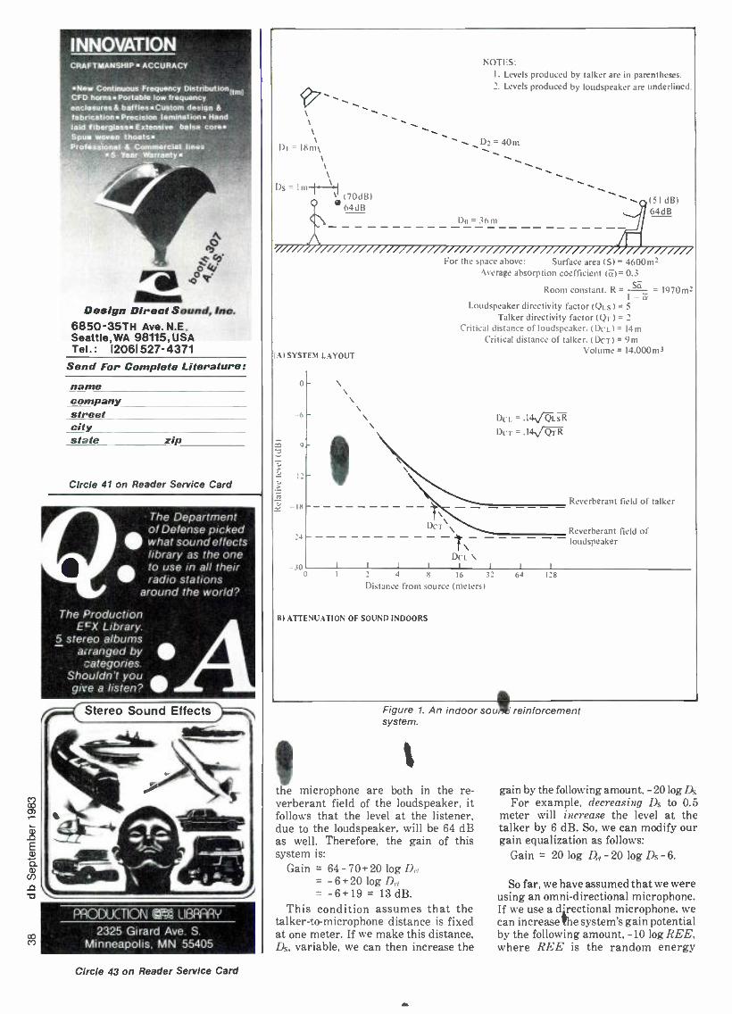
CO
INNOVATION CRAFTMANSHIP ACCURACY
New Continuous Frequency Distribut ionitmi CFD horns Portable low frequency enclosures& bafflesCustom design &
fabrication Precision lamination Hand laid fiberglass Extensive balsa core Spun woven thoats Professional & Commercial lines
5 Year Warranty
Design Direct Sound, Inc. 6850-35TH Ave. N.E. Seattle, WA 98115, USA Tel.: 12061527 -4371
Send For Complete Literature: name company street city state zip
Circle 41 on Reader Service Card
The Department of Defense picked what sound effects library as the one
to use in all their radio stations
around the world?
The Production ECX Library.
5 stereo albums arranged by 3ategories.
Shouldn't you give a listen?
Stereo Sound Effects
PRODUCTION LIBRARY
2325 Girard Ave. S. Minneapolis, MN 55405
Circle 43 on Reader Service Card
Di =18m
Dy - 1 m-t-%1 \ (70dB)
4 64dB
NOTES: I. Levels produced by talker are in parentheses. 2. Levels produced by loudspeaker are underlined.
D2=40m
(51 dB) Jf a4dB
Al SYSTEM LAYOUT
o
-6
-9
12 -
18
300
For the space above: Surface area (S) = 4600m2 Average absorption coefficient (Fri= 0.3
Room constant. R = S-o = 170m2 1 -
Loudspeaker directivity factor (Qt.$) = 5
Talker directivity factor (QT) = 2
Critical distance of loudspeaker. (DCL) = 14m Critical distance of talker. (DcT) = 9m
Volume = 14.000 m3
DcL \ I I I I
DCL = .I41-Q-LSR
DcT = .14\/ QT R
I I
Reverberant field of talker
Reverberant field of - loudspeaker
4 8 16 3'
Distance from source (meters)
B) ATTENUATION OF SOUND INDOORS
64 128
Figure 1. An indoor sou reinforcement system.
t the microphone are both in the re- verberant field of the loudspeaker, it follows that the level at the listener, due to the loudspeaker, will be 64 dB as well. Therefore, the gain of this system is:
Gain = 64 - 70 +20 log D,., = -6 +20 log D,.r
= -6+19 = 13 dB. This condition assumes that the
talker -to-microphone distance is fixed at one meter. If we make this distance, Ds, variable, we can then increase the
gain by the following amount, -20logDD For example, decreasing Ds to 0.5
meter will increase the level at the talker by 6 dB. So, we can modify our gain equalization as follows:
Gain = 20 log D,, - 20 log Ds-6.
So far, we have assumed that we were using an omni -directional microphone. If we use a directional microphone, we can increase !he system's gain potential by the following amount, -10 log REE, where REE is the random energy

Noise generator
Sound system
Sound level meter
POSITION 1
NOTES: System gain = Level position 2, system ON - Level position 2, system OFF
System A = Level position 2, system ON - Level position 1, system OFF
Listeners position
Sound level meter
POSITION 2
efficiency of the microphone, as dis- cussed in last month's column. Recall that REE is a measure of the micro- phone's ability, by virtue of its direc- tional pattern, to reject reverberant information relative to direct, on -axis information. Thus, for a cardioid pat- tern with REE = 1/3, we will gain an additional -10 log 1/3. or 4.8 dB gain potential.
We can now write the gain equation in its final form:
Gain = 20 log D,00 -20 log Ih- 10 log REE -6.
The equation we have developed here gives the maximum gain we can expect of the system. In practice, we can come within a couple of dB in realizing this value -especially if equalization is judiciously applied to reduce any tendency toward acoustical feedback.
FIGURE 2 shows a set -up for measur- ing acoustical gain. A small loud- speaker, typically a 4- or 5 -inch unit, is placed in the normal position of the talker. The response of this loud-
Figure 2. Measurement of system gain and . (delta).
speaker should be uniform over the range from 250 to 4000 Hz. With the reinforcement system turned off, the test loudspeaker is fed a pink noise signal, limited to the range from about 700 Hz to 1.5 kHz, and adjusted to produce a level at the microphone of about 80 dB(A), as measured with a precision sound level meter.
Next, the meter is located at a point well out into the auditorium, and the level there is carefully noted. The system is then turned on and the gain advanced until it is just below the point of feedback. Under this condition, the level at the distant point in the audi- torium is again noted.
Acoustic gain is defined as the difference between these two points in the auditorium.
SYSTEM DELTA (..1). Paul Boner, the fatir of modern
sound reinforcements tern analysis, proposed the quantity D (Greek "delta ")
as a measure of system gain. A .I of zero dB represents the maximum gain a system can possibly produce. Given directional microphones and careful narrow -band equalization, it is possible to approach this value within 2 or 3 dB.
CONCLUSION
It is best to design sound reinforce- ment systems with as much gain margin as possible. This usually means restricting the number of open micro- phones (to be discussed next month), and keeping the value of Ih as small as possible. A fixed podium microphone is of course quite desirable from the user's viewpoint, but this means that Ih is entirely in his hands. The use of a cardioid microphone may increase the gain margin by 3 or 4 dB over an omni- directional one, but critical gain situa- tions will require some kind of personal microphone. such as a lavalier or tie - tack microphone.
w co

Watch Out For Those Lesers! YOU'VE PROBABLY READ the news: "Compact
Discs Revolutionizing the Listening Habits of Many Metropolitan -Area Music Lovers." So says a recent news release from the
Compact Disc Group, a consortium of some 30 record labels and CD manufacturers who devoutly hope CD will actually live up to their PR efforts. The release quotes David Hunt, a local record store manager, who has yet to find a CD "whose sound is less- than -phe- nomenal. Everyone who hears [CD] feels the same way." Dave. meet Doug. In another news release that is mak- ing the rounds. Sheffield Lab president Doug Sax says that, for him, "...all digital attempts thus far have been a failure."
Back to you. Dave. "After exposing some diehard buffs to the Compact Disc. they've offered me their entire record collections, because they don't want to listen to analog again." (Make an offer, Doug.)
Are these guys talking about the same medium? And if so, which one is right? Not trusting our own ears (all that waxy yellow build -up, you know), we called on Michael Tapes, Sound Workshop's resident techno- freak, hi -fi nut. and computer maven, to have a go at it. (See his report in this issue for more details.)
After the report was done, we joined him for some additional listening. A recording of the Goldberg Variations made for an interesting comparison. If one could tune out the traditional analog surface noise. the LP was clearly the sonic winner -in fact, it was no contest. By comparison, the CD sounded filtered.
Is this an indictment of CD, or an indication that other variables need to be carefully studied before coming to any conclusions? Or is it just that in this isolated case. and on this particular system, the LP managed to better survive the playback process? For the moment. there aren't any clear answers, but there are a lot of variables to be considered.
One variable that needs some attention from all of us is the hype factor. As we recall, the last time any- thing sprang to earth fully developed was during the age of mythology. Subsequent miracles have usually taken a bit more time to reach perfection. For example -and contrary to what you read elsewhere -the compact disc did not leap fully mature and all- perfect from its Japanese /Dutch womb. Like all newborns, it will need to be given the chance to crawl, before ex- pecting it to fly. (The db Metaphor Filter is out for cleaning and servicing.)
Yet the local hi -fi press, and the various PR firms, are carrying on as though the new contender has al- ready wiped out the competition. On the other hand, practically every critical listener we've encountered has expressed at least some reservations about the current state of digital audio. This certainly does not mean that its technical validity is under suspicion. But it does suggest that all the questions have not yet been answered, and for the moment at least, analog funeral services might be premature.
This little bit of news has not yet penetrated the minds of some of the digital folks, who are doing their damndest to smother analog audio under a blanket of digital double -speak. Studio Sound Magazine reports of one company which labels its CDs with "Digital Recording," if indeed they are. If they are not, then they are labelled "Digitally Mastered." The word "Analog" (actually, Analogue) is not allowed.
Where does all this leave our beloved source of support -the consumer? Confused, no doubt. And that confusion is being helped along by those who would use the digital mystique to imply that analog record- ings now released in the CD format are, miraculously, "digital." As noted, the "Digitally Mastered" proc- lamation is the truth -but only half of it. You know what the other half of the truth is, but does the con- sumer? In many cases, probably not.
To find out a little more about what it's like out there in Consumerland, SPARS coordinator Gary Helmers wandered into a few West Coast record stores, where various sales people told him everything one needs to know about digital. As one fellow put it, "I don't know what digital means, but it sells records." Another was a little more cautious: "You have to be careful with those lasers; they can hurt you."
Well, perhaps they can, if the rhetoric doesn't poison you first.
Remember quad? Although our beloved FCC was instrumental in killing it off, they certainly were helped along by the industry itself. While waiting for the FCC to get its act together, we were treated to a side -show of preposterous prose on the merits of this or that system. Needless to say, none of the systems had a fighting chance of living up to the claims. Perhaps eventually, but certainly not at birth. The public be- came confused, disenchanted, and eventually, dis- interested.
And now, quad's out, digital's in. It's as perfect today as quad was ten years ago. Let's hope its more enthu- siastic supporters don't promote it right into the ground.
Chances are, they won't be able to do so, although some of them are certainly trying hard. But digital technology seems to have enough going for it to help it survive its birth pains, and its promoters. Even its severest critics recognize the long -term potential of the emerging technology.
Now if only its supporters could acknowledge that tomorrow isn't here just yet, and then get back to the business of today, which is, helping digital audio live up to its potential.
MORE ON AES CONVENTIONS As we reported some months ago, the AES board of
governors voted at its last meeting to return to three conventions a year. Some were pleased- others weren't. Lately. some of those others have been actively campaigning against the three -show schedule.
Still others are wondering why those who don't want three shows a year can't get by simply by not attending the show(s) of their choice. This would leave every- one else free to do as they please, too.
Of course, if there's a show, and you don't go to it, and someone else does, and someone else makes a sale....
Of course, that just couldn't happen here, since the AES is not a selling show. Of course.
So there's really nothing to worry about. If the public doesn't want three AES conventions a year, it won't support three shows a year. Pretty soon, we'll be back to two a year (maybe even one), and nobody will have to do any campaigning to protect the un- enlightened from themselves. Simple, huh? (And remember, you read it here first.) JMW

Before you invest in new studio monitors, consider all the ankles.
No one has to tell you how impor- tant flat frequency response is in a
studio monitor. But if you judge a
monitor's performance by its on -axis response curve, you're only getting part of the story.
Most conventional monitors tend to narrow their dispersion as frequency increases. So while their on -axis response may he flat, their off -axis response can roll off dramatically, liter- ally locking you into the on- axis "sweet spot:' Even worse, drastic changes in the horn's directivity contribute signif- icantly to horn colorations.
Introducing the JBL Bi- Radial Studio Monitors.
At JB1., c've been investigating the relationship between on and off axis frequency response for several years. The result is a new generation of studio monitors that provide flat response over an exceptionally wide range of horizontal and vertical angles. The sweet spot and its traditional restrictions are essentially eliminated.
The key to this improved perfor- mance lies in the unique geometry of the monitors' Bi- Radial horn! Devel- oped with the aid of the latest com- puter design and analysis techniques, the horn provides constant coverage from its crossover point of 1000 Hz to beyond 16 kHz. The Bi- Radial compound flare configuration main- tains precise control of the horn's wide 100° x 100° coverage angle.
I . Patent applied for.
UBL Professional Products Division
\ 6p/in/horizontal
And the Bi- Radial horn's perfor- mance advantages aren't limited to just beadwidth control. The horn's rapid flare rate, for instance, dramatically reduces second harmonic distortion and its shallow depth allows for opti- mal acoustic alignment of the drivers. This alignment lets the monitors fall well below the 131auert and Laws criteria for minimum audible time delay discrepancies.
But while the Bi- Radial horn offers outstanding performance, it's only part of the total package. The new monitors also incorporate J131,s most advanced high and low fre- quency transducers and dividing networks. Working together, these
Polar response comparison ofa typiea/ two - way coaxial studio monitor and JAL's new 4430 Bi-Radial studio monitor from J kHz to lb kHz. a
Jlil, -la.iU hon::ou,d o .,
o ,,..,.:..,.. , o a...,. a
JRI. 441(I centica/
components provide exceptionally smooth response, high power capa- city, extended bandwidth, and extremely low distortion.
Judge For Yourself Of course, the only way to really
judge a studio monitor is to listen for yourself. So before you invest in new monitors, ask your local JBI. profes- sional products dealer for a Bi- Radial monitor demonstration. And consider all the angles.
James B. Lansing Sound, Inc. 8500 Balboa Boulevard PO. Box 2200 Northridge, California 91329 U.S.A.
'JeL harnan.nlernmhonal
AYadable 01 Canada through Gould Marketing. Montreal. Quebec

GREGORY HANKS
Recording Studio Consoles and Film Production Modifying a recording studio console for film production is relatively easy -until Dolby stereo requirements come into play.
THIS ARTICLE WAS JUST going to be about how to modify a recording studio console for use in film production. But before going into how, it might be a good idea to look at why. After all. even though
there are certain similarities between film and record production. there are a lot of important differences, too. Probably the most fundamental difference -from the point of view of the recording engineer -is the manner in which the "final mix" is assembled.
But even before that stage is reached, the "basic tracks" are usually recorded in an entirely different way. When making a record, there is, of course, the artist(s), the engineer and the producer -all working together at the same time, in the same recording studio. When making a film sound track, a lot more variables are involved.
So. let's begin with a little basic film production tech- nique, which may be of specific interest to recording engi- neers whose previous experience is entirely based on LP record production. All you pro' film folks can skip ahead if you like.
While the film is being shot, the director works with the actors and a location sound recordist. Location sound is usually done on quarter -inch tape on a Nagra, using wireless or shotgun microphones. Sync is laid down by the Nagra on the tapes, which are called "dailies." The dailies are num- bered, notated in a log, and taken to a transfer studio where they are transferred to magnetic stock.
The magnetic stock -or simply, "mag " -is a film base coated with ferric oxide -in essence, sprocketed tape. The two major categories of mag are full coat and mag stripe. Full coat is used for three -, four- and six -track recording, while mag stripe is used for mono work.
Once transferred, the mags are "synced to pix," which means making the clapboard (that is, the sound) and the pix fit together. Pix are the prints taken from the film shot the day before. The synchronization process is one where pix and mag are put on a common -spool drive and wound through a' projector /player with parallel sprockets. This is done to verify the proper synchronization of film and sound. The director and primary film editor now collaborate and do a "first assembly," which is actually the preliminary cutting. Once this is done, black -and -white dupes are made.
A number of transfers may be made from the synced mags. These are distributed to the film editor, sound editor(s), and the music -score composer. At this point, the dialogue is refined, looped, and cut to pix. While the dialogue is worked on, the sound effects are refined and any necessary "Foleys" are recorded and cut to pix. Foleys are those sounds produced on a specially- equipped sound effects stage (a Foley Stage).
Next, the composer tries to write a score for the final cut, and record the tracks. The recorded score is then conformed to the final cut.
By this point. the sound track may be comprised of a
Greg Hanks, formerly service manager at Audio- techniques. Inc.. formed Neu. York Technical Support Ltd., which specializes in studio installation and service.
myriad of separate rolls of 35mm mag stock. To keep track of the overall soundtrack continuity. cue sheets are usually made up at the time.
"THE MIX" is approaching! Depending on whether this will be a mono mix or in Dolby stereo. the console will have to meet different requirements. In reality, the "mono mix" is usually a three -track mix (dialogue, music, sound effects) on a four -track recorder. with each track mixed separately. The fourth track is set aside for spare effects.
When film is being mixed, it is done using a collection of mag playback machines, each playing back one to four tracks of a given sound. These playback mags can each be con- sidered analogous to a track on a multi -track tape recorder. Aside from editing, an advantage is that at any time in the production, any sound effect may be moved forward or back, in relative time to the track.
Each of these tracks is fed to the console, as is the music, and depending on the type of sound, sent to its corresponding bus. The recording is usually done on a four -track "pick -up" type of mag recorder, capable of inaudible punch -ins. Monitoring is done off the playback head at all times so that when the bus is monitored it is displaced in time by two frames (universally, the distance between the record and play heads).
When the sound is monitored, it is heard as a combined mono signal coming from the center of the projection screen. The monitor system is usually comprised of a bus /mag selector, a bus (track) solo system. switchable Academy equalization, and a mute and level control.
DOLBY STEREO With Dolby stereo mixing. the personality of the console
changes considerably. This may be noted in the change of bus functions.
With mono sound tracks, the buses are used for the discrete combination of music, dialogue, and effects, whereas in Dolby stereo the buses are used for relative location assign- ment instead. What this means in practical terms is that no longer is the film mixer afforded the luxury of building the discrete bus, which can later be changed with relative ease. Instead. the sound effects must be married to the dialogue. The music level is no longer handled with a sub -master. but is mixed pretty much as in a record production.
The four tracks used in Dolby stereo are left, center. right and surround. When recording in the Dolby format. the console is the same one that was used last week for a mono production. This means that what was last week's music bus (track 2) is this week's hard -center soundtrack. The effi- ciency of the change of roles is determined by the flexibility of the console and the imagination of the operator.
Before looking at the console in greater detail. perhaps it would be a good idea to review the basics of Dolby stereo. First of all, mono films are optically striped with a single track on one side of the film. The Dolby stereo optical track is different in that, like a phonograph record, each side of the optical track carries different information. Dolby has also made significant changes in the way we "see" motion picture sound. The differences are that noise reduction is used on the playback of the optical track, and one -third octave

Inl
o
Fader
Y.yuahi:i
I.1^ir.uider I
'* omlor
i -,SAN-- 4
level
_---_fl .
To monitor system
Figure 1. Console block diagram.
equalization is used in the theater playback system. The Dolby four -channel sound is encoded intotwochannels. using a phase- matrix system.
During playback, the signal is decoded witheithera Dolby (7 P50 or a CP200. After decoding, the signal is sent to four one -third octave equalizers (required as part of the license agreement to show Dolby films). and then to the power amplifiers.
In the film studio. the encoding process for this four - channel system is handled by a unit called the DS -4. The Dolby DS -4 does much more than just encode four channels of information to two channels. It is a vital part of the record- ing studio chain during the entire mixing process. Because the matrix encoded uses phase information for directional cues. the matrix decoding is somewhat touchy when it comes to some source material. For this reason. all monitor signals are first encoded and then decoded before getting to the monitor amplifiers in the studio. The DS -4 does all this, as well as providing a mono compatibility check and additional metering inside the encode /decode chain.
The job of the classic film console is easily defined as a system that will combine many (up to and exceeding 56) sources on three or four different buses. As noted earlier, the standard configuration is dialogue, music, sound effects. extra effects.
Each input module usually provides: a channel fader, equalization (usually of the stepped type to accommodate repeatable settings), PFI, and /or Solo, usually pre -equalization, discrete (usually. one to four) bus assignment. At times the send buses are ganged with the main assigns to marry the effects send to the main track. The buses are usually sub -grouped, with the return of the
married send buses returned before the sub -master. The groups are matrix -selected to the different tracks of the mag film recorder. A board master is most commonly provided.
The monitor section of the film console provides: mono fold -down of the four tracks. Academy equalization of the monitor output.
bus /mag selection for the four tracks /buses (pre -fold- down). Generally. this selector is a master selector for all tracks, track solo, which is a facility to solo the individual tracks. monitor mute /dim. This is an overall function. A block diagram of the standard console is shown in
FIGURE 1. As can be seen in the figure, a standard mono film console is a relatively simple device. With a little creativity in patching, almost any recording console can fulfill film requirements. The four buses could be the first four buses of the console. The bus /mag select of the monitor could be the multi -track monitor bus /tape switch. The monitor section of the console is set up with tones for unity fold -down to mono. and most consoles have some facility for track soloing. The effects returns would be brought back to the input modules, and the sends could use the second set of four buses.
When using a recording console for film recording, the important thing to keep in mind is that the pan pots should never be in the circuit and the monitor of the four buses that feed the mag recorder should be level- matched, never touched, and combined to mono in the monitor. Console crosstalk should be very low, and the noise of the input channels should allow for multiple passes through the board without any noise contribution.
This all sounds simple enough, and it is. At least, it is a very simple thing to do mono recording on a multi -track recording console. However, Dolby stereo is quite another matter.
Let's look at Dolby stereo requirements with a function -by- function description of the console.
INPUT MODULE The input module should be able to send the signal (after
the common facilities of level, equalization, etc.) to any one of four discrete buses in the mono mode, and send the same signal through a pan pot to the same four buses in the stereo mode. The panning should be left -to- right, left (or right) -to- center, left (or right) -to- surround, and center -to- surround. One essential aspect of the pan pot is that it must be down
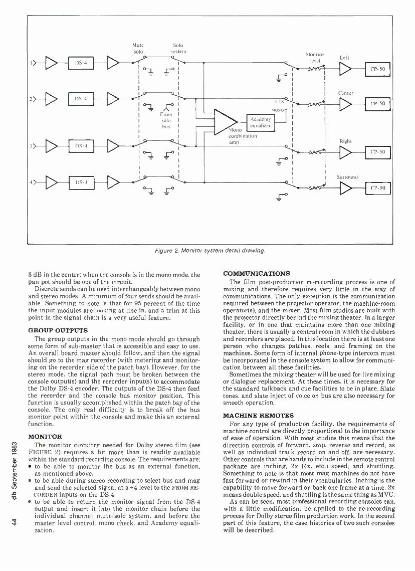
Mute solo
Solo system
_r°
o-1 From solo bus
So
Academy equalizer
\lono combin lion amp
4 -TR
)IOVOQ
r°
Monitor Left
level
r Center
CP-50
CP-50
Right
CP -50
Surround
CP -50
Figure 2. Monitor system detail drawing.
3 dB in the center; when the console is in the mono mode, the pan pot should be out of the circuit.
Discrete sends can be used interchangeably between mono and stereo modes. A minimum of four sends should be avail- able. Something to note is that for 95 percent of the time the input modules are looking at line in, and a trim at this point in the signal chain is a very useful feature.
GROUP OUTPUTS The group outputs in the mono mode should go through
some form of sub -master that is accessible and easy to use. An overall board master should follow, and then the signal should go to the mag recorder (with metering and monitor- ing on the recorder side of the patch bay). However, for the stereo mode, the signal path must be broken between the console output(s) and the recorder input(s) to accommodate the Dolby DS -4 encoder. The outputs of the DS -4 then feed the recorder and the console bus monitor position. This function is usually accomplished within the patch bay of the console. The only real difficulty is to break off the bus monitor point within the console and make this an external function.
MONITOR The monitor circuitry needed for Dolby stereo film (see
FIGURE 2) requires a bit more than is readily available within the standard recording console. The requirements are:
to be able to monitor the bus as an external function, as mentioned above, to be able during stereo recording to select bus and mag and send the selected signal at a +4 level to the FROM RE- CORDER inputs on the DS -4, to be able to return the monitor signal from the DS -4 output and insert it into the monitor chain before the individual channel mute /solo system, and before the master level control, mono check, and Academy equali- zation.
COMMUNICATIONS The film post -production re- recording process is one of
mixing and therefore requires very little in the way of communications. The only exception is the communication required between the projector operator, the machine -room operator(s), and the mixer. Most film studios are built with the projector directly behind the mixing theater. In a larger facility, or in one that maintains more than one mixing theater, there is usually a central room in which the dubbers and recorders are placed. In this location there is at least one person who changes patches, reels, and framing on the machines. Some form of internal phone -type intercom must be incorporated in the console system to allow for communi- cation between all these facilities.
Sometimes the mixing theater will be used for live mixing or dialogue replacement. At these times. it is necessary for the standard talkback and cue facilities to be in place. Slate tones, and slate inject of voice on bus are also necessary for smooth operation.
MACHINE REMOTES For any type of production facility, the requirements of
machine control are directly proportional to the importance of ease of operation. With most studios this means that the direction controls of forward, stop, reverse and record, as well as individual track record on and off, are necessary. Other controls that are handy to include in the remote control package are inching, 2x (4x, etc.) speed, and shuttling. Something to note is that most mag machines do not have fast forward or rewind in their vocabularies. Inching is the capability to move forward or back one frame at a time, 2x means double speed, and shuttling is the same thing as MVC.
As can be seen, most professional recording consoles can, with a little modification, be applied to the re- recording process for Dolby stereo film production work. In the second part of this feature, the case histories of two such consoles will be described.

The following sidebar was written by Mel Zelniker of Sound One Corp. Mel is one of New York's more promi- nent film mixers. This is often given to clients preparatory to their coming to the mix.
Mixing Tips for Dolby Stereo
In today's world of production deadlines and squeezed budgets, the preparation and completion of a Dolby stereo mix represents a formidable task for both editor and mixer. On the East Coast, where film mixers usually work on mixing desks designed for single -seat flying, it is of paramount importance that the prep work done by the sound editorial team be organized in a most efficient manner.
For obvious anatomical reasons, the mixer is not going to handle the entire track inventory for each reel at one time. He is going to pre -mix. How these premixes are organized can spell the difference between a smooth creative mix and a battle.
As in traditional stereo, a signal sent equally to left and right is perceived as mono or "phantom center." In very wide theaters the phantom center may present perceptual problems to the viewer seated very far off the center -screen axis. Keep this poor guy in mind; we will get back to him in a moment.
The first premix will be for dialogue. We have found that it makes things neater if certain effects textures are added during the dialogue premix. Most of the time, the dialogue is going to come from channel 2 or hard center. We have found that the production "room tones" that are used to fill editorial gaps in the dialogue track work best if they are also sent to hard center. The same applies to "production effects," i.e. those effects actually recorded while dialogue action was taking place. In traditional mono editorial technique, these are usually split off onto the effects track of the master. In stereo however, we have found that for the off -axis viewer the sound "images" more realistically when sounds made by center- screen action come from hard center, as opposed to phantom center. For this reason we lay out our dialogue pre -mix as follows:
Track 1, dialogue. Track 2, alternate dialogue and /or dubbing lines. Track 3, production effects, Track 4, room tones. In the final mix these all go
hard center. In addition, we will at times also lay down the Foley
tracks along with the production effects. Now the fun begins. We begin our stereo pre- mixes.
We generally approach effects first. There is no cut - and -dried rule of thumb here. Atmospheres such as sea shores or airport backgrounds work wonderfully when recorded in stereo. In addition, the editorial staff will have prepared specific sounds to be placed left, right or on the surround channel. You can surround yourself in a jungle with monkeys chattering behind you, elephants on the right and birds on the left. It's all up to the imagination, and it's what makes a stereo picture sound so alive. But treat these pre -mixes with caution. If it isn't planned right, you can get trapped.
First, always have your dialogue premix up for listening purposes. We are able to monitor the premix while recording the effects premix. This allows us to
set an idea of the rough balances between the hard center and the stereophonic tracks.
Second, we like to break our effects premixes down to at least two units so that backgrounds from one scene are not butted up against the next scene. This involves editorial preparation so that these back- grounds are "checkerboarded." Later, when all the premixes are up and running at the final mix. you have the freedom to change the relationships from scene to scene without the need to do "on the frame" punch -ins.
Third, while it's possible to accommodate a certain amount of panning during these premixes, you can do a better job if the big action scenes with a lot of cross - screen panning are handled as a separate pass.
And fourth, treat the surrounds with respect. We never know how the surround channel is going to be set up out there in theatreland. It is the most variable aspect of any Dolby theater. Therefore, we have had the most success in treating it as a special effects channel. Experience has shown us that it is not smart to place constant information in the back of the theater. Also, for reasons best left to a more technical dis- cussion, too much reliance on surround can do ugly things to mono compatibility.
At this point we have at least three pre -mixes avail- able to us: the dialogue, and effects #1 and effects #2. We may have even more. Now comes the music. "Source" music (music coming from a radio or TV seen on the film screen), is generally mono. We place it in phantom center. The score is stereo, naturally. Nowadays it has become increasingly common to have the score divided into eight or more tracks for each cue. This is done because experience has shown that the balances achieved in the recording studio do not always prove to be the same when heard against dialogue and effects. Fletcher Munson, cinema equalization, and theatre acoustics all come into play. So here we are with Music elements A through E, some involving 12 faders, and the music department is asking for six cross -dissolves in 45 seconds of screen time. We're going to have to pre -mix again.
At this point, all things being equal, you are ready for that magic moment. Everything has been done right. Dialogue is smooth, the effects pre -mixes mesh one to the next, and your music is in manageable form. With an occasional hand from the people around you, the process by which all these elements come together begins. Soon you'll have the pleasure of seeing and hearing a Dolby stereo film. Mono just isn't the same.
It should be noted that this was written from the standpoint of a one -man mix. Rules are made to be broken and nothing is boilerplate. The organizational and editorial suggestions given here have worked for us. Any other suggestions would be appreciated.
As can be seen from the preceding paragraphs, film requires editorial coordination between engineering and production well beyond that expected in the record industry.

CO
JOHN MONFORTE
dbi Tee ©p© rr 4
The Bruel & Kjaer Studio Microphones
BRUEL & KJAER INSTRUMENTS. INC. of Naerum, Denmark, have introduced a series of micro- phones designed for use in the professional record- ing studio. Audio professionals are already fa-
miliar with B & K's main product line, consisting of a com- plete spectrum of audio test equipment used for research and manufacturing. A look at the response curves supplied with your favorite microphone or at the polar curve of your monitor speakers will probably reveal that the equipment used to do the measurements was made by B & K. In fact, the majority of B & K's products are concerned with acoustic calibration. While it is not the point of this review to extol the virtues of B & K's sound level meters or Fast- Fourier Transform analyzers, it is important to note that the ultimate accuracy of these devices depends upon using reference - quality microphones. These microphones are called instru- mentation microphones because they are inherently special- ized for the purpose of making accurate measurements and not for making music. B & K's instrumentation micro- phone line consists of a dozen models, each specializing in different frequency ranges or different signal levels.
Within the B & K instrumentation level, it's no problem to find a model designed for the frequency range of 20 Hz to 20 kHz, and for levels from 20 to 150 dBSPL. In fact, there are two of them, differing in directional responses due to wavelength losses (to be described later). It would seem that such a microphone, designed to maximize frequency re- sponse and minimize noise and distortion, would be very transparent when recording music. This, also, is true. In fact, these microphones have been used to record several audio- phile records and even some more -popular music, such as the Grateful Dead and the Charlie Daniels Band. However, unlike regular studio -type microphones, instrumentation transducers have several limitations for this type of applica- tion.
After the enthusiastic recording engineer shells out over $1000 for each capsule and preamp, he must then build a device to deliver 200 volts to polarize the capsule and provide some other voltages to power the electronics. He is then left with a signal that is unbalanced and has a non -standard level, so he might as well build some mic preamps that can be located close to the microphones. The few engineers who go through this much trouble may indeed be rewarded with an excellent recording, but must still be prepared to cope with the consequences of using the microphone outside its designed environmental limitations. You see, instrumenta- tion microphones are designed for a "controlled" environ- ment. Location recordings are usually done in places where the environment (notably temperature and humidity) cannot be controlled. Even in the recording studio, an instrumenta- tion mic could not survive the humidity or cigarette smoke from a close -mic'ed vocal any better than it could survive being whacked by a mis- directed drumstick.
The first obstacles to overcome were the environmental ones. It was obvious to B & K that an electret element, having no polarization requirements, and with the ability to withstand environmental extremes, was the solution. How- ever, electrets have had other difficulties that precluded
John Monforte is a member of the faculty of the University of Miami's Music Engineering Program.
them from being laboratory quality. Electrets are not inherently inferior, but there were many technological obstacles to overcome to raise the electrets to the quality level of the polarized condensers. Nevertheless, B & K set about the task a few years ago, and produced a series of capsules designed to retrofit the polarized ones -and do so at a cost savings.
Being sensitive to the needs of the recording business, B & K directed their efforts toward producing a series of microphones that would be compatible with recording studio line requirements. The result of these efforts are the microphones reviewed here. This series consists of four microphones. Two of them, models 4003 and 4006, have 16mm capsules while the others, models 4004 and 4007, have 12mm capsules. The smaller diameter version is capable of extended high frequency response, better transient response, less distortion and truer omni -directional characteristics. All this is obtained at the expense of sensitivity. For each microphone diameter, there is a choice of powering sources. Types 4006 and 4007 are standard P48 phantom compatible. Types 4003 and 4004 use a separate power supply, type 2812, that eliminates the transformer, operates the electronics at higher voltages for increased headroom, and supplies a line - level output that is less sensitive to capacitive loading and can deliver a balanced or unbalanced output. Although these types also use standard XLR -type connectors, the cable run between the microphone and supply should be kept fairly short because the signal here is both unbalanced and low level.
THE MICROPHONES Each microphone comes with a high -quality mic cable and
a sturdy mahogany case. Included in the case is a foam windscreen, mic stand adaptor and, of course, a very thorough calibration chart. Each microphone is individually measured for frequency response, sensitivity and self -noise level. The 16mm microphones also include a replacement protection grid with a different slot pattern in it. The purpose of this grid is to correct the frequency response when the microphone is used in a diffuse sound field. At 0 degree incidence, the diaphragm is presented with only one compression or rarefaction (see FIGURE 1). Therefore, no cancellation is possible. But all microphones of finite size are subject to the effects of wavelength loss when a wavefront presents the diaphragm with more than one compression or rarefraction at a time, causing some cancellation of the signal as measured by the microphone. This effect is more pronounced as the diameter of the diaphragm is increased and the cancellations begin occurring at lower frequencies. On -axis signals will always sound brighter than off -axis ones, but the selection of the proper grid gives the microphone either flat response to on -axis sources, or flat response over an average of all angles of incidence. When using any microphone for distant mic'ing where reverberation becomes a significant part of the signal, or for close section mic'ing, it is best to use the latter grid and orient the element at 90- degree incidence.
Most seasoned engineers are familiar with this phenom- enon and adjust the incidence angle to fine -tune the high frequency balance of the sound, especially since many popular studio microphones have capsules that can be as large as one inch in diameter. The fact that B & K is
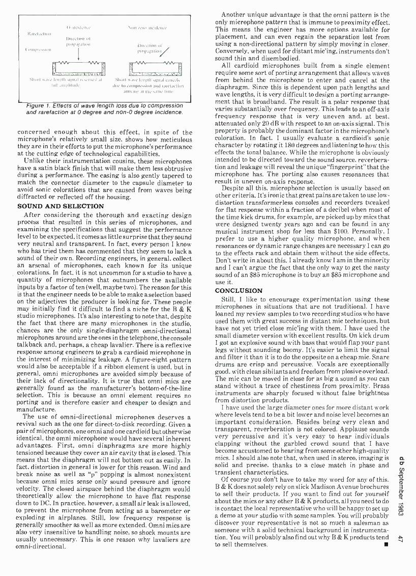
Rare l action
('um pression
O
Shull ,s a,. Irnélh srnal is s.m.J .il Rill .unpllmd,
Non /ero incidence
Uireclinn of propapalioll /
Shun . cmrcls due lo compression and r: rela.non
arm ine al the sain, inns.
Figure 1. Effects of wave length loss due to compression and rarefaction at 0 degree and non -0 degree incidence.
concerned enough about this effect, in spite of the microphone's relatively small size, shows how meticulous they are in their efforts to put the microphone's performance at the cutting edge of technological capabilities.
Unlike their instrumentation cousins, these microphones have a satin black finish that will make them less obtrusive during a performance. The casing is also gently tapered to match the connector diameter to the capsule diameter to avoid sonic colorations that are caused from waves being diffracted or reflected off the housing.
SOUND AND SELECTION After considering the thorough and exacting design
process that resulted in this series of microphones, and examining the specifications that suggest the performance level to be expected, it comes as little surprise that they sound very neutral and transparent. In fact, every person I know who has tried them has commented that they seem to lack a sound of their own. Recording engineers, in general, collect an arsenal of microphones, each known for its unique colorations. In fact, it is not uncommon for a studio to have a quantity of microphones that outnumbers the available inputs by a factor of ten (well, maybe two). The reason for this is that the engineer needs to be able to make a selection based on the adjectives the producer is looking for. These people may initially find it difficult to find a niche for the B & K studio microphones. It's also interesting to note that, despite the fact that there are many microphones in the studio, chances are the only single- diaphragm omni -directional microphones around are the ones in the telephone, the console talkback and, perhaps, a cheap lavalier. There is a reflexive response among engineers to grab a cardioid microphone in the interest of minimizing leakage. A figure -eight pattern would also be acceptable if a ribbon element is used, but in general, omni microphones are avoided simply because of their lack of directionality. It is true that omni mics are generally found as the manufacturer's bottom -of- the -line selection. This is because an omni element requires no porting and is therefore easier and cheaper to design and manufacture.
The use of omni -directional microphones deserves a revival such as the one for direct -to -disk recording. Given a pair of microphones, one omni and one cardioid but otherwise identical, the omni microphone would have several inherent advantages. First, omni diaphragms are more highly tensioned because they cover an air cavity that is closed. This means that the diaphragm will not bottom out as easily. In fact, distortion in general is lower for this reason. Wind and break noise as well as "p" popping is almost nonexistent because omni mics sense only sound pressure and ignore velocity. The closed airspace behind the diaphragm would theoretically allow the microphone to have flat response down to DC. In practice, however, a small air leak is allowed, to prevent the microphone from acting as a barometer or exploding in airplanes. Still, low frequency response is generally smoother as well as more extended. Omni mics are also very insensitive to handling noise, so shock mounts are usually unnecessary. This is one reason why lavaliers are omni -directional.
Another unique advantage is that the omni pattern is the only microphone pattern that is immune to proximity effect. This means the engineer has more options available for placement, and can even regain the separation lost from using a non -directional pattern by simply moving in closer. Conversely, when used for distant mic'ing, instruments don't sound thin and disembodied.
All cardioid microphones built from a single element require some sort of porting arrangement that allows waves from behind the microphone to enter and cancel at the diaphragm. Since this is dependent upon path lengths and wave lengths, it is very difficult to design a porting arrange- ment that is broadband. The result is a polar response that varies substantially over frequency. This leads to an off -axis frequency response that is very uneven and, at best, attenuated only 20 dB with respect to an on -axis signal. This property is probably the dominant factor in the microphone's coloration. In fact, I usually evaluate a cardioid's sonic character by rotating it 180 degrees and listening to how this effects the tonal balance. While the microphone is obviously intended to be directed toward the sound source, reverbera- tion and leakage will reveal the unique "fingerprint" that the microphone has. The porting also causes resonances that result in uneven on -axis response.
Despite all this, microphone selection is usually based on other criteria. It's ironic that great pains are taken to use low - distortion transformerless consoles and recorders tweaked for flat response within a fraction of a decibel when most of the time kick drums, for example, are picked up by mies that were designed twenty years ago and can be found in any musical instrument shop for less than $100. Personally, I prefer to use a higher quality microphone, and when resonances or dynamic range changes are necessary I can go to the effects rack and obtain them without the side effects. Don't write in about this. I already know I am in the minority and I can't argue the fact that the only way to get the nasty sound of an $85 microphone is to buy an $85 microphone and use it. CONCLUSION
Still, I like to encourage experimentation using these microphones in situations that are not traditional. I have loaned my review samples to two recording studios who have used them with great success in distant mic techniques, but have not yet tried close mic'ing with them. I have used the small diameter version with excellent results. On kick drum I got an explosive sound with bass that would flap your pant legs without sounding boomy. It's easier to limit the signal and filter it than it is to do the opposite on a cheap mic. Snare drums are crisp and percussive. Vocals are exceptionally good, with clean sibilants and freedom from plosive overload. The mic can be moved in close for as big a sound as you can stand without a trace of chestiness from proximity. Brass instruments are sharply focused without false brightness from distortion products.
I have used the large diameter ones for more distant work where levels tend to be a bit lower and noise level becomes an important consideration. Besides being very clean and transparent, reverberation is not colored. Applause sounds very percussive and it's very easy to hear individuals clapping without the garbled crowd sound that I have become accustomed to hearing from some other high -quality mies. I should also note that, when used in stereo, imaging is solid and precise, thanks to a close match in phase and transient characteristics.
Of course you don't have to take my word for any of this. B & K does not solely rely on slick Madison Avenue brochures to sell their products. If you want to find out for yourself about the mies or any other B & K products, all you need to do is contact the local representative who will be happy to set up a demo at your studio with some samples. You will probably discover your representative is not so much a salesman as someone with a solid technical background in instrumenta- tion. You will probably also find out why B & K products tend to sell themselves.
V

JOHN T. MULLIN
Long Players -Long Gone The following historical sketch focuses on the earliest days of the LP
PART OF A REPLY to a letter from F. G. Greenberg S g in the December, 1982, issue, db issued a request for information about the very earliest days of the LP at RCA or elsewhere. As many of you may
know, I have collected apparatus and information related to the subject of sound recording over the past fifty years. In fact, I had considerable exposure to the RCA Victor Long Playing record project (as an observing teenager) when it was trying to learn to fly.
Therefore, this should be a good time to contribute some commentary on this apparently elusive subject before I, or others of my vintage having memories of it, are no longer on the scene.
Much of this historical sketch may be verified by observa- tion and photography of items in my collection. As a matter of fact, as I write this I have just finished checking the play- ing time of a most remarkable phonograph record developed by Mr. Edison and marketed in 1926. It is a 12 -inch disc employing vertical modulation, running at 80 rpm and - Aha! it just ended one side after 21 minutes! Calculations show that it has 450 lines per inch. (Note I do not say grooves per inch -there is only one groove on each side of a record.) May we safely say there was a "super -micro-groove" record marketed before there ever was any "Micro-Groove," and that Long Playing doesn't necessarily mean 331/3 rpm?
Edison's long player was destined at the outset to be a disaster. He hated anything to do with amplifier tubes (NIH ?), and insisted on recording acoustically at reduced volume level while everyone else was into electrical record- ing at higher volume without that tin horn sound. If that wasn't enough, the diamond stylus kept jumping grooves and tearing up the record surface.
With this the 80 rpm exception, all subsequent develop- ment of long playing records incorporated the record speed of 33'/3 rpm. Why this speed?
THE 331/3 rpm DISC Bell Labs, having been fully involved in the development
of electrical phonograph recording, was now interested in adapting this apparatus to the motion picture. There was a prevailing lack of confidence in photographic methods of sound recording, and the disc promised to be a practical alternative, if the playing time could be increased to match the maximum running time of a reel of film -eleven minutes.
After careful analysis of the problem, it was decided that a 16 -inch diameter disc, running at 33'/3 rpm, would be the optimum record format. The groove pitch could be selected from three provided on the special recording lathe, 86, 92, or 98 lines per inch, all typical of what had long been employed in phonograph work. The system used the standard 78 rpm groove shape and changeable steel needles. Masters were cut from inside to outside of the disc and pressings were made in high quality shellac, the same material used for phono-
4 If it weren't for Jack Mullin, we would still be recording on wire.
graph records. A new steel needle could easily trace the higher frequencies at the inside of the disc where the velocity was lowest. As the needle point wore off, the groove velocity increased toward the outer edge of the record, effectively compensating for the high- frequency losses that otherwise would be most evident at the moment of changeover from reel and disc to reel and disc. Naturally a new needle was used at the start of each playing and the label had a series of numbered blocks which were to be checked off with a pencil at each playing. After all blocks (typically 20) were checked, the record was to be discarded. Such drastic wear of the record was caused by the weight of the oil- damped pickup, which was about four ounces.
With the simple refinement of increasing the groove pitch to 125 lines per inch, a full 15 minutes could be recorded, and thus was born the "electrical transcription" for radio broadcasting. These records were initially syndicated fifteen -minute or half -hour programs widely distributed to independent stations not affiliated with land -line networks. Again, they were pressed in shellac. The necessity of using wax for recording made recording at individual stations highly impractical until the introduction of the lacquer - coated aluminum disc.
By 1931 RCA Victor had completed design and began manufacture of apparatus to play a form of 33'/s rpm disc in the home. It was introduced with a highly impressive press demonstration on September 17, 1931. The complete Fifth Symphony of Beethoven was played from a single twelve - inch disc, where a previous 78 rpm version of the same work in the Victor catalog required five discs. Obviously Victor had done something more than change speed. With standard grooves, 33'/3 rpm would have given only 2.34 times the playing time of a 78 rpm disc. These records had a much finer groove, with 150 lines to the inch, and they were pressed in a plastic material which RCA had been using for a time in pressing 16 -inch records for radio broadcast. It was called Victrolac. I have several of them in my collection and they look and feel very much like today's records.
VITROLAC Because the groove was closer to Micro -Groove than
standard, a special chromium -tipped and highly polished needle was employed to play them. It had an orange colored shank for identification. Standard 78s were to be played with a green shank needle, chrome tipped with a more rounded tip. Woe be the Victrolac if one failed to change to the proper needle when changing from 78 to long -playing record!
I well remember the fragility of these records and other factors conspiring to bring about their destruction. All RCA Victor pickups at the time were of the magnetic horseshoe configuration, mounted on the famous "Cobra" arm seen in FIGURE 1. The wings contained lead weights intended to keep the entire assembly free from rotational vibration when excited by low frequencies -a somewhat futile attempt at improving the low frequency signal output. The mass of this assembly and its weight caused merciless wear of the plastic records and if perchance one bumped against the
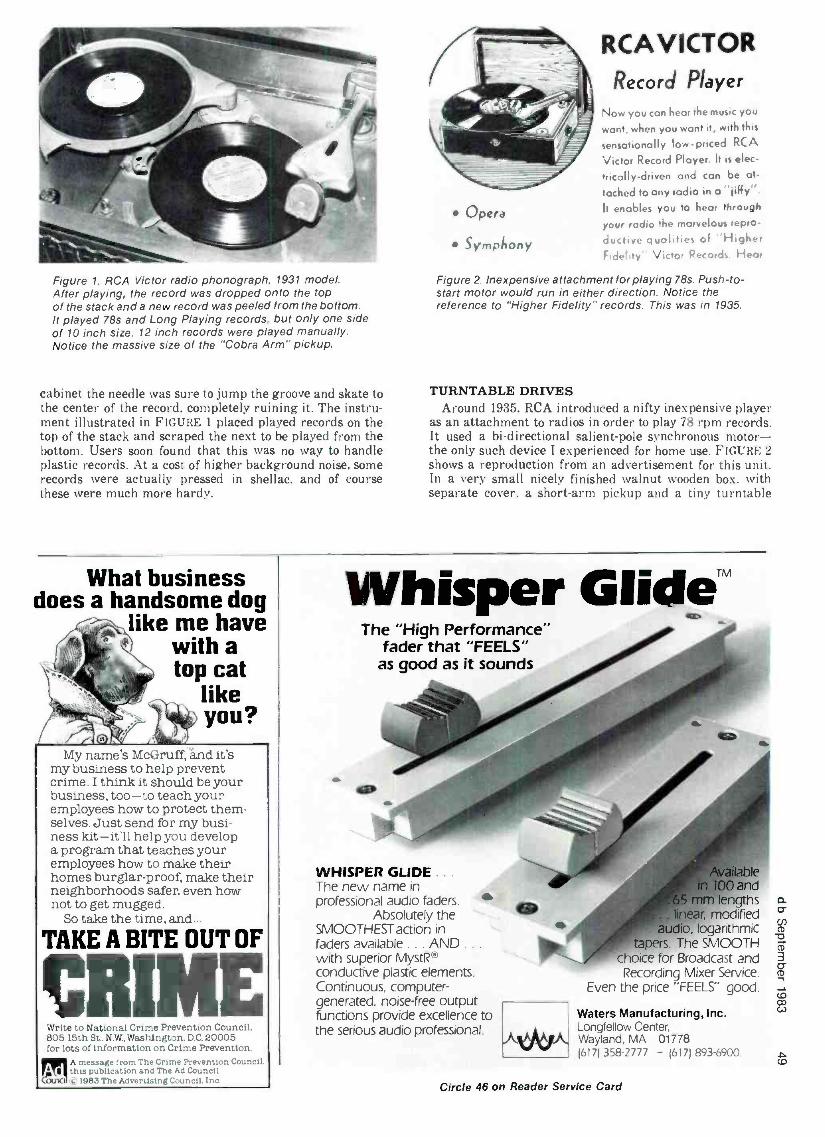
Figure 1. RCA Victor radio phonograph. 1931 model. After playing, the record was dropped onto the top of the stack and a new record was peeled from the bottom. It played 78s and Long Playing records, but only one side of 10 inch size. 12 inch records were played manually. Notice the massive size of the "Cobra Arm" pickup.
cabinet the needle was sure to jump the groove and skate to the center of the record. completely ruining it. The instru- ment illustrated in FIGURE 1 placed played records on the top of the stack and scraped the next to be played from the bottom. Users soon found that this was no way to handle plastic records. At a cost of higher background noise, some records were actually pressed in shellac, and of course these were much more hardy.
Opera
Sympñony
RCAVICTOR Record Player
Now you con hear the music you
wont, when you want it, with this
sensationally low- priced RCA
Victor Record Player. It is elec-
trically- driven and can be at-
tached to any radio in o "jiffy ". It enables you to hear through
your radio the marvelous repro-
ductive qualities of "Higher F dc' t y ' Victor Records Hear
Figure 2. Inexpensive attachment for playing 78s. Push -to- start motor would run in either direction. Notice the reference to "Higher Fidelity" records. This was in 1935.
TURNTABLE DRIVES Around 1935, RCA introduced a nifty inexpensive player
as an attachment to radios in order to play 78 rpm records. It used a bi- directional salient -pole synchronous motor - the only such device I experienced for home use. FIGURE 2 shows a reproduction from an advertisement for this unit. In a very small nicely finished walnut wooden box, with separate cover, a short -arm pickup and a tiny turntable
What business does a handsome dog
like me have with a
(; t top cat like
Ra lmk you? My name's McGruff, and it's
my business to help prevent crime. I think it should be your business, too -to teach your employees how to protect them- selves. Just send for my busi- ness kit -it'll help you develop a program that teaches your employees how to make their homes burglar -proof, make their neighborhoods safer, even how not to get mugged.
So take the time, and...
TAKE A BITE OUT OF
RI Write to National Crime Prevention Council, 805 15th St., N.W., Washington, D.C. 20005 for lots of information on Crime Prevention.
M A message from The Crime Prevention Counc:
L this publication and The Ad Council. c 1983 The Advertising Council. Inc.
Whisper Glide`M The "High Performance"
fader that "FEELS" as good as it sounds
WHISPER GLIDE . .
The new name in professional audio faders.
Absolutely the SMOOTHEST action in faders available ... AND .. .
with superior MystR® conductive plastic elements. Continuous, computer - generated, noise -free output functions provide excellence to the serious audio professional.
ngths modified
, logarithmic The SMOOTH
hoice for Broadcast and Recording Mixer Service.
Even the price "FEELS" good.
Waters Manufacturing, Inc. Longfellow Center, Wayland, MA 01778 1617) 358 -2777 - (617) 893 -6900.
Circle 46 on Reader Service Card

Figure 3. Planetary reduction gear assembly used in the first models of two speed drives for home radio phonographs by RCA Victor.
was mounted. The illustration shows a 10 -inch record in place. It could play 12 -inch records of course, with horrible tracking error at the start of the record, but nobody worried much about that in those days. The motor was extremely simple. A stator containing the exciting coils facing outward was surrounded by the rotor rigidly mounted to the under- side of the platen. The rotor had 92 teeth projecting inward and matched to teeth projecting outward from the stator. With 60 -cycle current applied to the coils, the rotor would lock at 78.26 rpm when started by hand in either direction. The Saja motor was a much more refined version of this drive. available either in 78 or combination 78 and 331/:+ ver- sions, and had been manufactured in Europe for several years.
Such turntable drives were anticipated some time earlier by the Western Electric 203A Reproducer Set, introduced in the 1920s. This contained two 78 turntables and oil - damped pickups for use in radio stations and for intermission music in theatres. The motors were made by Crocker -Wheeler and employed a direct -drive eddy current copper disc 121/1
inches in diameter to accelerate the rotor to sync speed whereupon the salient -pole rotor and matching stator locked the speed at 78.26 rpm.
However, when RCA introduced the Long Playing record to the home market. this type of motor was not used at all. All of their machines that I ever encountered used a con- ventional shaded pole or capacitor synchronous motor with an 1800 rpm rotor locking on speed either by having a salient pole or hysteresis rotor. The rotor shaft carried a worm -and- thrust bearing at one end. The worm drove a helical gear on the turntable spindle. In all cases the latter shaft ran at 78.26 rpm.
In the earliest version. a planetary assembly, shown in FIGURE 3, was slipped over the vertical shaft. The shaft end, projecting through the assembly, supported the turntable platen. A shift lever (FIGURE 4) allowed thisentire assembly and the turntable to rotate at 78 rpm or immobilized the frame of this assembly. The turntable was then driven through the reduction gears at 331/3 rpm while the shaft remained running at 78. In a recent test I performed on one of these drives I found the wow- and -flutter to be intolerable at 331/3 rpm. It was indeed a very poor design.
Within a year or two a much improved drive was intro- duced. The design was patterned after RCA's very success- ful two -speed turntable intended for professional broadcast use. The home version was simple and inexpensive and performed remarkably well. It was also capable of being fitted to earlier single -speed radio phonographs, although RCA does not seem to have done much to press this feature. The entire two -speed apparatus was built into the bottom
Figure 4. Drive assembly in place on vertical drive spindle. Note the shift lever used to catch and immobilize the planetary reduction frame to attain 33'/3 rpm.
of the turntable platen. It is shown in FIGURE 5 with its small dust cover removed. revealing a ball- bearing type assembly containing only three steel balls. The 78 -rpm drive shaft from the motor is keyed to the slotted hub which also provides the inner ball race. The small lever attached to the outer ball race is spring loaded so that one of its ends rests in one of four notches in a ring rigidly attached to the turntable platen. The balls are equally spaced in their ball cage, which is also rigidly mounted to the platen. In this situation the entire assembly. including the platen, rotates at 78 rpm.
An external two- position slide. mounted on the motor board and not shown in the illustration, clears the little lever on the outer ball race when it is in its outer position: when advanced to its inner position it catches the free end of the lever and entraps it. This causes its other end to be lifted out of the notched ring and hold the outer ball race stationary. Since the balls now roll around between the inner and outer races, they cause the ball cage and the platen attached to it to rotate at 331/3 rpm.
Because there is very little freedom and no gear teeth in the system, the drive is capable of remarkably low flutter - and -wow. Transmitted rumble, of course, is another matter. To the best of my knowledge, this drive was used right up to the time that the entire project was abandoned.
I had the opportunity to test many two -speed drives of other manufacturers and found most to be quite unsatis- factory. Most attempted to drive the turntable shaft directly through small shiftable gears from a worm on the end of the
Figure 5. Three ball planetary speed reduction assembly built into underside of turntable platen. The entire unit is only 17/. inches in diameter.

motor shaft. This was similar to the systems already de- scribed, but invariably the flutter- and -wow was excessive, because of the bad ratio of small driven gear diameter to the twelve -inch diameter of the record table. This was a classic case of the mechanical equivalent of improper electrical impedance matching. One manufacturer tried to reduce the problem by adding weights to the periphery of the turn- table, but this resulted in ferocious low rate hunting with consequent murderous loading of the worm and gears.
THE GARRARD APPROACH Garrard of England circumvented some of these difficulties
by approaching the problem in reverse order. Instead of using a high -speed motor to drive through a worm, the motor rotor was on the turntable itself. It was a heavy laminated - iron ring which surrounded a stator assembly comprised of thirty coils! This operated as a shaded -pole induction motor similar to the large old- fashioned ceiling fans which have recently come back into vogue. With so many coils the rotor would seek a top speed of 240 rpm. A quality helical gear at the bottom of the spindle drove a flyball governor through a worm. In this regard the design was almost identical to the spring -wound motors long used in acoustic phonographs, except that the gear ratio was much higher. This assured that the governor would be running fast enough at 33y3 to exercise good regulation. By merely moving the brake pad on the governor, the speed could be increased to 78 rpm. Speed change was accomplished by moving a lever that carried two adjustable visible calibration marks. Three rather serious deficiencies became obvious as soon as I
installed one of these units. First, accurate establishment of speed and its maintenance was difficult and unreliable, particularly if one changed from one speed to the other and then back again. Second, at 78 rpm the rotational speed of the governor was so high that normal manufacturing im- balances of the flyballs caused excessive vibration of the entire machine at frequencies that were high enough to be heard through the reproducer and loudspeaker. Third, the relatively unshielded coils and their proximity to the pickup induced serious hum into the reproduction.
THE LONG PLAYING RECORD - WHAT HAPPENED?
The RCA Victor Long Playing records had a lot going for them. They cost a lot less than the equivalent music on 78s. There was public enthusiasm for the idea, and it was in the hands of an organization that knew how to sell, even in depression times. The catalog of available records grew to 175 in 1934.
Yet by 1940 there were only 8 records listed, all suitable for background music in funeral parlors. What had hap- pened? Well, not the least of the problems was that recording fidelity was inferior to most 78s. After the initial demon- stration record of Beethoven's Fifth, recorded directly to Long Playing disc, nearly all subsequent issues were dubbed from 78s. They just didn't sound as good, even when played on professional equipment. As a complicating factor, turn- table motion was poor. It seems significant that out of 87 records listed in the 1936 catalog only one was of piano music, a Chopin Sonata.
Records were highly vulnerable to weir and destruction under the excessive needle forces, vertical and lateral, imposed by the massive pickups of the day. Furthermore. the rigid discipline demanded of the user to observe the type of needle to be used either for 78 or 33ya records was almost certain to be disregarded now and then, with dire consequences.
Radio phonographs with the Long -Play feature were expensive, starting around 250 dollars -in depression days! And, RCA never did provide inexpensive adapters to permit enthusiasts to add the feature to existing equipment.
Of course, the tone quality of radio phonographs at the
time these records were introduced was enormously inferior to what would be acceptable today. While AM radio had a response out to 5 kHz, as it still does, radio manufacturers were convinced that listeners wanted a "mellow" sound. Such quality was best described as overly accentuated harmonic bass, the lack of fundamentals resulting in a "booming" sound. and a steep roll -off of the higher fre- quencies. There were often severe peaks and notches in the loudspeaker frequency response. The so called "power detector" was probably the worst source of distortion, although it ran a pretty close second to that generated by single -ended pentode stages without feedback! A convenient dodge around such sources of distortion was the initial roll -off plus the so called "tone control," that was always arranged to do no more than wipe out more highs. Truly miserable sound was everywhere, but salable to a market that had been acclimated to expect such reproduction.
RCA engineering follow -up to debug the Long Playing record seems to have been minimal. Other than the intro- duction of the planetary ball turntable, there seems to have been no effort to solve any of the above deficiencies.
The RCA Victor Long Playing record limped along and eventually died. It was a good idea but ahead of its time. In the mid 1940s, all the elements for success were in the wings ready to be joined in a practical, workable system: a light- weight pickup with permanent jewel needle intended -not to do double duty with 78s- specifically to match the require- ments of the new system only. A good plastic material promising quiet surfaces was available, and an inexpensive two -speed turntable drive system, the inside rubber idler rim drive, was completely suitable for application in this service. All of these elements are still with us today in the "Microgroove" record and in the 45 rpm record.
But now, it's time for the digital disc.
Get Aligned Stay Aligned with STL precision magnetic test tapes These dependable tapes are used by broadcasters, recording studios, equip- ment manufacturers, governments and educators throughout the world. Widest variety...Alignment, Sweep, Pink Noise, Level Set, Azimuth and Flutter /Speed. Available on reels, in cartridges and in cassettes . Also, the Standard Tape Manual & the Magnetic Tape Reproducer Calibrator.
Phone for fast delivery or free catalog.
T 0 STANDARD TAPE LABORATORY, INC.
Circle 44 on Reader Service Card CT1
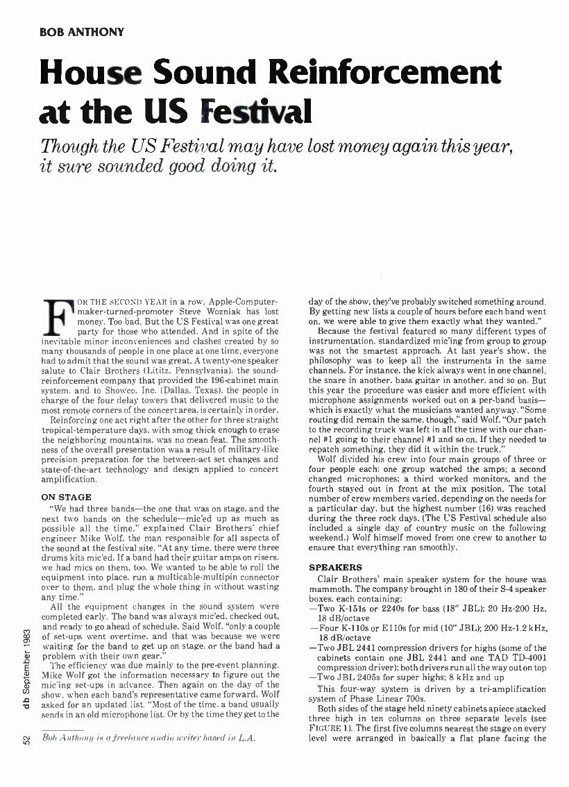
BOB ANTHONY
House Sound Reinforcement at the US Festival Though the US Festival may have lost money again this year, it sure sounded good doing it.
FOR THE SECOND YEAR in a row, Apple- Computer- maker -turned -promoter Steve Wozniak has lost money. Too bad. But the US Festival was one great party for those who attended. And in spite of the
inevitable minor inconveniences and clashes created by so many thousands of people in one place at one time, everyone had to admit that the sound was great. A twenty -one speaker salute to Clair Brothers (Lititz. Pennsylvania), the sound - reinforcement company that provided the 196 -cabinet main system, and to Showco. Inc. (Dallas, Texas), the people in charge of the four delay towers that delivered music to the most remote corners of the concert area, is certainly in order.
Reinforcing one act right after the other for three straight tropical -temperature days. with smog thick enough to erase the neighboring mountains, was no mean feat. The smooth- ness of the overall presentation was a result of military -like precision preparation for the between -act set changes and state -of- the -art technology and design applied to concert amplification.
ON STAGE "We had three bands -the one that was on stage, and the
next two bands on the schedule -mic'ed up as much as possible all the time." explained Clair Brothers' chief engineer Mike Wolf, the man responsible for all aspects of the sound at the festival site. "At any time, there were three drums kits mic'ed. If a band had their guitar amps on risers, we had tries on them, too. We wanted to be able to roll the equipment into place, run a multicable -multipin connector over to them. and plug the whole thing in without wasting any time."
All the equipment changes in the sound system were completed early. The band was always mic'ed, checked out, and ready to go ahead of schedule. Said Wolf, "only a couple of set -ups went overtime, and that was because we were waiting for the band to get up on stage, or the band had a problem with their own gear."
The efficiency was due mainly to the pre -event planning. Mike Wolf got the information necessary to figure out the mic'ing set -ups in advance. Then again on the day of the show, when each band's representative came forward, Wolf asked for an updated list. "Most of the time, a band usually sends in an old microphone list. Or by the time they get to the
CM Bob Anthony is a freelance audio writer based in L.A.
day of the show, they've probably switched something around. By getting new lists a couple of hours before each band went on, we were able to give them exactly what they wanted."
Because the festival featured so many different types of instrumentation, standardized mic'ing from group to group was not the smartest approach. At last year's show, the philosophy was to keep all the instruments in the same channels. For instance, the kick always went in one channel, the snare in another, bass guitar in another, and so on. But this year the procedure was easier and more efficient with microphone assignments worked out on a per -band basis - which is exactly what the musicians wanted anyway. "Some routing did remain the same, though," said Wolf. "Our patch to the recording truck was left in all the time with our chan- nel #1 going to their channel #1 and so on. If they needed to repatch something, they did it within the truck."
Wolf divided his crew into four main groups of three or four people each: one group watched the amps; a second changed microphones; a third worked monitors, and the fourth stayed out in front at the mix position. The total number of crew members varied, depending on the needs for a particular day, but the highest number (16) was reached during the three rock days. (The US Festival schedule also included a single day of country music on the following weekend.) Wolf himself moved from one crew to another to ensure that everything ran smoothly.
SPEAKERS Clair Brothers' main speaker system for the house was
mammoth. The company brought in 180 of their S -4 speaker boxes, each containing: -Two K -151s or 2240s for bass (18" JBL); 20 Hz -200 Hz,
18 dB /octave -Four K -110s or EllOs for mid (10" JBL); 200 Hz -1.2 kHz,
18 dB /octave -Two JBL 2441 compression drivers for highs (some of the
cabinets contain one JBL 2441 and one TAD TD -4001 compression driver); both drivers run all the way out on top
-Two JBL 2405s for super highs; 8 kHz and up This four -way system is driven by a tri- amplification
system of Phase Linear 700s. Both sides of the stage held ninety cabinets apiece stacked
three high in ten columns on three separate levels (see FIGURE 1). The first five columns nearest the stage on every level were arranged in basically a flat plane facing the

Clair S -4's 3 rows each
stacked 3
cabinets high
Scrim w /rainbow painted on front
8 proprietary long -throw transducer cabinets
L3 C7 E1 E®E] Off -stage cabinets
Diamond vision on top of stage
On -stage cabinets -I in arc
AUDIENCE
Spot light tower
Pre -show set -up
Stage backdrop
Stage (show area)
_'"-Side fills
T
)
)
r Ic IS
I- J l
House audio mix and
lights control
Monitor mix
position
4.-On -stage cabinets -+I I- Off-stage cabinets in arc
Sh 'we delay towers 600' from stage in a big arc
Spot light tower
AUDIENCE
Figure 1. Sound reinforcement set -up for the US Festival.
crowd, while the furthest five were arced to the outside to cover a greater audience area. "You have some trouble with cancellation," noted Clair's veteran audio engineer Bruce Jackson, whose latest projects have included mixing the international Bruce Springsteen -marathon tours and Stevie Nick's 1983 summer tour, "but in such a massive array it just doesn't matter. You have so many peaks and valleys in the frequency response that the overall sound evens out."
Four Phase Linear 700 amps in one rack powered a set of four cabinets. The top amp in the rack drove the highs in four cabinets (two cabinets per side); the second amp down powered the mids in four cabinets, and the third and fourth amps fed the bass (one cabinet per side).
The days were so hot that the amps needed extra cooling. The racks themselves were configured in groups of four, with a single piece of insulation material enclosing all the backs. This had a flap through which to install dry ice to cool the amplifiers. "At the last concert we used a ridiculous amount of ice," remembers Jackson, "and the vendor realized he was the only supplier. The price went up from something like $.25 to $1.25 a pound. This time we supplied our own."
On top of the S -4 arrays were 16 proprietary horn clusters driven by SAE 2600s. "The compact cabinets and horns are our own design," explained Mike Wolf, "and are meant for long -throw applications. We had four horns in each of eight
boxes on both sides of the stage with one 2600 assigned to each cabinet. It was more of an experiment than anything else. We were really happy with the way they worked out."
OUT FRONT The house -mix position (located about 150 feet from the
front of the stage and just off -axis to house right) consisted of enough equipment for two complete Clair Brothers mix systems, plus a standard Showco set -up for two groups that had requested their mixing services. A special tunnel, comprised of buried concrete pipe sections, was installed to link the house position with the backstage area. The four - foot height provided just enough room for someone to waddle from one end to the other. Although it may have been un- comfortable, it was much easier than fighting through the human sea engulfing the stage area and extending back to the delay towers about 600 feet out.
The mie splitter on stage fed three 40 -pair snakes that also ran through the tunnel. One fed Showco's console, and the other two ran into the system's main boards numbered "1" and "2" (see FIGURE 2). Except for the two acts (David Bowie and Van Halen) where Showco's board was patched into the system, all mixing took place via Clair Brothers' two custom -designed desks, which were totally independent of one another, yet linked through a master- control console

Showco console
LEGEND: Rack # I =
Rack *2 =
Rack 43 =
Rack *4 =
Rack *5 and 6 =
Rack =' =
Rack =8 =
Lighting board
Effects for Console # I
Master control (crossovers) Effects for Console #2 Various extra effects 20 dbx I60's each
More dbx 165's. 903's SAE 2500. phase linear 700
STAGE
Clair console # I
Rack
Sony portable digital PCM recorder F -1
Rack #8
Rack #7
-I LP 168 --'
Rack Clair console =
Clair console #3 Rack #6
Rack #5
LP 168 -- Slant monitor Slant monitor
TOP VIEW
Rack #3
Rack #4
Figure 2. House -mix position and set -up.
(aptly named " #3 "). Clair Brothers advisors (Bruce Jackson, Dave Kobb, and Rex Ray) were on hand to lend assistance to the bands' audio engineers and make recommendations as to the immediate conditions of the system and microphones.
The general procedure al lowed for one console to be mixing the act on stage. while the second was being adjusted for the following act that was being readied behind the backdrop. Each band's sound engineer could prepare approximately the gain and equalization settings and play with the effects rack dedicated to his console. During set changes, fine adjustments were made via a two -way communication
g system. S Even though recorded music was played through the main
speakers for the audience during set changes, the bands' . mixers could solo any instrument on a slant monitor located
aEi behind them at head level. They also were provided with a
á microphone routed through the stage monitors and sidefills. (%
Because the volume was up all the time, they could talk to .0 anyone on stage or kill the mic by simply flipping the on /off v switch.
"The talkback mic was invaluable," laughed Bruce Jackson. "We could usually never reach people on the intercom. But
3 if they ignored us using this set -up, we could yell at them
especially loud. The stage crew also had the same kind of mic communication with us, so they could yell at us, too."
The music playing between acts originated at the video truck. That division of responsibility was a contract provi- sion to coincide with the video presentations on the Diamond Vision screen above the stage. The couple of times that the audio feed wasn't coming through. Clair filled the dead air with recordings from their Sony PCM-F1 digital player.
MASTER CONTROL The master- control console ( #3) regulated the outputs from
all three consoles (Clair's #1 and #2 and Showco's) and mixed them with the various feeds, such as those for stage com- munications, feeds to and from the video truck, satellite feeds for the show sent to the Soviet Union, and lines for several tape machines.
The output from console #3 would then go to the master - output rack (rack #2), located between consoles #1 and #2 and containing the basic crossovers and graphic equalization for the house system. The entire set -up was "tweekable." The units in the master rack afforded the versatility to equalize each of the three on -stage and off -stage speaker- cabinet

Figure 3. A view of the stage during set -up.
levels on both sides of the stage independently at the low -, mid -, and high- frequency ranges. In other words, the bottom, middle and top levels of speaker cabinets each had their own unique equalization mix of low, mid and high frequencies. On -stage and off -stage sections were separately adjustable and the process was repeated on the opposite side of the stage. For example: less highs could be added at the lowest speaker level on- stage, yet simultaneously the highs on the top level could be boosted, while the second level of cabinets could remain at a nice balance somewhere between the top and bottom. That way, the people in the audience down front wouldn't be blown away by the sharp treble frequencies of the bottom row of speakers. But as the rows of speakers got higher (in height, not volume), the amount of treble coming out of those cabinets could increase to compensate for the longer distance the sound waves had to travel.
In turn, every crossover line had its own dbx 160 limiter/ compressor (20 each in racks #5 and #6) that would catch any problems created by someone overdriving a part of the system.
REMOTE REINFORCEMENT To retain the impact of the music produced on stage,
Unuson (Wozniak's production company) hired Showco to augment the main system with sound reinforcement towers that covered the back of the audience area. Their four sound towers were positioned in a perfect arc 600 feet from the stage. Because the sound traveled faster to the tower via cable than through air from the source on stage, a delay was added to match the wave fronts and send out coherent pro- gram material. For the 600 -foot distance, the delay time on their signal was set to approximately 540 msec.
Showco's four -way system contained JBL components, except for Yamaha tweeters on the high end. "Two cabinets make up our four -way, "explained Showco's engineer Donnie Kretzschmar. "One is a bass box with three JBL 15" K -140s. Another cabinet the same size contains two JBL K -120s for mid -bass, two JBL 2441 drivers for mid -range, and two Yamaha tweeters for the high end."
Crown PSA -2s powered the transducers. Two low -end cabinets ran off one mono PSA -2; a mono PSA -2 drove two low -mids (K -120); and a stereo PSA -2 powered the mid- range with one side and highs with the other. According to Kretzschmar, the wattage per tower approached 24,000 watts.
FESTIVAL ENTRANCE REINFORCEMENT Speaker manufacturer James B. Lansing (Northridge.
California) loaned Unuson additional speakers to soothe and entice the music afficionados at the main gates while they waited to filter through the ticket -takers. JBL brought in 12 (four for each of the three entrances) 4680 Line Array column speakers. The cabinets incorporate four E -110 low frequency drivers and two 2402 bullet tweeters. Because the entrances were such great distances from the stage area. the UREI model 6500 amplifiers that powered the JBL columns were fed via microwave to eliminate as much cable as possible. The sound was very good.
In fact, the whole system was a joy to hear, with clear upper end and solid bass response throughout most of the show site. But if you missed the event of the year this time around, don't feel too bad. Rumors are already circulating that Woz may try again next year. Good luck.

MICHAEL TAPES
Compact Disc Analysis Author Tapes has taken what appears to be a novel approach in investigating the CD- listening to it.
A AS
MEMBER of the professional audio community, and an avid music listener, digital audio technology is now part of my life. For the past several years I have been exposed to this magical process in the
following ways: 1. by reading the various trade publications. 2. by attending digital demonstrations, 3. by attending recording sessions, 4. by listening to digitally recorded records.
For an investigation of digital as a viable (and musical) medium, the first three items on this list could well be ignored. They were intellectually enlightening, but my brain kept calling for an information input through my ears, not my eyes. The demos and recording sessions never really lent themselves to any purpose other than hype. My brain kept telling me to get out of those situations as quickly as possible.
That leaves item 4, the final product...the record. as the only true source for my evaluation of the digital recording process. After all, if the proof of the superiority of digital recording is not on the record, then what's all the fuss about in the first place?
My quest for the truth about digital has not been my only quest for truth in audio. Since my youth, I have been involved with recorded music on many levels- first, as a musician, a hi -fi enthusiast, a hi -fi repair -person, a hi -fi salesman, then later on as a recording engineer, a concert and radio pro- ducer, a pro' audio dealer, and eventually as a pro' audio designer and manufacturer. Through it all, I have always investigated and experimented with both the recording and playback of music.
As a result of this I have owned a few hi -fi systems in my time. The first was the typical starter system of the day: an AR turntable, a Dynaco SCA -35 (built from a kit, of course), and a pair of AR -4X Speakers. My present system comprises a Linn -Sondek turntable with a Linn Itok tonearm and Linn Asak cartridge. Naim Electronics (including pre -amp, crossover, and power- amps), and Linn PMS Isobarik Speakers.
To me, the above system represents the playback system that is most capable of satisfying my two basic musical needs. First is the out -and -out emotional pleasure derived from the music listening experience; second is the ability to extract all of the information stored on the playback medium (in this case the LP record).
Without going into a complete discourse, the folks at Linn (in England) have pioneered (no pun intended) the state of the art in turntable design. While other turntable manu- facturers were building turntables that could reproduce test records with the best specs, Linn's founder, Ivor Tiefen- brun, was busy listening to music. He came to the conclusion that the specs derived by "testing" turntables had no relation to how music sounded when the record was played back. His proclamation to the world that "turntables sound different" was scoffed at. Now, some 15 years later, "high -end" turn- tables are often judged by how they compare to the Linn - Sondek, whose basic design has not changed in all these years.
Michael Tapes is the president of Sound Workshop Professional Audio Products, Inc.
So, do all of the high -tech phase -locked -loops, super servos, and LED readouts improve the quality of the music coming from the turntable? If I may answer my own question: yes and no. Some of today's super -fancy turntables are improved by hi -tech design, and some are not. This leads me to two conclusions: technology is wonderful, and, we cannot be assured that more technically complex designs will always yield more musical results.
To finish my short digression on the Linn PMS system, all of its components have been designed with musical output as the only criterion. I am convinced that it represents both an incredibly enjoyable home listening system, as well as an amazing diagnostic tool in the analysis of recorded music (and in the design and evolution of audio circuits, I might add).
THE FAULT LIES IN THE TURNTABLE In those years between my Dynaco /AR system and the
present tri- amplified Linn /Naim system, I have discovered that records are not as bad as both the public and the pro - audio community make them out to be. In fact, while record manufacturing certainly has its problems. the major prob- lem is turntable design. Records played back on the Linn turntable (as well as a few others) are simply amazing. Those of you who can't stand to listen to your old records will be pleasantly surprised at the amount of musical information and enjoyment that lurks in those old grooves. (In fact, a large amount of 10- 20- year -old records sound as good or better than today's records.) However, the bulk of the turn- tables on the market today are just not up to the task of playing back records. The manufacturers keep adding features while lowering prices, without much regard to extracting the musical information stored on the record. (Just a note: surprisingly, as a turntable's "musical" design improves, the amount of disc surface noise decreases.)
A NEW CONTENDER And now, enter the Compact Disc. The promise is wonder-
ful. Huge dynamic range due to "no" noise; convenience of use; a relatively non -destructable medium. Finally, the true performance of digital can be realized. It is interesting that those of us who have criticized the sound of "digital" record- ings have been told that the problem is that the analog record cannot handle the full dynamic range afforded by the digital master tape. This is what causes the bad sound. When the Compact Disc arrives (or so we are told), we will finally hear the "real," the wonderful, the magic of digital.
Of course, we were also told that recording engineers have been "engineering for analog" all of these years. They will now have to re -learn their trade. After all, the reason that digital recordings sound bad is that they were engineered with analog in mind. Is this true? Well, since analog records cannot let through what the Compact Disc promises, we will only find out when the Compact Disc reaches the market- place.
Well...listen up. The Compact Disc is here. As stated above, the design objectives are admirable and well- defined. All of us in the music and related equipment and service business look forward to the emergence of a system that will

excite the public to the point where the purchase of recorded music will once again be important in their lives. A medium that will encourage purchase rather than copying is also vital to our survival.
And, if the promise of sonic performance is proven correct, we shall all benefit -as listeners, with more enjoyable music in our homes, as engineers, with a better vehicle for our science and art.
However, the public may not jump at the technology all that quickly, especially after being severely burned with the promotion of quad. What is needed is a viable product that will deliver long -term satisfaction and value. Let's examine whether the Compact Disc will do this.
In investigating both the Compact Disc and peoples' attitudes toward it, I have found three prevailing attitudes: I. It is amazing. It answers all of our needs. It is musically
and technically "perfect." 2. It is musically unpure. The technology is not proven. It is
a total waste and much too early for introduction. 3. It is very exciting and important, but its musicality and
reliability (over time) is uncertain. Let's move ahead -but slowly.
THE INVESTIGATION I must confess that I entered this investigation with atti-
tude number three. My earliest experience with digital records was simply that they sounded a lot worse than analog records. However, I took on this assignment with an open mind -along with a Technics model SL-P10 Compact Disc Player.
I went to my local record store and purchased several discs. It was important to me that the material on the discs was familiar and analog (if we can have "digital" LP records, I guess that we can have "analog" Compact Discs). In this way I could better isolate the "effect" of the Compact Disc system. Yes, at that point I expected a CD "effect." By using familiar material I also planned to compare the discs to my existing LP records. Since I listen mostly to pop music, my purchases reflected this. Also, I could not find much (if any) classical music that was originally recorded analog.
This purchase of "analog" material goes against the promoters of CD. They tend to say that analog material will not show off the benefits of CD, that one must have a pure digital master in order to really enjoy CD. Well, I didn't want to enjoy CD. I wanted to enjoy music. And so I proceeded (although I did purchase some digitally recorded CDs as well).
The Technics player is high -tech, well built, and profes- sional. A button is pushed and a motorized magic door pivots toward you. I inserted a disc and the door smoothly retracted. sucking the disc inside. It was all very seductive. and I was into it. My first disc was Simon and Garfunkel's Bridge Orer Troubled Water. (The salesperson at the store said I shouldn't buy it because it was not a digital recording and there was a lot of hiss on it.)
I pressed #6 followed by PLAY. Some fluorescent readouts changed their status and moments later my analog duo were singing the strains of "The Only Living Boy in New York." I was in awe of the sound. Unbelievable. No ticks, no pops, no clicks. Just S &G. Yes, there was hiss, but it was constant and unobtrusive, and not very loud at that. I skipped around the disc (it's very easy to do) and finally I decided to do an A/B to the LP record.
It was no contest; the record lost. Even though I am ex- tremely careful with my records, poor Paul and Art were being rudely interrupted with all kinds of noise on the record, while being bathed in glorious silence on the Disc. I was converted. But now, my anti -digital bias would have to be re- directed towards the bad digital recording tech- niques of the engineers. Obviously, if CD players sounded great, the professional digital multitracks and mastering machines must be OK, too.
First impression: I had been wrong about digital all along.
All that I had come to believe was down the drain, due to the overwhelming seductive silence and convenience of the Compact Disc.
Well, several weeks have gone by. While the "new toy" aspect of the CD still exists, I have gotten over the thrill of first impressions. I have had many people to my home to listen and evaluate the CDs. I even acquired two other players to confirm or contradict the performance of the Technics. My impressions based on my experiences and the observation of others are as follows.
IMPRESSIONS OF THE HARDWARE The CD "system" is in its infancy. All three players sounded
different (contrary to the mass circulated magazine reviews). One can come to drastically different conclusions depending on which machine is auditioned. Since I had only one sample of each machine. I could not determine if these were sample - to- sample deviations or if the differences were based on the differing designs. Yes, contrary to the promotion that all of the players are the same, they go about decoding the discs differently. Some of the differences are: number of laser beams. number of D/A converters (some multiplex for left and right channels), sampling rate. filtering techniques, and so on.
The best of my players was the Technics, and that was the machine that I listened to except when comparing machines. I might add that the differences between machines were not linear. That is to say that machine A might sound better than machine B on loud passages. but B might sound better than A on low level passages. In addition, and much to my surprise. the machines also varied in their reproduction of dynamics. That is to say that each machine not only sounded different. but they also were not dynamically linear. This aspect was a complete surprise.
One of the anticipated virtues of CD is the elimination of the problems associated with the choice of cartridge /arm/ turntable combinations and their proper setup. Well, based on the variations in the three players used, we still have a long way to go. My conclusions regarding the first generation hardware is that there seems to be no way to determine the best player or to know if it is indeed working properly. The magazine reviewers are merely playing test Discs and measuring numbers. Their conclusions are that the ma- chines spec out better than analog and that they all sound great. WRONG!
LOOK MA, NO NOISE It is an amazing experience to listen to music without the
associated record noise we have come to tolerate. From a musical and artistic point of view, there is much to be said for the elimination of this garbage that is always added without the consent of the composer. artist or producer.
This elimination of noise reveals itself in an extended dynamic range that is clearly desirable in the listening experience. It is reminiscent of the days when Dolby A Noise Reduction was first introduced. However, it was incredible that we had to deal with the psychoacoustic phenomenon of no noise. At first hearing, this tends to make the material sound dull and rolled off. This also happens with the CD. The music sometimes sounds dry and disjointed due to the lack of noise. To some this is a thrill: to others it is unnerving. Have we been listening to "noise- biased" music for so long cr that when provided with a noise -free alternative it sounds
m wrong? Or does CD have its own set of problems that tend to g make the music sound unnatural? I say YES...to both. 3 If we look at professional audio engineers, we see that cr many of them are not using noise reduction as often as before. `D
having mostly decided that the benefits of Dolby and dbx are more than offset by audible side effects. w
This no doubt will be repeated with the CD experience. Almost everyone will be knocked over by the lack of noise and the convenience of operation, and many may temporarily ignore any sonic side effects of the digital process. Also -and

co
not yet fully addressed -is the question of implementing precision technology in a mass -produced box that is targeted for the lowest possible cost.
THE MUSIC PROBLEM If we can separate ourselves from the luxury of a relatively
noise -free source. we will see that the music (remember that ?)
truly suffers in the CD environment. Music loses its ability to compel the listener. What is reproduced is a series of noises that our brain translates into what we know should be music. No one would argue that listening to a $50 phonograph is awful, yet the brain can still translate the noise into music. It's not necessarily a satisfying musical experience, but we still know that that distorted mess is music. CD yields high - fidelity noise compared to the $50 special, but it is the con- clusion of myself and many others that the critical informa- tion that makes the high- fidelity noise into a satisfying musical experience has been stripped away by digital and specifically by the CD process.
Many will disagree and will have satisfying musical experiences with CD, at least in the short run. For many, CD will be such a step up from inadequate (but maybe expensive) turntables that they will be thrilled beyond their wildest dreams, not realizing that a properly designed turntable would probably be even more satisfying in the long run.
There can be no dispute that records have a tremendous potential for damage over time. The CD has much less of a chance for damage. On several occasions in my usage a seemly trivial fingerprint has affected the CD playback. On one occasion a fingerprinted disc coughed, clicked. popped and muted in one machine, wouldn't even begin to play in another machine, while in the third it played, seem- ingly unaware of the presence of the print. When wiped off, the CD played properly in all three machines. Assuming
the musical content is indeed on the disc, the CD (even at its $20 price) seems like a good longterm investment in terms of the physical medium. If indeed the musical content is not intact, then we have purchased archival noise.
IN CONCLUSION So what's a mother to do ? ?? For me, it's wait and see. I would love to see the CD come
into its own and provide the full spectrum that it promises to offer. It is not here today. Should one run out and buy a CD player? It depends. Those of us who are techno- freaks and want to know and learn the truth about new technologies firsthand should buy one. Those who want the convenience and silence that the CD offers should buy one. Those music listeners who only want the best possible musical reproduc- tion in their homes will not be satisfied with today's CD.
And what of the engineering community? Have we all the while been putting out bad sound product that is now dis- covered to be unacceptable in the digital domain? Sure we have...but we have also put out great- sounding music. Do we need to review our recording techniques? Of course we do. But competent artists in all fields of endeavor stop and review every so often. If CD and the digital recording processes force us to examine whether other parts of the recording chain (consoles included!) are up to their musical limits, then great. But let us not look over the newest tech- nologies (digital) and think that they are unerring due to their fresh and seductive virtues. Let us evaluate the entire recording and listening chain.
I for one will continue to research and evaluate CD, be- cause if we can overcome its problems it will benefit us all - both artistically and financially.
Now if you will excuse me, it's time for the yearly replace- ment of my stylus.
I cYcu INQWWH E RE? Have you mis placed your db again? Our high quality, royal blue vinyl binders keep 12 copies of db neat and handy for ready reference.
Just $9,95, available in North America only. (Payable in U.S. currency drawn on U.S. banks.) ORDER YOURS NOW!!
rSagamore Publishing Co., Inc. 1120 Old Country Road
I
Plainview, NY 11803
I YES! Please send db binders I @ $9.95 each, plus applicable sales tax. I Total amount enclosed $
í1
Name
Company
I Address
I City
State /Zip

spun SOCIETY OF PROFESSIONAL
AUDIO RECORDING STUDIOS
or 1 Dedicated To Excel ence Through Innovation Educorion Communcation
VOLUME 3, NUMBER 3 JULY /AUGUST /SEPTEMBER
r PRESIDENTS MESSAGE
"THE PULSE QUICKENS"
Mack Fineman
SPARS at this time is broadening its horizons as never before. Our membership continues to grow, which is most rewarding. The course we must logically follow becomes more apparent.
The video post production "familiarization" seminar which was held in Chicago on Saturday, August 5, was most enlightening to all participants, thanks to the generosity of Editel and SPARS Vice President Len Pearlman.
At our meeting in Chicago, the SPARS Board of Directors made the decision to realign our administration to better serve the organization for the many aibitious programs that are about to be undertaken.
I am pleased to announce that Gary Helmets, who has done such an admirable job as West Coast Coordinator, has been given the job of Executive Director of our organization starting November 1, 1983.
David Teig's position as New York Coordinator will stay as is, and well it should in recognition of the mighty contribution that Date continually makes. We couldn't do it without you, Dave.
Nick Colleran will remain our Treasurer and Dannie Emernran will assume the position of "Corporate Secretary ".
Our committee reports during the board meeting point to putting into place the "SPARS EXAM" by January 1984, as well as many other innovative programs soon to be announced.
On Monday, October 10 in New York, SPARS will interface with the Audio Engi- neering Society to sponsor a workshop on "The Business of Studios."
Our general membership meeting and installation of new officers will be coincident with the SMPTE Convention in Los Angeles the first week in November.
The nominating committee has posted the names of those nominated for officers and board of directors for the 1983 -84 fiscal year. They can be found on another page of Data Track. I would like to congratulate the committee for their careful considera- tion of the many choices. I am personally most pleased with the slate as presented. There are old names, new names, old blood, new blood ... a super combination that I
know will do a great job next year. They will make my tenure as chairman of the board even more exciting than my year as president, which I can't believe is almost over.
A special thanks to db Magazine for printing this issue of Data Track as part of their AES issue. We appreciate the support of db Magazine and the valuable assistance and counsel of editor John Woram.
I would like to take this opportunity to thank the Board of Directors and Past
Presidents who have worked so closely with me, for their unfailing support. I will look forward to being as actively involved as possible in the coming years, because as l'In sure you know, I believe in this organization and that it will continue to educate and
bring together the many diverse elements of our ever growing and changing industry.
THE TRUTH BEHIND
THE BLUE SKY HEADLINES
By Ruth A. Robinson Music Editor
The Hollywood Reporter
As early as the end of 1982, reports began to be circulated and end up in print that the music business was about to jump back on its rocket ride to moneyland.
Of course, that was about the same
time that the propaganda mills were churning out the news that the country's economy was back at full tilt. The bard reality is that neither the country nor the music industry is fully recovered, although our business is looking up.
But certain moves need to be made to ensure its continued growth, even if it is
not a rocket ride. The records that are
selling now were recorded a while back. Often they were cut at reduced rates in recording studios hungry for any business at all, when poised on the brink of bank- ruptcy or oblivion. Many, many studio owners are nervous.
The labels need to sign new acts .. .
aggressively and not rely on inventories. Those new signings filter down to the ser-
vice industries ....the recording studios and instrument rentals . . . they create some excitement at the radio levels and give the consumer something new to bend their ears to.
Companies need to adopt a truly posi- tive stance on the Compact Disc ... all those who hesitate might end up with vinyl on your faces.
I don't know what happened to tour support from labels. It seems strange to me still to see a camera company sinking millions into Barry Manilow's tours or the beer company ringing up dollars from Men at Work concerts.
l'In enjoying listening to the radio again after a while of being bored to
continued next page

o co
BLUE SKY continued from previous page tears. On the other hand, if there were more deals cut, more music out there, there'd be even more to get happy over and it just might put some grins on the faces of recording studio owners and
instrumental rental companies . maybe even some limousine companies. Heaven forbid that we ever get prosperous enough that people start sending me T- shirts and pins and buttons and posters and satin jackets ...
TO ALL SPARS MEMBERS BOARD OF DIRECTORS NOM /NATIONS 1983.84
JERRY BARNES -PRESIDENT
Since 1972 Jerry Barnes has been Vice President of Recording for United Record- ing Corporation (a div. of Harman Inter- national) and General Manager of United/ Western Studios in Hollywood CA. He has also served two terms as regional Vice President of SPARS and sits on its board of directors.
Jerry Barnes' career in audio record- ing covers a span of thirty years. His in- troduction to "making records" came when he and a group of high school bud- dies pooled their resources and purchased a primitive disc recording system. Barnes recalls that the device was portable and he and his friends utilized a neighbor's hay loft as their recording studio. "Since we didn't know better, the loft was as good a place as any to begin our assault upon the outside world. The main prob- lem was to avoid stepping in anything soft on the way to the hay loft and now that 1 think about it, not much has changed... I'm still in this business because I don't know any better and I'm still trying to keep from `stepping in anything soft'."
The early fascination with sound re- cording grew into pre -occupation during undergraduate days at Baylor University and in the years following. "I was one
of the early recording artists for WORD records and naturally I wanted my albums to sound as good as the ones being made by the superstars of the day. It seemed to me most of the really great sounding records were being made in Chicago and engineered by a guy named Bill Putnam at his studio called Universal.
No one in the south could come close to getting as much sound on a disc as Putnam so ... my goal became fixed. I
wanted to record an album in Chicago with Bill Putnam. After a year or two, I
finally arrived there only to find that Putnam had departed for the West Coast so I was stuck with a young unknown mixer with a funny name ... Bruce Swe- dien. He told me that he was a protege of Putnam so I gave him a shot. Bruce did good. 1 think he is still around. After ob- serving how easy Bruce made it look I
couldn't resist following the desire to make a career change and move to the other side of the glass. With role models like Putnam and Swedien I set out on the course that led me to where I am today. Happily, Swedien is a great friend and Bill Putnam, after having been my mentor for nearly fifteen years, is closer than a
brother." Today Jerry Barnes is a respected lead-
er in the recording studio industry, a successful audio engineer, a published author and a speaker much in demand by academic and service institutions throughout the country.
C. NICHOLAS COLLERAN,.JR. SECRETARY TREASURER
Nick Colleran founded Alpha Audio of Richmond, Virginia in 1971. He brought to Alpha Audio his experience as a CPA (B.S. in Commerce from the University of Virginia and work experience with
DATA TRACK is published by The Society of Professional Audio Recording Studios.
Editor: Gary Helmers Please send all news and comments to Editor, SPARS, P.O. Box 11333, Beverly Hills, CA 90213
A.M. Pullen & Co.) and as an artist, writer and producer signed with CBS Records. At Alpha he has engineered for almost all the major record labels and has produced for several.
Today Nick is involved full time with the management of Alpha Audio (five recording studios); a full time in -house jingle and scoring production com- pany (Candyapple); a professional audio sales and service company; and nation- wide distribution of acoustic materials from warehouses in Richmond and Minneapolis.
Recent projects include: from the studio - Snuff on Warner Brothers Records (#93 with a bullet, 8/15); at Candyapple - production of a live stage show for Reynolds Metals; the audio equipment company - Richmond Symphony Concert Hall; and acoustic materials going everywhere!
Mr. Colleran has served on the Board of Directors of SPARS for 3 years as a
regional Vice President and Treasurer.
BOB LIFTIN VICE PRESIDENT- EASTERN
Bob Liftin's success in the audio in- dustry stems from a unique and sensitive ability to read the tides of the future with an unquenchable thirst for knowledge and a constant driving desire for advance- ment. Today, owner /president of Regent Sound Studios, New York, Bob Liftin be- lieves we have entered the most rapidly

advancing and most challenging times for electronic innovation, and computer con- trolled accuracy and speed as well as a
new era in the presentation of entertain- ment. The audio medium is by- passing its former limitations of dynamic range, re-
productive quality and transmission abil- ity. The linking together of the audio and visual experience will lead to new levels of artistic expression.
Beginning at the age of seventeen he was an assistant engineer and maintenance technician at Allegro Sound Studios, New York. At eighteen while still attending the City College of New York with a ma- jor in physics, he worked for CBS where he gained his experience in live broad- casting as a maintenance technician. In 1958 at the age of twenty -one Bob Lif- tin opened Regent Sound Studios record- ing, mixing and mastering records. In 1973 Regent Sound Studios pioneered the syn- chronization of two multitrack audio ma- chines. By 1975 video was added and complete electronic editing and synchron- ization of film, video and audio in all for- mats was achieved by 1979. Presently a
four studio recording and audio post -pro- duction facility, Regent Sound Studios services the record, advertising, television broadcast and film industries.
Bob Liftin spends an average of 10 hours per day behind the console as a re- cording and mixing engineer as well as
maintaining an active schedule doing loca- tion recording and post -production on a
variety of T.V. music specials. He is Audio Consultant for "Saturday Night Live" and has held that position for eight years. Bob is also chief audio consultant and main line mixer for the MDA labor day tele- thon; as well as The Tony Awards.
CHARLES M. BENANTY VICE -PRESIDENT- EASTERN
Charles M. Benanty established Sound Works Digital Audio /Video Studios in New York in 1978. Mr. Benanty was a founding member of SPARS and has served on the Board of Directors as Eastern Vice- Presi- dent for one year.
LEN PEARLMAN VICE PRESIDENT- CENTRAL
Lenard Pearlman is currently Vice President of Technical Services for Editel- Chicago. Over the past ten years Len has held both engineering and management positions. He has been responsible for not only the technical direction, but the design and construction of the Chicago facilities
continued next page
EXCELLENCE THROUGH INNOVATION!
The SPARS regional meetings examine a variety of topics of interest and value to the audio recording industry. The topics range from immediate maintenance prob- lems to future concerns, such as the role audio recording studios will play in inter- active video. Through teleconferencing,
any studio in the country can participate in these meetings. Participation is increas- ing constantly and we welcome all inquiries regarding involvement in the regional meetings.
For further information, contact any SPARS office.
EXCELLENCE THROUGH EDUCATION!
The SPARS thrust into the field of education is moving forward on several levels. Our interfaces with students at the University of Miami and the University of Colorado at Denver were productive and beneficial for the students and also the professionals that participated.
SPARS has initiated a pilot program to provide internship experience for stu- dents in the audio engineering field. Students have been grateful for the expo- sure to the real world of the recording industry and the studios value these initial contacts with the individuals who will be their employees of the future.
Larry Boden, of the JVC Cutting Center, is progressing rapidly with the development of the SPARS Certification Exam. This test will provide a common denominator for evaluating potential
employees from a variety of educational and experiential backgrounds. Any input that professionals in the field of audio engineering can provide is solicited. Write five multiple choice questions today and send them to any SPARS office! We'll see that they get to Larry.
The Digital Education Program is our educational thrust on the consumer level. We are concerned that the acceptance of digital technology might be impeded by a
lack of understanding by the consumer. The transition to digital technology will require an unprecedented amount of cooperation within our industry. The Society of Professional Audio Recording Studios is working to insure cooperation between record labels, hardware manu- facturers, software producers and record retailers.
EXCELLENCE THROUGH COMMUNICATION!
Thanks to db Magazine, Pro Sound News, Mix Magazine and REP for their assistance in presenting the DataLine program to the audio recording industry. The letter below is but one example of the gratifying response we have received. At some time, some place, someone in SPARS has faced the problem you may be facing today. Let us help!
April 25, 1983 Dear SPARS,
When Bob and I saw the announce- ment for the new DataLine, it appeared at a time we needed some information about the business operations of record- ing studios. With one phone call to Data - Line we quickly received answers or options for all of our questions. These answers, we are convinced, have saved us
from making costly mistakes and will add to the income of our studio.
Please extend our sincere appreciation to SPARS for providing this service. Thank you for your time, courtesy and genuine willingness to help.
Yours, Mary Curlee Business Manager Strawberry Jamm West Columbia, South Carolina
Questions regarding any area of record- ing studio operations including business, audio engineering and technical mainten- ance will be answered by SPARS -approved sources at no charge.
Want a problem solved? ... call SPARS -(305) 443 -0686. rn

NOMINATIONS continued from previous page
as well. Prior to Editel, Len held produc- tion positions for both ABC and PBS af- filiates, and worked in the Chicago Re- cording Industry. He has recently been elected as a manager of the Chicago chap- ter of the SMPTE.
JOHNNY ROSEN VICE PRESIDENT- CENTRAL
Johnny Rosen is the president of Fanta Professional Services, Nashville, Tenn., which specializes in mobile recording for the entertainment industry. Fanta's clients include all four major television networks, several major film companies, radio net- works and syndicators, and most major record labels. Mr. Rosen has received film credits for his work on Robert Altman's "Nashville ", "Coal Miner's Daughter ", and "The Blues Brothers ". Additional credits include approximately 250 audio projects such as audio /video fusions for the opera "A Bayou Legend" for the Pub- lic Broadcasting Service. Mr. Rosen's con- sulting projects have included noise con- trol in industrial situations, numerous re- cording studio specifications, and work for the White House Communications Corps. Mr. Rosen attended Rollins Col- lege in Winter Park, Florida where he concentrated in English and electronic media. He is currently an adjunct pro- fessor of music at the Blair School of Music at Vanderbilt University and has been a guest lecturer at several universi- ties in the United States. Actively in- volved in the Audio Engineering Society since 1968, he has been committeeman, chairman, treasurer of the Nashville section and is now serving on the board of governors of A.E.S. as the central region vice -president. Mr. Rosen has presented papers at A.E.S. conventions dealing with new approaches to motion picture sound and has written articles for Studio Sound and Pro Sound News. He has lectured at the national meeting of SPARS. Current- ly, Johnny is the Nashville Vice- President of SPARS. He is also a member of the National Academy of Recording Arts and
"GRAMMY" RECOGNITION FOR STUDIO PARTICIPATION
The National Trustees of NARAS (Na- tional Academy of Recording Arts & Sci- ences) have voted to create a plaque or similar form of acknowledgement to re- cording studios who have participated on Grammy -winning recordings. The partici- pation-confirmation will indicate the title, artist and category of the Grammy -win- ning recording, along with the name of
the studio. As soon as details have been finalized the plaques will be available to all eligible studios at a cost to be deter- mined.
SPARS Past President and NARAS National Trustee Murray Allen, was instru- mental in the creation of this acknowledge- ment of studio participation on Grammy - winning recordings.
Sciences, the Country Music Association, and is an elected board member of the Nashville Music Association serving as
chairman of the studio division. Also, Mr. Rosen is serving his second three year term on the board of the Nashville Sym- phony. Notable recording projects range from the Rolling Stones to the Philadel- phia Symphony Orchestra.
LARRY BODEN VICE PRESIDENT -WESTERN
Larry Boden is a native of Pittsburgh, Penn. He received a Bachelor of Fine Arts degree from the Conservatory of Music at the University of Cincinnati in 1969. He is
currently chief engineer of the JVC Cut- ting Center in Hollywood, Calif., and has been in that position since early 1980. He has been employed previously by MCA Records in Los Angeles; National Record Productions, Nashville; and Rite Records in Cincinnati. As a mastering engineer, some of his credits include Crystal Gayle "Don't It Make My Brown Eyes Blue," Don Williams, The Who, Grandfunk Rail- road, soundtracks from many movies in- cluding "Smokey and the Bandit ", "Am- erican Graffiti" and others. He is an active writer on both disc mastering and digital subjects. His articles have appeared in The Mix, International Musician, and Record- ing World and other publications.
BRUCE BOTNICK VICE PRESIDENT - EASTERN
Bruce Botnick began his career in audio at Liberty Records Recording Studios as an engineer. His projects in the early 60's included: The Chipmunks, BobbyVee, The Fleetwoods, The Ventures, Jan & Dean, Jackie DeShannon and Leon Russell.
From Liberty Records, he moved to Sunset Sound Recorders in 1963 to con- tinue as an engineer and adding the roles of producer and studio manager. Bruce's projects at Sunset included such diverse talents as Love, The Doors, Randy New- man, Marvin Gaye, Claudine Longet and Little Stevie Wonder.
In 1968, Mr. Botnick began a three year tenure with Elektra Records as engineer, producer and studio manager. His client list
grew to include: The Rolling Stones, Dave Mason, Delaney & Bonnie, Judy Collins, Janis Joplin, Santana and many others.
After becoming an independent engi- neer, Botnick won a Grammy Award in 1972 for "Best Spoken Word Recording" as the producer of "Lenny," the first Broadway play recorded live on stage. The list of artists continued to grow - Helen Reddy, Mac Davis and Earth, Wind and Fire. 1975 brought a contract as Ex- ecutive Producer with CBS Records and more artists -Les Dudek, Jerry Goldsmith, Eddie Money, Kenny Loggins and produc- tion of the soundtrack LP for Star Trek. In 1981 Bruce produced the Grammy Award winning recording ( "Best Male Pop Vocal ") of Kenny Loggins "This Is It" from the "Alive" LP.
Today Mr. Botnick is an independent engineer for Bruce Botnick Productions, Inc. and President of Digital Magnetics, Inc. Recent projects include production of the music for "Twilight Zone," "Un- der Fire" (an Orion film to be released September, music featuring Pat Metheny) and the new Sean Connery -James Bond feature "Never Say Never."
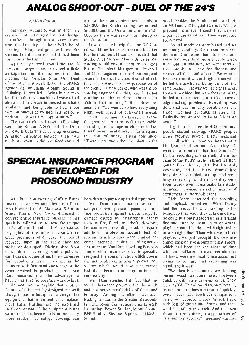
ANALOG SHOOT -OUT - DUEL OF THE 24'S by Ken Easton
Saturday, August 6, was another in a
series of hot and muggy days that Chicago has suffered through this summer. It was also the last day of the SPARS board meeting. Things had gone well and the various board members felt it had been well worth the trip and time.
As the day moved toward the late af- ternoon, everyone began to feel a little anticipation for the last event of the meeting -the "Analog Shoot- Out -Duel of the 24s," as it was billed on the SPARS agenda. As Joe Tarsia of Sigma Sound in Philadelphia recalled, "Being in the mar- ket for multi -track machines, I was excited about it. l'm always interested in what's available, and being able to hear these two machines, side by side, in direct com- parison ... it was a real opportunity."
The two machines Joe was referencing were the Studer A -800 and the Otani MTR- 90 -11, both 24 -track analog recorders. A major difference between these two machines, even to the untrained eye and
car, or the nontechnical mind, is about 525,000 -the Studer selling for around S65,000 and the Otario for close to $40,- 000. So there was reason for interest in the shoot -out.
It was decided early that the OK Cor- ral would not be an appropriate location for the shoot -out. It was also decided that Studio A of Murray Allen's Universal Re- cording would be quite appropriate. Rich Breen, Technical Manager at Universal and Chief Engineer for the shoot-out, and several others put a good deal of effort, time and energy into the preparation of the event. "Danny Leake, who was the re- cording engineer for this, and I started working on the machines about eight o'clock that morning," Rich Breen re- members. "We wanted to have everything ready well ahead of everyone's arrival.
"Both machines were biased ... every- thing was set up to be as flat as possible, according to the tape machine manufac- turers' recommendations, as far as eq and that sort of thing," Breen continued. "There were two other machines in the
SPECIAL INSURANCE PROGRAM DEVELOPED FOR
PROSOUND INDUSTRY
At a luncheon meeting of White Plains Insurance Underwriters, Henri van Dam, Vice President of A. Matarasso & Co. in White Plains, New York, discussed a
comprehensive insurance package he has
specially tailored to address the unique needs of the Sound and Video studio. Highlights of this unusual program in- clude provisions which cover the loss of recorded tapes in the event they are
stolen or destroyed. Distinguished from conventional recording studio policies, van Dam's package offers bailee coverage for recorded material. To those in the industry with first hand knowledge of the costs involved in producing tapes, van Dam remarked that the advantage to having this specific coverage was obvious.
He went on the explain that another feature of this carefully designed and well thought out offering is coverage for equipment that is insured on a replace- ment basis. Furthermore, he explained to those present, if the equipment is not worth replacing because it is outmoded by more modern technology, coverage can
be written to pay for upgraded equipment. Van Dam noted that conventional
comprehensive policies generally pro- vide protection against serious property damage caused by catastrophic events such as fire, flood, and theft. However, he continued, recording studios require additional protection against loss of income which occurs when studios be-
come untenable causing recording activi- ties to cease. Van Dam is writing Business Interruption Insurance that is specially designed for sound studios which covers the net profit continuing expenses, and salaries which would have been earned had there been no interruption in busi- ness activity.
Van Dam stressed the fact that his special insurance program fits the needs and distinctive peculiarities of the sound industry. Among his clients are such leading studios in the Greater Metropoli- tan and lower Connecticut area as A &R Recording, Power Station, Minot Sound, P &P Studios, Skyline, Squires, and Media Sound.
booth besides the Studor and the Otani, an MCI and a 3M digital 32- track. We also prepped them, even though they weren't a part of the shoot-out. They were more for control.
"So, all machines were biased and set
up pretty carefully. Reps from both Stu- der and Otani were there to make sure everything was done properly ... to check it all out. In addition, we went through the console to check for flatness and source; all that kind of stuff. We wanted to make sure it was just right. Then when he fed the machines, Danny came off the same busses. That way we had eight tracks, to each machine that were the same. Also, he fed to the center eight tracks, to avoid edge -tracking problems. Everything was done that was humanly possible to make those machines as equal as could be. Basically, we wanted to be as fair as we could."
It got to be close to 4:00 p.m. and people started arriving. SPARS people, other industry people, a few musicians . . . all with a common interest -the Otani /Studer shoot -out. And they all wanted to fit into the booth of Studio A! In the recording studio itself, the musi- cians of the rhythm section (Bruce Gaitsch, guitar; Bob Livzick, bass; Pat Leonard, keyboard; and Jim Hines, drums) had long since assembled, set up, and were busy rehearsing for the tracks they were soon to lay down. These really fine studio musicians provided an extra measure of excitement to the whole event.
Rich Breen described the recording and playback procedure. "When Danny laid the tracks, he was listening to the busses, so that when the tracks came back, he could just put his faders up in a straight line and listen to them. In other words, playback could be done with eight faders in a straight line. Then what we did, on playback, we just brought the two ma- chines back on two groups of eight faders, which had been checked ahead of time with an oscillator, to make certain that all levels were identical. Once again, just trying to be sure that everything was equal, and it was!
"We then bussed out to two listening busses, which we could switch between quickly, with identical electronics. They were A /B'd. This allowed us, on playback, to run the machines together and quickly switch back and forth for comparison. First, we recorded a rock 'n' roll track with lots of guitar and drums, and then we did a solo piano track. And that was
about it. From there, it was a matter of listening to playback." continued next page

ElSTUDIO TRACKS
SOUNDSHOP RECORDING STUDIOS
NASHVILLE Producer Ron Chancey was in working on sonic McDonald's commercials with Les
Ladd engineering. The Jimmy Sturr Polka Band were in cutting their new album. Tom Pick engineered. RCA artist Leon Everette cut his latest with producer Ronnie Dean. Mike Bradley
at the board. Buddy Killen was in producing Ronnie McDowell for CBS. Ernie Winfrey behind
the board. Larry Gatlin & the Gatlin Brothers worked on a project with Larry Gatlin produc-
ing. Stan Dacus and Mike Bradley engineered. Sawyer Brown worked on a few sides with J.C. Meyer producing along with Mike
Bradley. Bradley also engineered. Val & Bertie did some song demos with Travis Turk engineering. CBS artist Chet Atkins did string overdubs with Ernie Winfrey engineering. BBD & O, Detroit, came to Nashville to work on a national campaign jingle for
Dodge. Producing was Craig Deitschmann. Mike Bradley engineered. Artist Leon Raines was in with producers Milton Brown and Steve Dorff. Travis
Turk engineered.
CRITERIA RECORDING STUDIOS MIAMI
Recording their sixth album at Criteria Recording Studios in Miami is Firefall on Atlantic Records. Producing the album in Criteria's Studio E are Ron and Howard Albert of Fat Albert Productions. Patrice Carroll Levinsohn is the assistant engineer.
Out of the Criteria Cutting Center comes Hey, the second single release from the album Julio, by international recording star, Julio Iglesias. Mike Fuller mastered the disc which appears on CBS International Records.
Mixing is being completed on a "live" double album by Julio Iglesias at Criteria Recording Studios in Miami. Producer Ramon Arcusa is working on shows taped in Paris, Tokyo and London. Bob Castle is engineering. The album will be released on CBS International Records.
A new arrival to Criteria's East Wing studio is artist Mink de Ville on Atlantic Records. Producing the album are Ron and Howard Albert of Fat Albert Productions. Patrice Carroll Levinsohn is the engineering assistant.
Please include SPARS on your press list!
SPARS President Mac lanermai, President Emeritus Joseph Tarsia and Eastern Coordin- ator David Teig listen for a difference.
SHOOT OUT continued from previous page
And playback they did, for at least an hour -and -a -half. Over and over, they A /B'd dozens of times. Different people wanted to hear different things. So, they would solo -out special tracks, like the kick and snare of the drum tracks, and they'd A/B that several times. Then someone would request to hear the solo piano once again, and heads would angle so that straining ears would have a better shot at the moni- tors. Among the 20 -or -so people in the crowded booth, and the rest who spilled into the adjacent room, the hall and the studio itself, questions were being asked like, "Well, what do you think ?" "Can you hear a difference ?" "What else can
we solo -out so we can really test every- thing?" And on it went.
And what were the results, if any? As Rich Breen put it. "My impression was that the two machines were extreme- ly close. The only difference, and this wasn't a big surprise, was in the low end. The Otani starts to roll off about 10 Hz above where the Studer begins to roll off. What was surprising was that there was virtually no difference in noise between the two. I didn't hear any strange modu- lation noise on either the Otani or the Studer. Whatever the differences, and I'm not sure you'd notice any of them outside of an A/B situation, whichever machine is
best is a matter of choice. I'd be real hard pressed to pick a winner."
The keyboard player on the session. Pat Leonard, was a little more inclined toward one side. He commented, "1 really like what the Otario did in the midrange of the piano. It seemed to open it up and gave it warmth. I'm not saying that it changed the piano sound. The Otani just made the piano sound more like how I
think a piano should sound. It's funny, all my career it's been Studer. Now, I'm hearing some competition." Drummer Jim Hines was standing by and added, "Tone doesn't mean that much to me. My ears aren't trained for that. Me . .
I hear the highs and lows. For what it's worth, I really couldn't tell the difference between the two machines."
But what were the thoughts of some of the SPARS people present? Once again, Joe Tarsia of Sigma Sound: "I think that the real success of the shoot -out was that it was demonstrated that the companies who are producing professional audio machines are doing such a good job that we did have a very difficult time hearing any difference. On the other hand, had I
been running the test, I would have wanted to compare each machine to the live per- formance, also. I just think it would have been better to compare the input to the machines (the live performance) to the output (A /B). That way you're compar- ing each machine to the original sound. If one machine sounds brighter, or fatter, it might not be fair to say it sounds bet- ter, if it doesn't sound like the original."
Tarsia continued, "A shoot -out like this one leaves a lot of questions un- answered. Now, I realize that this shoot - out was intended only to test audio per - fonnance. I think it would be a mistake to say one machine is a winner and the other's a loser. You have to consider other things like overall performance, reliability, durability, and many more factors. While it was very difficult to tell a difference between the two machines, I don't think anyone should buy an expensive piece of
equipment because of the results of a
shoot -out. You should be looking for a
lot of answers, and if you're not getting the answers, ask the questions."
Mack Emerman of Miami's Criteria Studios had this to add, "The shoot -out was fun. It was interesting. People got certain impressions. There were a lot of variables that obviously came into play, and whatever we heard there really isn't the last word. I also wish we had been
able to compare the A/B with the live source.
"We certainly had our impressions, but I don't think anyone in the SPARS organ- ization would live or die by those impres- sions. There's a lot that goes into why you buy a tape machine. There are all sorts of
cases you can make for sound impressions. One person might hear smearing on one machine, another might feel the other machine is more open. To my ears the MCI sounded, almost imperceptibly, more open. Then someone else will come along who has no idea of what `smearing' or `open' means. The differences are so
subtle that they are almost insignificant. "Otani, Studer, MCI ... these people
make fine products, and I think you would see a wide variety in use across the SPARS community. We're all looking for something different. It's a matter of taste. We're all owners of service organizations and it's probably better for us to offer a
diverse line of equipment to satisfy all of those different tastes."
And finally, Murray Allen of Chicago's Universal Recording was overheard to comment, "Obviously, we're all going to get asked a lot of questions about what went on here today. Everybody heard many different things in the room. It seems to me, in the final analysis, the choice of a tape recorder is pretty much personal opinion. That is, as to what sort of a sound you would like to hear. It's really personal choice."
About the author - Ken Easton is a free lance writer, and has been a professional musician for nearly 30 years. He is presently producing and directing an industrial film starring former football great Gale Sayers.
ATTENTION STUDIO ADMINISTRATORS
SPARS wishes to remind you of the importance of having a voice in the audio recording industry as a member of the Society of Professional Audio Recording Studios. Becoming a
member is simple, inexpensive and a good investment. Dues are attractively low - as little as
51.00 a day - and the rewards of education and communication far exceed the dollars invested. We invite you to attend our Hospitality Suite in the Warwick Hotel, during the AES con-
vention, to discuss the concerns of our industry and how SPARS is addressing these concerns. If you desire more information regarding SPARS, circle #50 on the Reader Service Card. If you would like to become a member of SPARS, complete the membership application below and
send it in today! CIRCLE 50 ON THE READER SERVICE CARD
NAMML
COMPANY
ADDRESS
APPLICATION FOR MEMBERSHIP TO SPARS TITLE
PHONE
CITY STATE ZIP
REGULAR MEMBERSHIP $365 Any professional recording, mixing or mastering facility with gross billings under $1 million.
SUSTAINING MEMBERSHIP $1000 Any professional recording, mixing, or mastering facility with gross billings over $1 million, or others grossing under $1 million who wish to contribute to our growth.
ADVISORY MEMBERSHIP $2500 Includes any company presently engaged in providing services and /or supplies for the recording in- dustry, not qualified for membership in any of the preceding categories.
ASSOCIATE MEMBERSHIP $250 Includes any company or individual presently engaged in or utilizing the services of the recording industry, not qualified for membership in any of the preceding categories.
Accompanying this application is a check in the amount of S covering membership dues for the fiscal year. MAIL TO: SPARS, P.O. BOX 1060, COCONUT GROVE, FL 33133
8
SPARS (NATIONAL
ArREGIONAL UPDATE
NY UPDATE A series of nine New York Regional
luncheons have been scheduled for 1983- 84, most of which will be held at Gal - laghers Restaurant. The dates are: Sep- tember 28, October 26, November 30, January 18, February a 22, March 28, April 25, May 30 and June 27.
Bob Ludwig of Masterdisc will be the guest on September 28 and will explain in detail the preparation of a CD master- ing tape and will present other manufac- turing information about the Compact Disc.
On October 26, Henri van Darn of
A. Matarosso & Company will return to a SPARS luncheon and give studio owners an Employee Benefit Seminar dealing with IRA, Keogh, pensions, deferred compensation plans and em- ployee agreements.
On November 30, interactive video will be explained and demonstrated by Frank Dobbins of Editel- Washington, D.C., an expert in the field. A discussion will be held regarding the role audio recording studios will play in this new technology.
Watch future Data Track issues for additional topics and guest speakers.
CHICAGO UPDATE
On Saturday, August 6, Editel- Chicago hosted a seminar for SPARS members on the videotape post- production process. Attending with the local SPARS member studios were members of the SPARS
Board of Directors and many of the manufacturers who serve as advisory members.
Pete Jannotta of Editel explained the film to tape process and demonstrated the latest trend of transferring the nega- tive film elements on the Bosch Scanner. Computerized videotape editorial was demonstrated by Tom Evans, and the use of digital video effects to add electronic opticals were shown to the group. Scott Thomson showed examples of multi- track audio techniques for the improve- ment of audio for video on segments from the nationally syndicated show "Celebrity Showcase ". Len Pearlman, Vice President of Technical Services for Editel, discussed the latest trends in post production and showed examples of some of Editel's recent projects. Sony's Beta - HiFi consumer VCR was also demon- strated along with its latest video music software. The seminar provided a forum for education and discussion as many common topics were discussed during the day's seminar.
SPARS Board of Directors and Administrative Staff (305) 443.0686
Chairman Fmentus Joseph D. Tarsia Sigma Sound Studios Phddelphia
Ea -Officio Murray R. Allen Universal Recording Corporation Chicago
Chairman of the Board Christopher Stone Record Plant. Inc. Los J n«les
President Mack Emcmun Criteria Recording Miami
First Vitt President Guy Costa Jloronv /lRtsvdle (S.4 Los .Angeles
Vice PresideniSeeretary Leroy Friedman Columbia Recording Studios New York
Treasurer Nick Coleran .alpha .Audi Richmond
Regional Vice President lefty L piled M'estern Studios Lost ngeles
Regional Vice President Chutes Benanty Soundworkr Digital Audiui Video Studios A'cw York
Regional Vie President Lenard Pearlman Mircl Chicago
Regional Vice President John Rosen Fanta Professional Studios .trash edle
Assistant to the President Eastern Coordinator
David Teig Vew York
Western Coordinator Gar, Ilelnsars Lot Angeles
Technical Consultant & Educational Committee Chairman John Woram Worm:: .l odio Associates .Vow York
Administrative Director Dann: Fmerman Mann
Public Relations Bobbi Marcus Los Angeles
Legal Counsel Malcolm Pierce Rosenberg boloe Rosenberg Philadelphia
Give the gift of music.
SPARS PROUDLY ANNOUNCES THE FOLLOWING NEW MEMBERS
REGULAR THE PLANT 2200 Bridgeway Sausalito, CA 94965 Contact: Paul Broucek
ASSOCIATE ANTHONY AGNELLO Eventide Clockworks, Inc. 265 West 54th Street New York, NY 10019
RICHARD FACTOR Eventide Clockworks, Inc. 265 West 54th Street New York, NY 10019
VINCENT RUSSO Eventide Clockworks, Inc. 265 West 54th Street New York, NY 10019
DOUGLAS F. ORDON AVC Systems Inc. 747 Church Rd. Suite A6 Elmhurst, IL 60126
CLARIFICATION FROM PREVIOUS ISSUE. THE FOLLOWING ARE REGULAR MEMBERS: STUDIO ONE, INC. 3864 Oakcliff Industrial Court Doraville, GA 30340 Contact: Gloria Buie
SOUND AFFAIR RECORDING STUDIOS 2727No. G. Croddy Way Santa Ana, CA 92704 Contact: Ron Leeper
DOPPLER STUDIOS, INC. 1922 Piedmont Circle, N.E. Atlanta, GA 30324 Contact: Wilbur Caldwell
SOCIETY OF PROFESSIONAL AUDIO RECORDING STUDIOS
P.O. Box 1060 Coconut Grove, Florida 33133

2. Sound Recording. (2nd ed.) John M Earyle A graphic, non - mathematical treatment of record- ing devices. systems and techni- ques. and their applications Covers psychoacoustics. physical acous- tics console automation. signal processing. monitor loudspeakers: basic microphone types. audio con- trol systems. stereophonic and quadraphonic sound, magnetic and disk recording. and devices used to modify basic recorded sounds. 320 pages $22.95
3. Acoustic Design, M Rettinger New. THIRD edition completely revised Covers room acoustics and room design, with many practical examples 1977 287 pages
$24.50
38. Television Broadcasting: Equip- ment, Systems, and Operating Fundamentals. Harold E Ennes An extensive text covering funda- mentals of the entire television brow tug. syste repose usses NTSGi'systems. CarfAfdchains. sync generators recording systems. mobile iarid remote tifecasts. tv antenna systems. Excellent for new technicians and operators as a source of valuable reference data for practicing technicians Tables. glossary. exercises and answers 656 pages $22.95
39. Reference Data for Radio En- gineers. ITT Staff 5th Ed The latest edition of one of the most popular reference books for radio and elec- tronics engineers. as well as for libraries and schools Complete. comprehensive reference material with tables. formulas. standards and circuit information 45 chapters. 1.196 pages with hundreds of charts, nomographs. diagrams. curves tables and illustrations Covers new data on micro-miniature electronics. switching networks, quantum elec- tronics. etc $34.95
BOOKS FOR AUDIO ENGINEERS
Bookcase Please indicate the number of Ouan. Ouan. Ouen.
copies of each title you want 1- 10- 19 and enclose check or money 2_11- 20_29 order for the total amount In
New York State. add applicable - 3_12 -21_30 sales tax Outside U S A add _ 4 -13 -22_31 $1 00 per book Allow several 5- 14- 23 weeks for delivery Address _ 6- 15_24 your order to Sagamore Publishing Co. - 7 -16 -25 1120 Old Country Road 8_17- 26 Plainview, New York 11803 9- 18- 27
Total payment enclosed $ (Include N Y
Ouan. Own.
-28 -37 -38
39 40
-32- 41
-33_42 -34_43 -35- 44 -36- 45
S sales tax if
L
able or $1 00 per book foreign )
Name
Address
City. State. Zip Check must be in U.S. funds drawn on a U.S. bank.
1. The Technique of the Sound Studio. Alec Nrsbett A handbook on dao and recording techniques whose described principles are equally applicable to film and tele- vision sound 60 diagrams. glossary. index 264 pages Cloth, $33.95
4. Noise Control. M. Rettinger Re- vised and enlarged into a separate volume Covers noise and noise reduction. measurement and con- trol Several graphs and charts 1977 App 400 pages $28.50
20. The Audio Cyclopedia (2nd ed.). Dr Howard M Tremaine Here is the complete audio reference li-
brary in a single. updated volume This revised edition provides the most comprehensive information on every aspect of the audio art. It
covers the latest audio develop- ments. including the most recent solid -s ar circuit p ns cts m the fiel of acoustics. recording. and reprnnondirore than 3.400 reVertIMI acch topic can be instantly located by a unique index and reference system More than 1.600 illustrations and sche- matics help make complicated topics masterpieces of clarity 1.760 pages Hardbound $44.95
25. Operational Amplifiers- Design and Applications. Burr -Brown Re- search Corp A comprehensive new work devoted entirely to every as- pect of selection. use and design of op amps from basic theory to specific applications Circuit design techniques include i c op amps Applications cover linear and non- linear circuits. A/ D conversion tech- niques. active filters. signal genera- tion. modulation and demodulation Complete test circuits and methods 474 pages $46.50
31. Solid -State Electronics. Hib- Uard A basic course for engineers
nd _ - mely yone gen-
mi-con-
and t
pract
who dual ductor Ir
s questions
and answers, pro lems to solve 1968 169 pages $32.50
32. Circuit Design for Audio AM / FM, and TV. Texas Instruments. Texas Instruments Electronics Ser- ies Emphasizing time- and cost- saving procedures. this book dis- cusses advances in design and ap- lication as researched and devel- oped by TI communications appli- cations engineers. 1967 352 pages $34.50
37. Television Broadcasting: Sys- tems Maintenance (2nd ed.). Harold E Ennes A thorough treatment of modern television maintenance practi m ce of the t br og om switch in is o a enna Dis- cusses lion of system s. t s ements. including proof of performance for both visual and aural portions of the installation 624 pages $22.95
6. Sound System Engineering. Don and Carolyn Davis The first of its kind. this book is the one source of sound information you can rely on to give you everything you must know to design. install. and service commercial sound sys- tems The book covers acoustics environments. design applications. equalizing. installations. and inter- facing Hundreds of drawings. photos. charts. and graphs are sup- plied 1975 296 pages Hard- bound. $21.95
28. Environmental Acoustics. Les- lie L Doelle Applied acoustics for people in environmental noise con- trol who lack specialized acoustical training. with basic. comprehensible, practical information for solving straightforward problems. Explains fundamental concepts with a mini- mum of theory Practical applica- tions are stressed. acoustical prop- erties of materials and construc- tion are listed, actual installations with photos and drawings are in- cluded. Appendixes illustrate details of 53 wall types and 32 floor plans. and other useful data 246 pages.
$47.50
36. The Handbook of Noise Con- trol (2nd ed.). Cyril M Harris Lead- ing noise control authorities share their strategies and know -how in this in -depth treatment of all as- pects of noise control. Tables facil- itate rapid solutions to practical problems. and illustrations show noise control techniques for a range of common problems. Coverage includes the social, psychological. physiological, and legal aspects of noise and noise control Hard- bound $52.25
40. Studio Acoustics. M Rettinger The author provides those first de- sign principles of sound recording studios that are required for satis- factory vocal and instrumental re- cording conditions All equations are presented in both English and MKS systems of measurement. Metric equivalents follow in paren- theses when the studio descriptions include linear dimensions The book is divided into three sections Basics Studios and Electroacoustics 241 pages $35.00

PJ oOdacb POWER AMPLIFIER
Heil Sound's Pro 400B is the latest edition to their series of high level power amplifiers. All Heil amplifiers use an exclusive MOD -U -PACK design that allows the entire left or right side of an amplifier to be unplugged and a spare module plugged in for instant service, should some problem arise during an important gig. The PRO 400B uses Heil PPC (Passive Protec- tion Circuitry). Because the audio signal never sees this extra but impor- tant circuit, the most transparent sound is possible. Heil's exclusive Auto - Match circuit automatically selects either balanced or unbalanced inputs. eliminating the need to buy additional transformers. LED clip lights monitor each channel. RMS continuous sine wave output in the mono mode is 515 watts into 8 ohms. Used in a two - channel configuration, the PRO 400B produces 250 watts per channel into a 4-ohm load. The amp will produce well over 320 watts into a two-ohm load. THD is .09 percent or lower from 10 Hz to 30 kHz. The amplifier uses massive heat sinks and a huge power supply. The PRO 400B weighs 36 lbs. and measures 7 -in. high by 19 -in. wide by 13 -in. deep. Mfr: Heil. LTD. Circle 48 on Reader Service Card
BELT -PACK HEADPHONE AMP
AXE's SP -100 belt -pack headphone amplifier is suited for monitoring mic or line level signals as well as for general audio system troubleshooting. It can even be used as a signal tracer to trace the audio path through an ampli- fier. The unit's high input impedance allows minimum circuit loading, and makes it ideal for tuning wireless microphone receivers, setting up and balancing piano pick -ups, quality - testing microphones, and as a "listen only" intercommunication headset amp with variable gain. The SP -100 weighs 4 ounces and features long battery life, low noise, wide frequency response, and it can accommodate almost any audio signal source: high or low imped- ance, balanced or unbalanced, mic or line level. Mfr: AXE Price: $74.95 Circle 49 on Reader Service Card
ONE -THIRD OCTAVE, PASSIVE EQUALIZER
White Instruments' Model 4520 One -Third Octave, Passive Equalizer is the latest addition to their stable of graphic equalizers, and the fifth in their series of passive equalizers. It features 27 single -tuned L -C filters on I.S.O. one -third octave frequency centers from 40 Hz through 16 kHz. These filters are individually tuned to a tolerance of ±3 percent of center fre- quency and continuously adjustable to a maximum insertion of 10 dB. The equalizer uses mil -spec, conductive plastic, rotary potentiometers. It fea- tures two outputs and an accessory, octal socket into which optional, low - level crossover networks may be in- stalled for bi -amp operation. An EQ in /out switch is located on the front panel to bypass the filters, but not the crossover network. The unit weighs 6 lbs. and requires 3' inches of rack space. Finish is brushed, black alumi- num with white nomenclature. Match- ing security cover is included. Mfr: White Instruments, Inc. Price: $725.00 Circle 56 on Reader Service Card
LINEAR -PHASE ELECTRONIC CROSSOVER
FM Acoustics Ltd's FM 236 Linear - Phase Electronic Crossover employs six proprietary six -pole filters which achieve a 36 dB /octave slope. Computer - selected capacitors, military -grade metal film resistors, and individually tuned transistor stages guarantee ac- curacy. All buffers and amplification modules use the hand -tuned FM Acous- tics thermo-coupled Class A technology and are built out of selected discrete components instead of integrated circuits. Output stages feature low dynamic output impedance and are able to drive almost any length of cable and any impedance with stability. This low output impedance is achieved by careful circuit design instead of by high feedback techniques currently used in op -amp designs. All 94 transistors in the FM 236 are individually selected by electronic testing equipment. The design of the FM 236 achieves results such as perfect step response, no over- shooting, accurate square -wave re- sponse, wide frequency response, no ringing, and the phase -linear response characteristic. The unit is 19 -inch rack -mountable and has a height of 44 mm. The frequency- determining crossover modules sit behind an acrylic cover plate on the front panel and can be easily exchanged. The amplifier and speakers are protected by an automatic output muting circuit. There are 22 separate high and low -pass crossover modules available for both channels. Custom crossover frequency modules can be manufactured to order. Mir: FM Acoustics Circle 51 on Reader Service Card

MULTI -TRANSPORT CONTROLLER /EDITING SYSTEM
BTX Corporation's new multi - transport controller /editing system directly controls and synchronizes any combination of up to four multi -track audio or video transports while support- ing additional transports in chase -lock synchronization mode. Known as SOFTOUCH'", the system consists of three distributed intelligent modules: the Softouch Controller /Editor, Shadow II Synchronizer, and the Cypher Time Code System, all networked via RS -232. Softouch offers cost -effective solutions to time -code applications, transport control and synchronization, audio dialogue replacement, audio sweet- ening, and sound effects assembly and editing. Based on new microprocessor technology, the new system offers unique standard features such as SOFTKEYS' ', which permits execu- tion of repetitive pre- and post- produc- tion editing routines at the touch of a key. The user can define, edit, and store as many as 16 Softkeys at a time. Softouch displays are information centers which allow easy human inter- action with the system. They feature two full eight -digit time code displays as well as a real -time status matrix. These displays provide transport con- trol and location, servo mode, and record status information simulta- neously for four transports. Addi- tionally. an alphanumeric command display prompts the user throughout the editing process. Time code applica- tions are simplified and easily con- trolled with Softouch. Generating or
PHASE CHECKER
Sounder Electronics' Model 500 Phase Checker determines and dis- plays the polarity of all audio equip- ment and quickly eliminates the prob- lems of phase distortion, bass cancella- tion, and loss of acoustic power caused by polarity errors. The Phase Checker consists of two units: the Pulse Gen- erator to excite the system, and the Polarity Detector to show the results. An internal electret condensor micro- phone in the Detector and Cannon phone and phono jacks on both units make it easy to test all audio equipment. The Phase Checker uses standard 9 -volt batteries and is guaranteed for one year. Mfr: Sounder Eleetrnuir.. Circle 53 on Reader Service Card
reading SMPTE, EBU, VITC, or 24- frame code, regenerating code, or jam -syncing code is accomplished by pressing a command key. The ability to trigger events via time code is also facilitated, as is the conversion of feet (or meters) and frames to time code for film applications. Another unique feature is a memory to contain all pre - and post -roll plus beep tone trim, mark in /out, and record in /out data for up to 100 loops. Softouch allows separate assigns for each transport plus master record enable, full wild machine con- trol, the ability to auto -locate any transport independently of other activity, as well as to control the record
window during looping functions. Battery back -up for off -line Softkey entry, protection, and transportation considerations is also provided. An RS -232 computer interface accepts over 50 multi -track audio and /or video transports. The controller /editor con- sole, synchronizer(s), time code system, interfaces, and all necessary cabling are included in packaged- system for- mat. Additionally, the system's build- ing -block approach allows existing and future BTX Shadow or Cypher customers to upgrade to a fully con- figured Softouch system. Mfr: BTX ('orpnrntiou Circle 52 on Reader Service Card
rn

FIVE NEW MONITORS
Auratone Corporation has developed a new series of multi -driver Quality Sound Monitors. The five new models include the T5 Ultra- Compact Two - Way, T6 Sub -Compact Two -Way, T66 Compact Two-Way, QC66 Quality Con- trol Three -Way, and RC66 Road Cube Two-Way monitors. Extensive design and development efforts have resulted in clean broad -range response, precise stereo imaging, durability, and power handling commensurate with profes- sional applications. The systems fea- tures polypropylene low- frequency drivers, wide dispersion dome mid- ranges, tweeters, and super tweeters. All models have six or ten element crossover networks with precision metalized film polyester capacitors and aircore inductors mounted on fiber- glass /resin printed circuit boards. With the exception of the RC66 Road Cub Two-Way, all Auratone Quality Sound Monitors are produced in mirror - image pairs for enhanced stereo imag- ing. The enclosures are manufactured from low- resonance Super- Acoustic- wood'", a high- density wood -based product with acoustic properties supe- rior to the particle board used by many speaker manufacturers. Mfr: Auratone Corp. Circle 54 on Reader Service Card
COMPACT HIGH QUALITY MONITOR
Calibration Standard Instruments' MDM -TA2 Time Aligns Nearfield Monitor" incorporates several unique features. A Position /Program switch on the front panel adjusts the response for listening position (NFM or Distant) and program material (Original or Final) so that proper equalization may be applied to the original recording or broadcast to overcome upper -range losses in the recording or broadcast chain. The MDM -TA2 is claimed to be the first monitor to provide a Polarity switch on the front panel, thus allowing absolute polarity of program material to be checked easily. The response of the MDM -TA2 is ±3 dB from 60 Hz to 20 kHz, and it can produce 108 dB SPL at 1 meter. The MDM -TA2 is sold in pairs that are matched within ±.5 dB. Like all C.S.I. monitors, the MDM -TA2 features Protekt", which allows ampli- fiers of up to 300 watts /channel to be used safely. .Ufr: C'alibratiutr .standard Instruments
° Circle 55 on Reader Service Card

CORMRed Closing date is the fifteenth of the second month preceding the date of issue. Send copies to: Classified Ad Dept. db THE. SOI ND ENGINEERING MAGAZINE 1120 Old Country Road, Plainview, New York 11803
Minimum order accepted: $25.00 Rates: $1.00 a word Boxed Ids: $40.00 per column inch db Box Number: $8.50 for wording "Dept. XX," etc. Plus $1.50 to coser postage
Frequency Discounts: 6 times, 15%; 12 times. 30%
A1.1. ( 1.:1SSIEIED ,11)5 Alt ST RE. PREPAID.
USED RECORDING equipment for sale. Dan (415) 441 -8934.
CASSETTE DUPLICATION IN real time from 10- 10,000. Nakamichi cassette decks used for optimum quality. Best rates. labels, inserts and shrink wrap available. Fast turn around. Audiohouse (303) 751 -2268.
NAGRA E for sale (NON -SYNC) portable recorder with carrying case, manual and AKG D -160. MINT CONDITION, barely used. $1995.00. Call Rick (305) 532 -7112 Eves.
MCI JH -500 Console, Allison automation, JH -16 multitrack recorder with 24 track heads. Very reasonable price. Contact: Gregory King (305) 425 -1001 (Florida).
"KNOW HOW YOUR SPEAKERS WILL SOUND BEFORE YOU BUILD!" New pro- gram gives you response and more on any Commodore home computer -$19.95 -Audio Soft, 90 Robie Ave., Buffalo, NY 14214.
THE LIBRARY...Sound effects recorded in STEREO using Dolby throughout. Over 350 effects on ten discs. $10000. Write The Library, P.O. Box 18145, Denver, CO 80218.
NEUMANN U -87, U -47, four each. Used once. In warranty. $849, $829. Call John (512) 690 -8187.
FOR SALE Interface Electronics 24 x 8 x 2 (108K Model). Main Console w /Anvil Case - $4,000.00. Interface Electronics 16 x 8 Monitor Console, 24 Input Main Frame w /Anvil Case -$3,500. 26 Channel Mic Snake, Monitor Snake and Balanced Splitter Box -$1,200.00
SATURN SOUND & STUDIOS (305) 832 -2148
FOR SALE
MICROPHONES. Immediate dolivery via UPS. All popular models in stock. Best prices you'll see in '83: PLUS we pay freight. UAR Professional Systems. 8535 Fairhaven, San Antonio. TX 78229. (512) 690 -8888.
FREE 32pg Catalog & 50 Audio Video Applic.
TAMES, CEI
SW.. ... P., Am,. LINE, OSC
r su TV Audio a R.cd Prod Conl..
OPAMP LABS INC 1213) 934 -3566 1033 N Sycamore Av LOS ANGELES CA, 90038
16 -TRACK FOR SALE
MCI "JH100 -16" 16 -track tape re- corder. 1/2 life heads, certificate avail- able, good working condition. $10,000. For further information or to make an appointment, call Pat Camino, Elan Communications, (305) 593 -9947.
DIRECT FROM : : BROADWAY :
USED SOUND EQUIPMENT SALE
.M.
PETER PAN FIDDLER CAMELOT KING & I CHORUS LINE DOLLY
Wireless Microphones Used By The Stars
AMPS MIXERS RECORDERS
all guaranteed
SOUND ASSOCIATES, INC 424 WEST 45 ST. N.Y.,N.Y. 1003t
TELEPHONE 212- 757 -5679
TECHNICS TURNTABLES IN STOCK! AKG. Neumann. UREI. Orban Eventide. dbx. Lexicon. Best pro-audio equipment. Lowest prices. IMMEDIATE DELIVERY. UAR Professional Systems. (512) 690- 8888.
FOR SALE -AKG C -24 and other tube type condenser mecs. (415) 441 -8934 or 527 -6167.
PRO AUDIO IN STOCK -ready to ship. Top lines, top dollar trade -ins, clearance specials Call or write for our prices. Professional Audio Video Corporation, 384 Grand Street, Paterson, NJ 07575 (201) 523 -3333.
dbx 904 GATES three in custom powered rack with mic preamps, cannon umbilical to mixer. Mint, no bugs ever. Steal all for $750. Merimack (716) 442 -5020 PeeWee.
AGFA CHROME and normal bias BLANK CASSETTES. CUSTOM LOADING to the length you need. Your music deserves the best -your budget deserves a bargain. GRD P.O. Box 13054, Phoenix, AZ 85002. (602) 252 -0077.
FOR SALE: Scully "The Lathe" Disc Cutting System w /Ortofon "Blue" Head, Custom Amps, Ikegami Camera & Monitor, Nikon Stylus Inspection Scope. All for $39.500 US$. Call Richard Lee at Criteria (305) 947 -5611.
SENSURROUND LOW FREQUENCY ENCLOSURES with 18" CER -VEG 301 watt die -cast 96 oz. magnet driver. $195.00. Empirical Sound, 1234 East 26th Street, Cleveland, OH 44114. (216) 241 -0668.
FREE COMPUTER MUSIC CATALOG. Introduction to principles of computer music and digital audio. Complete guide to DMS' products. Write Digital Music Systems, P.O. Box 1632, Boston, MA 02105. (617) 542 -3042.
BLANK AUDIO AND VIDEO CASSETTES direct from manufacturer, below whole- sale. any length cassettes: 4 different qualities to choose from. Ampex and Agfa mastertape -from -inch to 2 -inch. Cas- sette duplication also available. Brochure Andol Audio Products, Inc., Dept. db, 42 -12 14th Ave., Brooklyn, NY 11219. Toll free 1- 800 -221 -6578. ext. 1, NY residents (212) 435 -7322.
WANTED
WANTED: TRANSCRIPTION discs, any size, speed. Radio shows. music. P.O. Box 724 -db, Redmond, WA 98052. J
N r
Have you mis- placed your db again? Our high quality, royal blue vinyl binders keep 12 copies of db neat and handy for ready reference.
Just $9.95, available in North America only. (Payable in U.S. currency drown on U.S.
banks.) ORDER YOURS NOW!!
gSagamore Publishing Co., Inc. 1 120 Old Country Road
t Plainview. NY 11803
tYES! Please send db binders La S9.95 each. plus applicable sales tax
Ir Total amount enclosed S z
.Nan:,
4Cortrpan'
Address
It City
State Lip
Employment Wanted: Management /Su- pervisory position with reputable Pro Audio manufacturing firm. Will relocate, travel. Self motivated, hard working. Send responses to: Dept. 21, db Magazine, 1120 Old Country Rd., Plainview, NY 11803.
SERVICES
MAGNETIC HEAD relappìng -24 hour service. Replacement heads for profes- sional recorders. IEM, 350 N. Eric Drive, Palatine, IL 60067. (312) 358 -4622.
ACOUSTIC CONSULTATION- Special- izing in studios. control rooms, discos. Qualified personnel, reasonable rates. Acoustilog. Bruel & Kjaer, HP, Tektronix, Ivie equipment calibrated on premises. Reverberation timer and RTA rentals. Acoustilog, 19 Mercer Street. New York. NY 10013. (212) 925 -1365.
EMPLOYMENT
AUDIO TECHNOLOGY JJ_ INSTRUCTORS- -
Immediate opportunities for audio instruc- tors with heavy multi- track' industry ex- perience. Selected candidate will have skills in recording, operational techniques and video sweetening. Full and part time positions available. If interested, send resume to:
Mr. Harry Hirsch, Director of Education CENTER FOR THE MEDIA ARTS 226 West 26th Street New York NY 10001
Equal Opportunity Employer m/f
AUDIO /VIDEO FREELANCE WRITER NEEDED
Do you have a basic working knowledge of audio and video recording systems? Can you write a competent paragraph? Would you like to escape the hassles of New York or L.A. for a more laid -back lifestyle? Nashville needs you! I've got more work than I can handle, both editorial and advertising. Please send your resume to: db Magazine, Dept. 51, 1120 Old Country Rd., Plainview, NY 11803.
Senior audio maintenance technician wanted for top studio. 5 years experience minimum. Excellent pay. Please send resume to: db Magazine, Dept. 70, 1120 Old Country Road, Plainview, NY 11803.
RECORDING ENGINEER /TECHNICIAN Religious audio and video production facility seeks Recording Engineer/Tech- nician with strong audio production skills and electronics background. Position includes recording /mixing /editing audio for various electronic media resources, plus some maintenance work. Desirable for applicant to have recording experience with orchestras, small ensembles and voice talent. Video experience helpful. Send resume to: Personnel Office, RLDS Auditorium, P.O. Box 1059, Independence, MO.. 64051, ATTN: David Wheaton.
i
Audio Circuit Design Engineer Due to recent expansion and
increased business activities
UREI has an opening for a
product designer. Applicant must have substantial experi-
ence in all phases of audio
circuit design, B.S. preferred.
UREI offers competitive sal-
aries and excellent benefits.
8460 San Fernando Road Sun Valley, California 91352
Forward resumes to R.B.Combs
WANTED Timle
INSTRUCTORS T me
AUDIO RECORDING TECHNOLOGY
To teach basic and advanced theory and operation
of multi -track recording studio equipment.
Audio field experience required. Teaching
experience preferred. Location- historic Greenwich Village. Salary- attractive; commensurate with background, experience and responsibility of position.
Send detailed resume, including salary history to:
Philip Stein. Director
Institute of Audio Research 64 University Place
Greenwich Village New York. N Y. 10003

Peg e9
Studer professional audio equip- ment may now be purchased through a limited network of independent pro- fessional audio dealerships, according to an announcement by Thomas E. Mintner, director, Studer Products. Previously, all products in the Studer line were made available exclusively through direct distribution by the Swiss company's U.S. subsidiary, Studer Revox America, Inc. "In the past few years Studer recorders have captured an ever -increasing share of the market," says Mintner." In order to meet this demand, and at the same time preserve our high standards for cus- tomer service, Studer has initiated a program of distribution through a few carefully selected dealerships." Dealers currently authorized to carry the Studer line are: Audio Engineering Associates of Pasadena, California; Bridgewater Custom Sound of Har- vey, Ilinois; Doug Brown Enterprises of Tulsa, Oklahoma; Cramer Video of Needham, Massachusetts; Midcom, Inc. of Arlington, Texas; Emco, Inc. of Rockville. Maryland; Pro Audio General Store of Atlanta, Georgia, Coral Springs, Florida, and Carol Stream, Illinois, and Studio Sonics Corporation of Schaumburg, Illinois. Studer products available through the dealer network include the A810 Pro- fessional /Broadcast Recorder, A710 Professional Cassette Deck. A80VU recorder (4 and 8 track only). Telephone Hybrid. Telephone Audio System, Balancing Unit, A726 FM Tuner, and 2706 Monitor Loudspeaker. Studer mixing consoles, A800 multi -track recorders, and A8OVU recorders (2 and 16/24 track) will continue to be avail- able only through direct distribution by Studer Revox America. Studer offices are located in Nashville, New York, Los Angeles, Dallas, Chicago, and San Francisco. Distribution of Revox professional products (PR99,
B77, and B710) will continue to be handled separately through the com- pany's Revox Division. In most cases, however, Studer dealers will also be authorized to sell Revox professional products.
Cetec Gauss, manufacturer of high speed tape (cassette) duplicating sys- tems, has announced the sale of its cassette duplicators and equipment to China Records, a leading manu- facturer of records and music cassettes in The People's Republic of China. China Records, which distributes music products throughout Asia, has installed the Cetec Gauss 2400 dupli- cating system in its new facility in Guangzhou (Canton), announced Mort Fujii, president of Cetec Gauss. The 2400 duplicating system gives China Records the capability to duplicate music on metal particle and chromium oxide cassettes and microcassettes, as well as on standard ferric oxide tapes. "The penetration of high speed tape duplicating equipment in The People's Republic of China is significant," Fujii said, "because it indicates that China is prepared to step forward and ad- vance its technology in the music and tape industry."
As a result of the consolidation of all Altec manufacturing activities in Oklahoma City and the recently com- pleted sale of their Manchester Avenue facility in Anaheim, Altec corporate offices will be operating from a new address. Altec corporate headquarters -including administration, engi- neering, sales, marketing and market- ing communications -are now located
at: 1250 Red Gum Street, Anaheim, CA, 92806; the new mailing address is: Altec Lansing, P.O. Box 3113, Anaheim, CA 92803. Commenting on the corpo- rate relocation and Oklahoma City move, Altec president William Fowler stated that, "Altec headquarters will remain in Southern California because of the importance of our contacts in this area with acoustical consultants, major domestic and international sound contractors, the film industry and the Disney organization. At the same time, consolidating all manu- facturing at our Oklahoma City facility allows us to take full advantage of that plant's modern, highly efficient capa- bilities and central location."
Sony Professional Audio Products has appointed six new MCI /Sony dealers, George Currie, vice president and general manager, announced. The expansion of the national dealer net- work is designed to provide better service to the professional record- ing industry, Mr. Currie said.
The recent dealer appointments are: Lake Systems, Newton, Massachu- setts; Leo's Professional Audio, Inc., Oakland, California; Pro Audio Gen- eral Store, Inc., Coral Springs, Florida; Professional Products, Bethesda, Maryland; Studio Supply, Nashville, and Westlake Audio, Inc., Los Angeles. All MCI /Sony dealers sell the complete line of MCI /Sony tape recorders, mix- ing consoles, automation systems and accessories. The following firms also are MCI /Sony dealers: Audio Indus- tries, Hollywood, California: Audio - techniques, Stamford, Connecticut; Milam Audio, Pekin, Illinois; Pro Audio Systems, Seattle; Southwest Pro Audio, Austin, Texas; Studio - works, Charlotte, North Carolina.
V W

Mitsubishi Electric America has acquired Digital Entertainment Cor- poration (DEC) in return for providing a substantial financial package to DEC. Digital Entertainment Corpora- tion will assume all marketing and sales responsibilities of the Mitsubishi Electric pro audio products, which primarily consist of a range of digital audio recorders for studio and broad- cast use. Tore Nordahl, founder of Digital Entertainment Corporation, will remain president and chief execu- tive officer while Mitsubishi Electric America chairman Yoshito Yama- guchi will assume the chairmanship of DEC. Headquarters of DEC will remain in Danbury, Connecticut. A major sales and support office is sched- uled to open in Manhattan shortly. DEC's Hollywood office is already open for business at 733 N. Fairfax Avenue. Sonny Kawakami of Mit- subishi Electric Sales America is assuming the position of vice presi- dent Marketing for DEC. while Lou Dollenger (Mitsubishi Electric in Chicago) is moving to the New York area to become Marketing manager. Industry veteran Bill Van Doren is Regional manager at the Hollywood office.
If Reeves Teletape's clients are an indication, there seems to be a con- tinuing and increasing demand for off -line editing facilities. "As a result, says RT president Caddy Swanson, "we have added off -line to our other editorial services in order to provide the optimum creative and budgetary flexibility for our clients." One reason for the off -line demand is that many producers are shooting on one inch and then producing 3 /," dailies with SMPTE code so that they can edit off -line. Decisions are then made and approvals granted with the full intention of con- forming to one inch for airing and distribution. To meet this need, RT's off -line editing room provides a lower hourly rate and an editing system that produces the necessary documentation. (A computer tape or typewritten hard copy is ideal if the client's project pro- vides the necessary time frame to go off -line.)
Another emerging market for off - line are productions that originate on 3/," and are destined to be distributed or aired on .,a ". These projects normally require opticals available in the one inch medium (titles, wipes, digital effects). RT's multi- format editing rooms have been designed for on -line 3/," editing, and the rate that the client pays for this service has been set mid- way between that for off -line and on- line editing suites.
Donald A. Puluse, one of the nation's most respected recording engineers, credited with twelve gold and platinum records, has been named chairman of the Music Production and Engineering Department at Boston's Berklee Col- lege of Music, as announced by Berklee President Lee Eliot Berk. Puluse, who assumes his Berklee position Sep- tember 1, is a leading figure in the recording industry, having guided the production of such hits as Bob Dylan's Neu' Morning. Sly Stone's Dance to the Music, Janis Joplin's Joplin In Concert and Chicago's Chicago III. At Berklee, Puluse will guide the educational plan- ning and development of the innovative Music Production and Engineering major, the first such program in a U.S. college of music.
John Matarazzo has recently joined the Magnetic Tape Division of Agfa- Gevaert, Inc., Teterboro, New Jersey, in the position of assistant technical manager. He will be responsible for providing technical support for the sales staff, coordinating customer and distributor open houses, and for con- ducting in -house personnel training. Mr. Matarazzo had been employed by RKO Tape Corporation as director of Quality Assurance for the past 10 years.
Bob Yesbek, owner of Omega Recording Studios, has announced the acquisition of a second 24 -track music studio located in downtown Washing- ton, D.C. Formerly "Room 10," the new facility is still serving its regular clientele while also handling the over- flow business from Omega's popular suburban studios. The new studio features MCI console and tape ma- chines and Urei monitors. The original Kensington, Maryland, studio con- tinues to offer complete music and media production services using Studer tape machines and API and Audi - tronics consoles. Omega plans to centralize both operations into one large 3- studio complex in the near future.
Bose Corporation has announced the appointment of Austin K. Pryor as director of Marketing and Strategic Planning. Mr. Pryor will supervise the company's professional products man- agement groups and other groups. Mr. Pryor reports to John J. Geheran, vice president of Marketing and Sales.
3M announced that it has sold the service support capabilities and spare parts inventory for its professional analog audio recorders to Electro- Technology Corporation, Menlo Park. California. The sale includes a li- censing agreement to manufacture spare parts to repair or rebuild the recorders which were last manufac- tured in 1979 by the former Mincom Products Division of 3M. According to Art Cuscaden, technical service super- visor, Broadcast and Related Products Division, the agreement includes all existing spare parts, engineering data, vendor information and test and manu- facturing fixtures needed to provide repair services or parts to current owners of the equipment. In addition, the agreement provides for the training of Electro- Technology personnel in the use of the fixtures and equipment.
Effective immediately, Schubert Systems Group has expanded to a full service sound reinforcement company by acquiring the assets of Innovative Audio Inc.; in addition, David Morgan has been taken on as a new partner. Founded in 1979 by S. Roy Schubert and Dirk Schubert, the company in the past has provided electronics, monitors and PA systems for Toto, Willie Nelson and The Doobie Broth- ers. This season, the new company is already on the road with Willie Nelson, Paul Anka, The Hollies and Chris- topher Cross. SSG develops or cus- tomizes many of its own products, in- cluding mixing consoles, crossovers, equalizers, intercoms and snake sys- tems. In addition, SSG plans to intro- duce its own line of programmable mixing consoles in 1984/85. The cur- rent complement of equipment owned and operated by SSG includes eight Jim Gamble Associates consoles with proprietary SSG modifications, all JBL bi -amped monitor systems, and full flying 4 -way JBL phased array PA systems, all driven by SSG trans - formerless minimum delay crossovers and Cerwin -Vega Metron amplifiers. In addition, the company provides a full range of analog and digital effects, in- cluding two new Lexicon 224X digital reverb with Lare remote controls.

Take Us For Granted
With 24 tracks going, you don't have time to reach over and adjust for tape -induced level variation. You want to be able to forget about the tape.
Which is why we test every reel of our 2" Grand Master® 456 Studio Mastering Tape end -to-end and edge- to-edge. To make certain you get a rock -solid readout with virtually no tape -induced level variation from one reel of 456 to
another or within a single reel. No other brand of tape under-
goes such rigorous testing. As a result, no other brand offers the con- sistency of Ampex Tape. The consis- tency that lets you forget our tape and concentrate on the job.
AMPEX Ampex Corporation One of The Signal Companies
Ampex Corporation, Magnetic Tape Division 401 Broadway. Redwood City. CA 94063
416/367 -3609
Circle 11 on Reader Service Card
n
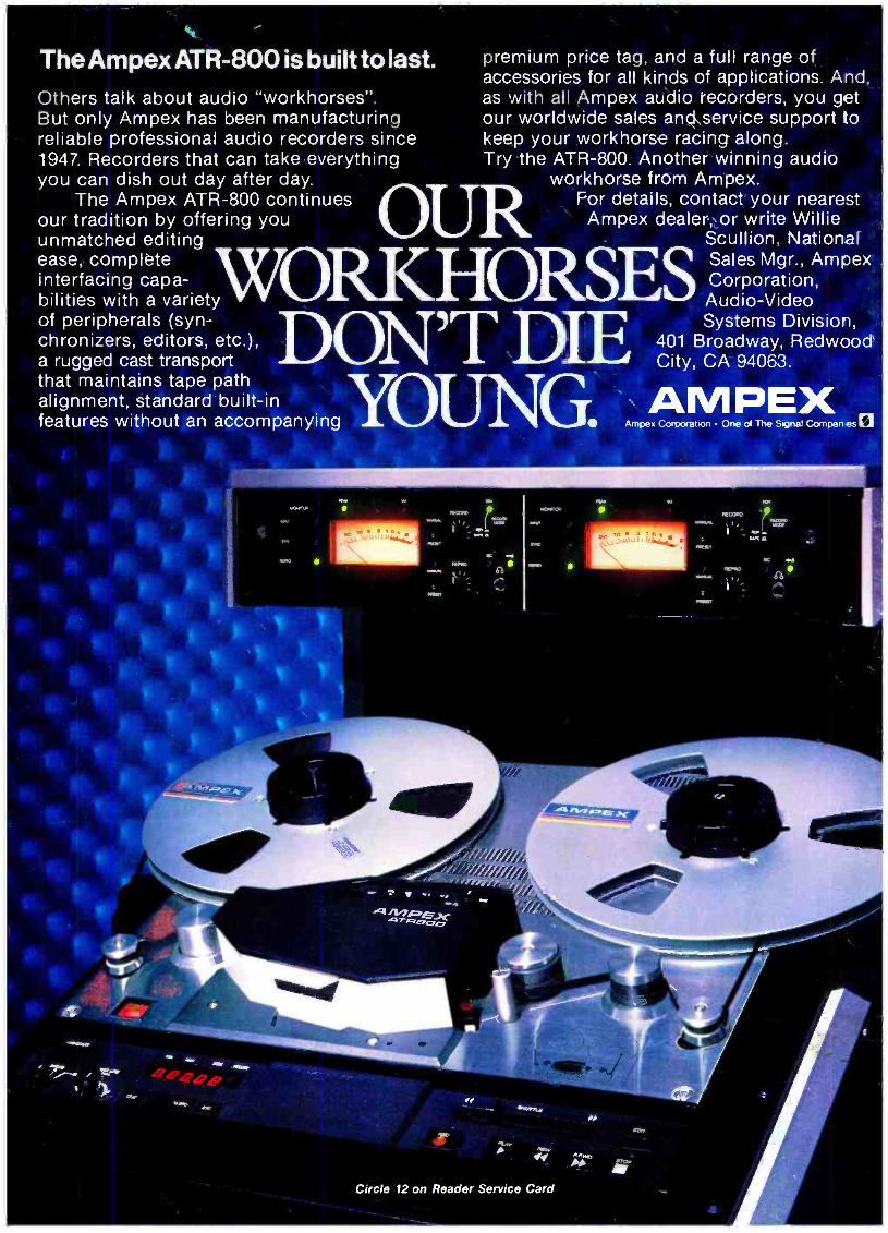
The Ampex ATR -800 is built to last.
Others talk about audio "workhorses ". But only Ampex has been manufacturing reliable professional audio recorders since 1947. Recorders that can take everything you can dish out day after day.
The Ampex ATR -800 continues our tradition by offering you unmatched editing ease complete interfacing capa-
chronizers, editorstors, etc.),
ORS bilities with a variety of peripherals
a rugged cast transport that maintains tape path alignment, standard built -in features without an accompanying
premium price tag, and a full range of accessories for all kinds of applications. And, as with all Ampex audio recorders, you get our worldwide sales and service support to keep your workhorse racing along. Try the ATR -800. Another winning audio
workhorse from Ampex. R For details, contact your nearest Ampex dealer, or write Willie
Scullion, National Sales Mgr., Ampex Corporation, Audio -Video ORSES
'T DIE Systems Division, 401 Broadway, Redwood City, CA 94063.
Circle 12 on Reader Service Card
I,