
Longitudinal Load, Distribution Factor of Helical 'Gears-
8
Longitudinal Load, Distribution Factor of Helical 'Gears - - - - T. Tobe, Professor K. Inoue, Associate Professor Facuhy of Engineering, Toheku University, Sendai, Japan This paper deals with the longitudinal load distribution and the bending moment distribution ofa pair of helical gears with a known total alignment error, The load distribution along the contact lines is calculated by the finite element method based on the plate theory including transverse shear deformation. Empirical formulas for both longitudinal load distrrbution factor and bending moment distribu- tion factor are proposed for practical use. The load distribution factor in AGMA 218.01 is examined, and it is concluded that the load distribution factor is dose to the calculated results if the value of unity is taken as the 'transverse load distribution factor. Introdudion The contact lines of a pair of helical gears move diagon- ally an the engaged tooth faces and their lengths consequently vary with the rotation of the gears. The load distribution along the contact lines is one of the most important factors for gear design, and some investigators have analyzed this problem. Hayashi'!' and Niemann and Schmidt(2) solved numeric- ally integral equations to obtain the load distribution, Niemann and Richter(ll proposed an experimental formula of the load distribution which was obtained by the photoelastic method. Conry and Seireg(41 developed a mathematical programming technique to estimate the load distribution and to obtain optimum profile modification. Kubo and Umezawa(SI obtained tooth bearings by means of the finite diHerenc.e method. The authors developed a finite element technique based on the plate theory including the transverse shear deformation to calculate the deflection of gear teeth, (6) then estimated the longitudinal load distribu- tion factor KH,B and determined the optimum amount of arc shaped crowning for both spur gears(1J and helical gears AUTHORS: DR. TOSHJMf TOBE is Professor Emeritus of Tohoku U'.riuersi· ty. He graduated from Tohoku Imperial University in 1944. and in 1957 he received the degree of Dr. Eng. Subsequently he studied the SlTength of gears under Professor G Niemann at the Technical Univer- sity at M"micil. From 196H985 he was a Professor at Tohoku Univer- sity. He is a member of 15M£, ISLE. a/'Id !SPI:. OR. KATSUMJ INOUE is atl Associate Professor of Tohoku Ulliversity in the Department of Precision Engitleeritlg. He earned his Imdergraduate and graduate degrees from Tohoku Utliversity, and JPI 1977 lie received the degree of Dr. Eng. Dr. Inoue is a member oflSME. 30 Gear Technology In a previous artide(8l, the longitudinal load distribution factor was defined as the ratio of the maximum load intensity to the average load on the contact lines at the worst posi- tion. Although the definition is logical, it is difficult to foresee the worst position. The average load is, therefore, generally unknown and the load distribution factor in the previous article is inconvenient Ior the practical use in gear design, In this article, this weak point is improved by introducing the average load an the contact lines of the minimum length. Formulas tor both load distribution factor and bending moment distribution factor are proposed, A comment is also given on 'the transverse load distribution factor in AGMA 2UI.01(9l. Assumptions for the Calculation of the Load Distri.butions The load distributions discussed in this article are for the involute helical gears which are generated by the basic rack (pressure angle = 20 deg, whole depth = 2.2Sm" and the radius of tip corner = O.375m,,) recommended in ISO 53-1974 as well as J[5 B 1701-1973 .. Although the 'tooth of helical gears is essentially twisted, the eHect of twist on the flexibility 'of tooth and the bending moment is assumed to be negligible. The thrust component of transmitted load is also. assumed to be neglected. Accord- ing to the assumptions, the cantilever plate with the flexural rigidity of the tooth is adopted as an adequate model. The plate is approximately represented by assembling 12 (in the direction of tooth height) x 21 max (in the direction of face
Transcript of Longitudinal Load, Distribution Factor of Helical 'Gears-

Longitudinal Load, Distribution Factorof Helical 'Gears- - - -
T. Tobe, ProfessorK. Inoue, Associate Professor
Facuhy of Engineering, Toheku University,Sendai, Japan
This paper deals with the longitudinal load distribution and thebending moment distribution ofa pair of helical gears with a knowntotal alignment error, The load distribution along the contact linesis calculated by the finite element method based on the plate theoryincluding transverse shear deformation. Empirical formulas for bothlongitudinal load distrrbution factor and bending moment distribu-tion factor are proposed for practical use. The load distribution factorin AGMA 218.01 is examined, and it is concluded that the loaddistribution factor is dose to the calculated results if the value ofunity is taken as the 'transverse load distribution factor.
IntrodudionThe contact lines of a pair of helical gears move diagon-
ally an the engaged tooth faces and their lengths consequentlyvary with the rotation of the gears. The load distributionalong the contact lines is one of the most important factorsfor gear design, and some investigators have analyzed thisproblem.
Hayashi'!' and Niemann and Schmidt(2) solved numeric-ally integral equations to obtain the load distribution,Niemann and Richter(ll proposed an experimental formulaof the load distribution which was obtained by thephotoelastic method. Conry and Seireg(41 developed amathematical programming technique to estimate the loaddistribution and to obtain optimum profile modification.Kubo and Umezawa(SI obtained tooth bearings by means ofthe finite diHerenc.e method. The authors developed a finiteelement technique based on the plate theory including thetransverse shear deformation to calculate the deflection ofgear teeth, (6) then estimated the longitudinal load distribu-tion factor KH,B and determined the optimum amount of arcshaped crowning for both spur gears(1J and helical gears
AUTHORS:
DR. TOSHJMf TOBE is Professor Emeritus of Tohoku U'.riuersi·ty. He graduated from Tohoku Imperial University in 1944. and in1957 he received the degree of Dr. Eng. Subsequently he studied theSlTength of gears under Professor G Niemann at the Technical Univer-sity at M"micil. From 196H985 he was a Professor at Tohoku Univer-sity. He is a member of 15M£, ISLE. a/'Id !SPI:.
OR. KATSUMJ INOUE is atl Associate Professor of TohokuUlliversity in the Department of Precision Engitleeritlg. He earned hisImdergraduate and graduate degrees from Tohoku Utliversity, andJPI 1977 lie received the degree of Dr. Eng. Dr. Inoue is a memberoflSME.
30 Gear Technology
In a previous artide(8l, the longitudinal load distributionfactor was defined as the ratio of the maximum load intensityto the average load on the contact lines at the worst posi-tion. Although the definition is logical, it is difficult to foreseethe worst position. The average load is, therefore, generallyunknown and the load distribution factor in the previousarticle is inconvenient Ior the practical use in gear design,In this article, this weak point is improved by introducingthe average load an the contact lines of the minimum length.Formulas tor both load distribution factor and bendingmoment distribution factor are proposed, A comment is alsogiven on 'the transverse load distribution factor in AGMA2UI.01(9l.
Assumptions for the Calculation of the Load Distri.butionsThe load distributions discussed in this article are for the
involute helical gears which are generated by the basic rack(pressure angle = 20 deg, whole depth = 2.2Sm" and theradius of tip corner = O.375m,,) recommended in ISO53-1974 as well as J[5 B 1701-1973 ..
Although the 'tooth of helical gears is essentially twisted,the eHect of twist on the flexibility 'of tooth and the bendingmoment is assumed to be negligible. The thrust componentof transmitted load is also. assumed to be neglected. Accord-ing to the assumptions, the cantilever plate with the flexuralrigidity of the tooth is adopted as an adequate model. Theplate is approximately represented by assembling 12 (in thedirection of tooth height) x 21 max (in the direction of face

width} rectangular elements whose thicknesses vary linearlyin the direction of tooth height. The deflection of the platewas calculated by FEM including both the transverse sheardeformation and the deformation at the elastic built-in edgeof the plate(6). Since the helical gear tooth does not have fullthickness near the end of tooth trace, the thickness at the cen-troid of element is adopted to estimate the flexibility at thepart of tooth. The characteristic of a helical gear tooth ismainly involved in the inclination of the contact lines. In themiddle plane of a tooth, the angle {3tm between the contactline and the tooth trace is presented by the followingexpression,
tan (3fm = sin [3b tan ~t cos ~J1
where at is the transverse pressure angle. The fundamentalequations'" 8) are summarized in Appendix 2.
Variations of the Load Intensity 3iI1.d the BendingMoment With. the Rotation of Gears
An example of the contact lines in the plane of action isillustrated in Fig. 1. The transverse base pitch Pbl is dividedinto six equal parts .. The lines with the same number are aset of contact line and the mesh advances in numerical order.The position of each line is indicated by the distance r alongthe side of the plane of action.
The load distributions of the pair of gears: mIT = 5, zl =Z2 = 20, [3 = 20 deg, b] = bz = 68.89 (fiJ = 1.5), werecalculated at every position of mesh shown in Fig. 1. The
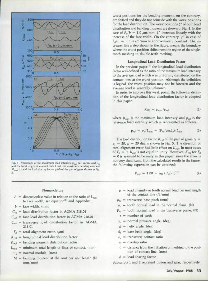
variations of the maximum load Pmax and the maximumbending moment mma~. of a tooth are shown in Fig. 2. Thetransmitted load is P,,/b = 600 N/mm. The direction oftotal alignment error Ffj and the rotation of gear 1 areillustrated in the figure. The abscissa indicates the positionof the contact line, that is, rI(E" + ffj) Pbt = o and 1meanthe initiation and the end of meshing, respectively. Since aset of contact lines whose interval is Pbl are in meshsimultaneously, the maximum load on the contact lines andthe maximum bending moment of gear 1 vary as shown inFig. 3. The total length of contact lines L, the mean load Pmand the load sharing factor ..p are also shown in the Hgure.In the case of F{J = 0, Pm"" and MmiIX reach maximum at theposition where L is minimum. When the gears have totalalignment error, the worst meshing positions for the loaddistribution are fairly close to 'the position of L = Lmin. The
.-. - -Ir·· .i" " ' . ~~,. ~-;,:- ~~~-'~~~~ ".~. ~-:::
Fig. 1- Contact lines on the plane of action (m" ~ 5. b ~ 68.89, Pbl ~15.59, fa ~ 1.44)
Fig. 2 - Variations of the maximum load on a tooth (al and the maximumbending moment (bl (m"l = 5. zl = zl = 20, (3 = 20 deg, f{1 ~ 1.5,PII,Ibm" = N/mmz)
JulyIAugust 1985 31
ee.....z
worst positions for the bending moment, on the contrary,are shifted and they do not coincide with the worst positionsfor the load distribution. The worst positions r of both loaddistribution and bending moment are shown in F~g.4. In thecase of Fplb = 1.0 p:m/mm, t* increases linearly with theincrease of the face width. On the contrary, t* in case offa1b = -1.0 J.!,mfmm is approximately constant. The in-crease, like a step shown in th figure, means the boundarywhere the worst position shifts from the region of the single-tooth meshing to double-teeth meshing.
Longitudinal Load Distribution FactorIn the previous paper,181 the longitudinal load distribution
factor was defined as the ratio of the maximum load intensityto the average load which was u~iformly distributed on thecontact lines at the worst position. Although the definitionis logical, the worst position may not be Foreseen and theaverage load is generally unknown.
In order to improve this weak point, the following defini-tion of the longitudinal load distribution factor is adoptedin this paper:
(2)
I(
aE
Q.
(Q) ~e/b= 0 ~m/mm
where Pma~ is the maximum load intensity and Ptel is thereference load intensity which is represented as follows:
Pref = p"ILmin = (P",!cos{3/J/Lmin (3)
The load distribution factor KHi3 of the pair of gears ZJ =%2 = 20, t3 = 20 deg is shown in Fig. 5. The direction oftotal alignment error had little effect on KHd• In most casesof F{j = 0, KH{J is not equal to unity. However, KHfJ for Fjj
= o is assumed to be unity ill this paper, since the 'error isnot very significant, From the calculated results in the figure,the following expression can be obtained:
2000 0 5 1.0
e 600~~ :Toe:e:~~~:~~~3000 0 5 1.090
6000~--------~--------~E (c)E
z
04
0.5 1.0r / (£~·£eI) Pbt
Fig.. 3-Variatiom, of the maximum load intensity Pmax (aJ. mean load Pmand the total length of contact lines L (b), the maximum bending momentM""", (el and the load sharing factor '" (d) of the pair of gears shown in Fig.2. (4)
Nomenclafure
A dimensionless value in relation to the ratio of Lmin
to face width, see ,equation(S) and Appendix 1
face width, (mm)bem load distribution factor in AGMA 218.01
Cmf = face load distribution factor in AGMA 218.01
Cmf transverse load distribution factor in AGMA218.,01
FfjKI#3
KmaLmin
total alignment error, (/Lm)
longitudinal load distribution factorbending moment distribution factor
minimum total length of lines of contact, (mm)
normal module, (mm)
bending moment at the root per unit length (Nmm/mm)
mil
M
p load intensity or tooth normal load per unit lengthof the contact line (N /mm)
Pbl = transverse base pitch (mrn)
Pn = tooth normal load in the normal plane, (N)
P"I = tooth normal load in the transverse plane, (N)
z = number of teeth
a" normal pressure angle, (deg)(3 helix angle, (deg)
base helix angle, (deg)
transverse contact ratioffJ overlap ratio
r distance from the initiation of meshing to the posi-tion of contact line, (mm)
1/1 = load sharing factor
Subscripts 1 and 2 represent pinion and gear, respectively,
Ju IYiAugust 198533

Fig. 4-Worst position r* of helical g iUS in relation to load intensity {aland bending moment (b)
where ClH is estimated from the value of KHIJ for IFlil/b1.0 p.m/mm. Introducing the dimensionless value
(5)
equation (2) is transformed as follows:
(6)
KHII* for IFpl/b = 1.0 p.m/mm is shown in Fig. 6. The rela-tion between CXH - {KH/I IFill/I> ~ 1.o..JP"tlbm" andfll isshown in Fig, 7 and the following expression can be derivedfOfffJ ~1.0:
Promequations (4) to (7), the approximate expression of KHIJfor the pair of gears of {3 = 20 deg is obtained. In the sameway, similar expressions for gears of {3 = 10 deg and 30 degare obtained. These are arranged and the empirical formulais finally determine-d as follows:
(.cP/EJ+8.77 )
K.1fJ = 1.00+ I A -1.00 (IF~ l/blLl
.,jPn,lbm. (8)
34 Gear Technol'ogv
- -- "aO•51.01.52.02.!I
Fig. 5-Longitudinal load distribution factor KHd
Fig. 6 - Modified load distribution factor KH/ of gears Z I = Zz = 20 wi th
the effective alignment error IFailb - 1.0 j).m/mm
Fig. 7 - Value of a H (aH = {KHI/1IFt! 1& _ 1.0 ..jp mIbm"J
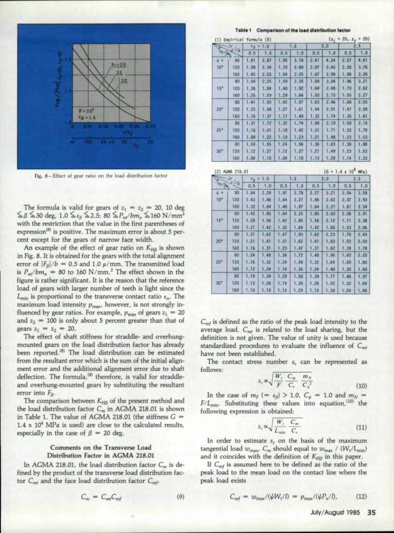
fig. 8 - Effect of gear ratio on the load distribution factor
The formula is valid for gears of %1 = %2 = 20, 10 deg~13 ~30 deg, 1.0 ~f.ll ~2.5; 80 ~P ..t/bm" ~160 N/mm2with the restriction that the value in the first parentheses ofexpression(8l is positive. The maximum error is about 5 per-cent ,except for the geiLrs 'of narrow face width.
An 'example of the effect of gear ratio on I<H6 is shownin Fig,S. It is obtained for the gears with the 'total alignmenterror ,of IF.IIl!b - 0.5 and 1..0' IL/mm. The transmitted loadis P,,!bm" = 80 to 160 N I mm.:z The effect shown in thefigure is rather significant. It is the reason that the referenceload of gears wi,th huger number of teeth is Ijght since theLmm is proportional to the transverse contact ratio Ea' Themaxim~m load intensity 1"rrw<' however. is not strongly in-fluenced by gear ratios. For example, "mal! of gears z] = 20and Z2 = 100 is only about 5 percent greater than, that ofgears %1 = %1 = 20.
The effect ,of shaft stiffness for straddle- and overhung-mourned gears on the load distribution factor has alreadybeen reported.(S) The load distribution can be estimatedfrom the resultant error which is the sum ·of 'the initial align-ment error and ,the additional alignment 'error due to shaftdellection, The formula, (81therefore. is valid for straddle-and o,verhu:ng-mountedgears by substituting the resultanterror into Ffj.
The comparison between KH6 of the present method andIthe load distribution factor em in AGMA 218.01 is shownin Table 1. The value of AGMA 218.01 (t'he stiffness G =1.4 x 10" M-Pa is used) are dose to the caiculated results.especiaUy in the case of (3= 20 deg,
'Comments ,on the Transverse loadDistribution Fade))' in AGMA 21S.m
In AGMA 218.01. the load distribution factor Crn is de-fined by the product of the transverse load distribution fac-'tor Crn! and the face load distribution facto·r Crnf.
(9)
II ,Ellplrlcll f01"llUla (8) IZI • lO. Z'2' • ,lO)
~~/ .. ~~·~a~·~I~.D~~ __ ~1.~5__ 4-~~2~.~0~+-~;2~.5~~I ~t<~..:~b~~0~.S~~1~.O~_O~.~5+-~I~.O~~O~.S~~I'~01-~O~.5~171~.~O~"'.8 • 80 1.81 Z.87 1.95 3.18 2.41 4.24 2.57 4.61
1.70 2.,60 2.07 3.45 ,2.20' 3.76,10· 120 1.58 2.34
1. 36 1.83 l.3'8 1. 881.21 1.49 1.23, 1.S31.13 1.29 1.14 1.33
160 1.45 2.03 1.54 2.25 1.87 2.99 1.911 3.2680 1.54 2.25 1.59 2.35 1.89 33M 1.96 3.21
IS· 120 1.36 1.84 1.40 1.92 1.64 2.48 1.70 2.62160 1.26 1.59 1.29 1.'66 1.50 2.1S 1.55 2.2180 1.41 1.93
120 1.25 1.58160 1.16 1.31
1.42 1.971.27 1.611.17 1.40
1.63 2.46 1.68 2.;551.44 2.01 1.47' 2.091.32 1.74 I.lS LSI
20·
80 1.31 1.72120 1.18 loCI160 1.09 1.22
1.32 1.74
1.18 1.42LID 1.23
1.48 2.10 1.50 2.161.31 1.71 i.n 1.161.21 1.48 1.23, 1..53
25"
80 1.24 1.55120 1.12 1.27160 1.04 1.10
1.24 1.561.12 1.271.04 1.10
30·
(2) AliMA 218 01
~FI '8 0 1.0 1.5 2.0 2.5~,,"~0.5 1.0 0.5 1.0 ' D.5 1.0 0.5 1.0S • 80 1.64 2.29 1. 91 2.78 2.21 3.21 2.54 3.5910" 120 1.43 1.86 1.64 2.27 1.86 2.62 2.D7 2.93
160 1.32 1.64 US 1.91 1.64 2.27 1.81 2.5480 1.42 I.BS 1.64 2.25 1.85 UiO 2.06 2.91
ISO. 120 1.28 1.56 1.42 1.85 1. S6 2.12 1. 71 2.38160 1.21 1.42 lo3Z 1.64 1.42 1.85 1.53 2.0680 1.31 1.62 1.47 1.93 1.62 2.23 1. 78 2.49
20· 120 1.21 1.41 1.31 1.62 1.41 1.83 1.52 2.03160 1.16 1.11 1.23 1.47 1.31 1.62 1. 39 1.18
I80 1. 24 1.48 1.36 1.12 1.48 1.9ii 1.60 2.20
25" 120 1. 16 1.32 1.24 1.48 1.32 1.64 1.40 1.80
160 1. 12 1.24 LIB 1.36 1.24 l.48 1.30 1.6080 1.19 1.39 1.29 1.58 1.3!1 1.17 1.46 1.97
3~" 120 1.13 , .26, 1.19 1.3,9 1.26 1.52 1.32 1.64160 1.10 1.19 1.15 1.29 1.19 1.39' 1.2' 1.48
emf is defined as the ratio of the peak load intensity to Itheaverage load. Cml is related to the load sharing. but 'thedefini.tion is not given. The value of unity is used becausestandardized procedures. to evaluate the influence of em'have not been established,
The contact stress number Sc can be represented asfollows:
In the case of mF ( ffj) > 1.0. C~ - 1.0 and mN -FILaun. Suhsmutir\gthese values into equation. [101 thefollowing expression is obtained:
unInorder to estimate Sc on the basis of 'the maximum
tangential load wTJW(' em should equal to WII'WI: I (Wr/Lmin)and it coincides with the definition of .1(Hfj in this paper.
If c'mf is assumed here to be defined as the ratio of thepeak load to Ithe mean load on the contact line where thepeak load exists
emf"" wmax/(~Wtm -' pmax/(~P,,/1),
July/August 1985 35
(U)
Eu
o 0'.5 1.0 1.'5 2.0 2.5Ell
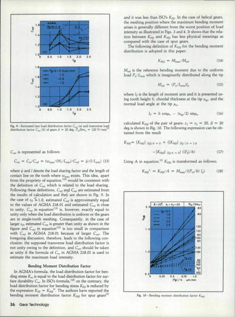
Fig. 9 - Estimated face load distribution factor em! (cd and tra nsverse loaddistribution factor eml (b) of gears fj ... 20 deg, P",lbmn ... 120 Imm'21
eml is represented as follows:
where 1{1 and I denote the load sharing factor and the length of'contact line on the tooth where wmaxexists. This idea, apartfrom the propriety of equation, (12) would be consistent withthe definition of e,m which is related to the load. sharing.Following these definitions, C~'fan..d Cmt are estimated fromthe results of calculation and they are shown in Fig. 9. Inthe case of s« ~ 1.0, estimated Cmf is approximately equalto, the values of AGMA 218.01 and estimated Cmt is doseto unity. em! in equation(]3) is, however, exactly equal tounity only when the load distribution is uniform or the gearsare in single-tooth meshing. Consequently, in the 'case oflarger ED' estimated em' is greater than unity as shown in thefigure and. emf in equation(U} is too small in comparisonwith Cmf in AGMA 218.01 because of larger emt. Theforegoing discussion, therefore. leads to the following con-elusion: the supposed transverse load distribution factor isnot unity owing to the definition, and em,. should be takenas unity if the formula of em in AGMA .218.01 is used toestimate the maximum load intensity ..
8endmg Moment Distribution F.adorIn AGMA's formula, the load distribution factor for ben-
ding stress Km is equal! to the load distribution factorfor sur-face durability Cm- In ISOs formula, no)on the contrary,theload distribution factor for bending stress KFfj is reduced bytheexpression KFfj = KHt. The authors have reported thebending moment distribution Factor KMfJ for spur gears(7}
36, Gear fechnology
and it was less than ISO's KF/3' ln the case of helical gears,the meshing position where the maximum bending momentarises is generally different hom the worst position of loadintensity as illustrated in Figs. 3 and 4. It shows that the rela-tion between KHd and KM/3 has less physical meanings ascompared with the case of spur gears.
The following definition of KMfJ for the bending momentdistribution is adopted in this paper:
(14)
Mref is the reference bending moment due to the uniformload P,/Lmin which is imaginarily distributed along the tip
(15)
where Jp is the length of moment ann and it is presented us-ing tooth height 11, chordal thickness a.t the tip Stip' and thenormal load angle at the tip lin'
(16)
calculated KMfJ of the pair of gears:zl = Z2 = 20, ~ = 20'deg is shown in JOig.10. The following expression can be ob-tained from the result
(17)
Using A in equation, (51 KMfj is transformed as follows:
(18)
Fig, 10 - Bending moment distribution factor KMIJ

1.
40 120 160
Fig. U -Modified bending moment distribution factor KMllof gears ZI =Zl ~. 20 with the effective alignment error IF"lib = 1.0 /Lffi/mm
KMtl" for IFI3I/,b= 0 ,~mjmm in approximately equal to O.Sand the value for If~l/,b = l..o ILm/mm is illustrated in Hg.,11. The relation between a M = [KMtl*IIF,Bl/b _ 1.ovP',.y'bml1,ande(j is shown in Fig. 12 and the following expression canbe derived for f:{l ~ 1.0:
(19)
Fl!'Omequations(l7) to, (19) the approximate formula of KMtlfor the pair of gears of fJ = 20. deg is obtained. In 'the sameway, similar formulas for the gears of {3= 10 deg and 30deg are obtained and the following formula is finallydetermined.
J( r - (¢...,crJ+5.05 -O.5_')·.'(IF~l/b_)J. '(2~.)-MJ=AtO•5+ rr. - u
'JP",lb.m"
The formula is valid for the gears or Zl= Zz = 2.0, 1.0 deg~{3"-30 deg, 1.0 ~E/1 ~2.S; 8O~P~t I bm; ~160 N/mm2with the restriction of (cPMEI3 + 5.05) I .,JPl1!.bmn - .0 ..5 >O. The maximum error is about 6 percent 'except for a partof light load where the err ill' exceeds 10 percent Since thebending moment distribution factor is less than the loaddistribution factor, the effect of gear ratio shown in Fig .. 8can also be adopted in this case as the value ofthe safe side.
It should be noted that the factor KMIJ is obtained at theworst posifion of gears with the alignment error. As the posi-tion does not gene~ally coincide with the worst position inthe case of FIJ = A., the helical. factor Ch in AGMA strengthrating formula is still valid for the gears without the align-ment error. The helical factor calculated by the presentmethod has already been shown in the previous paper!8)
ConclusionsThe longitudinal load distribution on the contact. lines and
the bending moment distribution along the root of helicalgears are calculated by FEM which is based on the plate
1 '5
0.'5 1.0 1.5 2.'0[II
Fig. 12 - Value of a ,..M (a M = IKMD llf,Bllb - LO ";P;"I/)m,,)
theory including the transverse shear deformation.The longitudinal load distribution factor KHI3 caused by
the effective alignment error is obtained and an empirical for-mula of KH(j is proposed. The load distribution factor ern inAGMA 218.01 is dose to the values calculated by the presentmethod ..A formula is also proposed for the estimation of themaximum bending moment of gears with the alignment error.
A supposed definition of the transverse load distributionfactor is examined and it leads to theconclusion tha.t thetransverse load distribution factor in AGMA 218.01 shouldbe taken as unity if the formula of load distribution factorC~ is used to estimate the maximum load intensity.
Relerences
1.. HAYASHI, K., Trans. J5ME, Vol. 28, 1962. pp. 1,093-1101.
2. NIEMANN, G .• and SCHMIDT, G .• VDl-Z, Vol. 113, 1971,pp .. 165-170.
3. NfEMANN, G., Maschinenelemente .ll, Springer, 1965.4. CONRY. T. fl.• and SEIREG, A., Trans, ASME, Vol. 9.5, 1973.,
pp, 1115-1122.
5. KUBO, A., and UMEZAWA, K., Trans. J5M£. Vol. 43, 1977,Pl'. 2771-2783.
6. TOBE. T.• KATO, M., and INOUE, K., ASME Journal ofMechalll'cal Design, Vol. 100, 1978, pp, 374-381.
7. TOBE, T., and INOUE, K., ASM..Epaper 8O-C2/DET -45, 1980.
8. INOUE, K.. and TOBE. T., Proc. Int. Symp. on Gearing &Power Transmissions, Tokyo, Vol. 2, 1981, Pl'. 165-170.
9 .. AGMA 218.01, Dec. 1982.10. IS0lOIS 633611, 1983.11. "Calculation of the Load Capacity of Involute Cylindrical!
Gears," Report No. 137, f. TSME, Vol. 72, 1969, pp. 14.&-159.
Appendix.lThe rmrumum of total length of contact lines Lmin is
calculated by the foUowing equation:(ll)
(0) if frC(t,J + frc(fJ) < I,f re(f,,)f reef oJ ),
Nh=I------f"fJ
N"-I-frc(f,,)/f,, (~~<I)
(b) if frc(f .. ) + fre(f~) ? I.
N. _U_-_fr_cC....;Eu;;...>..;,I_I_I-_fr_C(....;EJ;;...I_'j/1=1-'fufp
July/August 1985 37

fig. A.l- Value of Nb
where frc (X) denotes the fraction of X. The function Nb isshown in Fig. A 1, The dimensionless value A in equation(5)can be calculated by using Nb
(A.3)
In the case that the face contact ratio mF ( = E,gJ in AGMA218.01 is greater than unity, the load sharing ratio mN isdefined by mN = F / Lmin• Therefore, A is expressed asfollows:
COS{3hA=--
m,(AA)
Appendix .2The matrix [Hk] for gear k(k = 1, 2) is defined by wk.li'
which is the deflection at node f on the contact line due toa unH normal load applied to node i.
(AS)
)T = transposed matrix
The deflection wlt.ii is calculated by FEM. When a pair ofteeth are in mesh, the distributed load {P} along the contactline is related to the sum of the deflection of the teeth and
38 Gear Technology
the relative approach due to elastic contact.
[H] {P} = {w} (A6)
The elements of matrices [HJ and {w} are
(A.7)lVt = "'1.J + \1.'~.1 + •.Ij'I~.1
where Wp, is the relative approach at node i and Gil isKronecke;'s delta. When some pairs of teeth I, U, ... arein mesh matrices [HIL [HilL .. ' . are separately obtained. Ifthe load on a pair of teeth is assumed to have littleeffect onthe deflection of other pair of teeth, the matrix IHI inequa-tion (A.6) is diagonally constructed as follows:
__ [IHd 0 ][H] = 0 (HII J (A.S)
.The equation (A.6) is solved under the followingconditions:
r;,P,=P"s,
w,+ WOO =(r/oIOI +r/j202)Cos{3I,
P, =0
(A.9)(node in conracr)
(node not in contact)
where s. [ttmlis the spacing at node j caused by the effec-rive alignment error, rb is the radius of base cylinder and e(rad) is the rotating angle of gear.
This article was contributed by the Power Transmission and Gearing Com-mittee for presentation at the Design Engineering Technical Conference. Or-tober, 1984 of TIle American Society of Mechcmical Engineers. Paper No.84-DET-68.
E-4 ON READ.ERREPlV CARD
MATERIAL SHECTION. __(continued from page 46)
and accuracy, and improved lubrication- rather than changesin material- are required to solve this problem.
ScoringIn some heavily loaded or high-speed gearing, scoring may
occur under boundary HIm conditions. This is believed tobe caused by frictional heat which reduces the lubricant pro-tection sufficiently to allow welding and tearing of the profile.
Materials selection alone will not prevent scoring; properlubricants and design geometry are required. This difficultyis seldom encountered in the conventional industrial geardrive. AGMA 217.0'1, Oct. 1967, "AGMA InjormationSheet - Gear Scoring Design Guide for Aerospace Spur andHelical Power Gears" provides helpful recommendations foravoiding scoring.(This article will be continued in the September/October 1985 issue of GEARTECHNOLOGY. J
Reprinted from Modem Methods of Gear Man"fachm? 4th Edition, PublishedNationo! Broaclland Mac/rine Division of LEar Siegler. lnc., 17500 TwentyThree Mile Rd .• MI. Clemens. MI 48044
E-5 ON READER REPlY CARD