Long Span Roofs - LVL Portal Frames and Trusses Documents/Design... · 2.3 Portal Frame...
39
32 Technical Design Guide issued by Forest and Wood Products Australia Long Span Roofs - LVL Portal Frames and Trusses
Transcript of Long Span Roofs - LVL Portal Frames and Trusses Documents/Design... · 2.3 Portal Frame...
32
Technical Design Guide issued by Forest and Wood Products Australia
Long Span Roofs - LVL Portal Frames and Trusses

WoodSolutions Technical Design Guides
A growing suite of information, technical and training resources, the Design Guides have been created to support the use of wood in the design and construction of the built environment.
Each title has been written by experts in the field and is the accumulated result of years of experience in working with wood and wood products.
Some of the popular topics covered by the Technical Design Guides include:
• Timber-framed construction• Building with timber in bushfire-prone areas• Designing for durability• Timber finishes• Stairs, balustrades and handrails• Timber flooring and decking• Timber windows and doors• Fire compliance• Acoustics• Thermal performance
More WoodSolutions Resources
The WoodSolutions website provides a comprehensive range of resources for architects, building designers, engineers and other design and construction professionals.
To discover more, please visit www.woodsolutions.com.au The website for wood.
01
Technical Design Guide issued by Forest and Wood Products Australia
Timber-framed Constructionfor Townhouse Buildings Class 1aDesign and construction guide for BCA compliant sound and fire-rated construction
04
Technical Design Guide issued by Forest and Wood Products Australia
Building with Timber in Bushfire-prone AreasBCA Compliant Design and Construction Guide
09
Technical Design Guide issued by Forest and Wood Products Australia
Timber FlooringDesign guide for installation
Cover image: Netball Central, Sydney Olympic Park, Architect: Scott Carver Photographer: Geoff Ambler
WoodSolutions is an industry initiative designed to provide independent, non-proprietary information about timber and wood products to professionals and companies involved in building design and construction.
WoodSolutions is resourced by Forest and Wood Products Australia (FWPA – www.fwpa.com.au). It is a collaborative effort between FWPA members and levy payers, supported by industry bodies and technical associations.
This work is supported by funding provided to FWPA by the Commonwealth Government.
ISBN 978-1-925213-30-0
Acknowledgments
Authors: Pierre Quenneville, Felix Scheibmair
The research and development forming the foundation of this Design Guide as well as its preparation and production was proudly made possible by the shareholders and financial partners of the Structural Timber Innovation Company Ltd.
First published: 2013 Revised: April 2016
© 2016 Forest and Wood Products Australia Limited. All rights reserved.
These materials are published under the brand WoodSolutions by FWPA. This guide has been reviewed and updated for use in Australia by TDA NSW.
IMPORTANT NOTICE
While all care has been taken to ensure the accuracy of the information contained in this publication, Forest and Wood Products Australia Limited (FWPA) and WoodSolutions Australia and all persons associated with them as well as any other contributors make no representations or give any warranty regarding the use, suitability, validity, accuracy, completeness, currency or reliability of the information, including any opinion or advice, contained in this publication. To the maximum extent permitted by law, FWPA disclaims all warranties of any kind, whether express or implied, including but not limited to any warranty that the information is up-to-date, complete, true, legally compliant, accurate, non-misleading or suitable.
To the maximum extent permitted by law, FWPA excludes all liability in contract, tort (including negligence), or otherwise for any injury, loss or damage whatsoever (whether direct, indirect, special or consequential) arising out of or in connection with use or reliance on this publication (and any information, opinions or advice therein) and whether caused by any errors, defects, omissions or misrepresentations in this publication. Individual requirements may vary from those discussed in this publication and you are advised to check with State authorities to ensure building compliance as well as make your own professional assessment of the relevant applicable laws and Standards.
The work is copyright and protected under the terms of the Copyright Act 1968 (Cwth). All material may be reproduced in whole or in part, provided that it is not sold or used for commercial benefit and its source (Forest and Wood Products Australia Limited) is acknowledged and the above disclaimer is included. Reproduction or copying for other purposes, which is strictly reserved only for the owner or licensee of copyright under the Copyright Act, is prohibited without the prior written consent of FWPA.
WoodSolutions Australia is a registered business division of Forest and Wood Products Australia Limited.
Owing to copyright boundaries, this Guide must only be used in Australian States and Territories. Downloading or distributing this Guide or any of the materials therein in any other area is prohibited.

Page 3#32 • Long Span Roofs - LVL Portal Frames and Trusses
Contents
1 Introduction 5
2 Scope 6
2.1 Summary of Design Parameters ................................................................................................. 6
2.1.1 Portal Frames ............................................................................................................................... 6
2.1.2 Truss Design Parameters ............................................................................................................. 8
2.2 Design Solution Criteria ............................................................................................................... 9
2.3 Portal Frame Arrangements ......................................................................................................... 9
2.3.1 Portal Frame with Internal Prop ................................................................................................... 9
2.3.2 Double-Pitch (Gable) Portal Frame ............................................................................................. 9
2.4 Truss Arrangement .................................................................................................................... 10
2.5 Frame/Truss Spacing ................................................................................................................. 10
2.6 Roof Inclination .......................................................................................................................... 10
2.7 Importance Level ....................................................................................................................... 10
2.8 Design Location ......................................................................................................................... 10
2.9 Design Life ................................................................................................................................. 10
2.10 Pre-Cambering .......................................................................................................................... 10
2.11 Connections ............................................................................................................................... 10
2.12 Loadings .................................................................................................................................... 11
2.12.1 Permanent Loads (G) ................................................................................................................ 11
2.12.2 Imposed Loads (Q) ................................................................................................................... 11
2.12.3 Wind Loads (W) ......................................................................................................................... 11
2.12.4 Load Combinations ................................................................................................................... 12
3 Portal Frame with Inner Prop Solutions 13
3.1 Gravity and Wind Terrain – Category 2 ...................................................................................... 13
3.2 Gravity and Wind Terrain – Category 3 ...................................................................................... 14
4 Double-Pitch Portal Frame Solutions 16
4.1 Gravity and Wind Terrain – Category 2 ...................................................................................... 16
4.2 Gravity and Wind Terrain – Category 3 ...................................................................................... 17
5 Truss Solutions 18
5.1 Gravity and Wind Terrain – Category 2 ...................................................................................... 18
5.2 Gravity and Wind Terrain – Category 3 ...................................................................................... 19
6 Summary of Trends and Findings 21
6.1 Portal Frames ............................................................................................................................. 21
6.1.1 Double-Pitch Portal Frame ........................................................................................................ 21
6.1.2 Internal Propped Portal Frame and Comparison ...................................................................... 22
6.2 Trusses ....................................................................................................................................... 23
6.2.1 Thicknesses ............................................................................................................................... 23
6.2.2 Effect of T Stiffener on Compression and Tension Capacities .................................................. 23
6.2.3 Top Chord .................................................................................................................................. 23
6.2.4 Bottom Chord ............................................................................................................................ 23

Page 4#32 • Long Span Roofs - LVL Portal Frames and Trusses
Contents
7 Example A: Wind Load Calculation 24
8 Supporting Materials – Portal Frames 25
8.1 Internal Propped Portal Frame Wind Pressures and Ratios ..................................................... 25
8.2 Double-Pitch Portal Frame Wind Pressures and Ratios ........................................................... 27
8.3 Flange Width Selection to Minimise Wastage .......................................................................... 28
9 Example B: Truss Design Example 29
9.1 Deflection Check ....................................................................................................................... 29
9.2 Member Design ........................................................................................................................ 30
9.2.1 Column ..................................................................................................................................... 30
9.2.2 Top Chord ................................................................................................................................. 30
9.2.3 Bottom Chord ........................................................................................................................... 30
9.2.4 Diagonal Lacings ...................................................................................................................... 32
9.2.5 Vertical Lacings ......................................................................................................................... 33
References 36
Appendix A – Notation 37
Page 5#32 • Long Span Roofs - LVL Portal Frames and Trusses
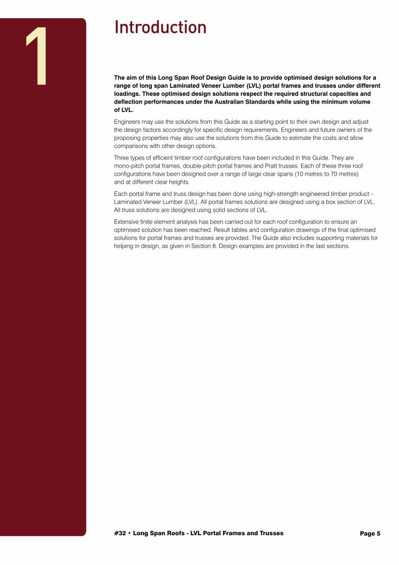
The aim of this Long Span Roof Design Guide is to provide optimised design solutions for a range of long span Laminated Veneer Lumber (LVL) portal frames and trusses under different loadings. These optimised design solutions respect the required structural capacities and deflection performances under the Australian Standards while using the minimum volume of LVL.
Engineers may use the solutions from this Guide as a starting point to their own design and adjust the design factors accordingly for specific design requirements. Engineers and future owners of the proposing properties may also use the solutions from this Guide to estimate the costs and allow comparisons with other design options.
Three types of efficient timber roof configurations have been included in this Guide. They are mono-pitch portal frames, double-pitch portal frames and Pratt trusses. Each of these three roof configurations have been designed over a range of large clear spans (10 metres to 70 metres) and at different clear heights.
Each portal frame and truss design has been done using high-strength engineered timber product – Laminated Veneer Lumber (LVL). All portal frames solutions are designed using a box section of LVL. All truss solutions are designed using solid sections of LVL.
Extensive finite element analysis has been carried out for each roof configuration to ensure an optimised solution has been reached. Result tables and configuration drawings of the final optimised solutions for portal frames and trusses are provided. The Guide also includes supporting materials for helping in design, as given in Section 8. Design examples are provided in the last sections.
Introduction
1
Page 6#32 • Long Span Roofs - LVL Portal Frames and Trusses
2Scope
2.1 Summary of Design Parameters
This section contains a summary of the design parameters and assumptions for each type of long span roof design. The detailed explanations are provided in later sections.
2.1.1 Portal Frames
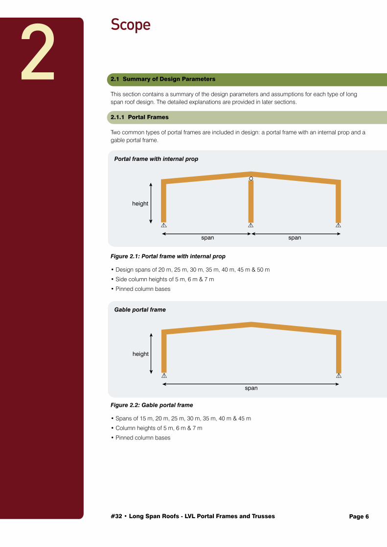
Two common types of portal frames are included in design: a portal frame with an internal prop and a gable portal frame.
Figure 2.1: Portal frame with internal prop
• Design spans of 20 m, 25 m, 30 m, 35 m, 40 m, 45 m & 50 m
• Side column heights of 5 m, 6 m & 7 m
• Pinned column bases
Figure 2.2: Gable portal frame
• Spans of 15 m, 20 m, 25 m, 30 m, 35 m, 40 m & 45 m
• Column heights of 5 m, 6 m & 7 m
• Pinned column bases
span
height
span
height
span
Portal frame with internal prop
Gable portal frame

#32 • Long Span Roofs - LVL Portal Frames and Trusses Page 7
Figure 2.3: Typical box beam.
Cross section and material
All portal frame solutions are designed as box sections of Grade 11 LVL.
• The depth (d) of the box sections ranges from 400 mm to 1200 mm.
• The width (bf) is selected to maximise material utilisation from a 1200 mm-wide LVL billet. Refer to Section 8.3.
• Two optimised solutions are provided for every portal frame, one in 45 mm web thicknesses (tw), the other in 63 mm web thicknesses (tw).
All webs of the box sections are with two cross-bands.
Figure 2.4: Gable portal frame.
Other assumptions
• 8 m frame spacing
• 5° degrees roof pitch
• Importance Level 2
• Design location: Auckland
• Design life: 50 years
• Pre-cambering equal to self-weight deflection
• Fixed rafter to column and apex connections
• Same cross-section throughout the whole portal frame

#32 • Long Span Roofs - LVL Portal Frames and Trusses Page 8
Figure 2.5: Trussed roof.
2.1.2 Truss Design Parameters
• Design spans of 50 m, 60 m, 70 m
• Column clear heights of 7 m
• Pinned column bases
Cross section and material
All truss members are designed as solid sections of Grade 11 LVL.
• The depth (d) of the truss members ranges from 150 mm to 400 mm.
• The width (b) of the truss members are either 126 mm or 180 mm.
Figure 2.6: Trussed roof.
Other assumptions
• Pratt truss configuration
• 8 m truss spacing
• 5° degrees roof pitch
• Importance Level 2
• Design location: Auckland
• Design life: 50 years
• Pre-cambering equal to self-weight deflection
• Simple pinned connections throughout the truss
• All connection requirements to be met using timber rivets

#32 • Long Span Roofs - LVL Portal Frames and Trusses Page 9
2.2 Design Solution Criteria
The following sections are provided to clarify the design criteria, design conditions, loadings and assumptions made in each design.
All design solutions must satisfy two important criteria:
1. Optimal solution: All final solutions must achieve the required structural capacities and deflection performances under the Australian Standards while using the minimum volume of timber (see Section 8.4).
2. Minimised wastage: In order to minimise the wastage of LVL within each portal frame and truss project, the flange width of a box section will always be a width that maximises material utilisation from a 1200 mm-wide LVL billet (see Sections 8.3 and 8.4).
Both criteria have a common objective of saving costs. By adopting optimised design solutions that use the minimum volume of timber and have minimised wastage in mind, the material cost for a project will be reduced to a minimum and the LVL supplied for the project will be efficiently used.
2.3 Portal Frame Arrangements
2.3.1 Portal Frame with Internal Prop
Figure 2.7: Portal frame with internal prop.
This arrangement is constructed by a double-pitch frame with an inner prop column that is pinned to the apex of the double-pitch frame.
The end columns to rafters (knee joints) and the apex joint between the rafters are fixed joints. The inner prop column carries axial loads only, and does not contribute to moment resisting.
2.3.2 Double-Pitch (Gable) Portal Frame
Figure 2.8: Double-pitch (gable) portal frame.
The double-pitch portal frame is the most standard configuration of a portal frame structure. The double-pitch portal frames are assumed to be a ‘two-pin’ configuration. The column to rafter joints (knee joints) and the apex joint between the rafters are fixed joints. The bases of the columns are pinned. The same cross-section is used to construct the entire portal frame.
span
height
span
height
span

#32 • Long Span Roofs - LVL Portal Frames and Trusses Page 10
2.4 Truss Arrangement
The Pratt truss configuration is adopted for all timber trusses. The truss members are assumed to be joined using simple connections throughout.
Steel columns are used to support the trusses. LVL columns are typically not stiff enough and the required cross-section makes them uneconomical.
The bases of the columns are pinned. In all the trusses, bottom chords are braced at every node. The top chords are assumed laterally supported by the roof purlins (spaced at 1.8 metres). For every truss solution, a constant member width has been maintained throughout to allow ease of detailing the connections.
2.5 Frame/Truss Spacing
All portal frames and trusses are designed at 8 metres spacing. Longer spacing is possible using either LVL roof purlins or I-joists. However, a longer spacing will increase frame/truss loads. For optimum use of roof purlin span and spacing, please refer to the WoodSolutions Technical Report: Timber Portal Frames.
2.6 Roof Inclination
All portal frames and trusses are designed to have a 5° degree roof pitch.
2.7 Importance Level
All structures are designed in Importance Level 2 under Table B1.2a of the BCA or Table F1 of AS 1170.0 Structural design actions, General principles.
2.8 Design Location
All portal frames and trusses designed in this Guide are assumed to be located in Auckland, New Zealand. However, the solutions are applicable to all other areas located within the same AS 1170.2 Structural Design Actions Part 2: Wind Actions region A6. None of the designs have been made considering seismic effects. However, if a lightweight steel cladding option is used for wall and roof, the sections provided should be valid for most locations affected by seismic activity.
2.9 Design Life
The design life for most buildings in Australia is 50 years. As a result, the design life of the portal frames and trusses in this Guide is also assumed to be 50 years.
2.10 Pre-Cambering
Pre-cambering is making a beam or rafter slightly curved/bowed upwards, so that under loads, usually gravity loads (also known as self-weight), the beam or rafter would settle into a position. In this way, the deflection of the member is eliminated or partially eliminated. For long span roofs and beams, it is common to pre-camber out the gravity deflection. In this Guide, all portal frames and trusses are assumed to have a pre-camber that is equal to the gravity deflection.
2.11 Connections
No attempt to provide working solutions for any of the connections for the portal frames or trusses has been made in this Guide. However, the magnitude of the forces and moments has been considered in order to ensure that usual portal frame moment connections (using the quick-connect moment connections or nailed gusset moment connections) are feasible or that timber rivet solutions could be used for the truss member connections. For portal frame moment connection solutions, please refer to the WoodSolutions Technical report: Timber Portal Frames and WoodSolutions Design Guide #33: Quick-Connect Moment Connections.

#32 • Long Span Roofs - LVL Portal Frames and Trusses Page 11
2.12 Loadings
Permanent, imposed and wind loads were considered in the design of portal frames and trusses. Auckland is a low earthquake activity city, and the designed structures are large span low-rise portal frames and trusses, which means the earthquake action (E) is small compared to the other lateral design action, wind (W). Therefore, earthquake action (E) is not the critical horizontal design action. Also, it is not likely to snow in Auckland. Other than permanent and live loads, wind loads are likely to be dominant in the design actions. Therefore, the permanent, imposed and wind loads are the three main design actions considered in this Guide, the earthquake and snow loads are less significant and it is safe to neglect them in the structural designs of this Guide. For detail considerations of loadings, refer to AS 1170.0 Structural design actions, General principles.
2.12.1 Permanent Loads (G)
The Permanent loads (G) are taken as 10 kg/m3 plus the self-weight of the frame or truss.
2.12.2 Imposed Loads (Q)
The imposed loads (Q) are taken as 0.25 kPa for all designs according to Table 3.2 in AS 1170.1 Structural design actions, Permanent, imposed and other actions.
2.12.3 Wind Loads (W)
For single-storey large span roof structures, wind actions are one of the dominant types of loads and are most likely to govern the design. Therefore, precise wind actions experienced by the structures in every direction must be carefully modelled and analysed. Wind loads are generally categorized in two directions, Wind Across the building and Wind Along the building.
For each of the Wind Across and Wind Along, direction of wind may result in upward lifting or downward pressing of the roof. As a result, there are an overall of four critical cases of wind actions to be designed for. They are:
• Wind Across – maximum uplift
• Wind Across – minimum uplift
• Wind Along – maximum uplift
• Wind Along – minimum uplift
Figure 2.9: Portal frame under two wind directions.
Wind loads generally vary across and along the building, depending on the terrain category, size of the building, wind zone and some other factors.
This Guide provides solutions under Terrain Category 2 and Terrain Category 3.
Supporting materials are provided to help with determining wind loads (refer to Section 8). For a comprehensive wind action calculation, refer to Section W5 of AS 1170.2 Structural Design Actions Part 2: Wind Actions. Examples for calculating the wind loads are also provided in Section 7.
Wind AlongWind Across

#32 • Long Span Roofs - LVL Portal Frames and Trusses Page 12
2.12.4 Load Combinations
The load combinations for ultimate limit state strength capacity included in the design are:
• [1.35G]
• [1.2G, 1.5Q]
• [0.9G, Wacross, maximum uplift - ULS ]
• [0.9G, Walong, maximum uplift - ULS]
• [1.2G, Wacross, minimum uplift - ULS]
• [1.2G, Walong, minimum uplift - ULS]
The load combinations for serviceability limit states deflection checks included in the design are:
• [2G]
• [0.7Q]
• [Wacross, maximum uplift - SLS]
• [Walong, maximum uplift - SLS ]
• [Wacross, minimum uplift - SLS]
• [Walong, minimum uplift - SLS ] It is noted to take away the pre-cambering effect when conducting serviceability deflection checks.

#32 • Long Span Roofs - LVL Portal Frames and Trusses Page 13
The following tables are optimised solutions for portal frames with inner prop under different loadings.
3.1 Gravity and Wind Terrain – Category 2
A number of timber projects have been carried out around the world and most have indicated significant construction program time savings. Table 3 lists some of these projects and their associated construction program time savings.
Figure 3.1: Portal frame with inner prop.
Column Height
(m)Box Beam
Portal Frame Span (m)
20 25 30 35
Frame Mid-Column Frame Mid-Column Frame Mid-Column Frame Mid-Column
5
web size (d x tw) flange size (bf x tf)
600 x 45 150 x 90
200 x 45 150 x 63
800 x 45 200 x 90
240 x 45 200 x 90
900 x 45 240 x 45
300 x 45 240 x 63
1000 x 45 300 x 90
300 x 45 300 x 90
Volume of LVL (m3) 4.31 6.91 9.16 12.21
6
web size (d x tw) flange size (bf x tf)
600 x 45 200 x 90
200 x 45 200 x 63
800 x 45 200 x 90
240 x 45 200 x 90
1000 x 45 240 x 90
300 x 45 240 x 90
1200 x 45 240 x 90
400 x 45 200 x 45
Volume of LVL (m3) 5.03 7.19 10.23 12.96
7
web size (d x tw) flange size (bf x tf)
600 x 45 200 x 90
200 x 45 200 x 63
800 x 45 240 x 90
240 x 45 240 x 90
1000 x 45 240 x 90
300 x 45 240 x 90
1000 x 45 400 x 90
400 x 45 400 x 45
Volume of LVL (m3) 5.25 7.99 10.44 14.38
Column Height
(m)Box Beam
Portal Frame Span (m)
40 45 50
Frame Mid-Column Frame Mid-Column Frame Mid-Column
5
web size (d x tw) flange size (bf x tf)
1200 x 45 400 x 90
400 x 45 400 x 63
1200 x 45 600 x 90
400 x 45 600 x 63
1200 x 45 600 x 126
400 x 45 600 x 63
Volume of LVL (m3) 16.99 22.67 29.66
6
web size (d x tw) flange size (bf x tf)
1200 x 45 400 x 90
400 x 45 400 x 63
1200 x 45 600 x 90
400 x 45 600 x 63
1200 x 45 600 x 126
400 x 45 600 x 90
Volume of LVL (m3) 17.44 23.22 30.62
7
web size (d x tw) flange size (bf x tf)
1200 x 45 400 x 90
400 x 45 400 x 63
1200 x 45 600 x 90
400 x 45 600 x 63
1200 x 45 600 x 126
400 x 45 600 x 90
Volume of LVL (m3) 17.88 23.76 31.29
Table 3.1: 45 mm web thicknesses.
3Portal Frame with Inner Prop Solutions
span
height
span
#32 • Long Span Roofs - LVL Portal Frames and Trusses Page 14
Column Height
(m)Box Beam
Portal Frame Span (m)
20 25 30 35
Frame Mid-Column Frame Mid-Column Frame Mid-Column Frame Mid-Column
5
web size (d x tw) flange size (bf x tf)
600 x 63 150 x 90
200 x 63 150 x 63
600 x 63 240 x 90
200 x 63 240 x 90
800 x 63 240 x 90
300 x 63 240 x 45
900 x 63 300 x 90
300 x 63 300 x 90
Volume of LVL (m3) 5.44 7.64 10.57 14.18
6
web size (d x tw) flange size (bf x tf)
600 x 63 150 x 90
200 x 63 150 x 63
800 x 45 150 x 90
240 x 63 150 x 90
900 x 63 200 x 90
300 x 63 200 x 63
1000 x 63 300 x 90
400 x 63 300 x 45
Volume of LVL (m3) 5.69 8.42 11.33 15.51
7
web size (d x tw) flange size (bf x tf)
600 x 63 150 x 90
200 x 63 150 x 63
800 x 63 200 x 90
240 x 63 200 x 90
800 x 63 300 x 90
300 x 45 300 x 90
900 x 63 400 x 90
300 x 63 400 x 90
Volume of LVL (m3) 5.94 9.39 12.11 16.73
Column Height
(m)Box Beam
Portal Frame Span (m)
40 45 50
Frame Mid-Column Frame Mid-Column Frame Mid-Column
5
web size (d x tw) flange size (bf x tf)
1000 x 63 400 x 90
400 x 63 400 x 45
1000 x 63 600 x 90
400 x 63 600 x 45
1200 x 63 600 x 90
400 x 63 600 x 63
Volume of LVL (m3) 18.61 24.41 29.79
6
web size (d x tw) flange size (bf x tf)
1200 x 63 300 x 90
400 x 63 300 x 63
1000 x 63 600 x 90
400 x 63 600 x 63
1200 x 63 600 x 90
400 x 63 600 x 63
Volume of LVL (m3) 19.78 25.20 30.44
7
web size (d x tw) flange size (bf x tf)
900 x 63 600 x 90
400 x 63 600 x 45
1200 x 63 600 x 90
400 x 63 600 x 63
1200 x 63 600 x 126
400 x 63 600 x 90
Volume of LVL (m3) 21.98 28.42 36.39
Table 3.2: 63 mm web thicknesses.
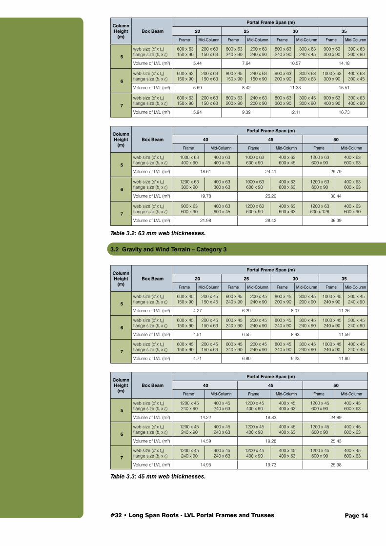
3.2 Gravity and Wind Terrain – Category 3
Column Height
(m)Box Beam
Portal Frame Span (m)
20 25 30 35
Frame Mid-Column Frame Mid-Column Frame Mid-Column Frame Mid-Column
5
web size (d x tw) flange size (bf x tf)
600 x 45 150 x 90
200 x 45 150 x 45
600 x 45 240 x 90
200 x 45 240 x 90
800 x 45 200 x 90
300 x 45 200 x 90
1000 x 45 240 x 90
300 x 45 240 x 90
Volume of LVL (m3) 4.27 6.29 8.07 11.26
6
web size (d x tw) flange size (bf x tf)
600 x 45 150 x 90
200 x 45 150 x 63
600 x 45 240 x 90
200 x 45 240 x 90
800 x 45 240 x 90
300 x 45 240 x 90
1000 x 45 240 x 90
300 x 45 240 x 90
Volume of LVL (m3) 4.51 6.55 8.93 11.59
7
web size (d x tw) flange size (bf x tf)
600 x 45 150 x 90
200 x 45 150 x 63
600 x 45 240 x 90
200 x 45 240 x 90
800 x 45 240 x 90
300 x 45 240 x 90
1000 x 45 240 x 90
400 x 45 240 x 45
Volume of LVL (m3) 4.71 6.80 9.23 11.80
Column Height
(m)Box Beam
Portal Frame Span (m)
40 45 50
Frame Mid-Column Frame Mid-Column Frame Mid-Column
5
web size (d x tw) flange size (bf x tf)
1200 x 45 240 x 90
400 x 45 240 x 63
1200 x 45 400 x 90
400 x 45 400 x 63
1200 x 45 600 x 90
400 x 45 600 x 63
Volume of LVL (m3) 14.22 18.83 24.89
6
web size (d x tw) flange size (bf x tf)
1200 x 45 240 x 90
400 x 45 240 x 63
1200 x 45 400 x 90
400 x 45 400 x 63
1200 x 45 600 x 90
400 x 45 600 x 63
Volume of LVL (m3) 14.59 19.28 25.43
7
web size (d x tw) flange size (bf x tf)
1200 x 45 240 x 90
400 x 45 240 x 63
1200 x 45 400 x 90
400 x 45 400 x 63
1200 x 45 600 x 90
400 x 45 600 x 63
Volume of LVL (m3) 14.95 19.73 25.98
Table 3.3: 45 mm web thicknesses.

#32 • Long Span Roofs - LVL Portal Frames and Trusses Page 15
Column Height
(m)Box Beam
Portal Frame Span (m)
20 25 30 35
Frame Mid-Column Frame Mid-Column Frame Mid-Column Frame Mid-Column
5
web size (d x tw) flange size (bf x tf)
400 x 63 240 x 90
200 x 63 240 x 45
600 x 63 200 x 90
200 x 63 200 x 90
800 x 63 200 x 90
300 x 63 200 x 45
800 x 63 300 x 90
300 x 63 300 x 63
Volume of LVL (m3) 5.01 7.16 10.03 13.03
6
web size (d x tw) flange size (bf x tf)
600 x 63 150 x 90
200 x 63 150 x 45
600 x 63 200 x 90
200 x 63 200 x 90
800 x 63 200 x 90
300 x 63 200 x 45
800 x 63 300 x 90
300 x 63 300 x 63
Volume of LVL (m3) 5.65 7.44 10.36 13.42
7
web size (d x tw) flange size (bf x tf)
600 x 63 150 x 90
200 x 63 150 x 45
600 x 63 200 x 90
200 x 63 200 x 90
800 x 63 200 x 90
300 x 63 200 x 45
800 x 63 300 x 90
300 x 63 300 x 90
Volume of LVL (m3) 5.89 7.73 10.69 13.97
Column Height
(m)Box Beam
Portal Frame Span (m)
40 45 50
Frame Mid-Column Frame Mid-Column Frame Mid-Column
5
web size (d x tw) flange size (bf x tf)
1000 x 63 300 x 90
400 x 63 300 x 45
1200 x 63 300 x 90
400 x 63 300 x 63
1000 x 63 600 x 90
400 x 63 600 x 45
Volume of LVL (m3) 16.91 21.38 26.81
6
web size (d x tw) flange size (bf x tf)
1000 x 63 300 x 90
400 x 63 300 x 45
1200 x 63 300 x 90
400 x 63 300 x 90
1000 x 63 600 x 90
400 x 63 600 x 45
Volume of LVL (m3) 17.35 22.04 27.38
7
web size (d x tw) flange size (bf x tf)
1000 x 63 300 x 90
400 x 63 300 x 45
1200 x 63 300 x 90
400 x 63 300 x 90
1000 x 63 600 x 90
400 x 63 600 x 45
Volume of LVL (m3) 17.79 22.55 27.95
Table 3.4: 63 mm web thicknesses.
#32 • Long Span Roofs - LVL Portal Frames and Trusses Page 16
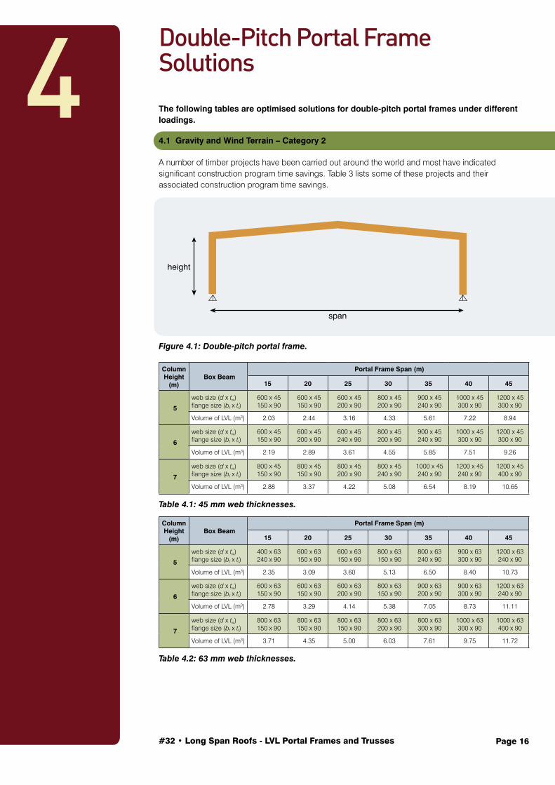
The following tables are optimised solutions for double-pitch portal frames under different loadings.
4.1 Gravity and Wind Terrain – Category 2
A number of timber projects have been carried out around the world and most have indicated significant construction program time savings. Table 3 lists some of these projects and their associated construction program time savings.
Figure 4.1: Double-pitch portal frame.
Column Height
(m)Box Beam
Portal Frame Span (m)
15 20 25 30 35 40 45
5
web size (d x tw) flange size (bf x tf)
600 x 45 150 x 90
600 x 45 150 x 90
600 x 45 200 x 90
800 x 45 200 x 90
900 x 45 240 x 90
1000 x 45 300 x 90
1200 x 45 300 x 90
Volume of LVL (m3) 2.03 2.44 3.16 4.33 5.61 7.22 8.94
6
web size (d x tw) flange size (bf x tf)
600 x 45 150 x 90
600 x 45 200 x 90
600 x 45 240 x 90
800 x 45 200 x 90
900 x 45 240 x 90
1000 x 45 300 x 90
1200 x 45 300 x 90
Volume of LVL (m3) 2.19 2.89 3.61 4.55 5.85 7.51 9.26
7
web size (d x tw) flange size (bf x tf)
800 x 45 150 x 90
800 x 45 150 x 90
800 x 45 200 x 90
800 x 45 240 x 90
1000 x 45 240 x 90
1200 x 45 240 x 90
1200 x 45 400 x 90
Volume of LVL (m3) 2.88 3.37 4.22 5.08 6.54 8.19 10.65
Table 4.1: 45 mm web thicknesses.
Column Height
(m)Box Beam
Portal Frame Span (m)
15 20 25 30 35 40 45
5
web size (d x tw) flange size (bf x tf)
400 x 63 240 x 90
600 x 63 150 x 90
600 x 63 150 x 90
800 x 63 150 x 90
800 x 63 240 x 90
900 x 63 300 x 90
1200 x 63 240 x 90
Volume of LVL (m3) 2.35 3.09 3.60 5.13 6.50 8.40 10.73
6
web size (d x tw) flange size (bf x tf)
600 x 63 150 x 90
600 x 63 150 x 90
600 x 63 200 x 90
800 x 63 150 x 90
900 x 63 200 x 90
900 x 63 300 x 90
1200 x 63 240 x 90
Volume of LVL (m3) 2.78 3.29 4.14 5.38 7.05 8.73 11.11
7
web size (d x tw) flange size (bf x tf)
800 x 63 150 x 90
800 x 63 150 x 90
800 x 63 150 x 90
800 x 63 200 x 90
800 x 63 300 x 90
1000 x 63 300 x 90
1000 x 63 400 x 90
Volume of LVL (m3) 3.71 4.35 5.00 6.03 7.61 9.75 11.72
Table 4.2: 63 mm web thicknesses.
4Double-Pitch Portal Frame Solutions
height
span

#32 • Long Span Roofs - LVL Portal Frames and Trusses Page 17
4.2 Gravity and Wind Terrain – Category 3
Column Height
(m)Box Beam
Portal Frame Span (m)
15 20 25 30 35 40 45
5
web size (d x tw) flange size (bf x tf)
400 x 45 200 x 90
600 x 45 150 x 90
600 x 45 150 x 90
800 x 45 150 x 90
800 x 45 240 x 90
1000 x 45 240 x 90
1200 x 45 240 x 90
Volume of LVL (m3) 1.80 2.44 2.84 3.97 5.20 6.68 8.34
6
web size (d x tw) flange size (bf x tf)
600 x 45 150 x 90
600 x 45 150 x 90
600 x 45 150 x 90
800 x 45 150 x 90
800 x 45 240 x 90
1000 x 45 240 x 90
1200 x 45 240 x 90
Volume of LVL (m3) 2.19 2.60 3.00 4.17 5.43 6.95 8.64
7
web size (d x tw) flange size (bf x tf)
600 x 45 240 x 90
800 x 45 150 x 90
800 x 45 150 x 90
800 x 45 150 x 90
800 x 45 240 x 90
1000 x 45 240 x 90
1200 x 45 240 x 90
Volume of LVL (m3) 2.82 3.37 3.87 4.37 5.66 7.21 8.95
Table 4.3: 45 mm web thicknesses.
Column Height
(m)Box Beam
Portal Frame Span (m)
15 20 25 30 35 40 45
5
web size (d x tw) flange size (bf x tf)
400 x 63 150 x 90
400 x 63 240 x 90
600 x 63 150 x 90
800 x 63 240 x 90
800 x 63 200 x 90
800 x 63 300 x 90
1000 x 63 300 x 90
Volume of LVL (m3) 1.94 2.82 3.60 4.77 6.17 7.76 9.93
6
web size (d x tw) flange size (bf x tf)
600 x 63 150 x 90
600 x 63 150 x 90
600 x 63 150 x 90
800 x 63 150 x 90
800 x 63 200 x 90
800 x 63 300 x 90
1000 x 63 300 x 90
Volume of LVL (m3) 2.78 3.29 3.81 5.38 6.45 8.07 10.29
7
web size (d x tw) flange size (bf x tf)
600 x 63 200 x 90
600 x 63 240 x 90
800 x 63 150 x 90
800 x 63 150 x 90
800 x 63 200 x 90
900 x 63 240 x 90
1000 x 63 300 x 90
Volume of LVL (m3) 3.24 4.05 5.00 5.64 6.72 8.48 10.65
Table 4.4: 63 mm web thicknesses.
Note:
1. The volume of LVL shown is the volume required for constructing one whole double-pitch portal frame, which includes the rafters and two columns, see diagram on the upper corner for clarification.
2. The unit for web size and flange size are millimetres (mm).

#32 • Long Span Roofs - LVL Portal Frames and Trusses Page 18
The optimised solutions for each truss span under different loadings are presented in this Section.
5.1 Gravity and Wind Terrain – Category 2
A number of timber projects have been carried out around the world and most have indicated significant construction program time savings. Table 3 lists some of these projects and their associated construction program time savings.
Figure 5.1: 50 m span.
Figure 5.2: 60 m span.
5Truss Solutions

#32 • Long Span Roofs - LVL Portal Frames and Trusses Page 19
Figure 5.3: 70 m span
5.2 Gravity and Wind Terrain – Category 3
Figure 5.4: 50 m span.

#32 • Long Span Roofs - LVL Portal Frames and Trusses Page 20
Figure 5.5: 60 m span.
Figure 5.6: 70 m span.

#32 • Long Span Roofs - LVL Portal Frames and Trusses Page 21
6.1 Portal Frames
6.1.1 Double-Pitch Portal Frame
Governing factor
For small spans (15 m, 20 m) of portal frame design, the lateral deflection at the column top governs the design. Final solutions provided for the portal frames have a column top deflection at around 38 mm to 40 mm, where the lateral deflection limit is 40 mm. Cross sections that satisfy the deflection limits exceed the bending and axial load capacity requirements by a large margin, especially for portal frames with the greater clear heights.
For medium spans (25 m, 30 m, and 35 m), the gravity plus wind minimum uplift loading condition is most critical and governs the design, closely followed by the gravity plus live loading condition. Lateral deflection at the top of the column is no longer critical as larger sections are now being used (depth greater than 900 mm), and the box section that is able to resist the required loading is always sufficiently by stiff to resist the lateral deflection.
When the spans are increased to 40 metres and 45 metres, the rafters are now very long and become quite heavy. The mid-span gravity deflection becomes the most critical and governs the design.
Slenderness and load carrying capacity
In 15 and 20 m spans, where the loads are relatively small and the lateral deflection from wind is critical, very slender box sections such as 600 x 63 by 20 x 90, 800 x 63, 20 x 90, 900 x 45 and 20 x 90 are able to provide sufficient strength capacities. But when the spans get larger (30 m, 35 m, 40 m and 45 m), very slender sections must be avoided, since the loads are now getting quite large and very slender sections are not able to provide sufficient load carrying capacities. It is not unusual that some less slender box sections, even with a smaller total cross sectional area, would have a larger load carrying capacity than a cross section that has a larger cross sectional area but more slender.
Effectiveness of increasing dimensions
The following observations can be made. One can conclude that the greater the depth of the box section, the smaller the deflections. Another conclusion possible is that the wider the box section, the greater the load carrying capacity. However, increasing the width of a box section helps relatively little in reducing the deflection. Increasing the depth of a box section also helps to increase the load carrying capacity, but increasing the width is more effective at increasing load carrying capacity as the lateral stability governs the moment resistance in most cases.
Compression in rafters and columns
One can note that for smaller spans (15 m to 35 m), the compression force in the columns is greater than in the rafters. But in larger spans (40 m and 45 m), the compression force in the rafter is greater than in the columns. This is because in smaller spans, the compression force due to the gravity downward/supporting effect in the columns is greater than the mid span pressing effect in the rafter minus the relieving effect caused by the upward pointing 5° degrees roof pitch. But in larger spans, due to the huge mid span downward forces in the rafter, the pressing effect minus the relieving effect caused by the upward pointing 5° degrees roof pitch in the rafter is now greater than the gravity downward/supporting effect in the columns. Therefore, the compression force in the rafter is now greater than the compression force in the columns. Suggestions to reduce the deflection and compression force in the rafter would be to use a steeper roof pitch or increase the pre-camber in the rafter.
6Summary of Trends and Findings
#32 • Long Span Roofs - LVL Portal Frames and Trusses Page 22
Critical loads
Comparing the critical loads that govern the designs between the different Wind Terrain Categories: in Terrain Category 2, wind load governs the design for spans from 15 metres to 25 metres. In Terrain Category 3, wind load governs the design for spans from 15 metres to 20 metres and also in the 7 metres clear height designs.
In all others spans, gravity load governs the design. This indicates that gravity load governs most designs in long span timber portal frame design, especially for spans greater than 20 metres. When designing long span LVL portal frames the gravity loads should be calculated precisely and never be underestimated.
Comparison between 45 mm and 63 mm web thicknesses
Results from the solution tables show that for the same span and height, box sections with 45 mm web thicknesses use less volume of LVL than the 63 mm web thicknesses box sections. This indicates that the 45 mm web thickness box sections are more efficient than the 63 millimetres web thicknesses box sections.
Cross sectional area
This Guide uses web thicknesses of 45 mm or 63 mm and flange thicknesses of 90 mm as the starting thicknesses in design.
The flange thickness is increased if needed. Since the web thicknesses are always thinner than the flange thicknesses, increasing the depth of the box section will result in a smaller increase in cross sectional area than increasing the width of the box section. Therefore, when it is necessary to increase the box section size, try increasing the depth first, before increasing the width. Some 1200 mm depth sections have a smaller total area than a 1000 mm depth section. One should not be surprised when seeing a solution of a larger span or greater height that has a smaller depth. Use the cross sectional area supporting table to compare and use the smallest section that can provide the required ultimate and serviceability capacity.
6.1.2 Internal Propped Portal Frame and Comparison
Mid-span deflection
Since there is an inner column at the centre of the roof, the deflection at the apex joint does not occur. For internal propped portal frames, the vertical deflections are measured at mid span of each of the rafters.
Compression force in the columns
It is found that the compression force in the inner column is greater than the side columns. This is because the inner column supports a greater contributory area than the side columns.
Trends
The trends found from the internal propped portal frame results are similar to the double-pitch portal frame results, except for the following differences.
Comparison of individual spans
Comparing internal propped and double-pitch solutions for the same clear span, internal propped solutions require larger size of sections than double-pitch solutions. This is because the rafter of the internal propped portal frames are straight within each span, and do not have the upward pointing that double-pitch portal frames have at mid span to reduce the force and the deflection.
Comparison of total structure spans
Comparing results of two times the internal propped spans with the double-pitch span, the internal propped solutions use smaller cross sections and smaller volumes of LVL. This indicates that for the same total span, internal propped portal frame is more efficient than double-pitch portal frame. If architecturally allowed, internal propped portal frames are a more efficient option to be used.

#32 • Long Span Roofs - LVL Portal Frames and Trusses Page 23
6.2 Trusses
6.2.1 Thicknesses
For the 50 metre and 60 metre span trusses, 135 mm thick solid sections of LVL are sufficient to provide the required strengths and deformation performances. However, the 135 mm thick solid sections are not able to provide sufficient strength for the 70 m trusses, even with the use of T stiffeners. As a result, all 70 metres trusses use 180 mm thick solid sections. It is assumed that the LVL solid sections are fabricated from layers of 45 mm thick LVL sections. However, in the design of T stiffeners both 45 mm and 63 mm thicknesses are used.
6.2.2 Effect of T Stiffener on Compression and Tension Capacities
T stiffeners are useful for increasing the compression capacity of the truss members only and do not contribute to resisting tension forces. When both compression and tension forces have exceeded the capacity of a member, the compression force may be overcome by the addition of a T stiffener, but the tension force is still exceeding the capacity. This can only be resolved by increasing the size of the section.
6.2.3 Top Chord
The top chords are governed by tension forces caused by the upward wind forces. It is assumed that the top chords are laterally restrained by the purlins. As a result, the compression capacity will always be sufficient to take the compression loads. But the tension capacity is independent to the lateral restraints. Therefore, the top chords are governed by tension.
6.2.4 Bottom Chord
The outer sections of the bottom chords carry the largest compression forces, especially when the wind is blowing downwards. This is because they transfer all the forces from the truss to the columns. For the same reason, the outer sections of the bottom chord also carry the largest tension forces when the wind is blowing upwards. Since all truss members can have different depths but they must have the same thicknesses for efficiency of load transfer at the connections, the outer sections of the bottom chord are always the critical member for deciding the thickness of the whole truss.

Page 24#32 • Long Span Roofs - LVL Portal Frames and Trusses
This is a spreadsheet example for Wind Load Calculations. The n values are provided in Section 8 - Supporting Materials for Portal Frames.
n = 0.5 x ρair x Vdes,θ2 x Cdyn x 103
Pressure = n x Cfig (kPa)
For this double-pitch portal frame example, the n value is taken from Section 8.2. The n values provided in this Guide are for wind loads of Terrain Category 1. In order to convert the wind loads to Terrain Category 2 or Terrain Category 3, one will need to multiply the pressures by the ratio table provided in Section 8.
Section 7 Example A: Wind Load Calculation
Building ElementWindward wall - to - 0.7 0.8 0.56 0.7 0.8 0.56 1.449 0.00 0.00Leeward wall - to - -0.5 0.8 -0.4 0.7 0.8 0.56 1.449 -1.39 -11.13Sidewalls 0.000 to 7.984 -0.65 0.8 -0.52 0.7 0.8 0.56 1.449 -1.56 -12.52Sidewalls 7.984 to 15.968 -0.5 0.8 -0.4 0.7 0.8 0.56 1.449 -1.39 -11.13Sidewalls 15.968 to 23.952 -0.3 0.8 -0.24 0.7 0.8 0.56 1.449 -1.16 -9.27Sidewalls 23.952 to onwards ~ -0.2 0.8 -0.16 0.7 0.8 0.56 1.449 -1.04 -8.35Roof 0.000 to 3.992 -0.9 0.8 -0.72 0.7 0.8 0.56 1.449 -1.85 -14.84Roof 3.992 to 7.984 -0.9 0.8 -0.72 0.7 0.8 0.56 1.449 -1.85 -14.84Roof 7.984 to 15.968 -0.5 0.8 -0.4 0.7 0.8 0.56 1.449 -1.39 -11.13Roof 15.968 to 23.952 -0.3 0.8 -0.24 0.7 0.8 0.56 1.449 -1.16 -9.27Roof 23.952 to onwards ~ -0.2 0.8 -0.16 0.7 0.8 0.56 1.449 -1.04 -8.35
Distance from windward edge (m) Cpe Ka Kc,e K l Kp Cfig,e Cpi Kc,i Cfig,i 0.5 ρairVdes,θ2 Cdyn x 10-3 P (kPa) UDL at 8 m spacings
Building ElementWindward wall - to - 0.7 0.8 0.56 -0.65 0.8 -0.52 1.449 1.56 12.52Leeward wall - to - -0.2 0.8 -0.16 -0.65 0.8 -0.52 1.449 0.52 4.17Sidewalls 0.000 to 7.984 -0.65 0.8 -0.52 -0.65 0.8 -0.52 1.449 0.00 0.00Sidewalls 7.984 to 15.968 -0.5 0.8 -0.4 -0.65 0.8 -0.52 1.449 0.17 1.39Sidewalls 15.968 to 23.952 -0.3 0.8 -0.24 -0.65 0.8 -0.52 1.449 0.41 3.25Sidewalls 23.952 to onwards ~ -0.2 0.8 -0.16 -0.65 0.8 -0.52 1.449 0.52 4.17Roof 0.000 to 3.992 -0.4 0.8 -0.32 -0.65 0.8 -0.52 1.449 0.29 2.32Roof 3.992 to 7.984 -0.4 0.8 -0.32 -0.65 0.8 -0.52 1.449 0.29 2.32Roof 7.984 to 15.968 0 0.8 0 -0.65 0.8 -0.52 1.449 0.75 6.03Roof 15.968 to 23.952 0.1 0.8 0.08 -0.65 0.8 -0.52 1.449 0.87 6.96Roof 23.952 to onwards ~ 0.2 0.8 0.16 -0.65 0.8 -0.52 1.449 0.99 7.88
Distance from windward edge (m) Cpe Ka Kc,e K l Kp Cfig,e Cpi Kc,i Cfig,i 0.5 ρairVdes,θ2 Cdyn x 10-3 P (kPa) UDL at 8 m spacings
Table 7.1: Wind across (maximum uplift). roof angle = 5° h = 7.984 m L = 45 m
Table 7.2: Wind across (minimum uplift). roof angle = 5° h = 7.984 m L = 45 m

#32 • Long Span Roofs - LVL Portal Frames and Trusses Page 25
Please see Example A in Section 7 for how to use the n values provided in this section.
8.1 Internal Propped Portal Frame Wind Pressures and Ratios
8Supporting Materials – Portal Frames
Table 8.1: Internal propped portal frame – Wind Terrain Category 1 pressures.
Note:
n = 0.5 x ρair x Vdes,θ2 x Cdyn x 103
Pressure = n x Cfig (kPa)
For Importance Level 3 structures in Region A6 only.
Table 8.2: Internal propped portal frame – Wind Terrain Category 2 pressures.
Note:
n = 0.5 x ρair x Vdes,θ2 x Cdyn x 103
Pressure = n x Cfig (kPa)
For Importance Level 3 structures in Region A6 only.
TC1
TC1
TC1
10 m 15 m 20 m
z M z,cat n z M z,cat n z M z,cat n
Height(m)
Height(m)
Height(m)
5 5.437 1.056 1.416 5.656 1.059 1.424 5.875 1.062 1.4326 6.437 1.070 1.454 6.656 1.073 1.462 6.875 1.076 1.477 7.437 1.084 1.492 7.656 1.087 1.5 7.875 1.090 1.508
25 m 30 m 35 mz M z,cat n z M z,cat n z M z,cat n
5 6.094 1.065 1.44 6.312 1.068 1.448 6.531 1.071 1.4566 7.094 1.079 1.478 7.312 1.082 1.486 7.531 1.085 1.4957 8.094 1.093 1.517 8.312 1.096 1.525 8.531 1.099 1.533
40 m 45 m 50 mz M z,cat n z M z,cat n z M z,cat n
5 6.750 1.074 1.464 6.968 1.078 1.475 7.187 1.081 1.4846 7.750 1.088 1.503 7.968 1.092 1.514 8.187 1.095 1.5227 8.750 1.102 1.542 8.968 1.106 1.553 9.187 1.109 1.561
TC210 m 15 m 20 m
z M z,cat n z M z,cat n z M z,cat n5 5.437 0.918 1.07 5.656 0.922 1.079 5.875 0.926 1.0896 6.437 0.936 1.112 6.656 0.940 1.122 6.875 0.944 1.1317 7.437 0.954 1.155 7.656 0.958 1.165 7.875 0.962 1.175
TC225 m 30 m 35 m
z M z,cat n z M z,cat n z M z,cat n5 6.094 0.930 1.098 6.312 0.934 1.108 6.531 0.938 1.1176 7.094 0.948 1.141 7.312 0.952 1.151 7.531 0.956 1.167 8.094 0.966 1.185 8.312 0.970 1.195 8.531 0.974 1.204
TC240 m 45 m 50 m
z M z,cat n z M z,cat n z M z,cat n
Height (m)
Height (m)
Height (m)
5 6.750 0.941 1.124 6.968 0.945 1.134 7.187 0.949 1.1436 7.750 0.959 1.168 7.968 0.963 1.177 8.187 0.967 1.1877 8.750 0.977 1.212 8.968 0.981 1.222 9.187 0.985 1.232

#32 • Long Span Roofs - LVL Portal Frames and Trusses Page 26
TC2/TC1 ratio10 m 15 m 20 m 25 m 30 m
z ratio z ratio z ratio z ratio z ratio
Height(m)
Height(m)
Height(m)
Height(m)
5 5.437 0.756 5.656 0.758 5.875 0.760 6.094 0.763 6.312 0.7656 6.437 0.765 6.656 0.767 6.875 0.769 7.094 0.772 7.312 0.7757 7.437 0.774 7.656 0.777 7.875 0.779 8.094 0.781 8.312 0.784
TC2/TC1 ratio35 m 40 m 45 m 50 m
z ratio z ratio z ratio z ratio5 6.531 0.767 6.750 0.768 6.968 0.769 7.187 0.7706 7.531 0.776 7.750 0.777 7.968 0.777 8.187 0.7807 8.531 0.785 8.750 0.786 8.968 0.787 9.187 0.789
TC3/TC1 ratio10 m 15 m 20 m 25 m 30 m
z ratio z ratio z ratio z ratio z ratio5 5.437 0.618 5.656 0.614 5.875 0.611 6.094 0.608 6.312 0.6046 6.437 0.602 6.656 0.598 6.875 0.595 7.094 0.592 7.312 0.5897 7.437 0.586 7.656 0.583 7.875 0.580 8.094 0.577 8.312 0.574
TC3/TC1 ratio35 m 40 m 45 m 50 m
z ratio z ratio z ratio z ratio5 6.531 0.601 6.750 0.598 6.968 0.593 7.187 0.5906 7.531 0.585 7.750 0.582 7.968 0.578 8.187 0.5757 8.531 0.571 8.750 0.567 8.968 0.563 9.187 0.561
Table 8.3: Internal propped portal frame – Wind Terrain Category 3 pressures
Note:
n = 0.5 x ρair x Vdes,θ2 x Cdyn x 103
Pressure = n x Cfig (kPa)
For Importance Level 3 structures in Region A6 only.
Table 8.4: Internal propped portal frame wind pressures – ratio between Terrain Category 2 & Terrain Category 1.
Table 8.5: Internal propped portal frame wind pressures – ratio between Terrain Category 3 & Terrain Category 1.
TC310 m 15 m 20 m
z M z,cat n z M z,cat n z M z,cat n5 5.437 0.830 0.875 5.656 0.830 0.875 5.875 0.830 0.8756 6.437 0.830 0.875 6.656 0.830 0.875 6.875 0.830 0.8757 7.437 0.830 0.875 7.656 0.830 0.875 7.875 0.830 0.875
TC325 m 30 m 35 m
z M z,cat n z M z,cat n z M z,cat n5 6.094 0.830 0.875 6.312 0.830 0.875 6.531 0.830 0.8756 7.094 0.830 0.875 7.312 0.830 0.875 7.531 0.830 0.8757 8.094 0.830 0.875 8.312 0.830 0.875 8.531 0.830 0.875
TC340 m 45 m 50 m
z M z,cat n z M z,cat n z M z,cat n
Height(m)
Height(m)
Height(m)
5 6.750 0.830 0.875 6.968 0.830 0.875 7.187 0.830 0.8756 7.750 0.830 0.875 7.968 0.830 0.875 8.187 0.830 0.8757 8.750 0.830 0.875 8.968 0.830 0.875 9.187 0.830 0.875
#32 • Long Span Roofs - LVL Portal Frames and Trusses Page 27
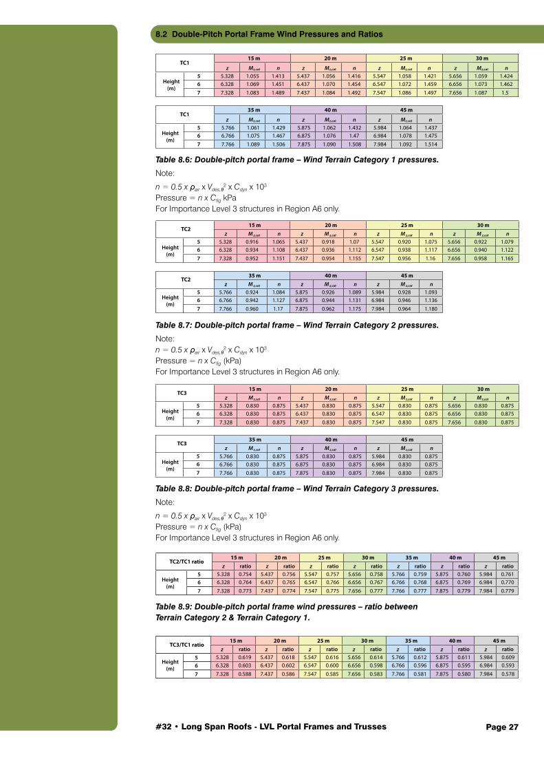
Table 8.6: Double-pitch portal frame – Wind Terrain Category 1 pressures.
Note:
n = 0.5 x ρair x Vdes,θ2 x Cdyn x 103
Pressure = n x Cfig kPaFor Importance Level 3 structures in Region A6 only.
Table 8.7: Double-pitch portal frame – Wind Terrain Category 2 pressures.
Note:n = 0.5 x ρair x Vdes,θ
2 x Cdyn x 103
Pressure = n x Cfig (kPa)For Importance Level 3 structures in Region A6 only.
Table 8.8: Double-pitch portal frame – Wind Terrain Category 3 pressures.
Note:
n = 0.5 x ρair x Vdes,θ2 x Cdyn x 103
Pressure = n x Cfig (kPa)For Importance Level 3 structures in Region A6 only.
Height(m)
Height(m)
Height(m)
Height(m)
TC115 m 20 m 25 m 30 m
z M z,cat n z M z,cat n z M z,cat n z M z,cat n5 5.328 1.055 1.413 5.437 1.056 1.416 5.547 1.058 1.421 5.656 1.059 1.4246 6.328 1.069 1.451 6.437 1.070 1.454 6.547 1.072 1.459 6.656 1.073 1.4627 7.328 1.083 1.489 7.437 1.084 1.492 7.547 1.086 1.497 7.656 1.087 1.5
TC135 m 40 m 45 m
z M z,cat n z M z,cat n z M z,cat n5 5.766 1.061 1.429 5.875 1.062 1.432 5.984 1.064 1.4376 6.766 1.075 1.467 6.875 1.076 1.47 6.984 1.078 1.4757 7.766 1.089 1.506 7.875 1.090 1.508 7.984 1.092 1.514
TC215 m 20 m 25 m 30 m
z M z,cat n z M z,cat n z M z,cat n z M z,cat n5 5.328 0.916 1.065 5.437 0.918 1.07 5.547 0.920 1.075 5.656 0.922 1.0796 6.328 0.934 1.108 6.437 0.936 1.112 6.547 0.938 1.117 6.656 0.940 1.1227 7.328 0.952 1.151 7.437 0.954 1.155 7.547 0.956 1.16 7.656 0.958 1.165
TC235 m 40 m 45 m
z M z,cat n z M z,cat n z M z,cat n5 5.766 0.924 1.084 5.875 0.926 1.089 5.984 0.928 1.0936 6.766 0.942 1.127 6.875 0.944 1.131 6.984 0.946 1.1367 7.766 0.960 1.17 7.875 0.962 1.175 7.984 0.964 1.180
Height(m)
Height(m)
Height(m)
Height(m)
TC315 m 20 m 25 m 30 m
z M z,cat n z M z,cat n z M z,cat n z M z,cat n5 5.328 0.830 0.875 5.437 0.830 0.875 5.547 0.830 0.875 5.656 0.830 0.8756 6.328 0.830 0.875 6.437 0.830 0.875 6.547 0.830 0.875 6.656 0.830 0.8757 7.328 0.830 0.875 7.437 0.830 0.875 7.547 0.830 0.875 7.656 0.830 0.875
TC335 m 40 m 45 m
z M z,cat n z M z,cat n z M z,cat n5 5.766 0.830 0.875 5.875 0.830 0.875 5.984 0.830 0.8756 6.766 0.830 0.875 6.875 0.830 0.875 6.984 0.830 0.8757 7.766 0.830 0.875 7.875 0.830 0.875 7.984 0.830 0.875
TC2/TC1 ratio15 m 20 m 25 m 30 m 35 m 40 m 45 m
z ratio z ratio z ratio z ratio z ratio z ratio z ratio5 5.328 0.754 5.437 0.756 5.547 0.757 5.656 0.758 5.766 0.759 5.875 0.760 5.984 0.7616 6.328 0.764 6.437 0.765 6.547 0.766 6.656 0.767 6.766 0.768 6.875 0.769 6.984 0.770
7 7.328 0.773 7.437 0.774 7.547 0.775 7.656 0.777 7.766 0.777 7.875 0.779 7.984 0.779
TC3/TC1 ratio15 m 20 m 25 m 30 m 35 m 40 m 45 m
z ratio z ratio z ratio z ratio z ratio z ratio z ratio5 5.328 0.619 5.437 0.618 5.547 0.616 5.656 0.614 5.766 0.612 5.875 0.611 5.984 0.6096 6.328 0.603 6.437 0.602 6.547 0.600 6.656 0.598 6.766 0.596 6.875 0.595 6.984 0.593
7 7.328 0.588 7.437 0.586 7.547 0.585 7.656 0.583 7.766 0.581 7.875 0.580 7.984 0.578
Height(m)
Height(m)
Height(m)
Height(m)
TC315 m 20 m 25 m 30 m
z M z,cat n z M z,cat n z M z,cat n z M z,cat n5 5.328 0.830 0.875 5.437 0.830 0.875 5.547 0.830 0.875 5.656 0.830 0.8756 6.328 0.830 0.875 6.437 0.830 0.875 6.547 0.830 0.875 6.656 0.830 0.8757 7.328 0.830 0.875 7.437 0.830 0.875 7.547 0.830 0.875 7.656 0.830 0.875
TC335 m 40 m 45 m
z M z,cat n z M z,cat n z M z,cat n5 5.766 0.830 0.875 5.875 0.830 0.875 5.984 0.830 0.8756 6.766 0.830 0.875 6.875 0.830 0.875 6.984 0.830 0.8757 7.766 0.830 0.875 7.875 0.830 0.875 7.984 0.830 0.875
TC2/TC1 ratio15 m 20 m 25 m 30 m 35 m 40 m 45 m
z ratio z ratio z ratio z ratio z ratio z ratio z ratio5 5.328 0.754 5.437 0.756 5.547 0.757 5.656 0.758 5.766 0.759 5.875 0.760 5.984 0.7616 6.328 0.764 6.437 0.765 6.547 0.766 6.656 0.767 6.766 0.768 6.875 0.769 6.984 0.770
7 7.328 0.773 7.437 0.774 7.547 0.775 7.656 0.777 7.766 0.777 7.875 0.779 7.984 0.779
TC3/TC1 ratio15 m 20 m 25 m 30 m 35 m 40 m 45 m
z ratio z ratio z ratio z ratio z ratio z ratio z ratio5 5.328 0.619 5.437 0.618 5.547 0.616 5.656 0.614 5.766 0.612 5.875 0.611 5.984 0.6096 6.328 0.603 6.437 0.602 6.547 0.600 6.656 0.598 6.766 0.596 6.875 0.595 6.984 0.593
7 7.328 0.588 7.437 0.586 7.547 0.585 7.656 0.583 7.766 0.581 7.875 0.580 7.984 0.578
8.2 Double-Pitch Portal Frame Wind Pressures and Ratios
Table 8.9: Double-pitch portal frame wind pressures – ratio between Terrain Category 2 & Terrain Category 1.

#32 • Long Span Roofs - LVL Portal Frames and Trusses Page 28
8.3 Flange Width Selection to Minimise Wastage
In order to minimise wastage of LVL in a project, the design flange width (bf) of the box sections considered in this Guide are ones that can be equally cut from a 1200 mm LVL billet. Therefore, the flange width (bf) of a box section can be selected from the following two tables:
2 Acoustic performance was assessed by PKA Acoustic Consulting
Starting size (mm) Cut into No. of pieces Flange width, bf (mm)
1200 1 1200
1200 2 600
1200 3 400
1200 4 300
1200 5 240
1200 6 200
1200 8 150
bf (mm)Total width = bf + 2 x web thicknesses t w (mm)
tw = 45 mm tw = 63 mm
150 240 276
200 290 326
240 330 366
300 390 426
400 490 526
600 690 726
d (mm)
tw (mm)
bf (mm)
t f (mm)
A (m2)
I (m4)
d (mm)
t w (mm)
bf (mm)
t f (mm)
A (m2)
I (m4)
d (mm)
t w (mm)
bf (mm)
t f (mm)
A (m2)
I (m4)
400 45 150 90 0.0630 0.0011 600 45 150 90 0.810 0.00339 800 45 150 90 0.0990 0.0073
400 45 200 90 0.0720 0.0014 600 45 200 90 0.0900 0.00399 800 45 200 90 0.1080 0.0084
400 45 240 90 0.0792 0.0015 600 45 240 90 0.0972 0.00446 800 45 240 90 0.1152 0.0093
400 45 300 90 0.0900 0.0018 600 45 300 90 0.1080 0.00517 800 45 300 90 0.1260 0.0107
400 45 400 90 0.1080 0.0023 600 45 400 90 0.1260 0.00635 800 45 400 90 0.1440 0.0130
400 45 600 90 0.1440 0.0031 600 45 600 90 0.1620 0.00872 800 45 600 90 0.1800 0.0175
d (mm)
tw (mm)
bf (mm)
t f (mm)
A (m2)
I (m4)
d (mm)
t w (mm)
bf (mm)
t f (mm)
A (m2)
I (m4)
d (mm)
t w (mm)
bf (mm)
t f (mm)
A (m2)
I (m4)
900 45 150 90 0.1080 0.00991 1000 45 150 90 0.1170 0.0131 1200 45 150 90 0.1350 0.02129
900 45 200 90 0.1170 0.01140 1000 45 200 90 0.1260 0.0150 1200 45 200 90 0.1440 0.02407
900 45 240 90 0.1242 0.01258 1000 45 240 90 0.1332 0.0165 1200 45 240 90 0.1512 0.02630
900 45 300 90 0.1350 0.01436 1000 45 300 90 0.1440 0.0187 1200 45 300 90 0.1620 0.02963
900 45 400 90 0.1530 0.01733 1000 45 400 90 0.1620 0.0225 1200 45 400 90 0.1800 0.03519
900 45 600 90 0.1890 0.02326 1000 45 600 90 0.1980 0.0299 1200 45 600 90 0.2160 0.04630
d (mm)
tw (mm)
bf (mm)
t f (mm)
A (m2)
I (m4)
d (mm)
t w (mm)
bf (mm)
t f (mm)
A (m2)
I (m4)
d (mm)
t w (mm)
bf (mm)
t f (mm)
A (m2)
I (m4)
1200 45 150 126 0.1458 0.02391 1200 45 150 180 0.1620 0.02715 1200 45 150 270 0.1890 0.03097
1200 45 200 126 0.1584 0.02756 1200 45 200 180 0.1800 0.03188 1200 45 200 270 0.2160 0.03697
1200 45 240 126 0.1685 0.03048 1200 45 240 180 0.1944 0.03567 1200 45 240 270 0.2376 0.04177
1200 45 300 126 0.1836 0.03486 1200 45 300 180 0.2160 0.04134 1200 45 300 270 0.2700 0.04897
1200 45 400 126 0.2088 0.04216 1200 45 400 180 0.2520 0.05080 1200 45 400 270 0.3240 0.06098
1200 45 600 126 0.2592 0.05676 1200 45 600 180 0.3240 0.06972 1200 45 600 270 0.4320 0.08499
Table 8.11: Optimised flange widths.
8.4 Box Section
Table 8.13 Cross-Sectional Area and Moment of Inertia- tw = 45 mm
Table 8.12: Total widths.

#32 • Long Span Roofs - LVL Portal Frames and Trusses Page 29
2 Acoustic performance was assessed by PKA Acoustic Consulting
d (mm)
tw (mm)
bf (mm)
t f (mm)
A (m2)
I (m4)
d (mm)
t w (mm)
bf (mm)
t f (mm)
A (m2)
I (m4)
d (mm)
t w (mm)
bf (mm)
t f (mm)
A (m2)
I (m4)
d (mm)
tw (mm)
bf (mm)
t f (mm)
A (m2)
I (m4)
d (mm)
t w (mm)
bf (mm)
t f (mm)
A (m2)
I (m4)
d (mm)
t w (mm)
bf (mm)
t f (mm)
A (m2)
I (m4)
900 63 150 90 0.1404 0.01210 1000 63 150 90 0.1530 0.0161 1200 63 150 90 0.1782 0.02648
900 63 200 90 0.1494 0.01358 1000 63 200 90 0.1620 0.0180 1200 63 200 90 0.1872 0.02926
900 63 240 90 0.1566 0.01477 1000 63 240 90 0.1692 0.0195 1200 63 240 90 0.1944 0.03148
900 63 300 90 0.1674 0.01655 1000 63 300 90 0.1800 0.0217 1200 63 300 90 0.2052 0.03481
900 63 400 90 0.1854 0.01951 1000 63 400 90 0.1980 0.0255 1200 63 400 90 0.2232 0.04037
900 63 600 90 0.2214 0.02544 1000 63 600 90 0.2340 0.0329 1200 63 600 90 0.2592 0.05148
1200 63 150 126 0.1890 0.02909 1200 63 150 180 0.2052 0.03234 1200 63 150 270 0.2322 0.03615
1200 63 200 126 0.2016 0.03274 1200 63 200 180 0.2232 0.03707 1200 63 200 270 0.2592 0.04215
1200 63 240 126 0.2117 0.03566 1200 63 240 180 0.2376 0.04085 1200 63 240 270 0.2808 0.04695
1200 63 300 126 0.2268 0.04004 1200 63 300 180 0.2592 0.04653 1200 63 300 270 0.3132 0.05416
1200 63 400 126 0.2520 0.04734 1200 63 400 180 0.2952 0.05599 1200 63 400 270 0.3672 0.06616
1200 63 600 126 0.3024 0.06195 1200 63 600 180 0.3672 0.07491 1200 63 600 270 0.4752 0.09017
d (mm)
tw (mm)
bf (mm)
t f (mm)
A (m2)
I (m4)
d (mm)
t w (mm)
bf (mm)
t f (mm)
A (m2)
I (m4)
d (mm)
t w (mm)
bf (mm)
t f (mm)
A (m2)
I (m4)
400 63 150 90 0.0774 0.0013 600 63 150 90 0.1620 0.02715 800 63 150 90 0.1890 0.03097
400 63 200 90 0.0864 0.0016 600 63 200 90 0.1800 0.03188 800 63 200 90 0.2160 0.03697
400 63 240 90 0.0936 0.0017 600 63 240 90 0.1944 0.03567 800 63 240 90 0.2376 0.04177
400 63 300 90 0.1044 0.0020 600 63 300 90 0.2160 0.04134 800 63 300 90 0.2700 0.04897
400 63 400 90 0.1224 0.0025 600 63 400 90 0.2520 0.05080 800 63 400 90 0.3240 0.06098
400 63 600 90 0.1584 0.0033 600 63 600 90 0.3240 0.06972 800 63 600 90 0.4320 0.08499
Table 8.14: Cross-Sectional Area and Moment of Inertia- tw = 63 mm.

#32 • Long Span Roofs - LVL Portal Frames and Trusses Page 30
This is an example of the final solution of a 60 metre span truss under Gravity and Wind Terrain Category 1 loadings.
9.1 Deflection Check
Vertical deflections at mid-span
ΔG = 98.43 mm < L/360 = 166.67 mm OK
ΔQ = 31.26 mm < L/240 = 250.00 mm OK
ΔWacross max. = 165.91 mm < L/150 = 400.00 mm OK
ΔWalong max. = 246.27 mm < L/150 = 400.00 mm OK
Horizontal deflection at column tip
ΔWalong max. = 17.14 mm < spacing/200 = 40.00 mm OK
Figure 9.1: 60 m span – Terrain Category 1.
9Example B: Truss Design Example
Figure 9.1: 60 m span – Terrain Category 1.

#32 • Long Span Roofs - LVL Portal Frames and Trusses Page 31
9.2 Member Design
Try 900 WB 257 M*1.2G+Walong min = 2091.17 kNm < ΦMsx = 3074.40 kNm OK
N*1.2G+Walong min = 370.85 kN < ΦNncy = 1765.85 kN OK
(M*/ΦMnx)2+(Nc*/ΦNncy) = 0.67 < 1 OK
M*0.9G+Walong max = 2281.91 kNm < ΦMsx = 3074.40 kNm OK
N*t 0.9G+Walong max = 382.70 kN < ΦNnt = 8240.40 kN OK
N*t 0.9G+Walong max = 382.70 kN < 0.05 x ΦNnt = 412.02 kN No Combined action check required
Table 9.2: Column.
9.2.2 Top Chord
Try 200 x 135 Grade 11 LVL Compression
N*1.35G = 295.14 kN < ΦNncy = 612.14 kN OK
N*1.2G+1.5Q = 411.48 kN < ΦNncy = 816.19 kN OK
N*1.2G+W across min. = 520.43 kN < ΦNncy = 1020.24 kN OK
N*1.2G+W along min. = 567.47 kN < ΦNncy = 1020.24 kN OK
Tension
N*0.9G+W across max. = 400.24 kN < ΦNt = 729.00 kN OK
N*0.9G+W along max. = 682.61 kN < ΦNt = 729.00 kN OK
Table 9.3: Top chord.
9.2.3 Bottom Chord
Try 400 x 135 Grade 11 LVL (with T stiffener 63 x 400) Compression
N*1.35G = 558.19 kN < ΦNncy = 771.28 kN OK
N*1.2G+1.5Q = 775.13 kN < ΦNncy = 1028.37 kN OK
N*1.2G+W across min. = 997.65 kN < ΦNncy = 1285.46 kN OK
N*1.2G+W along min. = 1053.76 kN < ΦNncy = 1285.46 kN OK
Tension
N*0.9G+W across max. = 776.03 kN < ΦNt = 1239.30 kN OK
N*0.9G+W along max. = 1205.71 kN < ΦNt = 1239.30 kN OK
Table 9.4: Outer sections 1 of bottom chord.

#32 • Long Span Roofs - LVL Portal Frames and Trusses Page 32
Try 400 x 135 Grade 11 LVL (with T stiffener 45 x 300) Compression
N*1.35G = 216.18 kN < ΦNncy = 248.80 kN OK
N*1.2G+1.5Q = 301.48 kN < ΦNncy = 331.73 kN OK
N*1.2G+W across min. = 382.63 kN < ΦNncy = 414.66 kN OK
N*1.2G+W along min. = 414.65 kN < ΦNncy = 414.66 kN OK
Tension
N*0.9G+W across max. = 283.72 kN < ΦNt = 1239.30 kN OK
N*0.9G+W along max. = 497.35 kN < ΦNt = 1239.30 kN OK
Table 9.5: Outer sections 2 of bottom chord.
Try 400 x 135 Grade 11 LVL (with T stiffener 45 x 300) Compression
N*1.35G = 28.11 kN < ΦNncy = 101.33 kN OK
N*1.2G+1.5Q = 39.64 kN < ΦNncy = 135.11 kN OK
N*1.2G+W across min. = 77.95 kN < ΦNncy = 168.88 kN OK
N*1.2G+W along min. = 61.06 kN < ΦNncy = 168.88 kN OK
Tension
N*0.9G+W across max. = 78.74 kN < ΦNt = 729.00 kN OK
N*0.9G+W along max. = 102.75 kN < ΦNt = 729.00 kN OK
Table 9.6: Outer sections 3 of bottom chord.
Try 240 x 135 Grade 11 LVL Compression
N*0.9G+W across max. = 116.02 kN < ΦNncy = 202.66 kN OK
N*0.9G+W along max. = 181.84 kN < ΦNncy = 202.66 kN OK
Tension
N*1.35G = 106.70 kN < ΦNt = 482.89 kN OK
N*1.2G+1.5Q = 149.67 kN < ΦNt = 643.85 kN OK
N*1.2G+W across min. = 183.21 kN < ΦNt = 804.82 kN OK
N*1.2G+W along min. = 193.90 kN < ΦNt = 804.82 kN OK
Table 9.7: Inner sections of bottom chord.
#32 • Long Span Roofs - LVL Portal Frames and Trusses Page 33
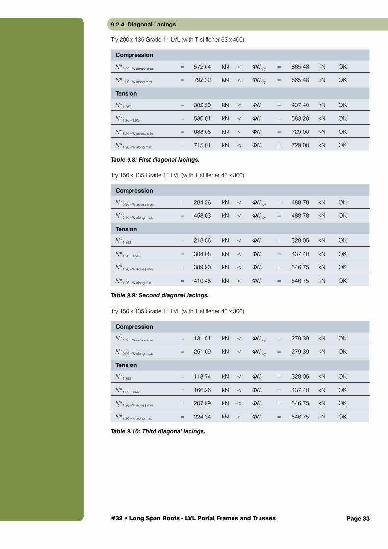
9.2.4 Diagonal Lacings
Try 200 x 135 Grade 11 LVL (with T stiffener 63 x 400) Compression
N*0.9G+W across max. = 572.64 kN < ΦNncy = 865.48 kN OK
N*0.9G+W along max. = 792.32 kN < ΦNncy = 865.48 kN OK
Tension
N*1.35G = 382.90 kN < ΦNt = 437.40 kN OK
N*1.2G+1.5Q = 530.01 kN < ΦNt = 583.20 kN OK
N*1.2G+W across min. = 688.08 kN < ΦNt = 729.00 kN OK
N*1.2G+W along min. = 715.01 kN < ΦNt = 729.00 kN OK
Table 9.8: First diagonal lacings.
Try 150 x 135 Grade 11 LVL (with T stiffener 45 x 360) Compression
N*0.9G+W across max. = 284.26 kN < ΦNncy = 488.78 kN OK
N*0.9G+W along max. = 458.03 kN < ΦNncy = 488.78 kN OK
Tension
N*1.35G = 218.56 kN < ΦNt = 328.05 kN OK
N*1.2G+1.5Q = 304.08 kN < ΦNt = 437.40 kN OK
N*1.2G+W across min. = 389.90 kN < ΦNt = 546.75 kN OK
N*1.2G+W along min. = 410.48 kN < ΦNt = 546.75 kN OK
Table 9.9: Second diagonal lacings.
Try 150 x 135 Grade 11 LVL (with T stiffener 45 x 300) Compression
N*0.9G+W across max. = 131.51 kN < ΦNncy = 279.39 kN OK
N*0.9G+W along max. = 251.69 kN < ΦNncy = 279.39 kN OK
Tension
N*1.35G = 118.74 kN < ΦNt = 328.05 kN OK
N*1.2G+1.5Q = 166.26 kN < ΦNt = 437.40 kN OK
N*1.2G+W across min. = 207.99 kN < ΦNt = 546.75 kN OK
N*1.2G+W along min. = 224.34 kN < ΦNt = 546.75 kN OK
Table 9.10: Third diagonal lacings.
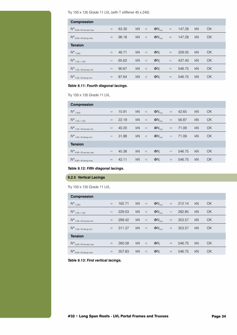
#32 • Long Span Roofs - LVL Portal Frames and Trusses Page 34
Try 150 x 135 Grade 11 LVL (with T stiffener 45 x 240) Compression
N*0.9G+W across max. = 63.30 kN < ΦNncy = 147.28 kN OK
N*0.9G+W along max. = 96.18 kN < ΦNncy = 147.28 kN OK
Tension
N*1.35G = 46.71 kN < ΦNt = 328.05 kN OK
N*1.2G+1.5Q = 65.62 kN < ΦNt = 437.40 kN OK
N*1.2G+W across min. = 90.67 kN < ΦNt = 546.75 kN OK
N*1.2G+W along min. = 87.64 kN < ΦNt = 546.75 kN OK
Table 9.11: Fourth diagonal lacings.
Try 150 x 135 Grade 11 LVL Compression
N*1.35G = 15.91 kN < ΦNncy = 42.65 kN OK
N*1.2G+1.5Q = 22.19 kN < ΦNncy = 56.87 kN OK
N*1.2G+W across min. = 40.20 kN < ΦNncy = 71.09 kN OK
N*1.2G+W along min. = 31.88 kN < ΦNncy = 71.09 kN OK
Tension
N*0.9G+W across max. = 45.36 kN < ΦNt = 546.75 kN OK
N*0.9G+W along max. = 42.11 kN < ΦNt = 546.75 kN OK
Table 9.12: Fifth diagonal lacings.
9.2.5 Vertical Lacings
Try 150 x 135 Grade 11 LVL Compression
N*1.35G = 162.71 kN < ΦNncy = 212.14 kN OK
N*1.2G+1.5Q = 229.03 kN < ΦNncy = 282.85 kN OK
N*1.2G+W across min. = 299.42 kN < ΦNncy = 353.57 kN OK
N*1.2G+W along min. = 311.37 kN < ΦNncy = 353.57 kN OK
Tension
N*0.9G+W across max. = 260.58 kN < ΦNt = 546.75 kN OK
N*0.9G+W along max. = 357.83 kN < ΦNt = 546.75 kN OK
Table 9.13: First vertical lacings.

#32 • Long Span Roofs - LVL Portal Frames and Trusses Page 35
Try 150 x 135 Grade 11 LVL Compression
N*1.35G = 105.58 kN < ΦNncy = 162.38 kN OK
N*1.2G+1.5Q = 149.77 kN < ΦNncy = 216.51 kN OK
N*1.2G+W across min. = 193.77 kN < ΦNncy = 270.64 kN OK
N*1.2G+W along min. = 203.96 kN < ΦNncy = 270.64 kN OK
Tension
N*0.9G+W across max. = 148.53 kN < ΦNt = 546.75 kN OK
N*0.9G+W along max. = 237.15 kN < ΦNt = 546.75 kN OK
Table 9.14: Second vertical lacings.
Try 150 x 135 Grade 11 LVL Compression
N*1.35G = 62.23 kN < ΦNncy = 131.77 kN OK
N*1.2G+1.5Q = 89.22 kN < ΦNncy = 175.69 kN OK
N*1.2G+W across min. = 112.22 kN < ΦNncy = 219.61 kN OK
N*1.2G+W along min. = 121.64 kN < ΦNncy = 219.61 kN OK
Tension
N*0.9G+W across max. = 80.13 kN < ΦNt = 546.75 kN OK
N*0.9G+W along max. = 143.33 kN < ΦNt = 546.75 kN OK
Table 9.15: Third vertical lacings.
Try 150 x 135 Grade 11 LVL Compression
N*1.35G = 24.32 kN < ΦNncy = 106.62 kN OK
N*1.2G+1.5Q = 36.26 kN < ΦNncy = 142.16 kN OK
N*1.2G+W across min. = 51.46 kN < ΦNncy = 177.69 kN OK
N*1.2G+W along min. = 49.64 kN < ΦNncy = 177.69 kN OK
Tension
N*0.9G+W across max. = 40.23 kN < ΦNt = 546.75 kN OK
N*0.9G+W along max. = 61.27 kN < ΦNt = 546.75 kN OK
Table 9.16: Fourth vertical lacings.

#32 • Long Span Roofs - LVL Portal Frames and Trusses Page 36
Try 150 x 135 Grade 11 LVL Compression
N*0.9G+W across max. = 30.20 kN < ΦNncy = 144.89 kN OK
N*0.9G+W along max. = 51.69 kN < ΦNncy = 144.89 kN OK
Tension
N*1.35G = 25.04 kN < ΦNt = 328.05 kN OK
N*1.2G+1.5Q = 32.70 kN < ΦNt = 437.40 kN OK
N*1.2G+W across min. = 40.80 kN < ΦNt = 546.75 kN OK
N*1.2G+W along min. = 45.28 kN < ΦNt = 546.75 kN OK
Table 9.17: Fifth vertical lacings.

#32 • Long Span Roofs - LVL Portal Frames and Trusses Page 37
References
Australian Standards
AS 1170.0 Structural design actions, General principles. 2002, Standards Australia, Australia
AS 1170.1 Structural design actions, Permanent, imposed and other actions. 2002, Standards Australia, Australia
AS 1170.2 Structural Design Actions, Part 2: Wind Actions. 2002, Standards Australia, Australia
AS 1720.1 Timber structures, Part 1: Design methods. 2010, Standards Australia, Australia
WoodSolutions Technical Design Guides
WoodSolutions Technical Design Guide #33: Quick Connect Moment Connection, Forest and Wood Products Australia, 2015, Melbourne, Australia.
WoodSolutions Technical Report
WoodSolutions Technical Report: Timber Portal Frames, Forest and Wood Products Australia, 2015, Melbourne, Australia.

#32 • Long Span Roofs - LVL Portal Frames and Trusses Page 38
The symbols and letters used in the Guide are listed below:
A cross-sectional area
bf width of box-beam
Cdyn dynamic response factor, as given in Section 6 of AS 1170.2
Cfig aerodynamic shape factor, as given in Section 5 of AS 1170.2
d depth of member
E modulus of elasticity of member
h column height
ht,eave eave height
ht,apex apex height
I cross-sectional area
L span of the structure
M* design action moment
Mn design moment capacity
N* design compression force
n n value used in the calculation of wind pressure
P design wind pressure in Pascals
tf flange thickness
tw web thickness
V nominal shear strength
Vdes,θ building orthogonal design wind speeds given in Clause 2.3 AS 1170.2
θ roof pitch of the building
Φ capacity factor
ρair density of air, which shall be taken as 1.2 kg/m3
AAppendix A – Notation

Discover more ways to build your knowledge of wood If you need technical information or inspiration on designing and building with wood, you’ll find WoodSolutions has the answers. From technical design and engineering advice to inspiring projects and CPD linked activities, WoodSolutions has a wide range of resources and professional seminars.
www.woodsolutions.com.auYour central resource for news about all WoodSolutions activities and access to more than three thousand pages of online information and downloadable publications.
Technical PublicationsA suite of informative, technical and training guides and handbooks that support the use of wood in residential and commercial buildings.
WoodSolutions TutorialsA range of practical and inspirational topics to educate and inform design and construction professionals. These free, CPD related, presentations can be delivered at your workplace at a time that suits you.
Seminars and EventsFrom one day seminars featuring presentations from leading international and Australian speakers to international tours of landmark wood projects, WoodSolutions offer a range of professional development activities.
What is WoodSolutions?Developed by the Australian forest and wood products industry for design and building professionals, WoodSolutions is a non-proprietary source of information from industry bodies, manufacturers and suppliers.