Long Life Copper Stave for Blast Furnace Developed by ... · Long Life Copper Stave for Blast...
14
Technical Report 1 Long Life Copper Stave for Blast Furnace Developed by Nippon Steel & Sumikin Engineering ~Advanced Technologies of Cast-in steel Pipe Copper Stave~ Makoto GOTO Plant & Machinery Division Steel Plant Engineering Department – I Iron Making - Engineering & Development Abstract Stave is the equipment for maintaining the furnace inside profile and protecting the furnace shell from the high temperature gas or molten material. Among them, copper stave is installed to lower part of blast furnace in a high heat region. The water channel of conventional copper stave is made by drilling to the copper plate. On the other hand, we developed cast-in steel pipe copper stave whose water channel is made by casting the bended steel pipe to the copper. The functions required for stave is classified in 3 points; ① Long life and high reliability,②Appropriate cooling performance and ③Heat insulation performance. Cast-in steel pipe copper stave has more excellent performance in these 3 functions than conventional one. In this paper, the advantages in technology of cast-in steel pipe copper stave are described. Key word : Life-cycle cost reduction, Long life copper stave, Stave cooler, Blast furnace
Transcript of Long Life Copper Stave for Blast Furnace Developed by ... · Long Life Copper Stave for Blast...

Technical Report
1
Long Life Copper Stave for Blast Furnace Developed by Nippon Steel &
Sumikin Engineering
~Advanced Technologies of Cast-in steel Pipe Copper Stave~
Makoto GOTO
Plant & Machinery Division
Steel Plant Engineering Department – I
Iron Making - Engineering & Development
Abstract
Stave is the equipment for maintaining the furnace inside profile and protecting the furnace shell from the
high temperature gas or molten material. Among them, copper stave is installed to lower part of blast
furnace in a high heat region. The water channel of conventional copper stave is made by drilling to the
copper plate. On the other hand, we developed cast-in steel pipe copper stave whose water channel is made
by casting the bended steel pipe to the copper. The functions required for stave is classified in 3 points; ①
Long life and high reliability,②Appropriate cooling performance and ③Heat insulation performance.
Cast-in steel pipe copper stave has more excellent performance in these 3 functions than conventional one.
In this paper, the advantages in technology of cast-in steel pipe copper stave are described.
Key word : Life-cycle cost reduction, Long life copper stave, Stave cooler, Blast furnace
Long Life Copper Stave for Blast Furnace Developed by Nippon Steel & Sumikin Engineering
~Advanced Technologies of Cast-in steel Pipe Copper Stave~
NIPPON STEEL & SUMIKIN ENGINEERING CO., LTD. TECHNICAL REVIEW vol. 8 (2017) 2
1 Introduction
Amid the growing international concerns for
global warming, the demand for reducing
greenhouse gas emissions, particularly the
emission of CO2, is increasing. CO2 emissions
from the steel industry are very high at 15% of
the world’s total CO2 emission, 70% or more of
which is from the pig iron making process. Since
a major part of CO2 emissions depends on the
energy efficiency of the equipment, the steel
industry is required to use blast furnaces with
higher energy efficiency.
Nippon Steel & Sumikin Engineering have
constructed and revamped more than 70 blast
furnaces over the past 50 years. In each project,
starting from the study of operational
specifications, we handled the design,
manufacture, and construction of the entire blast
furnace equipment. Based on the experience
obtained from working with such a wide range of
processes, we have developed various types of
energy-saving equipment.
Blast furnaces provided by us and used in Japan’s
steel industry, which is one of the most advanced
steel industries in introducing energy-saving
equipment, have achieved the world’s lowest
energy consumption for the manufacture of a ton
of crude steel.
Since a blast furnace is situated in the upstream in
a steel plant, and it also operates throughout the
year, those with longer life and higher reliability
are desired. In this respect, we are using our
wide-ranging expertise fostered through the
extensive experience for the development and
design of the equipment life extension.
This paper describes the cast-in steel pipe copper
stave that is one of the long-life, energy-saving
equipment we have developed.
2 What Is a Copper Stave?
The Plant Machinery Division at Nippon Steel
Corporation (which later became Nippon Steel &
Sumikin Engineering) incorporated the
technology of cast iron staves from the Soviet
Union in 1969 for the first time. Since then, we
have repeatedly improved the technology based
on the results of the use under actual operation.
As a result, we have succeeded in extending the
average furnace life from 5 to 7 years to 15 to 16
years. We have delivered this cast iron stave to
about 180 blast furnaces both in Japan and
overseas, and contributed to the furnace life
extension.
However, even longer furnace life, over 20 years,
is now desired. The cast iron stave, due to its
material characteristics, causes material
deterioration at the lower part of the blast furnace,
which is exposed to high heat load. This has
made it difficult to achieve stable furnace life of
20 years using the cast iron stave. As an
alternative cooling means to the cast iron stave
considering the high heat load, the rolled copper
stave was developed. This type of stave is made
from a rolled copper plate on which holes are
drilled and water supply and drain pipes are
welded to form water channels. The use of rolled
copper staves was started in Germany in the mid-
1990s, and has been spread to blast furnaces in
many countries.

Technical Report
3
Other copper staves developed to date include
cast copper staves with water channels formed
using a core in the casting process, and cast-in
monel pipe copper staves with water channels
formed using monel pipes bent into a channel
shape and cast.
However, these copper staves had the problems as
described below. To solve the problems, we made
the best use of our manufacturing and design
expertise regarding cast-iron staves accumulated
over 40 years to develop the cast-in steel pipe
copper stave, which has been used in actual blast
furnaces since 2004.
3 What is a Cast-In Steel Pipe Copper
Stave?
Currently, the most popular type of copper stave
is the rolled copper stave, the manufacturing
process of which involves drilling holes on a
copper plate as described above. The water
channel ends of this stave are plug-welded.
The cast-in steel pipe copper stave developed by
us is made by casting bent steel pipes into the
copper, a completely different manufacturing
process from that of the conventional rolled
copper stave. This unique manufacturing method
has enabled achieving high energy efficiency and
long life of blast furnaces, which cannot be
achieved using the rolled copper stave.
4 Properties Required for a Stave
To reduce and melt iron ore, high-temperature gas
around 1,200°C is blown into a blast furnace. A
stave is a cooling facility installed on the inner
surface of the shell to protect the shell from the
high-temperature gas and molten burden material
in the furnace, maintaining the profile inside the
furnace. The following three properties are
mainly required for a stave.
(1) Long life and reliability
Since it is impossible to repair a stave from
outside the blast furnace due to its structure,
extensive replacement work is required when the
stave is damaged. Damaged staves have serious
adverse effects on plant operations, causing a
long blowing-stop, the temperature drop inside
the furnace due to water leakage, or changing the
profile which may result in operational failure.
For this reason, stable long life is required for
staves.
(2) Appropriate cooling ability
To protect the shell from high-temperature gas
around 1,200°C and molten material, appropriate
cooling ability is required for staves. Since high
cooling ability is required for cooling the furnace
part between the bosh and lower part of the shaft,
which is exposed to high temperature, a copper
stave is used for this part in many cases.
(3) Thermal insulation ability
A blast furnace in which iron oxide is reduced
and melted at high temperature is desired to have
a heat insulation structure not to waste thermal
energy. On the other hand, as described above, a
stave is cooled to maintain the profile inside the
blast furnace and to protect the shell. Therefore, it
removes thermal energy from the high-
temperature gas and material. Removing heat by

Long Life Copper Stave for Blast Furnace Developed by Nippon Steel & Sumikin Engineering
~Advanced Technologies of Cast-in steel Pipe Copper Stave~
NIPPON STEEL & SUMIKIN ENGINEERING CO., LTD. TECHNICAL REVIEW vol. 8 (2017) 4
a stave involves the equivalent fuel (coke)
consumption, directly causing an increase in the
reducing agent rate (RAR). An increase in the
RAR may in turn lead to an increase in CO2
emissions and rise of the unit price of molten pig
iron. For this reason, a stave must have
appropriate heat insulation (heat removal
restriction) ability to minimize heat energy taken
from inside the furnace, as well as appropriate
cooling ability.
Conventionally, bricks with low thermal
conductivity are embedded at the front of a cast
iron stave to obtain both cooling ability and heat
insulation ability.
Meanwhile, a copper stave is used to form a heat
insulation layer from semi-molten material
located in front of the stave by cooling such
material with the high cooling ability to make it
adhere to the inner surface of the stave.
In the following chapter, we discuss the
differences and advantages of the cast-in steel
pipe copper stave compared with the rolled
copper stave regarding these properties.
5 Technical Advantages of the Cast-In Steel
Pipe Copper Stave
5.1 Long life and reliability
Rolled copper staves sometimes have the
following three problems.
(1) Deformation
Rolled copper staves are warped due to the
difference in thermal expansion between the stave
inner surface, which is exposed to high
temperature gas, and the stave outer surface,
which is cooled. They are seriously deformed
when a stave is too long or when the positions of
fixing bolts are not appropriate.
Such deformation may cause a wear of a
protruding portion and breakage of a weld due to
high temperature gas flowing to stave joints and
back surfaces.
(2) Weld cracking due to thermal fatigue
Welds of rolled copper staves are subjected to
repeated thermal stresses due to the temperature
fluctuation, resulting in cracking and breakage.
(3) Wear
Iron ore, sintered steel, and coke, have higher
hardness than that of copper, abrade copper staves
when they contact the stave surface and descend.
In general, the wear rate of a copper stave
depends on the contact force and descending
speed of the material in contact with the stave
surface, hardness of the copper and material, and
the shape of the material.
To solve these problems, we started the
development of a new copper stave that has three
advantages.
5.1.1 Deformation resistance
For the prevention of deformation, appropriate
design of the stave length and bolt constrained
points is important. The use of the cast-in steel
pipe copper stave with its own design is
beneficial for effectively reducing the risk of
deformation.

Technical Report
5
Figure 1 shows the constrained points of a rolled
copper stave and the cast-in steel pipe copper
stave.
(1) Rolled copper stave
A rolled copper stave is constrained to the shell
by mounting bolts and pins. To prevent the weld
at the base of a rising pipe from being damaged
by stresses, rising piping is connected to the shell
by an expansion joint. Due to this structure, the
upper and lower ends of the stave are freely
displaced, causing the stave to be easily
deformed. The large thermal load that is
repeatedly applied to the copper stave in the
course of the fluctuation in blast furnace
operations, etc., causes plastic strain to be
gradually accumulated, and results in large
deformation. There are cases in which the
deformation at the upper end reached 50 mm or
more and a weld was broken, under the condition
of an overly long stave, an inappropriate bolt
position, or high heat load exceeding the design
condition.
(2) Cast-in steel pipe copper stave
The cast-in steel pipe copper stave has the
following three deformation-resistant features.
1) Constraint of protective pipe
As shown in Fig. 1, for the cast-in steel pipe
copper stave, gas seal boxes in addition to bolts
are used to fix the protective pipes at the ends of
the stave. This applies the displacement constraint
to the upper and lower ends of the stave.
Furthermore, as shown in Fig. 2, since the
protective pipe is casted in the body of the copper
stave, no welds with a breakage risk are used.
Fig. 1: Difference of positions of constrained
points
Fig. 2: Structure of protective pipe
2) Frame structure with cast-in pipes
As shown in Fig. 1, the cast-in steel pipe copper
stave uses steel pipes, which are stiffer than
copper and serve as the framework. The use of
steel pipes provides a structure that is more
deformation-resistant than conventional copper
staves.

Long Life Copper Stave for Blast Furnace Developed by Nippon Steel & Sumikin Engineering
~Advanced Technologies of Cast-in steel Pipe Copper Stave~
NIPPON STEEL & SUMIKIN ENGINEERING CO., LTD. TECHNICAL REVIEW vol. 8 (2017) 6
3) Cooling and stress mitigation using a
bumpy stave inner surface
The inner surface of the cast-in steel pipe copper
stave is made bumpy. Figure 3 shows the cross-
sectional shapes of a rolled copper stave and the
cast-in steel pipe copper stave. Since rolled
copper staves have a rectangular cross-sectional
shape, the temperature increases at locations on
the stave inner surface far from water channels. In
contrast, the cast-in steel pipe copper stave uses a
bumpy surface to render the distance between the
stave inner surface and each water channel
virtually constant around the water channel. This
allows the stave inner surface to be uniformly
cooled. Such uniform cooling in turn reduces the
temperature difference between the stave inner
and outer surfaces, and suppresses thermal
stresses and deformation.
Fig. 3: Uniform cooling by bumpy shape
Furthermore, as shown in Fig. 4, under large
thermal load, compression plastic strain is caused
on the stave inner surface of a rolled copper stave
by the temperature difference between the stave
inner and outer surfaces, which may lead to stave
deformation. In contrast, the inner surface of the
cast-in steel pipe copper stave is isolated at each
bump, thereby making compression stresses less
likely to act on the stave and suppressing plastic
strain.
Fig.4: Stress reduction by bumpy shape
As described above, the bumpy surface of the
cast-in steel pipe copper stave reduces stresses
and strains that act on the stave, and suppresses
deformation.
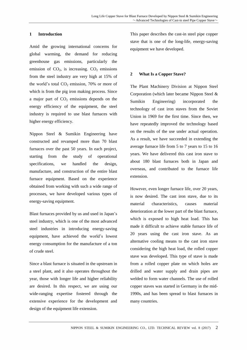
According to the analysis results of thermal stress
on the cast-in steel pipe copper stave under large
thermal load as shown in Fig. 5, the warped
amount is approx. 1.2 mm. This level of
Technical Report
7
protrusion of the stave is considered sufficiently
small to prevent any problems.
Fig. 5: Deformation quantity
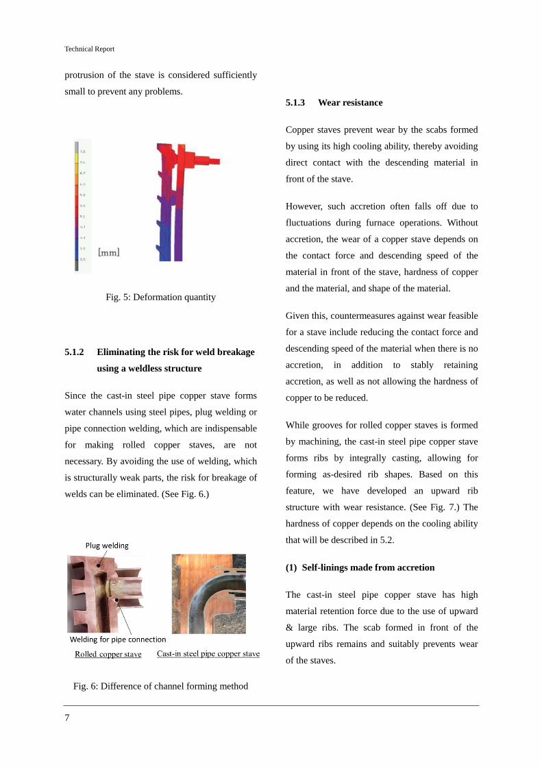
5.1.2 Eliminating the risk for weld breakage
using a weldless structure
Since the cast-in steel pipe copper stave forms
water channels using steel pipes, plug welding or
pipe connection welding, which are indispensable
for making rolled copper staves, are not
necessary. By avoiding the use of welding, which
is structurally weak parts, the risk for breakage of
welds can be eliminated. (See Fig. 6.)
Fig. 6: Difference of channel forming method
5.1.3 Wear resistance
Copper staves prevent wear by the scabs formed
by using its high cooling ability, thereby avoiding
direct contact with the descending material in
front of the stave.
However, such accretion often falls off due to
fluctuations during furnace operations. Without
accretion, the wear of a copper stave depends on
the contact force and descending speed of the
material in front of the stave, hardness of copper
and the material, and shape of the material.
Given this, countermeasures against wear feasible
for a stave include reducing the contact force and
descending speed of the material when there is no
accretion, in addition to stably retaining
accretion, as well as not allowing the hardness of
copper to be reduced.
While grooves for rolled copper staves is formed
by machining, the cast-in steel pipe copper stave
forms ribs by integrally casting, allowing for
forming as-desired rib shapes. Based on this
feature, we have developed an upward rib
structure with wear resistance. (See Fig. 7.) The
hardness of copper depends on the cooling ability
that will be described in 5.2.
(1) Self-linings made from accretion
The cast-in steel pipe copper stave has high
material retention force due to the use of upward
& large ribs. The scab formed in front of the
upward ribs remains and suitably prevents wear
of the staves.

Long Life Copper Stave for Blast Furnace Developed by Nippon Steel & Sumikin Engineering
~Advanced Technologies of Cast-in steel Pipe Copper Stave~
NIPPON STEEL & SUMIKIN ENGINEERING CO., LTD. TECHNICAL REVIEW vol. 8 (2017) 8
(2) Reduction of the contact force and
descending speed of material
If there is no accretion inside-furnace surface of a
rolled copper stave, material once entered
between ribs hardly moves because the ribs are
small. Therefore, material in front of the stave
descends without being influenced by the ribs. In
contrast, since the ribs of the cast-in steel pipe
copper stave face upward and are large, material
that has entered between the ribs is discharged
back into the furnace, creating a flow (load
transfer). At this time, the material is discharged
upward. This upward flow pushes the material in
front of the stave back to the furnace, causing the
contact force and descending speed of the
material to be reduced at the rib tips.
Fig. 7: Upward ribs (Cross section)
Figure 8 shows the results of a DEM (discrete
element method) analysis in which material is
modeled using particles to simulate the material
descending behavior.
Fig. 8: Simulation for burden descending
behavior by DEM analysis
Figure 8 shows that a stagnation layer consists of
slowly descending material formed on the stave
surface due to the effect of the upward ribs
described above. According to the results of the
DEM analysis, the contact force acting on the rib
tips was reduced by approx. 40%, and the
descending speed of the material was reduced by
60 to 70%.
Assuming that the wearing rate is in proportion to
the product obtained by multiplying the contact
force by descending speed, reductions in the
contact force and descending speed cause the
wearing rate to be approx. 0.25 times. Thus, the
stave life is expected to extend nearly 4 times.
For new blast furnaces, we have achieved a
longer copper stave life by designing the
optimum profile in the furnace and stave rib
shape. For existing blast furnaces with copper
staves rapidly worn by contact force and
descending speed increased due to an inadequate
profile, or worn by material with increased
descending speed during operations at the high
pig iron tapping ratio, both the contact force and
descending speed of the material can be reduced
by replacing existing rolled copper staves with
our staves. If the life of an existing stave is 5–6

Technical Report
9
years, it can be extended 4 times to approx. 20
years.
5.2 Appropriate cooling ability
To prevent a stave shell from being damaged and
also prevent a copper stave from deformation and
wearing due to a decrease in the copper hardness,
it is required to maintain the appropriate cooling
ability throughout the furnace life. Although
regarding the cast-in steel pipe copper stave there
are concerns about insufficient cooling ability due
to steel pipes with low heat conductivity located
on thermal conductive pathways and about the
separation of steel pipes from copper impairing
the cooling ability, these problems have already
been solved by the following technologies.
(1) Cooling ability
Table 1 shows the purity and thermal conductivity
of the copper used for rolled copper staves, cast
copper staves, and the cast-in steel pipe copper
stave. Although the cast-in steel pipe copper stave
has low cooling ability when compared with
rolled copper staves made of high-purity copper
only, the cooling ability of the cast-in steel pipe
copper stave, which uses 99.9% high-purity
copper, supersedes that of cast copper staves with
a proven track record.
Table 1: Thermal conductivity for each copper
staves
Type of copper
Stave Material
Purity of
Copper
Thermal Conductivity
[kcal/m-h-°C]
Rolled & Drilled
Type
Rolled
copper ≥ 99.9% 315
Cast Type
Cast Copper
(CAC101)
≥ 99.5% 173
Cast-in
Steel
Pipe Type
Copper
Cast
Copper
(CAC103)
≥ 99.9% 260
Pipe Steel Pipe — 40
Figure 9 shows the results of 3D thermal
conductivity analysis for each copper stave. The
surface temperature of the cast-in steel pipe
copper stave inside the furnace is lower than that
of cast copper staves with a proven track record,
thus indicating impeccable cooling ability.
Fig. 9: Results of 3D thermal conductivity
analysis
(2) Adhesion between copper and steel pipes
To maintain the cooling ability of the cast-in steel
pipe copper stave, joint surfaces of the copper
base metal and a steel pipe adhering to each other
are required to not separate, withstanding
repeated stresses from thermal fluctuation inside

Long Life Copper Stave for Blast Furnace Developed by Nippon Steel & Sumikin Engineering
~Advanced Technologies of Cast-in steel Pipe Copper Stave~
NIPPON STEEL & SUMIKIN ENGINEERING CO., LTD. TECHNICAL REVIEW vol. 8 (2017) 10
the furnace. If the joint surfaces are separated, the
heat transfer ability of the stave between the
copper base metal and steel pipe is impaired,
increasing the risk of base metal temperature rise
resulting in problems. For removing such a risk,
we have developed unique manufacturing
technologies to obtain high adhesion between the
copper and steel pipes.
Various examinations as described below were
conducted through which the adhesion between
the copper and steel pipes was verified, and the
reliability was checked.
i) Metal structure observation by EPMA
Fig. 10: Observation of metal structure by EPMA
Figure 10 shows the results of metal structure
observation using an EPMA (electron probe
micro analyzer) at the boundary between the
copper and a steel pipe. The left side in the two
images shows the Fe distribution, and the right
side shows the Cu distribution. At the joint, Fe
and Cu mutually diffuse, showing that a strong
joint surface is formed.
ii) Tensile test and shear strength test
To evaluate the mechanical adhesive strength
between the copper and steel pipes, we conducted
a tensile test and shear strength test under a high
temperature at 400°C. Figure 11 shows the result
of the tensile test. Figure 13 shows the result of
the shear strength test. During both tests, while no
fracture occurred on the surface on which copper
and steel adhere to each other, the copper side
fractured. Thus, the part at which copper and steel
adhere to each other has sufficient strength
exceeding the mechanical strength of the copper
base metal.
Fig. 11: Tensile strength test of adhesion part
Fig. 12: Shear strength test of adhesion part
iii) Heat shock test
To confirm the adhesion and thermal conductivity
between the copper and steel pipes after
undergoing repeated thermal load, we conducted
a heat shock test as shown in Fig. 13. For the
examination, we applied heat shocks to the
specimen by heating the top surface of the
specimen using a burner until the temperature in
the position approx. 10 mm above the steel pipe
was elevated to 400°C, and then cooled the
specimen by running cooling water through the

Technical Report
11
pipe (Fig. 14). This process was repeated 20
times. Since the surface temperature of copper
staves 50 mm or more away from the pipe is
usually controlled to not exceed the level of 200–
250°C, the thermal load in this test was more
severe than during actual furnace operations.
Fig. 13: Examination of heat shock
Fig. 14: Condition of heat load
As a result, after sustained repeated heat shocks
of the specimen, neither the separation of the pipe
from the base metal at the joint surface nor
deterioration of thermal conductivity was
observed. In view of the result of this
examination, no separation at the joint surface or
reduction of the thermal conductivity is expected
under the conditions of the furnace operations.
As discussed above, there is no concern such as
insufficient cooling ability or separation of the
steel pipes from the copper in the practical use of
the cast-in steel pipe copper stave.
5.3 Thermal insulation ability
The upward ribs of the cast-in steel pipe copper
stave allow for stable formation of a self-lining
layer that prevents the stave from wearing and
serves as a heat insulation layer on the inner
surface.
Figure 15 graphically illustrates the temperature
measured for a week at the rib tip of a rolled
copper stave and the cast-in steel pipe copper
stave those are installed at the shaft level.
Fig. 15: Temperature data of copper stave
Comparing the two staves, we can see that the
cast-in steel pipe copper stave has smaller
temperature fluctuation than that of the rolled
copper stave. It appears that this is caused by a
stable accretion or stagnation layer thanks to the
upward ribs. This can be seen from the DEM
analysis results shown in Fig. 8. Since the
accretion and stagnation layer have lower heat
conductivity than that of copper, they work as a
thermal insulation layer.
Figure 16 shows the results of heat conductivity
analysis when the stave inner surface is heated for
each rolled copper stave and cast-in steel pipe
copper stave assuming that material is adhered
between the ribs of both staves. Comparing the
two staves, the average temperature of the cast-in

Long Life Copper Stave for Blast Furnace Developed by Nippon Steel & Sumikin Engineering
~Advanced Technologies of Cast-in steel Pipe Copper Stave~
NIPPON STEEL & SUMIKIN ENGINEERING CO., LTD. TECHNICAL REVIEW vol. 8 (2017) 12
steel pipe copper stave’s inner surface was higher
by approx. 70°C than that of the rolled copper
stave. Possible causes of this difference are
considered below.
• Larger pitch of the ribs
Copper has high thermal conductivity and low
temperature is maintained at the rib tips. Since the
cast-in steel pipe copper stave has large pitch of
the ribs, it can reduce the area of each rib tip that
is in contact with gas in the furnace.
Fig. 16: Results of 3D thermal conductivity
analysis
• Deeper ribs
The cast-in steel pipe copper stave, as shown in
Fig. 7, is enabled to have deeper ribs than those
of rolled copper staves by the bumpy inner
surface. This allows the material adhering to the
stave between the ribs to be thick.
Since the heat transfer coefficient is determined
by dividing the thermal conductivity by thickness,
the thicker the accretion is, the lower the heat
transfer coefficient becomes and the higher the
surface temperature of the adhering material
becomes as well. Therefore, the average
temperature on the surface of the accretion inside
the furnace of the cast-in steel pipe copper stave
is higher than that of rolled copper stave.
Fig. 17: Difference of the extraction of heat
As the surface temperature becomes high, the
temperature difference between the working
surface and gas inside the furnace becomes
smaller. This reduces the removed amount of
heat. The amount of heat removed by the gas
inside the furnace can be expressed using the
following equation.
q=Q/A=h×ΔT
From a calculation using the equation, the
difference of removed heat caused by the
temperature difference by 70°C is approx. 0.02
MW/m2.
By suppressing heat removal from the furnace,
the consumption of coke equivalent to the
removed amount of heat can be reduced as well.
In the case of a 5,000 m3-class blast furnace for
instance, this means a coke consumption
reduction of nearly 14,000 tons per year.

Technical Report
13
6 Other Characteristics of the Cast-In Steel
Pipe Copper Stave
In addition to the technical advantages in
extending life and saving energy, the cast-in steel
pipe copper stave has also the characteristic of the
high design flexibility.
When a cast iron stave or cooling plate that a
blast furnace uses is broken and something needs
to be done in order to extend the life, the
replacement with a copper stave using the
existing shell opening may be required.
In the case of rolled copper staves, since water
channels are formed by drilling, the water
channel layout is restricted, making it difficult to
freely form water channels in a manner tailored to
the existing shell opening. In contrast, water
channels of the cast-in steel pipe copper stave,
which are formed using bent steel pipes, allow for
flexible layout adopting steel pipes for the
existing opening of the shell (Fig. 19).
Fig. 18: Shell openings for cast iron stave and
cooling plate
Fig. 19: High flexibility of cooling channel layout
7 Track Record of Use at Actual Plants
Multiple furnaces in operation have already
adopted the cast-in steel pipe copper stave, and
these furnaces have been stably operated since.
One of those is a SSAB Raahe steel (former
name: Rautaruukki) blast furnace No. 2, to which
the cast-in steel pipe copper stave with the
upward ribs had been set in the part between the
bosh and lower stack as shown in Fig. 20.
In the case of Raahe blast furnace No. 2, the
maximum amount of wear on the copper stave
surface was 0.3 mm/year. This indicates that the
stave life likely be more than 20 years.
Fig. 20: Raahe No. 2BF

Long Life Copper Stave for Blast Furnace Developed by Nippon Steel & Sumikin Engineering
~Advanced Technologies of Cast-in steel Pipe Copper Stave~
NIPPON STEEL & SUMIKIN ENGINEERING CO., LTD. TECHNICAL REVIEW vol. 8 (2017) 14
8 Conclusion
The cast-in steel pipe copper stave has the
following technical advantages over rolled copper
staves.
(1) Longer life
The main problems of copper staves are (1)
deformation; (2) damage of welds; and (3) wear.
For the cast-in steel pipe copper stave, unique
countermeasures against these issues have been
taken, greatly reducing or even eliminating the
risks of the problems.
(2) Appropriate cooling ability
The unique manufacturing method we developed
has allowed for strong adhesion of steel pipes to
copper, enabling the stave to have sufficient
cooling ability that can be sustained throughout
the furnace life.
(3) Thermal insulation ability
The upward ribs of the cast-in steel pipe copper
stave allow burden material to stably adhere to
the stave surface between these ribs. Since this
accretion has low heat conductivity and works as
a thermal insulation layer, the amount of heat
removed from the furnace is smaller by about
0.02 MW/m2 than that in the case of a rolled
copper stave. Such energy-saving effect from the
heat removal restriction is equivalent to the coke
consumption reduction of nearly 14,000 tons per
year for a 5,000 m3-class blast furnace.
(4) Increased design flexibility
Casting steel pipes into a copper stave has
increased the flexible design of water channels. A
cast iron stave and cooling plate can be easily
replaced with a copper stave using cast steel
pipes.
The cast-in steel pipe copper stave of Nippon
Steel & Sumikin Engineering can thus contribute
to life extension and energy efficiency
improvement of blast furnaces.