London Gateway Logistics Park Local Development Order
84
Design Code London Gateway Logistics Park Local Development Order October 2013
Transcript of London Gateway Logistics Park Local Development Order

Design Code
London Gateway Logistics ParkLocal Development Order
October 2013

London Gateway Logistics Park Design Code
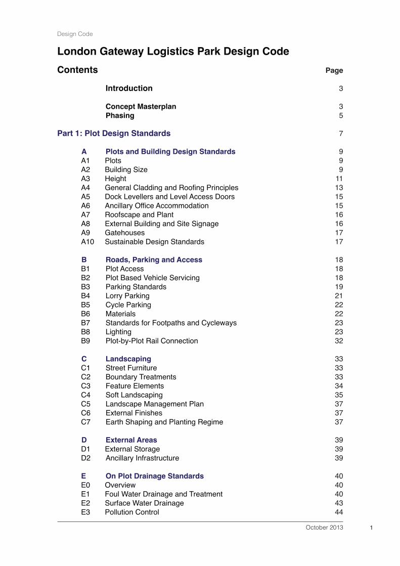
Contents
Introduction
Concept MasterplanPhasing
Part 1: Plot Design Standards
A Plots and Building Design StandardsA1 PlotsA2 Building SizeA3 HeightA4 General Cladding and Roofing PrinciplesA5 Dock Levellers and Level Access DoorsA6 Ancillary Office AccommodationA7 Roofscape and Plant A8 External Building and Site SignageA9 GatehousesA10 Sustainable Design Standards
B Roads, Parking and AccessB1 Plot AccessB2 Plot Based Vehicle ServicingB3 Parking StandardsB4 Lorry ParkingB5 Cycle ParkingB6 MaterialsB7 Standards for Footpaths and CyclewaysB8 LightingB9 Plot-by-Plot Rail Connection
C LandscapingC1 Street FurnitureC2 Boundary TreatmentsC3 Feature ElementsC4 Soft LandscapingC5 Landscape Management PlanC6 External FinishesC7 Earth Shaping and Planting Regime
D External AreasD1 External StorageD2 Ancillary Infrastructure
E On Plot Drainage StandardsE0 OverviewE1 Foul Water Drainage and TreatmentE2 Surface Water DrainageE3 Pollution Control
October 2013 1
Design Code
Page
3
35
7
999
1113151516161717
18181819212222232332
3333333435373737
393939
4040404344
PART 2: Infrastructure Standards
F Highway Design StandardsF1 Internal Access RoadsF2 Road DrainageF3 Pollution ControlF4 MaterialsF5 Bus Routes and FacilitiesF6 Soft LandscapingF7 Lighting Requirements F8 SignageF9 Emergency Access
G Park Drainage StandardsG1 Surface Water DrainageG2 SwalesG3 Carterʼs Bay LagoonG4 The Pumping Station and Outfall ArrangementG5 Pollution ControlG6 Operation and Maintenance
H Land RaisingH1 Land Raising
I General Landscaping RequirementsI1 Soft Landscape SpecificationI2 Strategic Landscaping FrameworkI3 Street Furniture, Boundary Treatments & Feature ElementsI4 Landscape Management Plan
J Services InfrastructureJ1 Gas Supply J2 Potable and Non Potable Water Supply J3 Electricity SupplyJ4 TelecommunicationsJ5 Fire Fighting SystemsJ6 Utility InfrastructureJ7 Sub Stations, Pumping Houses and Other Non-commercial
Buildings.
Appendices
Appendix 1: Soft Landscaping SpecificationAppendix 2: Landscape Management PlanAppendix 3: Structural Landscape Plans (North)Appendix 4: Structural Landscape Plan (West) Appendix 5: Terms of Reference for London Gateway Services Ltd
October 20132
Design Code
Page
47
49494949525254545657
58585859606363
6565
6666666669
707070707070 7171

Introduction
1. The London Gateway Logistics Park Design Code forms part of the LondonGateway Logistics Park Local Development Order (LDO) and must be read inconjunction with it.
2. The Design Code sets out the minimum standards to be applied to the buildingplots, infrastructure and amenity space on site. Its purpose is to ensure that ahigh and consistent standard of design is maintained throughout the logistics parkto provide a sustainable and stimulating working environment whilst at the sametime enabling the diverse requirements of individual occupiers to be met.
3. Development must accord with all aspects of the Design Code in order to benefitfrom the permitted development rights conferred by the LDO.
Concept Masterplan
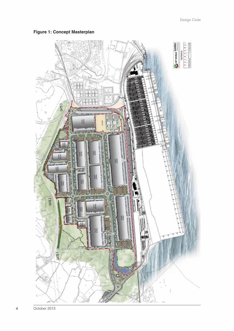
4. The concept masterplan (see Figure 1) shows an indicative arrangement of routesand spaces that shall provide structure to the logistics park. Strategically locatedprimary infrastructure corridors shall allow a plot-by-plot development of the site.The concept masterplan is intended as a guide only. The layout shall be flexibleand responsive to existing and future commercial requirements. The release ofplots and associated infrastructure requirements shall be in response tocommercial need.
5. Development along the northern boundary shall be characterised by smaller plotsof varying depth and buildings restricted in height to no more than 16m to providea graduation in scale between surrounding areas and the core of the site wherelarger distribution and industrial buildings up to 42m are to be located. Plots alongthe southern edge of the Park have the potential to be directly linked to thenational rail network and this potential shall be safeguarded as plots aredeveloped.
6. Infrastructure corridors shall accommodate roadways, cycleways and footpaths,and provide service zones for utilities and treated foul and surface water drainage.The positioning of the primary infrastructure will inform the precise location andmaximum size of the building plots within the development.
7. The Park shall be accessed via the new London Gateway Access Road to thewest of the Site once it is operational. This access road shall also serve theLondon Gateway Port. Gates 1 and 3 shall provide emergency access to theManorway for emergency vehicles and buses.
8. Amenity spaces shall be linked by an infrastructure network to create anenvironment that will, over the lifetime of the development, provide an attractivelocation for prospective investors and occupiers.
October 2013 3
Design Code
October 20134
Design Code
Figure 1: Concept Masterplan
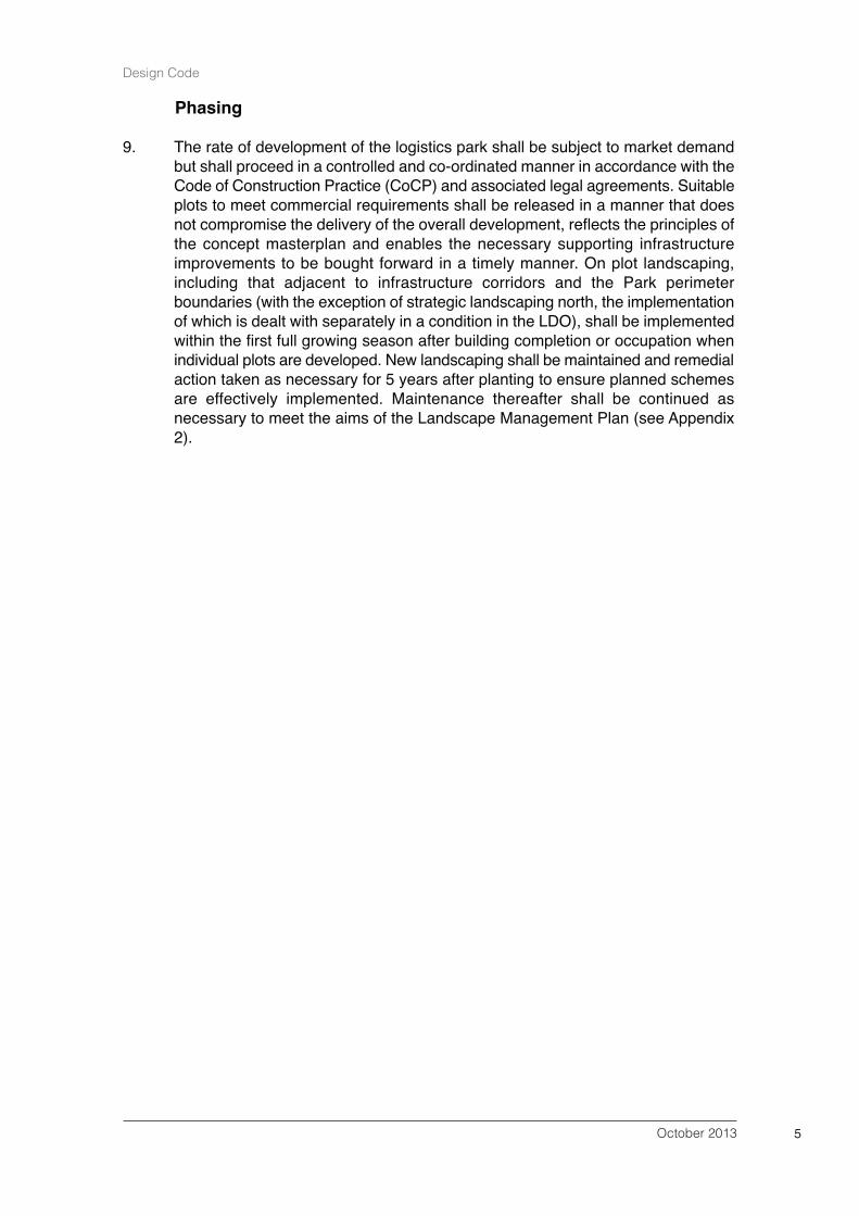
Phasing
9. The rate of development of the logistics park shall be subject to market demandbut shall proceed in a controlled and co-ordinated manner in accordance with theCode of Construction Practice (CoCP) and associated legal agreements. Suitableplots to meet commercial requirements shall be released in a manner that doesnot compromise the delivery of the overall development, reflects the principles ofthe concept masterplan and enables the necessary supporting infrastructureimprovements to be bought forward in a timely manner. On plot landscaping,including that adjacent to infrastructure corridors and the Park perimeterboundaries (with the exception of strategic landscaping north, the implementationof which is dealt with separately in a condition in the LDO), shall be implementedwithin the first full growing season after building completion or occupation whenindividual plots are developed. New landscaping shall be maintained and remedialaction taken as necessary for 5 years after planting to ensure planned schemesare effectively implemented. Maintenance thereafter shall be continued asnecessary to meet the aims of the Landscape Management Plan (see Appendix2).
October 2013 5
Design Code

October 20136
Design Code

October 2013 7
Design Code
Part 1:Plot Design Standards

October 20138
Design Code

PART 1: Plot Design Standards
A Plot and Building Design Standards
A1 Plots
A1.1 The site shall be developed on a plot-by-plot basis to suit operationalrequirements.
A1.2 Building plots shall be based upon standard structural grids of approximately 8mx 32m to maximise material efficiency, co-ordinate with standard warehouseracking systems and ensure an appropriate development density can be achievedwhilst maintaining parking, utilities, servicing, and hard and soft landscapingstandards.
A1.3 An area of smaller scale development plots adjacent to the northern boundaryshall generally provide sites for units with smaller footprint areas (see paragraphA2.3) and standard, lower clear internal heights. The remainder of the site shallbe released for buildings up to 150,000sq.m.
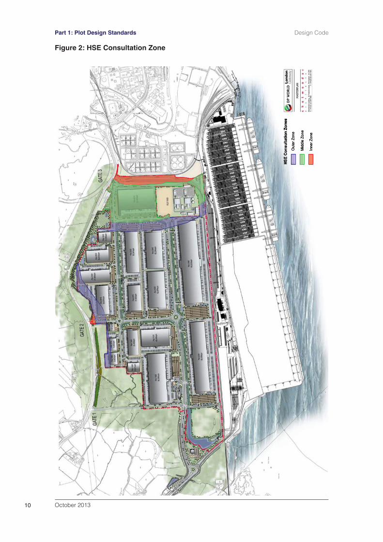
A1.4 Plots in the Health and Safety Executive Inner Zones (IZ) for the petrol storagesite and gas pipelines as shown on Figure 2 shall only be released where:
the number of occupants in each building is less than 100 and the buildinghas less than 3 occupied storeys.it will be used for parking (cars or HGVs) or rail sidings serving the Parkdevelopment.
A1.5 Plots within the HSE middle or outer zone as shown on Figure 2 shall be limitedto B8 use.
A2 Building Size
A2.1 The maximum gross internal floorspace of buildings shall not exceed150,000sq.m.
A2.2 The minimum gross internal floorspace of buildings shall not be less than1,000sq.m (unless for ancillary uses).
A2.3 The gross internal floorspace of Plots adjacent to the northern boundary shallgenerally be between 1,000sq.mand 50,000sq.m.
A2.4 ʻGross Internal Floorspaceʼ is equivalent to ʻGross Internal Areaʼ as calculated inaccordance with the RICS Code of Measuring Practice (sixth edition).
A2.5 Mezzanine floors shall contribute towards overall gross internal floorspace unlessthey are solely to provide for safe and efficient access to stacked or stored goods.
A2.6 Buildings shall maintain a minimum separation distance of at least 8m to the plotboundary.
October 2013 9
Design Code Part 1: Plot Design Standards
October 201310
Part 1: Plot Design Standards Design Code
Figure 2: HSE Consultation Zone

A3 Height
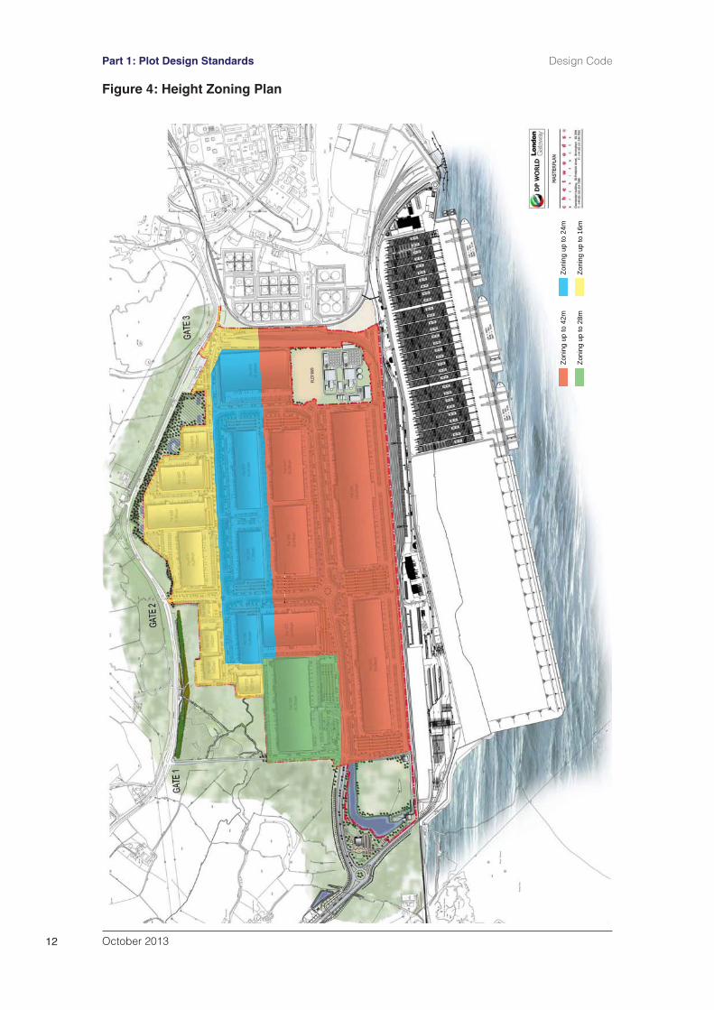
A3.1 Development shall not exceed the maximum height for the zone/plot in which thebuilding is to be located as shown on the height zoning plan (Figure 4) and shallnot exceed the height in AOD set out below:
16m zone = 21.1 AOD24m zone = 29.1 AOD28m zone = 33.1 AOD42m zone = 47.1 AOD
A3.2 Building height shall be measured from the warehouse finished floor slab (beinggenerally between 1000mm and 1500mm above external levels to accommodatemechanical handling equipment - see Figure 3). Within this height there will be aclear internal height to haunch, roof pitch and (if required) 1100mm roof edgesafety barrier zone. This measurement excludes nominal vent and flue protrusionsup to 700mm above roof covering.
Finished Floor Levels
A3.3 The finished floor level (FFL) within the buildings shall be set between 1000mmand 1500mm above the ground level in the dock levelling bays.
October 2013 11
Design Code Part 1: Plot Design Standards
Figure 3: Building Height
October 201312
Part 1: Plot Design Standards Design Code
Figure 4: Height Zoning Plan
Zoni
ng u
p to
42m
Zoni
ng u
p to
28m
Zoni
ng u
p to
24m
Zoni
ng u
p to
16m

A4 General Cladding and Roofing Principles
A4.1 A palette of different materials shall be used in order to achieve articulation andtexture in the overall appearance of the area.
A4.2 The visual impact of the colours and finishes of wall and roof cladding materialsshall be considered in relation to the background and context of the building.Commercial buildings will be sited against the Port backdrop of multi-colouredshipping containers, or against the sky on the horizon or otherwise will be viewedin a generally flat and open landscape.
A4.3 Where buildings over 100,000sq.m are proposed, colours and tones that differfrom those of adjacent buildings shall be encouraged to help break up thecollective visual mass of a group of buildings and give visual texture to the areawhen viewed from long distances.
A4.4 Elevations shall be divided horizontally above the door zone reducing the overallscale of the walls. A minimum of two different cladding profiles laid eitherhorizontally or vertically and two complimenting cladding colours shall be usedon both the warehouse and office elevations to achieve a level of consistentelevational treatment around the Park development. Individual occupieroperational requirements for canopies over docking bays (if required) shall provideadditional articulation of the elevations. Smaller areas of corporate colourationshall be reserved for office elevations fronting onto the internal highway corridors.
A4.5 Elevations shall be punctuated with a range of coloured sectional overheadloading and access doors either at grade or in conjunction with lowered docklevelled service yards. At least one additional colour shall be selected from amanufacturers standard range of colours to compliment the warehouse claddingcolour scheme and tie in with corporate colours on the office elevations.
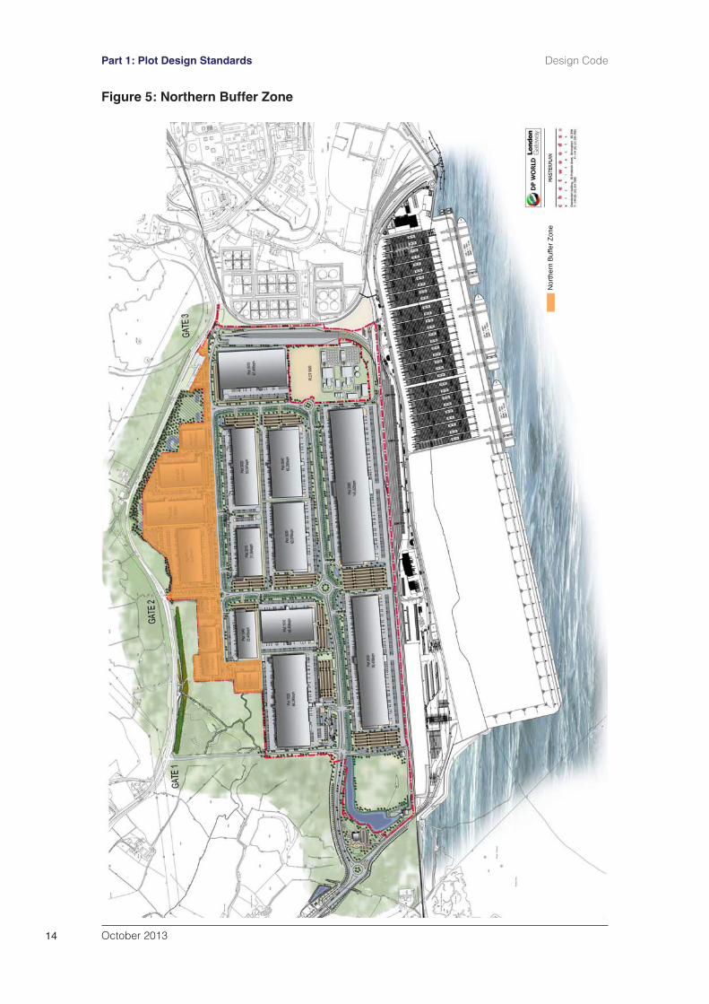
A4.6 For buildings in the northern buffer zone as shown on Figure 5, the elevationsthat face sensitive surrounding areas shall be light in colour and shall reflect thetreatment of other elevations as a minimum. The overall massing of the buildingsalong this zone shall be reduced with the use of barrel vault and/or non-parapetpitched roofs. The use of natural materials such as timber cladding on officeelevations shall be encouraged. This design approach, along with the strategicuse of landscaping, will allow the buildings to blend in with their surroundings.Elevations that have aspects onto the interior of the site can be of brighter coloursto highlight company identity and complement port and introspective views.Where practical, the ʻhigh bayʼ areas of distribution units shall be orientatedtowards the centre of the Site.
A4.7 Large industrial and warehouse units shall typically be constructed from eitherprefabricated composite insulated metal panels or sheets of profiled steel oraluminium, spanning between primary or secondary steel frames and claddingrails.
A4.8 External wall cladding shall be either Loss Prevention Council (LPC) certifiedGrade B composite panels or a built up system with external coating to provide aminimum 25 year guarantee (Confidex or equal). Colours shall be from thestandard range set out below, achieving a ʻuʼ value at least in compliance withbuilding regulations.
October 2013 13
Design Code Part 1: Plot Design Standards
October 201314
Part 1: Plot Design Standards Design Code
Nor
ther
n B
uffe
r Zon
e
Figure 5: Northern Buffer Zone
HPS200 Cladding Finish Colorcoat HPS200 Ultra (or similar) with Galvalloy substrate and ConfidexGuarantee from Tata Steel Standard colours with a minimum 25 yearguarantee from the Signature, Classic and Matt colour ranges (appropriatein coastal locations) shall be selected.
Prisma Cladding FinishColorcoat Prisma (or similar) with Galvalloy substrate and ConfidexGuarantee from Tata Steel Standard colours with a minimum 25 yearguarantee from the Solid and Metallic colour ranges (appropriate in coastallocations) shall be selected.
A4.9 Doors and dock sheltered openings shall be set within a plinth zone of claddingor pre-cast concrete panels designed to withstand or be protected from increasedlevels of impact damage and toned to integrate with the components at the baseof the building and to reduce the overall visual mass of the structure.
A4.10 Vertical features such as exposed rainwater pipes and panel joints may be usedto reduce the horizontal extent of any elevation and provide points of visualreference.
A4.11 Any extension or alteration to a building shall have a similar external appearanceto the existing building.
A5 Dock Levellers and Level Access Doors
A5.1 Dock levellers may be provided in each unit generally at a ratio of 1 per 929sq.mfor single sided facilities and 1 per 464.5sq.m for cross-dock facilities. Levelaccess loading doors may be provided at 1 per 4,645sq.m for single sidedfacilities and 1 per 2,322.5sq.m for cross dock facilities. Ratios within smallerscale units shall be increased to accommodate market demand.
A5.2 Dock levellers shall be provided, as required, with flexible shelters to minimisethe ingress of air and water into the building. Shelters shall generally be black incolour. Insulated sectional overhead doors shall include safety windows and shallbe coloured to suit the overall elevational treatment, or reflect corporate identity.The low level position of these features on the elevation shall allow the perimeterlandscaping to provide effective screening.
A6 Ancillary Office Accommodation
A6.1 Offices shall be designed to maximise the use of natural ventilation and light.Double depth offices with links into the main warehouse area, where required,would be acceptable.
A6.2 Ancillary offices shall be positioned on prominent elevations or corners ofbuildings fronting onto internal highway corridors. Office elevations shall bedistinctive to assist legibility for example through the use of entrance canopies ortimber cladding. A freestanding office pod may also be provided on-plot providedit is ʻpurpose designedʼ to compliment the design of the principal building.
A6.3 Glazing shall be provided to all floors of the offices. Entrance door sets for staffand visitors may either be combined or separated to suit operational
October 2013 15
Design Code Part 1: Plot Design Standards
requirements. Routes to the offices from the car park and footpaths shall bedefined.
A7 Roofscape and Plant
A7.1 Roof planes set at low pitches (6 degrees) shall generally be specified with rooflights at 15% where operational requirements permit, to provide natural light tothe warehouse. Alternatively equivalent natural light may be provided by theinclusion of some translucent wall panels. Roof mounted plant excluding roof
mounted PV, flues and vents shall require screening behind a parapet wall, orintegration within office or warehouse components to maintain clean horizontalroofscapes.
A7.2 Roof form and cladding colours should allow for variation in order to disaggregatethe mass of roof areas but shall be light in colour. External coating shall providea minimum 25 year guarantee (Confidex or equal). Colours from the standardrange of colours referred to in paragraph A4.8 shall be selected and finished innon-reflective coatings.
Fixed Plant
A7.3 Fixed plants such as chiller units on noise sensitive elements (considered mostlikely to be offices and restrooms) within and between each plot shall comply withappropriate British standards for these noise sensitive spaces, includingBS8233:1999.
A7.4 Chiller units shall be located on the facade of warehouses facing into the site, toprevent a direct line of sight to the closest properties. Where this is not possible,in order to reduce noise impacts at the most affected properties, it isrecommended that chiller units and any other ventilation ducts should be limitedto less than 85 dB(A) at 1 metre.
A7.5 General working practices shall be put into place to minimise the levels of noiseincluding:
Awareness training for all staff on noise, particularly noise at night.Staff input into methods of improving the noise environment.Audit of the noise being generated during operations by foremen andsteps taken to enhance the measures to control noise.The use of radios for communications instead of verbal instructions.Consideration of the use of an alternative to reversing alarms and limitson the use of horns for emergency purposes only.
A8 External Building and Site Signage
A8.1 All signage and advertisements on the Site shall be subject to the Town andCountry Planning (Control of Advertisements) (England) Regulations 2007 asamended.
A8.2 Building signage shall be limited to strategic elevations fronting onto theinfrastructure corridor where it will inform vehicles and pedestrians on the internalroad network.
October 201316
Part 1: Plot Design Standards Design Code
A8.3 Key signage shall not be permitted above eaves and shall be in scale with theelevations of the building. No display signage unrelated to the corporate nameshall be allowed on the building elevations, or within the development site.
A8.4 Development plots shall be signposted within the infrastructure corridors, withoccupier signage limited to a position at the thresholds of the site.
A8.5 All illuminated site signage shall incorporate controls to minimise energyconsumption and light pollution.
A9 Gatehouses
A9.1 Gatehouses shall be constructed to the material specification or similar standardto that set out in Section A4.8.
A10 Sustainable Design Standards
Decentralised, Renewable And Low-Carbon Energy Generation
A10.1 All development shall be designed so as not to preclude connection to adecentralised, renewable or low carbon energy supply where possible.
A10.2 As a minimum, new development shall provide the following proportions ofpredicted energy requirements from all sources of decentralised and renewableor low-carbon energy, unless it can be demonstrated that it is not feasible orviable:
10% from 2010;15% from 2015; and20% from 2020.
BREEAM Standards
A10.3 Where appropriate buildings shall achieve as a minimum the following BREEAMstandards (or equivalent), or other such revised standard as may be included inthe Thurrock Core Strategy / Local Plan or other local policy documents:
BREEAM Very Good up to 2016;BREEAM Excellent from 2016;BREEAM Outstanding from 2019 (in addition to national standards for zero carbon).
A10.4 These requirements may be relaxed where the developer is able to prove thatthey are not economically viable, rendering development of the site undeliverable.
A10.5 The above timescales refer to the point at which the prior notification procedureis commenced.
October 2013 17
Design Code Part 1: Plot Design Standards
B Roads, Parking and Access
B1.0 The following design standards shall apply to the construction of internal plotaccess roads, plot-based vehicle parking and servicing.
B1 Plot Access
B1.1 The design of access roads into individual development plots shall comply withthe standards for access visibility set out in the Design Manual for Roads andBridges (DMRB).
B1.2 Pedestrian, cycle and car access to individual plots from the internal site highwaynetwork shall be designed to provide separation from goods vehicles and railroutes, for safety and security purposes and to prevent queuing of goods vehicleson the estate roads.
B1.3 Plot accesses onto the road will be a minimum of 90m apart when on the sameside of the road.
B1.4 To meet health, safety and security requirements on development plots, footpathsand cycleways shall be terminated at the plot threshold and internal plot layoutsshall be designed to accommodate individual occupier requirements whilstmaintaining safe routes to the buildings for pedestrians.
B1.5 Security fences or gates shall not obscure sight lines of any junction on the estateroads or any vehicular access to the highway.
Gatehouses
B1.6 Security gatehouses, or gates to occupier requirements, shall be designed toaccommodate incoming queuing goods vehicles whilst maintaining a free flow ofcars and cycles to designated parking areas. Security gates or gatehouses at theentrance to individual plots shall be set back to enable at least two HGVs to drawoff the highway to avoid queuing on any of the estate roads.
B2 Plot Based Vehicle Servicing
B2.1 The internal plot circulation may be designed to allow cross docking to the largerunits and perimeter access for emergency services. Full site circulation shall bemaintained on larger units in compliance with Building Regulation requirements.
B2.2 Smaller units may be designed with single sided access and a reducedpercentage of perimeter circulation in accordance with Building Regulationrequirements.
B2.3 HGV parking and yard circulation areas shall be in accordance with therecommendations of the Freight Transport Association - designing for deliveries (as amended). Typically 16.5m x 3.5m HGV parking space with a 20mpullout/yard circulation zone.
B2.4 HGV circulation on plot shall be designed to allow free flowing circulation to allexternal areas of the building required by the unit operator, either through theservice yards or via a minimum 7.3m wide plot circulation roads.
October 201318
Part 1: Plot Design Standards Design Code
B2.5 Where fire escape routes from buildings open onto service yard areas, protectedescape steps and refuges shall be provided between lorry docking and parkingbays.
HGV Fuel facility
B2.6 All areas of hard standing shall be provided with a surface water drainage systemfitted with oil and petrol interceptors.
B2.7 External HGV fuelling facilities shall not exceed a maximum plot coverage of 3%or 3,000sq.mwhichever is the lesser. Fuel storage tanks shall be double skinnedand may be either below or above ground. Fuelling pumps shall either be openor covered with a canopy with a minimum clear height of 6m and a maximumheight to the top of the canopy of 9m and shall be appropriately landscaped. HGVfuelling facilities shall be located in service yards or adjacent to on-plot circulationroutes provided they are appropriately screened.
HGV Wash facility
B2.8 External HGV wash facilities shall not exceed a maximum plot coverage of 1% or1,000sq.m whichever is the lesser. Wash facilities may either be open or coveredwith a maximum height to the top of the enclosure of 7m. However, surface watershould be excluded from the wash system, so a covered area would bepreferable.
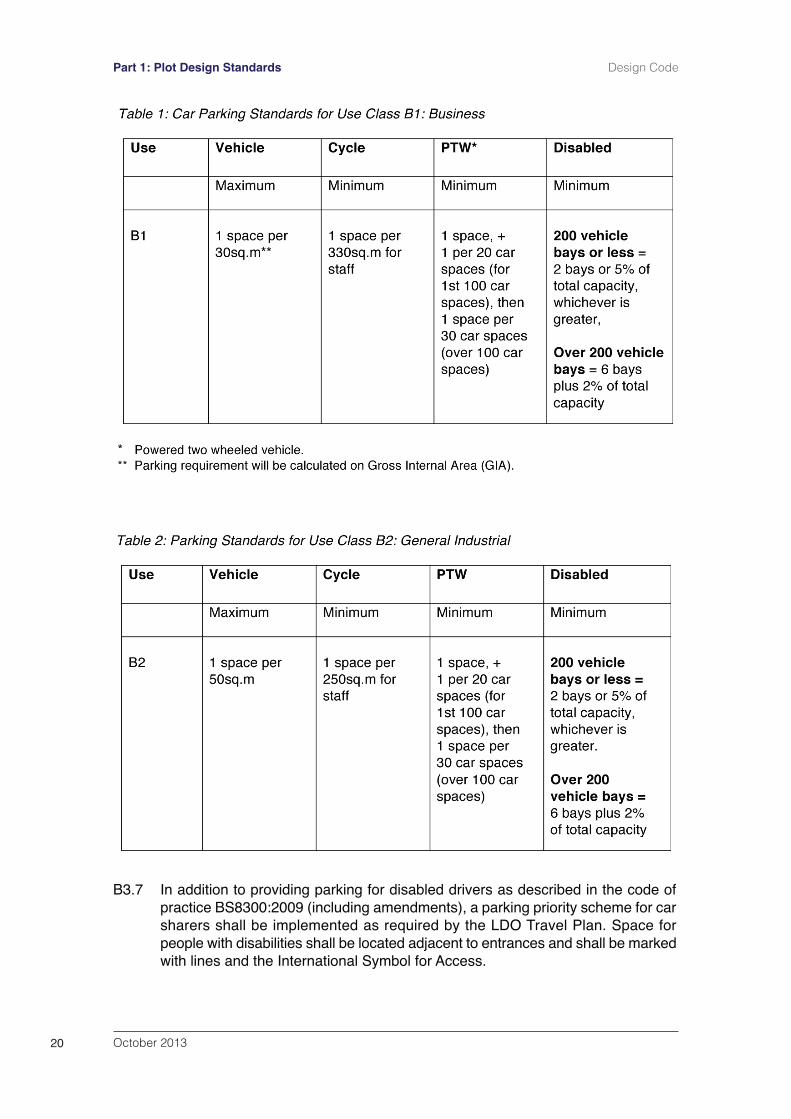
B3 Parking Standards
B3.1 Individual development plots shall be designed to achieve optimum vehicleparking requirements and to prevent vehicles queuing on the highway whilewaiting to enter the development plots.
B3.2 Car parking shall be provided on each plot in accordance with the standardsspecified in Tables 1 – 4 below and shall be made available for use during thewhole of the time that any part of a building is open to any persons employedwithin the building or to persons visiting the building.
B3.3 If office accommodation is included in the development then a B1 parkingstandard shall be applied for that area.
B3.4 Where a development incorporates two or more land uses to which differentparking standards are applicable, the standard appropriate to each use shall beapplied in proportion to the extent of the respective use.
B3.5 The width of standard parking bays with end bays adjacent to solid structuresshall be increased by 1m to allow for maneuverability on entry/exit to and fromthe vehicle. Clear directional marking signs shall be set out using suitable signsand surface arrows.
B3.6 Landscaping shall be incorporated into parking areas as set out in C4 of thisDesign Guide.
October 2013 19
Design Code Part 1: Plot Design Standards
B3.7 In addition to providing parking for disabled drivers as described in the code ofpractice BS8300:2009 (including amendments), a parking priority scheme for carsharers shall be implemented as required by the LDO Travel Plan. Space forpeople with disabilities shall be located adjacent to entrances and shall be markedwith lines and the International Symbol for Access.
October 201320
Part 1: Plot Design Standards Design Code
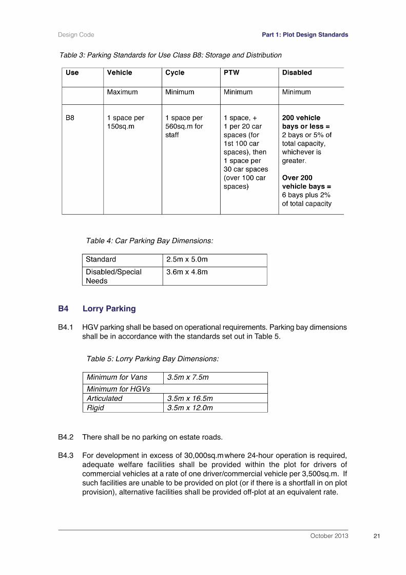
B4 Lorry Parking
B4.1 HGV parking shall be based on operational requirements. Parking bay dimensionsshall be in accordance with the standards set out in Table 5.
B4.2 There shall be no parking on estate roads.
B4.3 For development in excess of 30,000sq.mwhere 24-hour operation is required,adequate welfare facilities shall be provided within the plot for drivers ofcommercial vehicles at a rate of one driver/commercial vehicle per 3,500sq.m. Ifsuch facilities are unable to be provided on plot (or if there is a shortfall in on plotprovision), alternative facilities shall be provided off-plot at an equivalent rate.
October 2013 21
Design Code Part 1: Plot Design Standards
B5 Cycle Parking
B5.1 All cycle parking shall:
be secure and covered;be conveniently located adjacent to entrances to buildings;enjoy natural observation;be easily accessible from roads/and or cycle routes;be well lit;be located so not to obstruct pedestrian and cycle routes.
B5.2 Sheffield stands or similar shall normally be provided. Provision shall be madefor lockers, changing and shower facilities. The location, type and dimensions forcycle parking shall accord with the Essex Parking Standards 2009 or other suchstandards adopted by Thurrock Council.
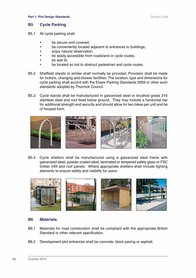
B5.3 Cycle stands shall be manufactured in galvanized steel or brushed grade 316stainless steel and root fixed below ground. They may include a horizontal barfor additional strength and security and should allow for two bikes per unit and beof hooped form.
B5.4 Cycle shelters shall be manufactured using a galvanized steel frame withgalvanized steel, powder coated steel, laminated or tempered safety glass or FSCtimber infill and roof panels. Where appropriate shelters shall include lightingelements to ensure safety and visibility for users.
B6 Materials
B6.1 Materials for road construction shall be compliant with the appropriate BritishStandard or other relevant specification.
B6.2 Development plot entrances shall be concrete, block paving or asphalt.
October 201322
Part 1: Plot Design Standards Design Code
B6.3 Standard profile concrete kerbs shall be used adjacent to footpaths / cyclewaysand within car parking areas. High profile concrete kerbs shall be used withinareas susceptible to HGV damage.
B6.4 Road marking and parking bays shall be demarcated in white or yellowthermoplastic paint and kerbs shall be used to provide protection to pedestrianareas and prevent damage to landscaped areas by vehicles.
B6.5 When available, suitably recycled, locally sourced or ʻgreen energyʼ materialsshall be used where these conform to the necessary standards and will meet thenecessary performance standards or specification.
B7 Standards for Footpaths and Cycleways
B7.1 Shared use footways/cycleways shall be a minimum width of 3m.
B7.2 Where footways/cycleways are liable to vehicle over-run, materials shall berestricted to:
Bituminous materials to DMRB standards unless there is a need to matchexisting paths surfaced with Hot Rolled Asphalt (HRA). Resin bound material - Highways Authorities Product Approval Scheme(HAPAS) certified with a minimum design life of 25 years.Where appropriate, concrete block paving, including tumbled blocks, 100mmx 200mm x 80mm.
B7.3 Where the footway will not be over run or otherwise damaged by vehicles thefollowing paving may be used in addition to that noted above.
400mm x 400mm x 65mm standard concrete paving slabs.400mm x 400mm x 65mm textured concrete paving slabs.
B8 Lighting
General Considerations
B8.1 The following standards apply to all exterior lighting across the site. Referencesto lighting equipment are indicative and may be amended subject to achievingthe stated performance requirements.
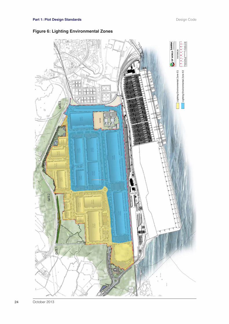
B8.2 Lighting equipment when installed, shall meet the lighting constraints defined inILP Guidance Notes GN01 for the control of obtrusive light for the EnvironmentalZone applicable to the location of the site (see Figure 6). Additional care shall betaken to minimise light spill and glare from any lighting installed by ensuring thecorrect luminaire is selected and installed correctly in line with therecommendations within CIE 150 (2003) and ILP GN01. The design shall ensurethe mounting heights employed are the minimum necessary to achieve thelighting performance requirements. Illuminance levels shall not exceed 1.0 lux at25m and 0.1 lux at 50m from the perimeter site boundary to the Park. Themanagement company, London Gateway Services Limited (LGSL), shall monitorilluminance levels at 50m intervals at points 25m and 50m from the northern andwestern perimeter site boundaries on at least one occasion between 1 November
October 2013 23
Design Code Part 1: Plot Design Standards
October 201324
Part 1: Plot Design Standards Design Code
Ligh
ting
Env
ironm
enta
l Zon
e E
1
Ligh
ting
Env
ironm
enta
l Zon
e E
2
Figure 6: Lighting Environmental Zones
and 1 March each year and report their findings to the Environmental AdvisoryGroup (EAG). LGSL shall take whatever steps necessary to ensure compliancewith the standards set out above. In the event that any remedial action is required,LGSL shall undertake a further round of monitoring within 14 days of any breachbeing identified to demonstrate to the satisfaction of the EAG that the standardsare being complied with.
B8.3 The lighting units shall be controlled so that they can be dimmed or switched offin defined work areas should operational conditions allow, subject to Health andSafety requirements, for example staff parking areas outside of shift change times.All lighting may be operated at full output throughout the hours of darkness.
B8.4 Lighting within the development shall use white light sources with a ColourRendering Index, Ra >60 throughout. For the purpose of standardisingmaintenance spares, the lighting units shall be fitted with Philips CPO-TWCosmoPolis ceramic metal halide lamps or similar.
B8.5 The use of LED lighting may be a viable alternative to the CosmoPolis lamp insome situations on the condition that it is able to achieve an equivalentphotometric performance within a luminaire having similar aesthetics to thoseproposed in the following sections. This particularly applies where the Urbis Furyorange of lanterns is to be used.
Lighting Controls
B8.6 The exterior lighting shall be remotely controlled and monitored by a CentralManagement System (CMS) such as the Harvard Engineering Leafnut/LucyZodion Vizion or similar.
Power Distribution
B8.7 The exterior lighting shall be supplied by a private cable network fed from feederpillars mounted externally or from distribution panels within the buildings. Cablingshall be installed in buried ducts.
B8.8 Where lighting units are mounted on walls of buildings, cabling shall be installedwithin corrosion and impact resistant conduit or trunking.
B8.9 Power supplies and cabling for lighting within the Park shall be fully segregatedfrom Thurrock Council owned lighting equipment.
B8.10 Columns should be mounted a safe distance from carriageways for maintenanceaccess, free pedestrian and cycle passage and to reduce collisions in accordancewith the requirements of clauses 3.3 and 3.4 respectively of TD 34/07 of theDMRB.
Lighting Classes
B8.11 The lighting classes for roads, footways and cycleways shall be as set out in BS5489-1: 2013 Code of Practice for the Design of Road Lighting – Part 1: Lightingof roads and public amenity areas, or as subsequently modified, and BS EN
October 2013 25
Design Code Part 1: Plot Design Standards
13201:2003 Road Lighting. The lighting classes for outdoor work areas wouldbe as set out in BS EN 12464-2:2007 Light and Lighting – Lighting of workplaces;Part 2: Outdoor work places.
On Plot Circulatory Roads
Performance Requirements
B8.12 The lighting of on plot circulatory roads shall be designed to lighting class S2. Theperformance requirement applying a S/P ratio of 1.2 is:
Average illuminance, Eav: 10.0 to 15.0 luxMinimum illuminance, Emin: 2.0 lux minimum
B8.13 This level can be further reduced dependent upon the Ra value and the S/P ratioof the lamp in accordance with Clause A 3.3.3 of BS5489-1: 2013.
Equipment Details
B8.14 Luminaire and lamp: Urbis Furyo 2 lantern or equivalent with 90W CPO-TW
Lighting column and bracket: Urbis FLO column and Bracket or equivalent of 8m maximum height.
Mounting attitude: Zero inclination
Installation Geometry
B8.15 Single Carriageway: Lighting columns shall be mounted in a single sidedarrangement at the rear of the cycleway/footway at a nominal longitudinal spacingof 22m.
Lorry Docking and Loading Areas
B8.16 The lighting shall be in accordance with HSG 38, and 5.1.4 and 5.7.2 of BS12464-2: 2007.
Lorry Docking and Loading Areas
Performance Requirements
Average illuminance: 50 luxOverall Uniformity, Uo: 0.40Glare Rating Limit, GRL: 50
B8.17 Glare to a driver reversing a vehicle shall be avoided and shadowing caused bythe vehicle load shall be considered. Glare visible outside the perimeter siteboundary of the Park shall be avoided
Lighting Arrangement
B8.18 Lighting units shall be mounted on the wall of the building. The lightingarrangement for a typical docking and loading area is shown on Figure 7. Building
October 201326
Part 1: Plot Design Standards Design Code
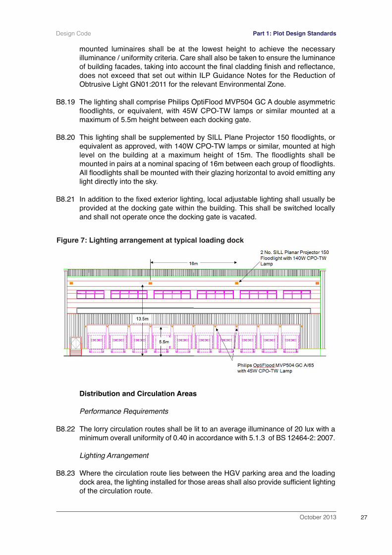
mounted luminaires shall be at the lowest height to achieve the necessaryilluminance / uniformity criteria. Care shall also be taken to ensure the luminanceof building facades, taking into account the final cladding finish and reflectance,does not exceed that set out within ILP Guidance Notes for the Reduction ofObtrusive Light GN01:2011 for the relevant Environmental Zone.
B8.19 The lighting shall comprise Philips OptiFlood MVP504 GC A double asymmetricfloodlights, or equivalent, with 45W CPO-TW lamps or similar mounted at amaximum of 5.5m height between each docking gate.
B8.20 This lighting shall be supplemented by SILL Plane Projector 150 floodlights, orequivalent as approved, with 140W CPO-TW lamps or similar, mounted at highlevel on the building at a maximum height of 15m. The floodlights shall bemounted in pairs at a nominal spacing of 16m between each group of floodlights.All floodlights shall be mounted with their glazing horizontal to avoid emitting anylight directly into the sky.
B8.21 In addition to the fixed exterior lighting, local adjustable lighting shall usually beprovided at the docking gate within the building. This shall be switched locallyand shall not operate once the docking gate is vacated.
Distribution and Circulation Areas
Performance Requirements
B8.22 The lorry circulation routes shall be lit to an average illuminance of 20 lux with aminimum overall uniformity of 0.40 in accordance with 5.1.3 of BS 12464-2: 2007.
Lighting Arrangement
B8.23 Where the circulation route lies between the HGV parking area and the loadingdock area, the lighting installed for those areas shall also provide sufficient lightingof the circulation route.
October 2013 27
Design Code Part 1: Plot Design Standards
Figure 7: Lighting arrangement at typical loading dock
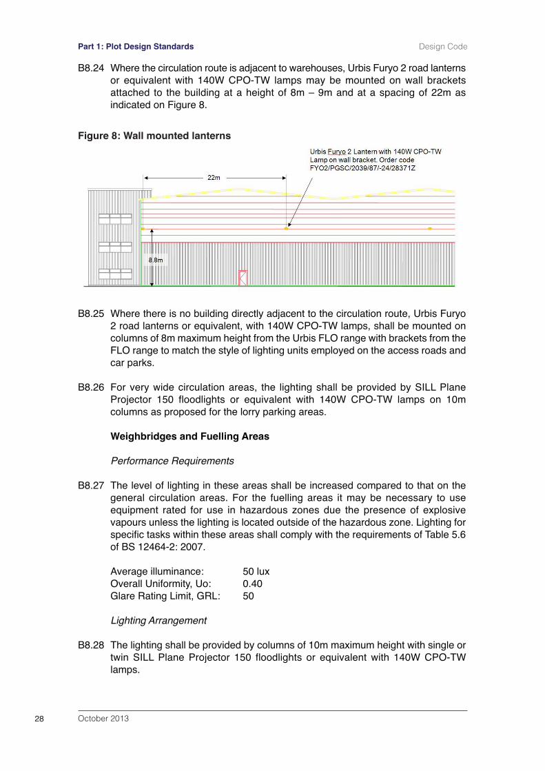
B8.24 Where the circulation route is adjacent to warehouses, Urbis Furyo 2 road lanternsor equivalent with 140W CPO-TW lamps may be mounted on wall bracketsattached to the building at a height of 8m – 9m and at a spacing of 22m asindicated on Figure 8.
B8.25 Where there is no building directly adjacent to the circulation route, Urbis Furyo2 road lanterns or equivalent, with 140W CPO-TW lamps, shall be mounted oncolumns of 8m maximum height from the Urbis FLO range with brackets from theFLO range to match the style of lighting units employed on the access roads andcar parks.
B8.26 For very wide circulation areas, the lighting shall be provided by SILL PlaneProjector 150 floodlights or equivalent with 140W CPO-TW lamps on 10mcolumns as proposed for the lorry parking areas.
Weighbridges and Fuelling Areas
Performance Requirements
B8.27 The level of lighting in these areas shall be increased compared to that on thegeneral circulation areas. For the fuelling areas it may be necessary to useequipment rated for use in hazardous zones due the presence of explosivevapours unless the lighting is located outside of the hazardous zone. Lighting forspecific tasks within these areas shall comply with the requirements of Table 5.6of BS 12464-2: 2007.
Average illuminance: 50 luxOverall Uniformity, Uo: 0.40Glare Rating Limit, GRL: 50
Lighting Arrangement
B8.28 The lighting shall be provided by columns of 10m maximum height with single ortwin SILL Plane Projector 150 floodlights or equivalent with 140W CPO-TWlamps.
October 201328
Part 1: Plot Design Standards Design Code
Figure 8: Wall mounted lanterns
Gatehouses
Performance requirements
B8.29 Gatehouses shall be lit to an average illuminance of 100 lux at ground level witha vertical illuminance at the level of the vehicle driver. Gatehouse security lightingshall be in accordance with the recommendations provided in sections 18.3 and18.4 of the CIBSE SLL Lighting Handbook (2009) as may be amended.
B8.30 The entrance shall be lit by multiple luminaires so that the loss of one luminairewill not seriously degrade the lighting available to the guard on duty. The lightingshall be positioned to enable sufficient illumination for the guards and CCTV tosee the number plates of vehicles approaching the entrance.
Lighting Arrangement
B8.31 The proposed lighting shall comprise lighting columns of 8m maximum height with4 no. SILL Plane Projector 150 floodlights or equivalent equipped with 140WCPO-TW lamps. The floodlights shall be mounted with their glazing horizontal toprovide a full cut-off of light above the horizontal. Consideration shall be given toproviding back-up power supplies for these lighting units in the event of a poweroutage.
Car and Van Parking Areas
Performance Requirements
B8.32 The lighting of the car and van parking areas shall meet the requirements in Table5 of BS 5489-1 for outdoor car parks with heavy traffic.
B8.33 The performance requirements shall be as follows:
Average illuminance, Eav: 20 luxOverall Unifomity, Uo: 0.25 minimum
Equipment Details
Luminaire and lamp: Urbis Furyo 2 lantern or equivalent with 90W CPO-TW
Lighting column and bracket: Urbis FLO column or equivalent with single and twin bracket arm of 8m maximum height.
Mounting attitude: Zero inclination
Installation Geometry
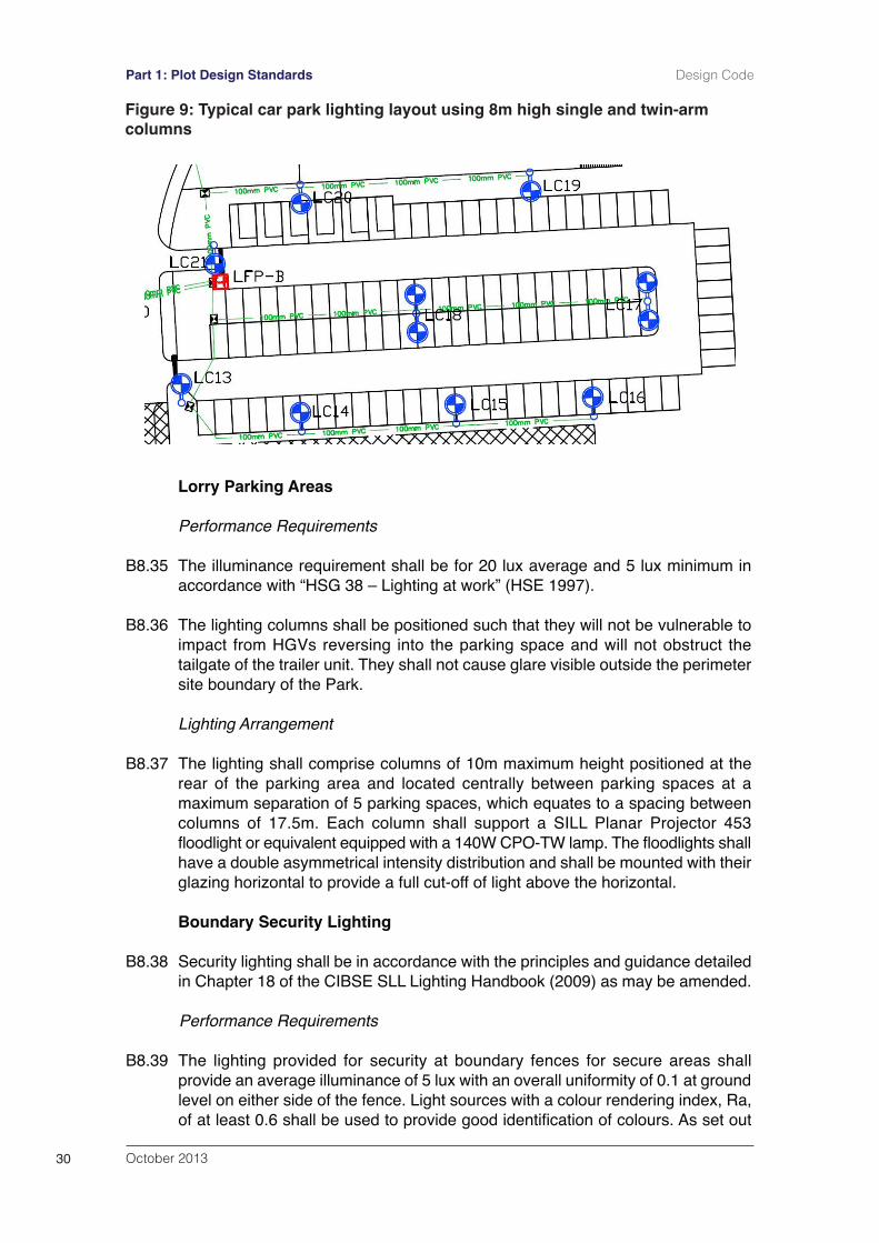
B8.34 Lighting columns shall be mounted around the perimeter of a car park and wherenecessary, within the central area of the parking area. Figure 9 shows a typicalarrangement. Where lighting columns are located within the central area theyshall be generally located on the raised islands at the end of parking space rows,or where it is necessary to position them between parking spaces, with barrierprotection to protect vehicles manoeuvring into them.
October 2013 29
Design Code Part 1: Plot Design Standards
Lorry Parking Areas
Performance Requirements
B8.35 The illuminance requirement shall be for 20 lux average and 5 lux minimum inaccordance with “HSG 38 – Lighting at work” (HSE 1997).
B8.36 The lighting columns shall be positioned such that they will not be vulnerable toimpact from HGVs reversing into the parking space and will not obstruct thetailgate of the trailer unit. They shall not cause glare visible outside the perimetersite boundary of the Park.
Lighting Arrangement
B8.37 The lighting shall comprise columns of 10m maximum height positioned at therear of the parking area and located centrally between parking spaces at amaximum separation of 5 parking spaces, which equates to a spacing betweencolumns of 17.5m. Each column shall support a SILL Planar Projector 453floodlight or equivalent equipped with a 140W CPO-TW lamp. The floodlights shallhave a double asymmetrical intensity distribution and shall be mounted with theirglazing horizontal to provide a full cut-off of light above the horizontal.
Boundary Security Lighting
B8.38 Security lighting shall be in accordance with the principles and guidance detailedin Chapter 18 of the CIBSE SLL Lighting Handbook (2009) as may be amended.
Performance Requirements
B8.39 The lighting provided for security at boundary fences for secure areas shallprovide an average illuminance of 5 lux with an overall uniformity of 0.1 at groundlevel on either side of the fence. Light sources with a colour rendering index, Ra,of at least 0.6 shall be used to provide good identification of colours. As set out
October 201330
Part 1: Plot Design Standards Design Code
Figure 9: Typical car park lighting layout using 8m high single and twin-armcolumns
October 2013 31
Design Code Part 1: Plot Design Standards
300m
Rai
l Saf
egua
rdin
g
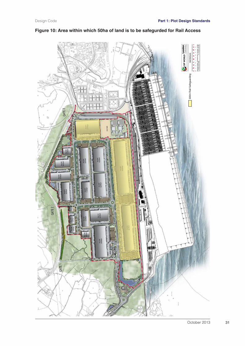
Figure 10: Area within which 50ha of land is to be safegurded for Rail Access
at B8.2, illuminance levels shall not exceed 1.0 lux at 25m and 0.1 lux at 50mfrom the perimeter site boundary to the Park.
Lighting Arrangement
B8.40 Where buildings and other obstructions result in dark shadowing along theboundary, security lighting shall be provided by lighting columns of between 5mand 8m high with Furyo lanterns equipped with CPO-TW lamps or equivalent upto 140W maximum power rating. The exact column height and lamp combinationshall be dependent on the geography of the site and the type of fenceconstruction; 5m high lighting units shall generally be satisfactory.
B9 Plot-by-Plot Rail Connection
B9.1 No development shall take place within an area comprising not less than 50ha ofland situated within a zone 300 metres from either the Thameshaven Branch Lineor the Common User Siding (see Figure 10) without provision having been madefor rail access to the national rail network via the Thameshaven Branch Line(whether directly or via the Common User Siding). No development shall takeplace within the site which would prejudice the provision of such rail access.
October 201332
Part 1: Plot Design Standards Design Code
C Landscaping
C1 Street Furniture
C1.1 Street furniture (e.g. seating, cycle storage etc.) shall be in accordance withrequirements set out at Part 2, Section I3 of this document.
C2 Boundary Treatments
C2.1 Individual occupiers shall be responsible for on site security of their developmentplots. Fencing to the perimeter of each plot shall be designed to be unobtrusivewithin the perimeter of the landscaped zone, with the minimal amount of impacton landscaping.
C2.2 Car parks to individual plots shall be designed to provide an element of naturalsurveillance allowing views from the road. Pedestrian, cycle and car access toindividual plots from the highway network shall be designed to provide separationfrom goods vehicles and rail routes.
C2.3 The height of perimeter fencing shall be a maximum of 3m above ground leveland shall typically be:
BS1722-12 Steel Palisade Fencing; andBS1722- 14 Open Mesh Steel Panel Fencing Category 1 (GeneralPurpose) and Category 2 (Security) Fencing.
C2.4 Posts and struts for all fences shall be manufactured from Black RAL9005 powdercoated galvanised steel and secured with concrete foundations. All fixings andstraining devices shall be zinc coated.
C2.5 All Steel Palisade fencing shall have pale tops shaped in accordance withBS1722-12. Fencing shall not have cranked arms, barbed tape concertina orbarbed wire entanglement topping.
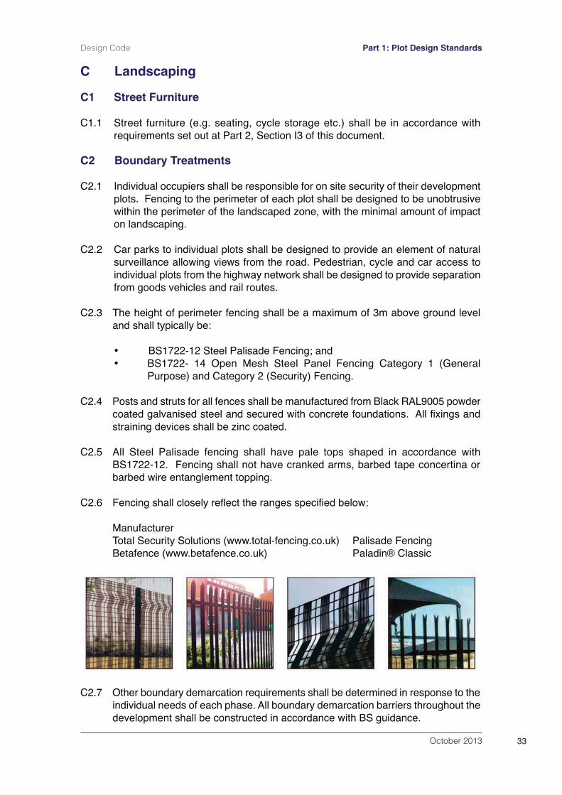
C2.6 Fencing shall closely reflect the ranges specified below:
ManufacturerTotal Security Solutions (www.total-fencing.co.uk) Palisade FencingBetafence (www.betafence.co.uk) Paladin® Classic
C2.7 Other boundary demarcation requirements shall be determined in response to theindividual needs of each phase. All boundary demarcation barriers throughout thedevelopment shall be constructed in accordance with BS guidance.
October 2013 33
Design Code Part 1: Plot Design Standards
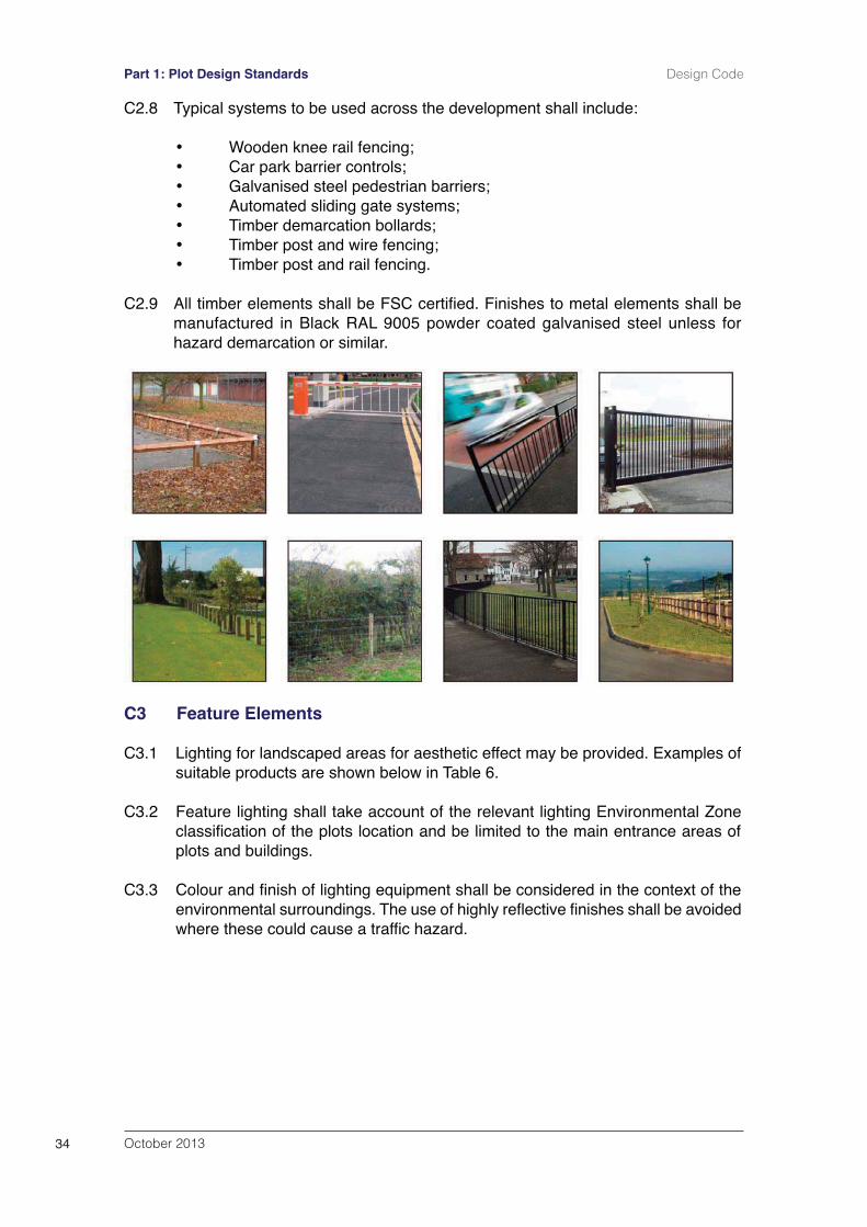
C2.8 Typical systems to be used across the development shall include:
Wooden knee rail fencing;Car park barrier controls;Galvanised steel pedestrian barriers;Automated sliding gate systems;Timber demarcation bollards;Timber post and wire fencing;Timber post and rail fencing.
C2.9 All timber elements shall be FSC certified. Finishes to metal elements shall bemanufactured in Black RAL 9005 powder coated galvanised steel unless forhazard demarcation or similar.
C3 Feature Elements
C3.1 Lighting for landscaped areas for aesthetic effect may be provided. Examples ofsuitable products are shown below in Table 6.
C3.2 Feature lighting shall take account of the relevant lighting Environmental Zoneclassification of the plots location and be limited to the main entrance areas ofplots and buildings.
C3.3 Colour and finish of lighting equipment shall be considered in the context of theenvironmental surroundings. The use of highly reflective finishes shall be avoidedwhere these could cause a traffic hazard.
October 201334
Part 1: Plot Design Standards Design Code
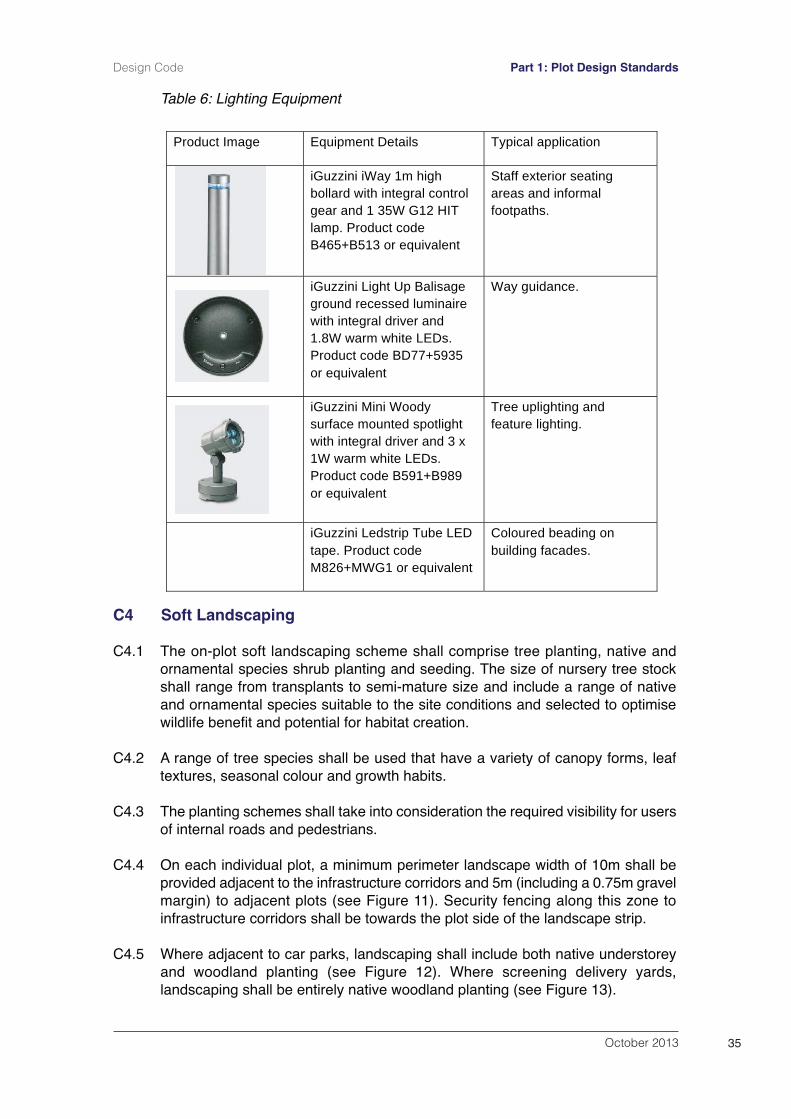
Table 6: Lighting Equipment
C4 Soft Landscaping
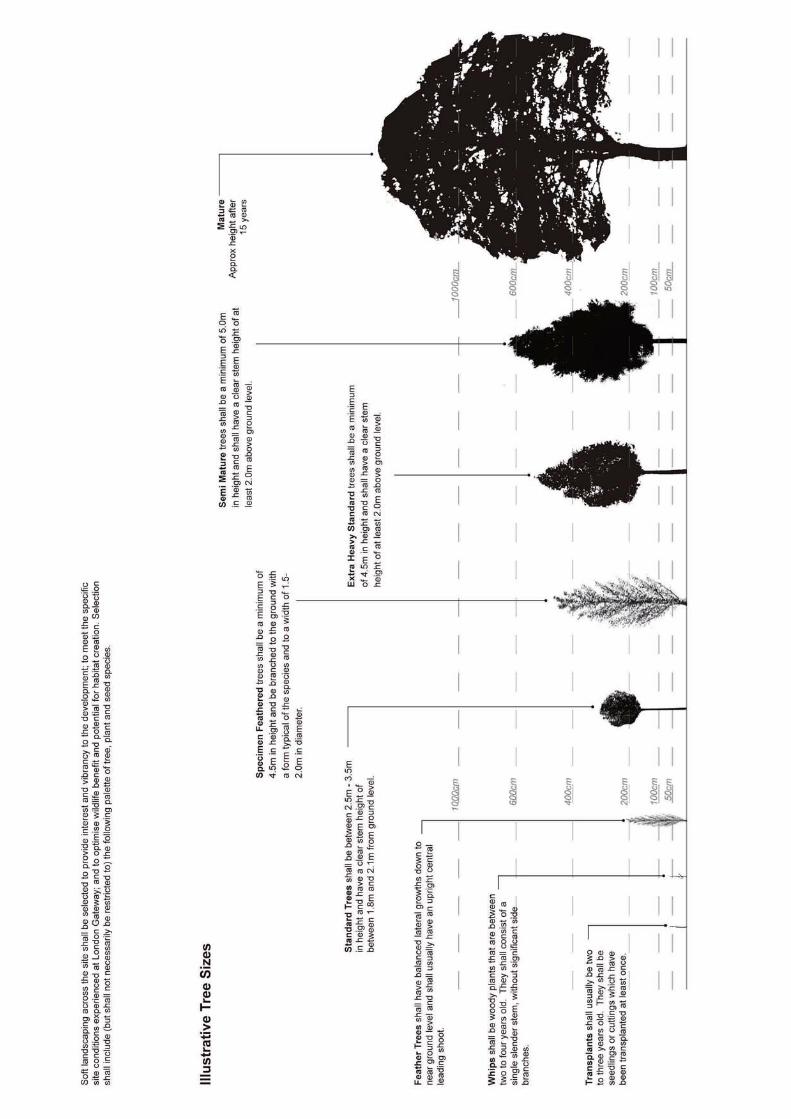
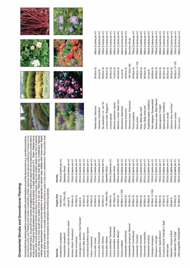
C4.1 The on-plot soft landscaping scheme shall comprise tree planting, native andornamental species shrub planting and seeding. The size of nursery tree stockshall range from transplants to semi-mature size and include a range of nativeand ornamental species suitable to the site conditions and selected to optimisewildlife benefit and potential for habitat creation.
C4.2 A range of tree species shall be used that have a variety of canopy forms, leaftextures, seasonal colour and growth habits.
C4.3 The planting schemes shall take into consideration the required visibility for usersof internal roads and pedestrians.
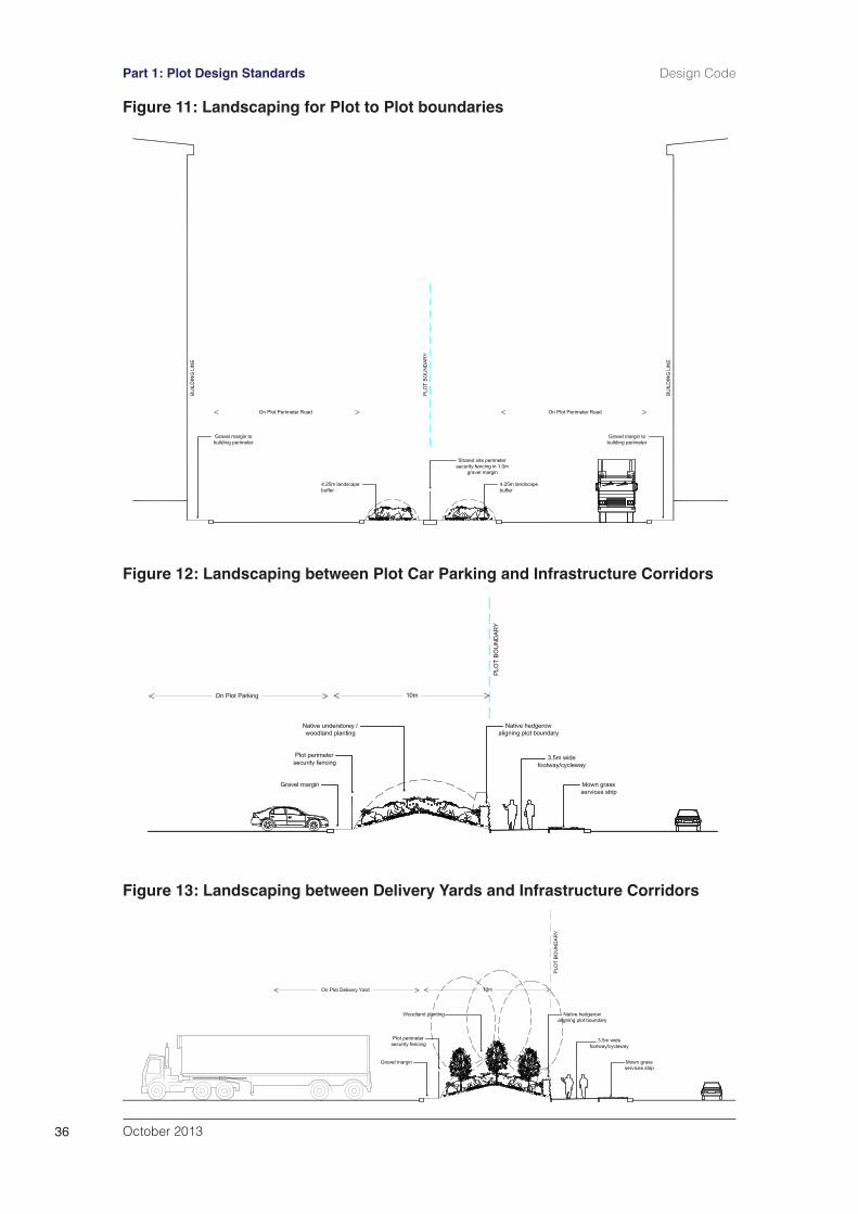
C4.4 On each individual plot, a minimum perimeter landscape width of 10m shall beprovided adjacent to the infrastructure corridors and 5m (including a 0.75m gravelmargin) to adjacent plots (see Figure 11). Security fencing along this zone toinfrastructure corridors shall be towards the plot side of the landscape strip.
C4.5 Where adjacent to car parks, landscaping shall include both native understoreyand woodland planting (see Figure 12). Where screening delivery yards,landscaping shall be entirely native woodland planting (see Figure 13).
October 2013 35
Design Code Part 1: Plot Design Standards
Product Image Equipment Details Typical application
iGuzzini iWay 1m high bollard with integral control gear and 1 35W G12 HIT lamp. Product code B465+B513 or equivalent
Staff exterior seating areas and informal footpaths.
iGuzzini Light Up Balisage ground recessed luminaire with integral driver and 1.8W warm white LEDs. Product code BD77+5935 or equivalent
Way guidance.
iGuzzini Mini Woody surface mounted spotlight with integral driver and 3 x 1W warm white LEDs. Product code B591+B989 or equivalent
Tree uplighting and feature lighting.
iGuzzini Ledstrip Tube LED tape. Product code M826+MWG1 or equivalent
Coloured beading on building facades.
October 201336
Part 1: Plot Design Standards Design Code
Figure 11: Landscaping for Plot to Plot boundaries
Figure 12: Landscaping between Plot Car Parking and Infrastructure Corridors
Figure 13: Landscaping between Delivery Yards and Infrastructure Corridors
C4.6 Ornamental shrub, herbaceous and specimen tree planting shall be includedwithin car parking areas.
C4.7 Development plots shall be tied into the existing landform along their edge at agradient not exceeding 1:3. To help screen delivery yards and built form, the re-graded slopes shall be aligned along their upper edge by standard trees in anative hedgerow. Understorey and woodland planting shall also be establishedon a minimum 50% of the remaining slope area.
C4.8 The soft landscaping scheme for each plot shall be implemented within the firstfull growing season after building completion or occupation whichever is thesooner. New landscaping shall be maintained and remedial action taken asnecessary for five years after planting. Maintenance thereafter shall continue inaccordance with the Landscape Management Plan (Appendix 2).
C4.9 The soft landscaping scheme for plots shall comply with the detailed softlandscaping specification set out at Appendix 1.
C4.10 Plant species in general will include (but will not necessarily be restricted to) thoselisted within Appendix 1.
C5 Landscape Management Plan
C5.1 A coherent, strategic and integrated approach to the management andmaintenance of the soft landscape components associated with the development,shall be adopted in accordance with the Landscape Management Plan set out atAppendix 2 to ensure the successful establishment of vegetation and overallintegration within the surrounding landscape.
C6 External Finishes
C6.1 External finishes shall generally be a selection of concrete, tarmacadam or blockpaviors / paving slabs with road marking and parking demarcated in white / yellowthermoplastic paint. Parking areas shall generally be constructed of semi-permeable paving where practical. Areas of soft landscaping within thedevelopment plots shall be designed with kerb protection to prevent damagecaused by vehicles.
C6.2 High profile kerbing shall be specified within areas susceptible to HGV damage.Landscaping located within car parking areas shall require similar protection fromvehicles and pedestrians.
C7 Earth Shaping and Planting Regime
C7.1 Individual plots shall include earth shaping elements particularly at their perimeterin order to accommodate drainage wetland areas if required as part of thedrainage system and sculptural landform and mounding to enhance enclosureand provide additional interest. To enable safe access for planting / maintenance,slopes shall not exceed a gradient of 1:2 where planted with ornamental shrubspecies and 1:3 in all other locations.
October 2013 37
Design Code Part 1: Plot Design Standards

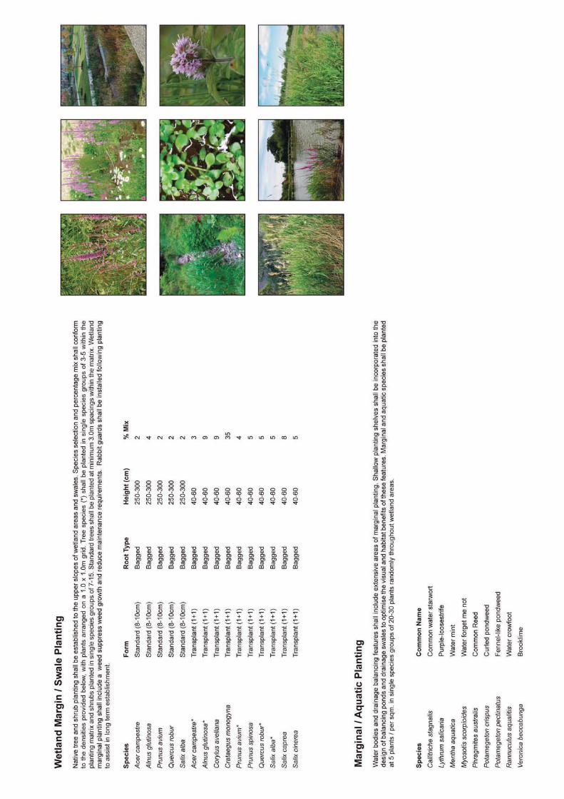
C7.2 On plot water bodies shall generally be located away from key pedestrian routes.Water bodies shall contain a combination of planting treatments including blocksof trees and shrub planting, wildflower grassland and marginal aquatic species.
C7.3 The composition of the wildflower seed mix shall include species that are able tothrive in drier conditions at the upper margins of wetlands and damp tolerantvarieties capable of establishing on the lower slopes.
C7.4 Species selection for marginal plants shall be robust and able to cope withchanges in water level. Over time there shall be a subtle adaptation in the plantingscheme in response to fluctuations in water level and management techniques.
C7.5 Where stepped access is provided to water bodies, slopes shall not exceed amaximum gradient of 1:3 to allow for emergency egress from the water.Elsewhere, water bodies shall be designed to accommodate areas where themaximum gradient does not exceed a slope of 1:5.
C7.6 The soft landscaping scheme for plots shall comply with the detailed softlandscaping specification set out at Appendix 1.
Safety
C7.7 Landscaping shall be utilised as a safety barrier to discourage public access tothe ponds. Timber knee rails shall be installed as a guide to pedestrians whereplanting is not otherwise present.
October 201338
Part 1: Plot Design Standards Design Code

D External Areas
D1 External Storage
D1.1 External storage shall not be provided within infrastructure corridors or buildingservice yards fronting the primary site access road except where facilities aresingle sided and the external storage area is situated behind a 10m widelandscaped zone.
D1.2 External storage shall have a maximum plot coverage of 2% or 2,000sq.mwhichever is the lesser and shall not exceed 6m in height and shall be withinfenced areas not exceeding 3m in height.
D2 Ancillary Infrastructure
D2.1 Ancillary infrastructure including permanent plant and equipment necessary tosupport B1, B2 or B8 uses shall be located in service yards. Such plant andequipment may include (but need not be limited to) external:
chiller plants;sprinkler tanks and pumphouses;pneumatics;aerosol stores;compressor housing;generators;generator switchgear enclosures;electricity sub stations;refuse areas; andair conditioning units.
D2.2 Electricity sub stations may also be located on the plot boundary provided theyare appropriately landscaped.
D2.3 The height of ancillary infrastructure shall not exceed the eaves of the associatedbuilding.
October 2013 39
Design Code Part 1: Plot Design Standards
E On-Plot Drainage Standards
E0 Overview
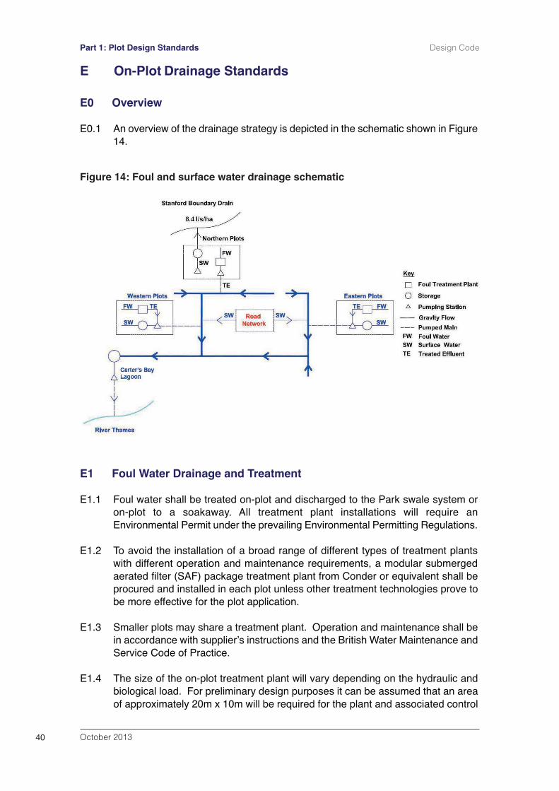
E0.1 An overview of the drainage strategy is depicted in the schematic shown in Figure14.
E1 Foul Water Drainage and Treatment
E1.1 Foul water shall be treated on-plot and discharged to the Park swale system oron-plot to a soakaway. All treatment plant installations will require anEnvironmental Permit under the prevailing Environmental Permitting Regulations.
E1.2 To avoid the installation of a broad range of different types of treatment plantswith different operation and maintenance requirements, a modular submergedaerated filter (SAF) package treatment plant from Conder or equivalent shall beprocured and installed in each plot unless other treatment technologies prove tobe more effective for the plot application.
E1.3 Smaller plots may share a treatment plant. Operation and maintenance shall bein accordance with supplierʼs instructions and the British Water Maintenance andService Code of Practice.
E1.4 The size of the on-plot treatment plant will vary depending on the hydraulic andbiological load. For preliminary design purposes it can be assumed that an areaof approximately 20m x 10m will be required for the plant and associated control
October 201340
Part 1: Plot Design Standards Design Code
Figure 14: Foul and surface water drainage schematic

panel. For tertiary treatment, a minimum area of 1sq.m / person shall be providedunless otherwise agreed with the Environment Agency.
E1.5 The plants shall be sized based on the maximum number of people anticipatedto be working within the plot. The flows and loads shall be calculated accordingto the methodology laid out in the latest edition of British Waterʼs ̒ Code of Practice– Flows & Loads – Sizing Criteria, Treatment Capacity for Small WastewaterTreatment Systems. Where a canteen is to be provided, the appropriate loadsshall be used in the design. A grease treatment or removal (trap or bacterialdosing system) shall be provided to prevent grease reaching the plants.
E1.6 The plants shall include primary settlement, biological treatment and humus tanks,and ancillary equipment such as blowers and pipework as required for theoperation of the plants. Duty/standby blowers shall be provided.
E1.7 The treatment plants shall be provided with an alarm system linked to LGSLʼscontrol centre either via a GSM model or telephone line. An alarm will begenerated if the air pressure in the air supply is low, the blowers have failed orthe power supply to the plant has failed. It will also indicate pump or power failureand high water level in the sump.
E1.8 Desludging shall be carried out periodically (typically every 60-90 days) asinstructed by the supplier in accordance with the ʻCode of Practice – Guide toDesludging of Sewage Treatment Systemsʼ.
E1.9 The reed bed downstream of the sampling chamber shall be designed andconstructed in accordance with Building Regulations and planted with phragmitesaustralis or similar.
E1.10 Occupiers will be the Environmental Permit holder and shall be responsible forthe design, construction and maintenance of the treatment plant. LondonGateway Services Limited (LGSL) will act as the management company tomanage the Park and will have the right to monitor plant performance at any timeand will have emergency access rights to undertake remedial action should it benecessary. It shall manage the swales, including routine water quality monitoringand shall respond to environmental incidents.
E1.11 Monitoring shall be undertaken on a quarterly basis or other time period as agreedwith the Environmental Advisory Group (EAG). The monitoring results shall bemade available to the EAG on request.
E1.12 The following measures shall be complied with during the design and installationof the foul drainage treatment and pumping installations:
i. Equipment control panels shall be located in readily accessible locationswith very low flood risk potential.
ii. Telemetry shall be provided for monitoring by LGSL to ensure rapid response to any potential major pollution risk to the primary surface waterdrainage system.
October 2013 41
Design Code Part 1: Plot Design Standards
iii. Vehicular access shall be provided to meet the operation and maintenance requirements of the selected treatment and pumping facilities.
iv. Provision shall be made for emergency over pumping facilities in the caseof pump failure and emergency generator facilities in the case of power failure.
v. Wet well venting shall be implemented in accordance with the DangerousSubstances and Explosive Atmosphere Regulations (DSEAR). These regulations will identify potentially hazardous zones that will in turn impacton the location of pumping stations and vent columns in proximity to buildings.
vi. A sampling chamber, the design of which shall be agreed with the Environment Agency, shall be provided downstream of each treatment plant and any tertiary treatment that is provided to allow sampling and flowmeasurement of the final effluent.
vii. The risk of pollution from mechanical/electrical/process failure shall be evaluated to inform the choice of installation design solutions.
viii. The plants shall be completely enclosed by a fence sufficient to prevent unauthorised access.
E1.13 Analysis has shown that where dilution of treated effluent with base flows in theswale system to a ratio of 8:1 can be achieved, the treated effluent qualitydischarged into the swales should be at least SS 30 mg/l; BOD 20 mg/l and NH3-N 20mg/l.
E1.14 The EA will set effluent quality conditions as part of the Environmental Permit foreach installation. As a dilution ratio of 8:1 cannot be guaranteed such as duringdry spells and in sections of watercourse close to the head of the swales, theeffluent quality required for each treatment plant will be decided on a case bycase basis and the level of treatment necessary determined accordingly.
E1.15 A sampling chamber agreed with the Environment Agency, shall be installeddownstream of the treatment process to allow sampling and testing of the finaleffluent prior to discharge to the watercourse. The sampling point shall beidentified by signage.
E1.16 The treated effluent may be drained to an on-plot lagoon containing reeds, whichcould form part of the treatment process. The final effluent compliance monitoringpoint shall be located after all the treatment processes. Some treated effluent maysoak away through the base of the lagoon. This may require a permit from theEnvironment Agency under the Groundwater Regulations 2010. Based on theresults of a percolation test, the unlined on-plot lagoon could have an appropriatearea to allow some of the effluent from the treatment plant to drain away into theground. However, this percolation should not be relied upon as part of the meansof effluent disposal.
October 201342
Part 1: Plot Design Standards Design Code
E1.17 Where possible, flow to the lagoon shall be by gravity. Wherever pumping isrequired a pumping arrangement with duty/standby submersible pumps shall beinstalled.
E1.18 The foul water drainage networks for the plots shall be designed in line withBuilding Regulations Approved Document H, BS EN 752, Civil EngineeringSpecification for the Water Industry (CESWI) 7th Edition and Sewers for Adoption7th Edition as applicable to pass flows based on the proposed occupancy of thesite and the likely water demand.
E1.19 Pollution Prevention Guidelines “Treatment and Disposal of Foul Sewage whereno Foul Sewer is Available” (PPG4), or the latest equivalent guidance, shall beused as a guide for the treatment and disposal of sewage.
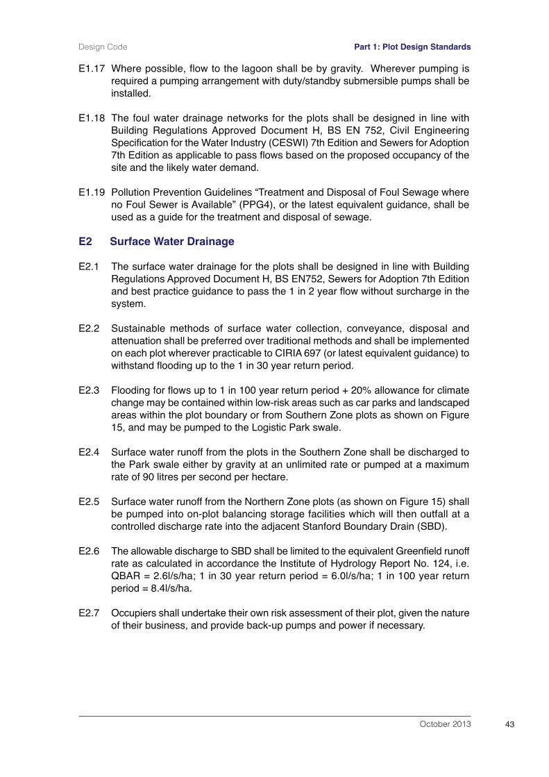
E2 Surface Water Drainage
E2.1 The surface water drainage for the plots shall be designed in line with BuildingRegulations Approved Document H, BS EN752, Sewers for Adoption 7th Editionand best practice guidance to pass the 1 in 2 year flow without surcharge in thesystem.
E2.2 Sustainable methods of surface water collection, conveyance, disposal andattenuation shall be preferred over traditional methods and shall be implementedon each plot wherever practicable to CIRIA 697 (or latest equivalent guidance) towithstand flooding up to the 1 in 30 year return period.
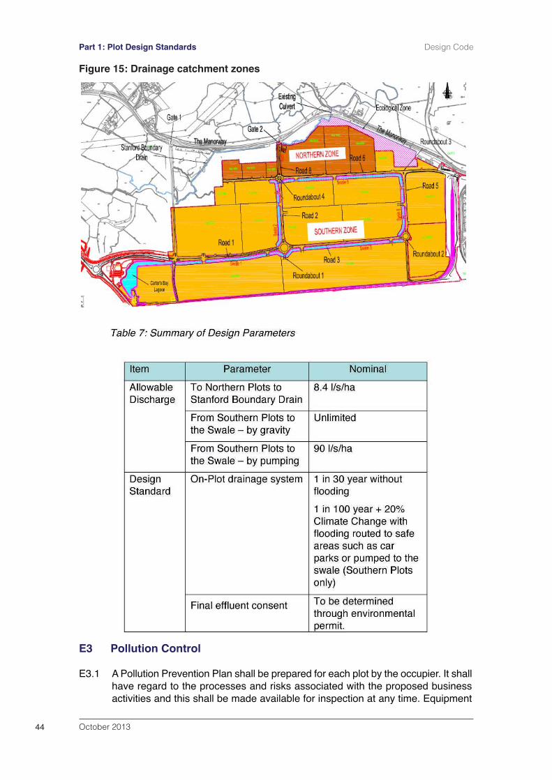
E2.3 Flooding for flows up to 1 in 100 year return period + 20% allowance for climatechange may be contained within low-risk areas such as car parks and landscapedareas within the plot boundary or from Southern Zone plots as shown on Figure15, and may be pumped to the Logistic Park swale.
E2.4 Surface water runoff from the plots in the Southern Zone shall be discharged tothe Park swale either by gravity at an unlimited rate or pumped at a maximumrate of 90 litres per second per hectare.
E2.5 Surface water runoff from the Northern Zone plots (as shown on Figure 15) shallbe pumped into on-plot balancing storage facilities which will then outfall at acontrolled discharge rate into the adjacent Stanford Boundary Drain (SBD).
E2.6 The allowable discharge to SBD shall be limited to the equivalent Greenfield runoffrate as calculated in accordance the Institute of Hydrology Report No. 124, i.e.QBAR = 2.6l/s/ha; 1 in 30 year return period = 6.0l/s/ha; 1 in 100 year returnperiod = 8.4l/s/ha.
E2.7 Occupiers shall undertake their own risk assessment of their plot, given the natureof their business, and provide back-up pumps and power if necessary.
October 2013 43
Design Code Part 1: Plot Design Standards
E3 Pollution Control
E3.1 A Pollution Prevention Plan shall be prepared for each plot by the occupier. It shallhave regard to the processes and risks associated with the proposed businessactivities and this shall be made available for inspection at any time. Equipment
October 201344
Part 1: Plot Design Standards Design Code
Figure 15: Drainage catchment zones
to contain spillages, including oil booms but also drain blockers and dams tocontain soluble pollutants shall be made readily available.
E3.2 The swales alongside plot access roads throughout the site shall be inspected,at least on a weekly basis, for signs of pollution, such as oil on the water surface.A programme of monitoring the water quality in the swales and the treatment plandischarges thereto shall be agreed with the Environment Agency prior tooccupation of the plots. Where pollution is evident, as with visible oil, appropriateclean-up measures, such as absorbent booms shall be used to remove it. Oilbooms shall be removed on completion of the clean-up to avoid re-release of oilor potential blockages.
E3.3 The drainage system from each plot shall require oil separators, grease traps andother containment at source, as necessary for the nature of each business.
E3.4 Any oil, fuel or chemical storage tanks, buildings, ancillary handling facilities,filling, drawing and overflow pipes shall be enclosed within an impervious bundedarea of at least 110% of the tank capacity and the bunded area shall be fullyconstructed in accordance with current Oil Storage Regulations before therelevant part of the development to which it first relates is first occupied or broughtinto use.
E3.5 Parking areas in excess of 50 spaces, and areas accessed by commercialvehicles or HGVʼs, shall be drained to the drainage network via an on-site oilseparator designed in accordance with Pollution Prevention Guidelines ʻUse andDesign of Oil Separatorsʼ (PPG3). Silt shall be managed at source.
E3.6 In the event of a major pollution incident occurring on-plot, the system shall beisolated or discharge to the swale shall be shut down until the pollution incidenthas been cleaned up.
E3.7 Plot drainage shall be separated from the main surface water drainage system atthe following locations to allow for the containment of pollutants:
Loading areas where spillage of cargo may occur;Skip/waste storage areas;Areas where chemicals and oils are stored;Boiler/chiller areas where condensates are discharged.
E3.8 On-plot vehicle fuelling point or lorry/car washing facilities shall be isolated andany surface water runoff shall be discharged to the foul drainage system, providedthe foul drainage system is designed to treat this, before discharging into theswale. Alternatively, this run-off shall be treated as trade effluent, and shall beisolated and taken off site for disposal at a licensed facility.
E3.9 Any effluent other than of a domestic nature shall be isolated, taken off site fordisposal or treated separately as appropriate.
E3.10 Surface water runoff from waste storage areas and any other high risk areas shallbe treated appropriately and discharged in accordance with relevant BuildingRegulations, PPG and SUDS guidance.
October 2013 45
Design Code Part 1: Plot Design Standards

October 201346
Part 1: Plot Design Standards Design Code

October 2013 47
Design Code Part 2: Infrastructure Standards
Part 2:Infrastructure Standards

October 201348
Part 2: Infrastructure Standards Design Code
October 2013 49
Design Code Part 2: Infrastructure Standards
PART 2: Infrastructure Standards
F Highway Design Standards
F1.0 The following highway design standards shall apply to the construction of internalsite access roads, footways and cycleways. Road infrastructure connections foreach phase of development shall be provided to wearing course prior tooperational use of any building.
F1 Internal Access Roads
F1.1 The general layout and hierarchy of the internal access roads is shown on Figure16.
F1.2 The primary and secondary infrastructure corridors shall be constructed toaccommodate the road carriageway, service corridors, verges (including a shareduse cycleway and footway) and landscaped drainage channel (swales) in stepwith the phased development of the site.
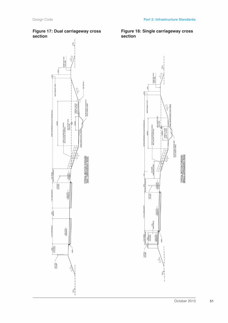
F1.3 Dual carriageways and single carriageway roads shall be constructed to thedimensional standards identified on the cross sectional drawings set out atFigures 17 and 18.
F1.4 All roads shall be constructed in accordance with requirements set out in theDesign Manual for Roads and Bridges (DMRB).
F1.5 Security fences or gates shall not obscure sight lines of any junction on the publichighway or any vehicular access to the highway.
F2 Road Drainage
F2.1 The carriageways in the Park shall be provided with infiltration drains to interceptsurface water runoff and allow it to soak into the fill and filter drains to interceptthe silt and minimise the requirement for periodic de-silting of the channel.
F2.2 The roundabouts shall be provided with a surface water drainage systemcomprising a combined drainage and kerb system as defined in HA39 of theDMRB. These shall be connected to the swale drainage system via deep trapgullies and a watertight carrier drain or gully tail.
F3 Pollution Control
F3.1 Equipment to contain spillages including oil booms, drain blockers and dams tocontain soluble pollutants, shall be made readily available by London GatewayPark Development Limited (LGPDL).
F3.2 Spillage containment facilities shall be provided at roundabouts and majorjunctions where an increased risk of vehicle collision/overturning exists. Slots forstop logs at the upstream end of the culverts shall be included within the designof the culverts.

October 201350
Part 2: Infrastructure Standards Design Code
Prim
ary
Dua
l
Prim
ary
Sin
gle
Sec
onda
ry S
ingl
e
Figure 16: Layout and hierarchy of internal access roads
October 2013 51
Design Code Part 2: Infrastructure Standards
Figure 17: Dual carriageway crosssection
Figure 18: Single carriageway crosssection
F4 Materials
F4.1 Materials for road construction shall be compliant with the appropriate BritishStandard or other relevant specification.
F4.2 Primary and secondary roads, roundabouts and development plot entrances shallbe predominantly asphalt.
F4.3 Standard profile concrete kerbs shall be used adjacent to footpaths / cycleways.High profile concrete kerbs shall be used at HGV entrances and HGV accessiblelocations.
F4.4 Road marking shall be in white or yellow thermoplastic paint and kerbs shall beused to provide protection to pedestrian areas.
F4.5 When available, suitably recycled, locally sourced or ʻgreen energyʼ materialsshall be used where these conform to the necessary standards and will meet thenecessary performance standards or specification.
Standards for Footpaths and Cycleways
F4.6 Footways/cycleways shall be a minimum of 3m width.
F4.7 Where footways/cycleways are liable to vehicle over-run, materials shall berestricted to:
Bituminous materials to DMRB standards unless there is a need to matchexisting paths surfaced with Hot Rolled Asphalt (HRA). Resin bound material - Highways Authorities Product Approval Scheme(HAPAS) certified with a minimum design life of 25 years.Where appropriate, concrete block paving, including tumbled blocks, 100mmx 200mm x 80mm.
F4.8 Where the footway will not be over run or otherwise damaged by vehicles thefollowing paving may be used in addition to that noted above.
400mm x 400mm x 65mm standard concrete paving slabs400mm x 400mm x 65mm textured concrete paving slabs.
F5 Bus routes and facilities
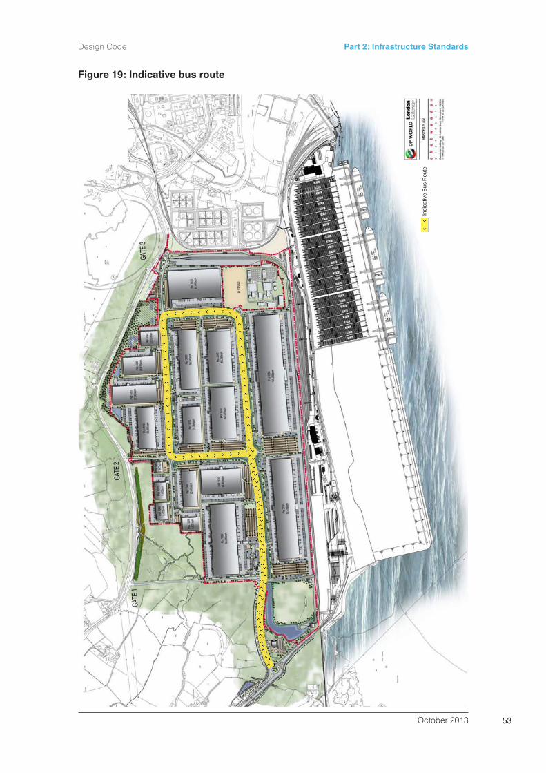
F5.1 An indicative bus route through the logistics park is shown on Figure 19. Raisedlevel bus stop kerbs shall be incorporated along the bus route to create a levelentry platform.
F5.2 A bus stop flag with timetable case shall be provided at all bus stops. Whereappropriate the flag shall be attached to other street furniture to minimise clutter,otherwise it shall be fitted to a proprietary bus stop pole. Bus stop pole, flags andtimetable cases shall be from the current range set out in the Essex CountyCouncil Street Materials Guide or any such subsequent guidance as may beproduced by Thurrock Council.
October 201352
Part 2: Infrastructure Standards Design Code
October 2013 53
Design Code Part 2: Infrastructure Standards
Indi
cativ
e B
us R
oute
Figure 19: Indicative bus route
F5.3 Where provided, bus shelters shall be metal framed in black to RAL 9005, with alow barrelled or vaulted roof. Shelters shall be fitted with end panels to provideprotection from the weather with a clear view panel on the bus approach side.Shelters shall be in accordance with the Accessible Bus Stop Design Guide (BusPriority Team technical advice note BP1/06 January 2006) prepared by Transportfor London (TFL) or the latest equivalent guidance.
F5.4 Bus shelters shall be fitted with bench seating with armrests, although perchseating may be installed if space is limited. All bus shelters shall be fitted withplates showing the bus stop name on the kerb face and at both ends and shallhave an information board installed.
F6 Soft landscaping
Infrastructure Corridors
F6.1 Landscaping aligning the infrastructure roads shall include a range of plantingtreatments created in linear sections not exceeding 80m in length.
F6.2 The central reservation of infrastructure roads shall be planted, alternatingbetween single species formal hedgerows and groundcover shrubs. Hedgerow /shrub planting sections shall not exceed 40m in length.
F6.3 Landscaping aligning the secondary infrastructure roads shall be predominantlynative and smaller in scale than that proposed on primary infrastructure roads.
F6.4 A native hedgerow shall be planted where 10m planted buffer strips on plots abutinfrastructure areas to establish a dense edge and deter access.
F6.5 Service corridors aligning infrastructure roads shall be grass seeded or turfed.
F6.6 The planting schemes shall take into consideration the required visibility for roadusers.
Roundabouts and Plot Entrances
F6.7 Specimen trees, ornamental shrub planting and formal hedgerows shall bepermitted at key nodes to provide interest.
F6.8 To assist users in wayfinding around the site, species at the approach toroundabouts shall be selected for their foliage or stem colour and shall beconsistent with that used at the nearest roundabout to the plot. This colour shallbe applicable as a theme for that roundabout and applied to any architectural orartistic features contained within it.
F7 Lighting Requirements
General Considerations
F7.1 The general standards set out for Plots at paragraphs B8.38 – B8.40 shall applyto all exterior lighting across the site. References to lighting equipment areindicative and may be amended subject to achieving the stated performancerequirements.
October 201354
Part 2: Infrastructure Standards Design Code
F7.2 Lighting equipment when installed, shall meet the lighting constraints defined inILP Guidance Notes GN01 for the control of obtrusive light for the EnvironmentalZone applicable to the location of the site (see Figure 6). Additional care shall betaken to minimise light spill and glare from any lighting installed by ensuring thecorrect luminaire is selected and installed in line with the recommendations withinCIE 150 (2003) and ILP GN01. The design shall ensure the mounting heightsemployed are the minimum necessary to achieve the lighting performancerequirements. Illuminance levels shall not exceed 1.0 lux at 25m from the Siteboundary and 0.1 lux at 50m from the Site boundary.
F7.3 Lighting columns shall have foundations suited to the ground conditions tomaintain lifetime stability and safety and may need to be piled.
Lighting Classes
F7.4 The lighting classes for roads footways and cycleways would be as set out in BS5489-1: 2013 Code of practice for the design of road lighting – Part 1: Lighting ofroads and public amenity areas or as subsequently modified and BS EN13201:2003 Road Lighting. The lighting classes for outdoor work areas wouldbe as set out in BS EN 12464-2:2007 Light and Lighting – Lighting of workplaces;Part 2: Outdoor work places.
Primary and Secondary Roads
Performance RequirementsF7.5 The lighting of the primary and secondary roads shall be designed to lighting class
ME3b of BS5489-1:2013. The performance requirements are:
Average luminance, Lav: 1.0cd/m²Overall Unifomity, Uo: 0.40 minimumLongitudinal Uniformity, Ul: 0.60 minimumThreshold Increment, TI: 15% maximum
F7.6 At roundabouts and junctions luminance performance criteria shall not apply andthese should be treated as Conflict Areas where CE class illuminance criteriashall apply.
F7.7 At junctions with primary or secondary roads, the lighting shall meet class CE2 ofBS 5489-1 as follows:
Average illuminance, Eav: 20 luxOverall Uniformity, Uo: 0.40 minimum
Equipment detailsLuminaire and lamp: Urbis Furyo 2 lantern or equivalent with 140W
CPO-TWLighting column and bracket: Urbis FLO column and bracket or equivalent of
10m maximum heightMounting attitude: Zero inclination
October 2013 55
Design Code Part 2: Infrastructure Standards

Installation GeometryF7.8 Dual Carriageway: Lighting columns shall be mounted in an opposite arrangement
at the rear of the services corridor or boundary of the services corridor andcycleway/footway at a nominal longitudinal spacing of 38m.
F7.9 Single Carriageway: Lighting columns shall be mounted in a single sidedarrangement at the rear of the cycleway/footway at a nominal longitudinal spacingof 36m.
Lighting for Formal Footways and Cycleways
F7.10 Where there is a footway or cycleway alongside the carriageway, the SurroundRatio of the luminaires installed for the carriageway lighting shall provide sufficientlighting of the footway and cycleway without the need for supplementary lighting.
F7.11 Where footways are remote from other lit areas dedicated lighting shall beprovided to lighting class S4 of BS 5489-1.
Performance RequirementsF7.12 The performance requirement for lighting class S4 is:
Average illuminance, Eav: 5 to 7.5 luxMinimum illuminance, Emin: 1.0 lux
F7.13 This level can be further reduced dependent upon the Ra and the S/P ratio of thelamp in accordance with Clause A 3.3.3 of BS5489-1:2013.
Equipment DetailsLuminaire and lamp: Urbis Furyo 1 lantern or equivalent with 45W
CPO-TWLighting column and bracket: Raising and lowering column and 0.5m bracket
of 5m maximum height.Mounting attitude: Zero inclination
Installation GeometryF7.14 Single Carriageway: Lighting columns shall be mounted in a single sided
arrangement at the rear of the cycleway/footway at a nominal longitudinal spacingof 30m.
Lighting for Bus Stops
F7.15 Lighting columns shall be positioned so as not to obstruct bus doors and shall belocated outside the boarding/alighting zone. An enhanced level of street lightingshall not be necessary at bus stops.
F7.16 Electrical supply for bus shelter lighting and communications shall not originatefrom the street lighting supplies.
F8 Signage
F8.1 Estate signage shall accord with Traffic Signs Regulations and General Directions1981 (or any revisions thereto) to maintain a coordinated appearance to thedevelopment.
October 201356
Part 2: Infrastructure Standards Design Code

F9 Emergency Access
F9.1 Gates 1 and 3 shall be utilised to provide an alternative access route foremergency vehicles and buses. These routes shall comprise a minimum of singlelane roadways of 3.7m width with locked gates to the perimeter of the site.
F9.2 Access requirements for fire and rescue vehicles shall comply with Part B, Section16 of the Building Regulations (Volume 2, 2006 Edition, Amended 2007 and2010).
October 2013 57
Design Code Part 2: Infrastructure Standards
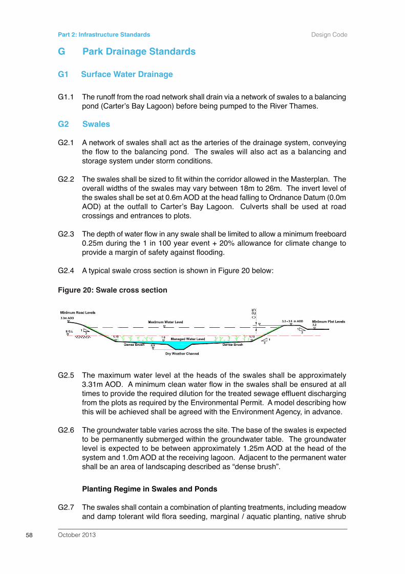
G Park Drainage Standards
G1 Surface Water Drainage
G1.1 The runoff from the road network shall drain via a network of swales to a balancingpond (Carterʼs Bay Lagoon) before being pumped to the River Thames.
G2 Swales
G2.1 A network of swales shall act as the arteries of the drainage system, conveyingthe flow to the balancing pond. The swales will also act as a balancing andstorage system under storm conditions.
G2.2 The swales shall be sized to fit within the corridor allowed in the Masterplan. Theoverall widths of the swales may vary between 18m to 26m. The invert level ofthe swales shall be set at 0.6m AOD at the head falling to Ordnance Datum (0.0mAOD) at the outfall to Carterʼs Bay Lagoon. Culverts shall be used at roadcrossings and entrances to plots.
G2.3 The depth of water flow in any swale shall be limited to allow a minimum freeboard0.25m during the 1 in 100 year event + 20% allowance for climate change toprovide a margin of safety against flooding.
G2.4 A typical swale cross section is shown in Figure 20 below:
G2.5 The maximum water level at the heads of the swales shall be approximately3.31m AOD. A minimum clean water flow in the swales shall be ensured at alltimes to provide the required dilution for the treated sewage effluent dischargingfrom the plots as required by the Environmental Permit. A model describing howthis will be achieved shall be agreed with the Environment Agency, in advance.
G2.6 The groundwater table varies across the site. The base of the swales is expectedto be permanently submerged within the groundwater table. The groundwaterlevel is expected to be between approximately 1.25m AOD at the head of thesystem and 1.0m AOD at the receiving lagoon. Adjacent to the permanent watershall be an area of landscaping described as “dense brush”.
Planting Regime in Swales and Ponds
G2.7 The swales shall contain a combination of planting treatments, including meadowand damp tolerant wild flora seeding, marginal / aquatic planting, native shrub
October 201358
Part 2: Infrastructure Standards Design Code
Figure 20: Swale cross section
planting and standard tree planting. Variation shall be achieved along their lengththrough the use of differing plant species.
G2.8 The composition of the wildflower seed mix shall include species that are able tothrive in drier conditions at the upper margins of wetlands and damp tolerantvarieties capable of establishing on the lower slopes.
G2.9 Species selection for marginal plants shall be robust and able to cope withchanges in water level. Over time there shall be a subtle adaptation in the plantingscheme in response to fluctuations in water level and management techniques.
G2.10 Hedgerows and shrub planting shall be provided along the swale corridor (seeFigure 21) to provide low level screening and to discourage public access to theswales and guide movement. Timber knee rails shall be installed as a guide topedestrians where planting is not otherwise present.
G2.11 Drainage swales aligning the infrastructure roads shall include a range of nativeplanting treatments along their length. Whilst narrower than those adjacent to theprimary infrastructure roads, drainage swales on secondary roads shall stillinclude a range of planting treatments.
G2.12 Steps shall be incorporated into drainage swales to allow access for maintenanceand safety. Slopes within swales and water bodies shall not exceed a maximumgradient of 1:3.
G2.13 For safety, where stepped access is not otherwise provided, water bodies shallbe designed to accommodate areas where the maximum gradient does notexceed a slope of 1:5.
G3 Carterʼs Bay Lagoon
G3.1 The swale network shall drain to a 3.1ha attenuation pond named Carterʼs BayLagoon. This may be constructed in two phases in line with developmentrequirements.
G3.2 The effective depth above the baseflow level shall be maintained for storm flowsby pumping down to the permanent water level in the Carterʼs Bay Lagoon. Pumpcontrols shall be set to maintain the level in the lagoon / swales to approximately1.0m AOD during dry weather flow. The invert level of the lagoon shall be set atOrdnance Datum (0.0 m AOD).
G3.3 The lagoon shall have a side slope of 1 in 3. A safety ledge / berm ofapproximately 5m width shall be provided around the wet area of the lagoon formaintenance.
G3.4 The lagoon shall be provided with safety features as detailed in CIRIA Guide C697or the latest equivalent guidance. As a minimum, stepped egress points anddanger warning signs incorporating buoyancy aids shall be provided atappropriate intervals.
G3.5 Provision shall be made to facilitate the emptying of the lagoon using the pumpingstation.
October 2013 59
Design Code Part 2: Infrastructure Standards
G3.6 A typical plan and cross-section of the lagoon is shown on Figure 22.
G3.7 Summary of Carterʼs Bay Lagoon detail is as follows:
Surface Area: 3.1 haBank Level: 3.2 m AODInvert Level: 0 to -0.3m AOD (Inlet to Outlet)Permanent Water Level 1.0m AODBerm width above permanent water: 5m
Planting and Ecological Requirements
G3.8 Carterʼs Bay Lagoon shall contain a combination of planting treatments includingblocks of trees and shrub planting, wildflora grassland and marginal aquaticspecies (see Figure 23).
G3.9 To provide safe high-tide roosting habitat for Ringed Plover, anchored floatingshingle rafts shall be provided within the lagoon. The total site area of the shinglerafts shall be 500sq.m, with a minimum sized raft of 100sq.m, a minimum shinglesubstrate depth of 100mm and 150mm high perimeter lip.
G3.10 The profile of the lagoon shall be terraced to enable public access and formaintenance. Slopes shall not exceed a maximum gradient of 1: 3 but shall beappropriate to aid establishment of planting.
G3.11 Shallow shelves shall be incorporated into the lower margins of wetlands, to aidestablishment of marginal and aquatic species. Species selection for marginalplants shall be robust and able to cope with changes in water level.
G3.12 The composition of the wildflower seed mix shall include species that are able tothrive in drier conditions at the upper margins and damp tolerant varieties capableof establishing on the lower slopes.
G3.13 Planting surrounding Carterʼs Lagoon shall assist in screening views towards thepumping station from the surrounding area and in providing an attractive settingfor those employed within the area to walk around.
G3.14 The raised embankment shall be tied back into the adjacent land at a gradientnot exceeding 1:3 and be seeded with wildflowers.
G4 The Pumping Station and Outfall Arrangement
G4.1 The pumping station at the southern end of the Carterʼs Bay Lagoon shall lift thesurface water runoff from Carterʼs Bay Lagoon to the Thames.
G4.2 A pumping rate to the Thames of no more than 2m3/s will ensure the water levelin the swales does not exceed the maximum permitted and will reduce the waterlevel in the balancing lagoon in good time to provide capacity for subsequentstorms.
G4.3 Construction of the pumping station shall be phased to meet the drainagerequirement of the Park. As the site is developed additional pumps andassociated equipment shall be installed.
October 201360
Part 2: Infrastructure Standards Design Code
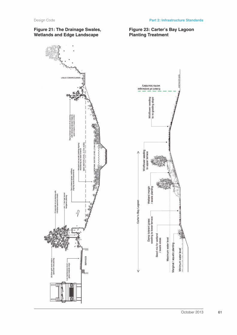
October 2013 61
Design Code Part 2: Infrastructure Standards
Figure 21: The Drainage Swales,Wetlands and Edge Landscape
Figure 23: Carterʼs Bay LagoonPlanting Treatment
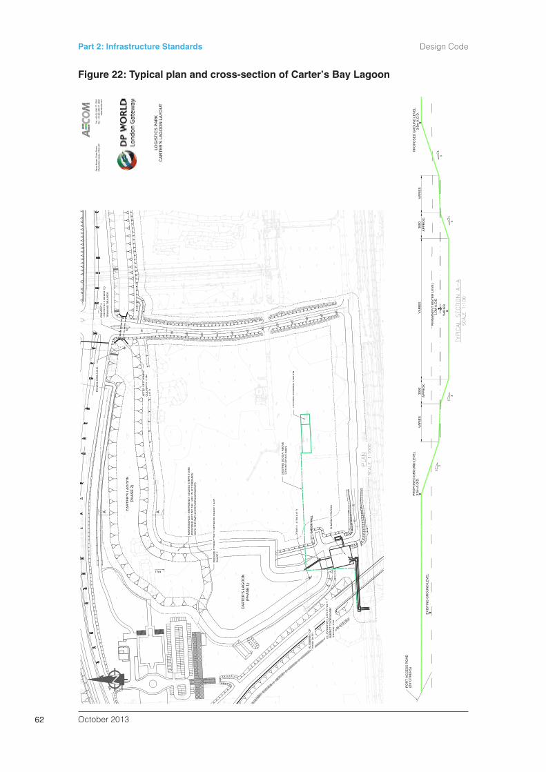
October 201362
Part 2: Infrastructure Standards Design Code
1111
22
2222242440404444000044
220220
44
22222222222222222222222222222222222222
44444444444444
22220220
240240222402404400
22222222222220202220202222222222222222222222
44444444444444444444444444444444
28280000
0000000026266626262626
80800080808080
00660066666666666666
00888800000000000000000000
00000022260260
00808022280280
66666666666666666666666666666666
888888888888888888888880800000
00000000
000022002222002222222222222222222222222222222222222222
440000444040
000066
0088380380
44224204204422420420
00440440
44460460
480480
55
11120120
11140140
11160160
11180180
A
00
PO
22520520
540540
ND
IL0.
0MA
.O.D
.D
IL0
0MA
O
00560560
580580
00
202020202020202022202000620620
DR
AW
ING
DR
A-0
505
RA
WIN
FOR
DE
TAIL
S R
EFE
R T
LS R
EC
ULV
ER
T 4
6600000066
00006666
6666
00000000000000000000000000
680680
66666666000000
66444444000000 TO
720720
680680
4040740740
Che
lmsf
ord,
ES
axon
Hou
seE
ssex
, CM
1 1H
Te,
Duk
e S
treet
,
ww
w.a
ecom
.com
Fax:
+44
(0) 1
245
77 1
299
Tel:
+44
(0) 1
245
77 1
200
(PH
AS
E 2
(PH
AC
AR
TER
'S L
AG
AG )G
OO
GO
ON
A.O
.D.
.OD
CU
LVE
AFT
ER E
RT
IL0.
0MT
IL0
R S
ETT
LEM
EN
TM
EN
T
20 40
LOG
ISTI
CS
PA
RK
spa
8 sp
aces
FALL ALL
A
00
60 80 100
CCA
RTE
R'S
LA
GO
OLO
GIS
TIC
S O
N L
AY
OU
TP
AR
K
PH
AS
E 2 2
PR
OV
IDE
WIT
H T
HE
EM
H T
HE
EM
PR
OV
IDE
D A
MA
INTE
NA
NC
EC
ON
NE
CTI
VIT
YB
ETW
EE
EEM
PLO
YE
R'S
RE
QU
IRE
ME
NM
PA
RO
UN
D T
HE
LA
KE
IN A
CC
HE
LA
KE
IC
E /
EM
ER
GE
NC
Y A
CC
ES
S
NP
HA
SE
1A
ND
NP
HA
SE
1A
NTSS
TEP
STO
CO
RD
AN
CE
SS
TEP
STO
BE
000100
120
140
(PH
AS
E 1
(PH
AC
AR
TER
'S L
AG
AG )G
OO
GO
ON
1160
180
GR
OU
ND
RIS
ING
DR
EX
ISTI
NG
300
DIA
MA
INA
.AB
OV
A. A
BO
VE
000202200
220
PO
ND
FIX
ED
ON
DA
LIG
NM
EN
T O
FN
T O
PO
ND
IL-0
.3M
IL-0
3MMA
.O.D
.M
A
GR
OU
ND
RIS
ING
OU
ND
MA
IN
EX
ISTI
NG
PU
MP
NG
PU
MPP
ING
STA
TIO
NP
ING
ST
040
024
260
CO
NTR
AC
TOR
ON
TRA
SU
BJE
CT
TO D
ES
O D
ES
ILLU
STR
ATI
VE
LA S
IGN
BY
SAY
OU
T O
NLY
T O
NL
PU
MP
ING
NGG
STA
TIO
NG
STA
TIO
N
0280
300
4040
02020
(BY
P
OR O
THE
RS
)R
T A
CC
ES
S R
OA
D
35
AP
RO
PO A
OD
OS
ED
GR
OU
ND
LE
VE
LP
RO
PO
SE
D G
RO
OO
UN
D L
EV
EL
EX
ISTI
NG
GR
OU
ND
LE
VE
L
3.5m
AA.O
.D.
31
VA
RI
1
AP
PR
O30
00IE
SO
X.
0
PE
PE
PE
PE
VA
RIE
S
ER
MN
N
VA
RIE
SV
AR
IES
VA
RIE
S
1.0M
A.O
.D1.
0M A
.O.D
ER
MA
NE
NT
WA
TER
LEE
RM
AN
EN
TW
ATE
RLE
ER
MA
NE
NT
WA
TER
LEE
EEEV
EL
AP
PR
300
1
RO
X.
00V
AR
IIES
31
3.55m
A.O
.D.
31
31
Figure 22: Typical plan and cross-section of Carterʼs Bay Lagoon
G4.4 The two outfall pipes shall be extended up to the new pumping station and beused as rising mains to allow the discharge of surface water from the lagoon tothe Thames. The rising mains shall be approximately 130m long.
G4.5 A minimum pumping rate to the tidal estuary to be defined in the model agreedwith the Environment Agency (see paragraph G2.5) shall be maintained sufficientto maintain a low flow within the swale system without excessive drawdown ofgroundwater local to the swales.
G4.6 One of the existing outfall pipes may be used for gravity drainage to allow thedraining of the lagoon by gravity down to 1.0m AOD when the water level in thelagoon is above the tide level.
G4.7 LGPDL shall monitor the outfall for signs of scour. In the event that scour isoccurring appropriate action shall be taken to minimise its effect. This may includethe construction of concrete or stone blocks/teeth onto the outfall apron.
Standby Generator
G4.8 Two additional standby pumps shall be provided in the pump station.
G4.9 A standby generator shall be installed adjacent to the pumping station. Thestandby generator shall be required when approximately 70% of the site isoccupied.
G5 Pollution Control
G5.1 Equipment to contain spillages, including oil booms but also drain blockers anddams to contain soluble pollutants shall be made readily available by LGPDL. A“long-stop” containment facility shall be provided at Carterʼs Bay Lagoon.
G5.2 Slots for stop logs at the upstream end of the culverts carrying the swales beneathPark roads and plot accesses shall be included within the design of culverts.
G5.3 The swale / attenuation pond drainage systems may be provided with plantingand reed beds that promote treatment, where feasible to do so, withoutcompromising their primary purpose of conveying water to the pumping stations.
G6 Operation and Maintenance
G6.1 Trash screens shall only be required at the inlet channels to the pumping station.Debris shall be mechanically removed and the bar spacing sized to avoid debrisfrom damaging the pumps. Provision shall be made at the pumping station intake,for example with a scum board, to prevent floating debris and oil from enteringthe pumping station and being discharged into the estuary.
G6.2 The swale shall be maintained through a simple regime of occasional grasscutting, annual clearance of more excessive vegetation and major clearance /reshaping every 5 to 10 years.
October 2013 63
Design Code Part 2: Infrastructure Standards
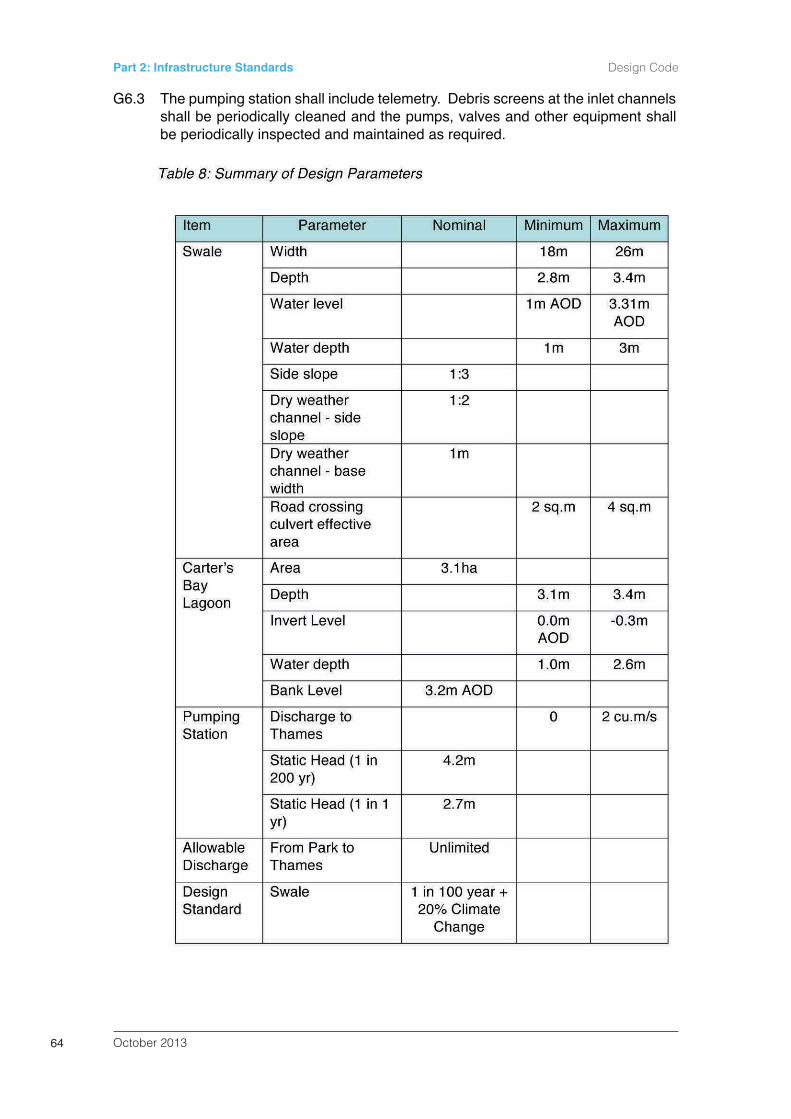
G6.3 The pumping station shall include telemetry. Debris screens at the inlet channelsshall be periodically cleaned and the pumps, valves and other equipment shallbe periodically inspected and maintained as required.
October 201364
Part 2: Infrastructure Standards Design Code
H Land Raising
H1 Land Raising
H1.1 Earth re-profiling shall raise the site to the levels set out in Section D of the CoCP.The raised site shall be tied into the existing landform along its edge at a gradientnot exceeding 1:3.
H1.2 The fill material for land raising shall meet the requirements of the EnvironmentalPermit (Reference EPRIYP3691 EK/A001).
October 2013 65
Design Code Part 2: Infrastructure Standards
I General Landscaping Requirements
I1 Soft Landscape Specification
I1.1 Native shrub, woodland planting and areas of mown and wildflower grasslandshall predominate unless otherwise described in this Design Code.
I1.2 Plant species in general will include (but will not necessarily be restricted to) thoselisted within Appendix 1.
I2 Strategic Landscaping Framework
Edge of Site
I2.1 Re-graded slopes to plots shall be aligned along their upper edge by standardtrees in a native hedgerow. Understorey and woodland planting will also beestablished on a minimum of 50% of the remaining slope area.
Strategic Landscaping North
I2.2 Strategic landscaping to the north of the site shall be in accordance with theStructural Landscape Plans included at Appendix 3.
Strategic Landscaping West
I2.3 A strategic landscaping scheme shall be provided along the western edge of thePark to reduce disturbance to wintering birds in accordance with the landscapeplans shown at Appendix 4. The landscaping shall incorporate a native mixʻInstant Hedgeʼ and a 1.2m high timber screen fencing planted on top of a 1mmound (above adjacent plot levels) to the west of the Gate 1 access road,Understorey and woodland planting shall be established on a minimum 50% onthe regraded slope at the Site edge.
I2.4 A 10m strip of strategic planting shall be provided along the western most plotboundary in accordance with paragraphs C4.4.
I3 Street Furniture, Boundary Treatments & Feature Elements
I3.1 Street furniture and boundary features within infrastructure corridors shall beselected to provide visual interest to the scheme and respond to the individualneeds of each development phase.
I3.2 Street furniture (i.e. seating, cycle storage) shall be grouped together and locatedin close proximity to key building entrances.
I3.3 Street furniture products shall be applied in families which are complementary toone another.
October 201366
Part 2: Infrastructure Standards Design Code
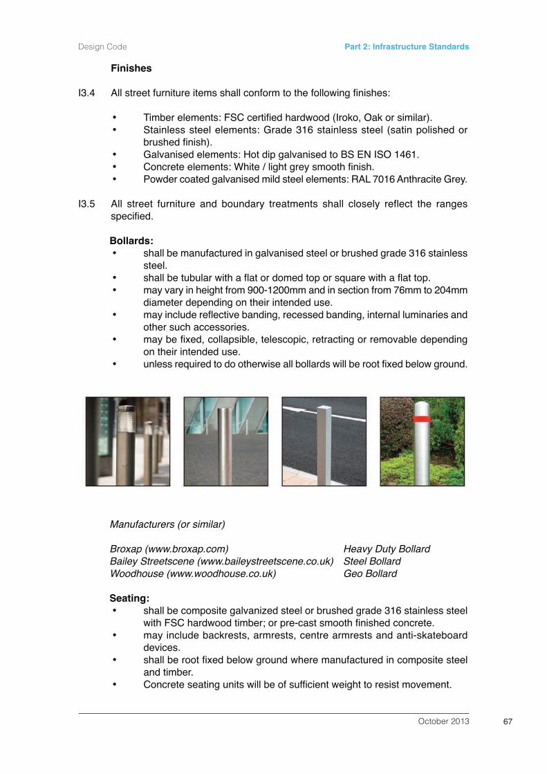
Finishes
I3.4 All street furniture items shall conform to the following finishes:
Timber elements: FSC certified hardwood (Iroko, Oak or similar).Stainless steel elements: Grade 316 stainless steel (satin polished orbrushed finish).Galvanised elements: Hot dip galvanised to BS EN ISO 1461.Concrete elements: White / light grey smooth finish.Powder coated galvanised mild steel elements: RAL 7016 Anthracite Grey.
I3.5 All street furniture and boundary treatments shall closely reflect the rangesspecified.
Bollards:shall be manufactured in galvanised steel or brushed grade 316 stainlesssteel.shall be tubular with a flat or domed top or square with a flat top.may vary in height from 900-1200mm and in section from 76mm to 204mmdiameter depending on their intended use.may include reflective banding, recessed banding, internal luminaries andother such accessories.may be fixed, collapsible, telescopic, retracting or removable dependingon their intended use.unless required to do otherwise all bollards will be root fixed below ground.
Manufacturers (or similar)
Broxap (www.broxap.com) Heavy Duty BollardBailey Streetscene (www.baileystreetscene.co.uk) Steel BollardWoodhouse (www.woodhouse.co.uk) Geo Bollard
Seating:shall be composite galvanized steel or brushed grade 316 stainless steelwith FSC hardwood timber; or pre-cast smooth finished concrete. may include backrests, armrests, centre armrests and anti-skateboarddevices.shall be root fixed below ground where manufactured in composite steeland timber.Concrete seating units will be of sufficient weight to resist movement.
October 2013 67
Design Code Part 2: Infrastructure Standards
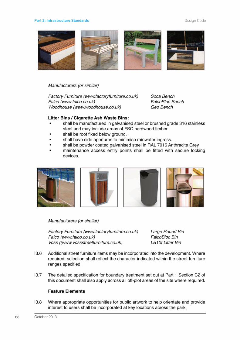
Manufacturers (or similar)
Factory Furniture (www.factoryfurniture.co.uk) Soca BenchFalco (www.falco.co.uk) FalcoBloc BenchWoodhouse (www.woodhouse.co.uk) Geo Bench
Litter Bins / Cigarette Ash Waste Bins:shall be manufactured in galvanised steel or brushed grade 316 stainlesssteel and may include areas of FSC hardwood timber.shall be root fixed below ground.shall have side apertures to minimise rainwater ingress.shall be powder coated galvanised steel in RAL 7016 Anthracite Greymaintenance access entry points shall be fitted with secure lockingdevices.
Manufacturers (or similar)
Factory Furniture (www.factoryfurniture.co.uk) Large Round BinFalco (www.falco.co.uk) FalcoBloc BinVoss ((www.vossstreetfurniture.co.uk) LB10t Litter Bin
I3.6 Additional street furniture items may be incorporated into the development. Whererequired, selection shall reflect the character indicated within the street furnitureranges specified.
I3.7 The detailed specification for boundary treatment set out at Part 1 Section C2 ofthis document shall also apply across all off-plot areas of the site where required.
Feature Elements
I3.8 Where appropriate opportunities for public artwork to help orientate and provideinterest to users shall be incorporated at key locations across the park.
October 201368
Part 2: Infrastructure Standards Design Code
I3.9 Lighting of landscaped areas for aesthetic effect may be provided in accordancewith the product specification set out at Part 1 Section C3.
I4 Landscape Management Plan
I4.1 A coherent, strategic and integrated approach to the management andmaintenance of the soft landscape components associated with the developmentshall be adopted in accordance with the Landscape Management Plan set out atAppendix 2 to ensure the successful establishment of vegetation and overallintegration works within the surrounding landscape.
October 2013 69
Design Code Part 2: Infrastructure Standards
J Service Infrastructure
J1.0 Service infrastructure upgrades to serve the development shall be required.
J1 Gas Supply
J1.1 The existing Mains (high/intermediate/medium pressures) run parallel to theManorway on the northern edge of the site. The new gas main shall connect tothis supply and shall be routed through to Gate 2 where it shall run in parallel withthe proposed central access road to individual plot gas governor/governor metersthroughout the Park.
J2 Potable and Non-Potable Water Supply
J2.1 Potable water supply shall be drawn from the existing Essex and Suffolk networkand shall be routed throughout the Park via Gates 1 and 2.
J2.2 Measures to reduce potable water consumption shall be implemented wherepracticable following an appropriate feasibility study. Non-potable water shall beused for landscape maintenance wherever possible through the re-use andrecycling of rainwater, the import of treated effluent from nearby wastewatertreatment facilities or abstraction from shallow groundwater and/or drainageswales on site, taking account of site constraints and license requirements.Abstractions from controlled water including groundwater shall be undertakenonly following due process and permitting under the Water Resources Act.
J3 Electricity Supply
J3.1 An 11kV distribution network shall be installed across the site to serve individualplot requirements. Secondary substations shall be installed on individual plots.The 11kV distribution network shall be fed from two 33kV/11kV primarysubstations, which are fed from the 33kV switching station.
J3.2 A number of new primary sub stations shall be located within the Park.
J4 Telecommunications
J4.1 The new fibre optic and traditional copper lines required shall branch off from thesurrounding BT network. In addition a new fibre optic network shall be providedfor Virgin Media Telecommunications. These currently run from The Manorwayroundabout to Coryton roundabout parallel with the south side of the road andfollow existing cabling through Gate 1 and 3 and along the existing access road.
J4.2 A private fibre optic network shall be installed to support communications ofvarious items such as CCTV, WLAN, BMS, ANPR and access control systems.This shall be accommodated in the infrastructure service corridors.
J5 Fire fighting systems
J5.1 Fire hydrants, sprinkler mains and sprinkler storage tanks shall be appropriatelysited, as required.
October 201370
Part 2: Infrastructure Standards Design Code
J6 Utility Infrastructure
J6.1 Inspection and access chambers, junction boxes, cabinets and feeder pillars shallbe located where they will not affect highway safety, cause unreasonableinconvenience to any user of the road network, or detract from the character ofthe street.
J6.2 Utility infrastructure shall usually be accommodated within the main infrastructurecorridors (within 2m of ground level) and within road verges or footpaths.
J6.3 Alternative routes or variations to the corridor dimension shall be consideredwhere appropriate to meet the specific requirements of a development. To ensurethat all parties are agreeable to such alternatives or variations, the developer shallobtain the written agreement of each individual service provider and any otherparty who would be affected.
J7 Sub-stations, Pumping Houses and Other Non-commercial Buildings.
J7.1 Sub-stations, pumping houses and other non-commercial buildings shall beconstructed to the material specification set out in Part 1 at Section A4.8.
October 2013 71
Design Code Part 2: Infrastructure Standards

October 201372
Part 2: Infrastructure Standards Design Code

Appendix 1:Soft Landscape Palette