.London Avenue· Cartal-.· 1nierim· Floodwalls . and
79
--- ---------- -------0----.-,-. --c-----_ ---.- ------------------------- ... _-----_ .. - ........ ----_. -'-' -_.,---;----'-----:-;- _.- . t. " ... .London Avenue· Cartal-.· 1nierim· o Floodwalls . and Levees- Revised General Design Memorandum prepared for _the . .. Co fuJriirsiti ners ".'-.' . . - >', lhe' Orle-ans 'Levee District No. 2049-0269 ' "'hoT .' "."'J. ,- '.' .. , .. - . .' ",. '. .-;7,: ". .
Transcript of .London Avenue· Cartal-.· 1nierim· Floodwalls . and
-,--:----=-c~ --- ---------- -------0----.-,-. ~-_=_:-~--~--. --c-----_ ---.- -------------------------... _-----_ .. - -~-----........ ----_. -'-' -_.,---;----'-----:-;- _.-
. .~.
t. "
... ~
.London Avenue· Cartal-.· 1nierim·o Floodwalls . and
Levees-Revised General Design Memorandum
prepared for _the
~{"}T<~7~ . ·.BQ.t;d'·~fLevee .. Co fuJriirsiti ners ".'-.' . . - >', -',\:-~-:'~,,: :~·,.:":of lhe' Orle-ans 'Levee District
,~,:}--: ~"",<qrl~ansLevee 'BoardContr~d No. 2049-0269 '
"'hoT .' "."'J. ~
,- '.'
.. , .. '~
-. .' ",.
'. .-;7,: ". ~ .

London AvenuJe~ftal:e\\ Interim 'Floodw\t~ s"\>\~ndLi;~'i:/l:
. . 'L"evees ~~e. E:!~)i .(/>i 3uAfI r'
'5J4
r:rl1 '~i..{. .;o;.f '..,'
S-1 ~. ·i
I-Ii . __ __ I-IT
. V u. ;--'\;:}
Revised General Design Memorandum
I ge . j
IT :;:::; . ------IIT-92.- -- ----.------ -----;~~1'_-
duT 91s1Q
.. ---:-...... --' ..
., ~ .. '
by
.. ,. . ","'''; ~l i"-. !~H:L~1;jJcla t? s Burk and AssO.~i~ies,' ';)ln~f~i~~}l;
Engineers· Architects· Plannerso~~~~lfuiental Scientists
~: .-
Mayl99C
. " .'" :b::.i<. .
~ - ' .. -. _ ... ' ....... -.. -

:'.:
London Avenue Canal Floodwalls and
L~vees
General Design Memorandum ~. J1 '\ .ono~:~{ " [19:JfiI ·~r··
Table of Contents . . ","
. PAGE NO. SECTION I - INTRODUCTION
Executive Summary ·:.:i"r~~!I. I-I Construction Phasing 1-2 The Corps of Engineers Plan 1-3 Cost Determination 1-3 Table 1-1, Summary of Proposed Improvements, Phase I 1-4
------'f-able-I-2,Summaryof-Proposed -Improvements,Phase-U -----_. -··--1-5---Table 1-3, Summary of Proposed Improvements, Phase ill 1-6 Plate 1-1, Construction Phasing
SECTION II - HYDRAULICS
General Procedures and Data
.. Results and Conclusions
IT-I IT-I IT-2
.::;;::",~:c;:~~~:,=-c,,~:::;:::c~~~~~~~.£~~~~~-g: . ___ ~.::_~~;:;,:.;'~=='s±:~:;;~:;=_ -:.:'.:""""=- - .------- :.... ate -, rOJect tage requency~ urves~----.-- •• ~.-)
Plate IT-3, Approximated Backwater':~4filesi' " '.'··cl!t· ~.
Plate IT-4, Pump Station Capacity C;~~ .:.v">·-::. Plate IT-5, Hydraulic Profile Elevations Plate IT-6, Project Hydraulic Profiles
Burk and Associates, Inc. 8407
'. '.:~ .
Pagei
",'-.:: "

London Avenue Canal Table of Contents (Continued)'
SECTION III .. EXISTING CONDmONS
General ProcedureS Existing Levees and Floodwalls Drainage Pumping Stations Bridges
m·l ill-I ill·l ill-2' ID·i··
"··f Results of Evaluation Real Estate
m·3 m'A J ~ ?"
Table ill-I, Summary of Existing Flood Protection Levees Plate ill-I, Existing Conditions
m·s . ".' .. J,;
Plate m-2, Tabulated Existing Conditions Plate ID-3, Existing Sheet Pile Data Plate ID-4, Existing Structures and Levels of Protection
SECTION IV - PROPOSED IMPROVEMENTS . ~>
General> .( IV-I /.
Earthen Levees IV·2 . -----SteerSlieefPilel:Walls-.----.--- . .. J. ... u--'-'IV:2,c--
Floodproofing of Crossings ~~3 Southern Railroad Bridge !tl3 Benefit Street Bridge r\rl4 Gentilly Boulevard Bridge IWS Mirabeau Avenue Bridge !V+'6
.(
Filmore Avenue Bridge I~7 Robert E. Lee Boulevard Bridge---·-- ~-g' .. ----Leon C. Simon Boulevard Bridge tv .. 9 Drainage Pumping Stations IV-10
=-···'·==., .. == .... tTfE~· .=.=-.-.. ~., ... =-, •... = .. · .... ···-,·,·~·,~==·~."="'·~~RiHe·gMlk1lt~·o"'fF~siderations·~·· .. ·::;;"'.."~:. .. ··::;.~;;:'~"""""'~~ ... ~"'.:~;C"n' .. ,--....:.:-'-~::'.::~:;;!f=:'.~::.~~c .. ::.~~-.'·"==~:=~···'·-=~=-=UtilitYRe~--·- .. ::·:~:c_~= •. ,="'. ___ _
Construction Priority IV -13 Table IV-I, Bridge Opening and Improvement IV-iS Table IV-2, Utility Relocation Schedule IV-16 Plate IV-I, Proposed Floodwalls and Levees, West Side Plate IV-2, Proposed Floodwalls and Levees, East Side Plate IV-3, Summary of Proposed Improvements, West Side
and Crossings . Plate IV -4, Summary of Proposed Improvements, East Side
and Phase ID Phase IV-5, Typical Levee Sections, Sta. 120+00 to Sta. 152+50,
West Side Plate IV-6, Typical Levee Sections, Sta. 152 +50 to Lake, West Side Plate IV-7, Typical Levee Sections, Sta. 127+00 to Lake, East Side
Burk and Associates, Inc. 8407 Page ii

London Avenue Canal Table of Contents (Continued)
Plate IV-8, Typical Sections, Sheet Pile I-Walls Plate IV-9, Existing Bridges, Typical Sections Plate IV-IO, Railroad Crossing, Gate Details· Plate IV-11, Bridge Modification (Alternate 1), Typical Details Plate IV-12, New Bridge (Alternate 2), Typical Details Plate IV-13, Flood Gate (Alternate 3), Gate Details Plate IV-14, DPS No.3, Site Plan Plate IV-IS, DPS No.3, Typical Sections Plate IV-16, DPS No.4, Site Plan Plate IV-17, DPS No.4, Typical Sections
APPENDIX A - PLAN PROFILE PLATES
General
Plate A-I through Plate A-7, West Side Plan and Profiles
Plate A-8 through Plate A-13, East Side Plan and Profiles
APPENDIX B - GEOTECHNICAL INVESTIGATIONS
General
Burk and Associates, Inc. 8407
PAGE NO.
A-I
B-1
Page iii

,. -' -" ... _-------
Executive Summary
SECTION I INTRODUCTION
In February of 1985, the U. S. Army Corps of Engineers officially decided to abandon the proposed Barrier Plan for hurricane protection in favor of the High Level Plan for hurricane protection to Lake Pontchartrain and vicinity. With this change in mind, the Orleans Levee Board, under its own initiative, implemented an interim flood protection plan which would be consistent with the U. S. Army Corps of Engineers plan.
In April 1986, a general design memorandum was prepared for this flood protection (protection for a 300 year storm plus two feet of free board with the Corps' current geotechnical design standards) which indicated a cost of 44 million dollars. At the time, the available budget for London Avenue Canal was considerably less than this amount. Therefore, the Board decided to upgrade tEen eXistm-g-sysTem-for inteririillood- protection tc,-a:lever Witrun-tlie'-budgetary limits. Also, with_ th~!20!ps =S1and;g'.~ "bei~_~ stringent, the Boa . ed to f?llo~Jh~ SCE's state of the art geotechnical critena an,
dards for -structural desi . .
As a result, this flood protection system was designed for a 100 year storm water elevation plus two feet of freeboard and with geotechnical standards established for this project. The-hydraulic curves and design were prepared by-the C.O.E. using their stage water elevations for different storms and pump discharge capacities derived from Sewerage and Water BOard's pump curves.
_ .... to upgrade the preseritlevel-of11o()~d--protec:t1on~ the mos't cost effective--'~-~---'-':::':~ method of construction is to construct earthen levees where adequate right-of-way is available. However, within the project limits of the London Avenue Canal most of the present levee and floodwall system is located immediately adjacent to developed residential property and no additional right-of-way is available for raising earthen levees without relocating residences. Therefore, most of the proposed flood protection improvements within this project will consist of providing cantilever steel sheet pile I-wall floodwalls constructed in the existing earthen levees adjacent to the existing sheet piling.
The recommended plan also includes approximately 7,300 linear feet of levee improvements consisting of raising the existing earthen levee to the new flood protection elevation with no floodwall construction. These earthen levees are all located from Robert E. Lee Boulevard to Lake Pontchartrain on
Burk and Associates, Inc. 8407 Page 1-1
Shabman
Note
Note: this is not about the test results.

--,----:-:------:-------::--------:-- ---------
London Avenue Canal
the west levee and from Leon C. Simon Boulevard to the Lake on the east levee.
In addition to raising earthen levees and constructing new floodwalls four roadway bridge crossings will be modified and floodgates will be placed at a railroad and two roadway bridge approaches to maintain continuity to the levee system. The floodwalls of the Drainage Pumping Stations No.3 and No.4 will also be raised.
Construction Phasing
The sequencing of the flood protection improvements included in the recommended plan will be established on a priority basis in three phases as shown on Plate I-I. The first phase (Phase 1) is to increase the level of flood protection offered at the seven bridge crossings as well as raising the earthen levees, the flood walls north of Filmore Avenue (including DPS No.4), 300 feet of floodwalls north of Mirabeau Avenue, east side, and floodwalls between Sere Street and 1,600 feet north of Sere Street, at a cost of 11.9 million dollars (Table 1-1). At the present time, funds in the amount of 12 million
-- -dollarsareavailable-for--these-interimimprovements~--- ------------
Since the 300 feet of existing floodwalls north of Mirabeau Avenue on the east side consists of a weak pile section and is good for only a 10 year storm, the improvement of this portion is included in the first phase. The 1,600 feet reach north of Sere Street is proposed to be reconstructed in Phase I for economic reasons. About 1,100 feet of existing sheet piles taken from south of Robert--E.LeeBoulevard can be used for this reach._____ ___ -
The level of protection of the existing system within the Phase IT construction site is only good for a 25 year storm with no free board. Therefore, it is recommended that the construction of the second phase start immediately after completion of Phase 1.
Upon completion of the second phase of construction, interim flood protection will be provided to the entire area adjacent to the London Avenue Canal for a 100 year storm tide with a still water level of 10.3 National Geodetic Vertical Datum (NGVD) in Lake Pontchartrain, and 13.0 NGVD at Drainage Pumping Station No. 3 plus 2 feet of freeboard.
Burk and Associates, Inc. 8407 Page 1-2

London Avenue Canal
The third phase (phase ill) is to eventually construct concrete caps over the steel sheet pile I-walls to complete the project. The estimated cost for Phase ill improvements is 9.2 million dollars as summarized in· Table 1-3. The third phase is not intended to be constructed until some future time when additional funds are available, to improve the aesthetics of the floodwalls.
The Corps of Engineers Plan
The Corps of Engineers is presently studying an alternative plan for hurricane flood protection which consists of constructing a floodgate closure structure across the London A venue Canal in the vicinity of Lake Pontchartrain. This proposed structure would consist of a series of vertically pinned steel floodgates designed to be self closing during hurricane tide conditions. Since London Avenue Canal is an outfall drainage canal for two major storm drainage pumping stations operated by the New Orleans Sewerage and Water Board, it is necessary to maintain an outfall channel for discharge from these pumping stations during hurricane conditions. For this reason, the Corps proposes to use a self actuated floodgate closure. As the drainage pumping stations pu.!!1PJh~ir_gisch~!ge_ i.ntothe !-Q.ndon Avenu~c::cgt_ah_ it is lil<ely_ t1!~t the water level on the protected side of the floodgate structure would exceed the still water level in Lake Pontchartrain. As this occurs the floodgates are designed to automatically open and allow the excess water in the canal to discharge into Lake Pontchartrain. The Corps' design still water level in Lake Pontchartrain is elevation 11.5 NGVD which is a 300 year stage elevation.
Their hydraulic profiles for London Avenue Canal indicate that water surface elevations of a 300-year storm-is approximately-a foot higher than those of-a-··-~·--100-year storm.
Cost estimates provided within this study are presented as estimated construction cost for structures and estimated total cost for phases. The construction cost includes only the cost of installation of the structures and the total cost is the summation of construction cost and contingencies, engineering and other related costs as described below.
Contingencies used in this study are estimated at 15% of the estimated construction cost and include costs for mobilization, bonds, insurance and other potential added construction costs which could evolve when more specific design details are developed. The design fees are estimated at approximately 5.75% of the estimated construction cost including contingencies. Other costs are surveys, 1%, design memorandum, 0.5%, geotechnical investigations, 1 %, testing laboratory, 1 %, resident inspection, 2.5% of the estimated construction cost including contingencies.
Burk and Associates, Inc. 8407 Page 1-3
Shabman
Note
still have the butterfly in palce
Shabman
Note

London Avenue Canal
TABLE 1-1
SillVf1'v1ARY OF PROPOSED IMPROVEMENTS
PHASE I
Description
Floodproofing of Gentilly Boulevard Bridge
Floodproofing of Mirabeau Avenue Bridge
Floodproofing of Filmore Avenue Bridge
Floodproofing of Leon C. Simon Boulevard Bridge
Estimated Construction
Cost
$ 500,000.00
457,000.00
361,000.00
153,000.00
Floodgates at Southern Railroad Bridge
Floodgates at Benefit Street Bridge
265,000.00
-------..........-,,'tinfltt.flI a--- £ ~ ~J ~--e G/D.s~
Floodgates at Robert E. Lee Boulevard Bridge 325,000.00
Drainage-Pumping Station·No. 4 Floodwalls 86,000;00
Raising of Earthen Levees (R.E. Lee to Lake on West Side . -.. ,' .': -,,~:'- c .,::a:zld¥§~Aih:nQn~:J)H;::E:c:t:!it~9:~ .... ' .• ·;c":":''':~~:::·· ~-"-:t!iF';:;:';~';' ;,t;e8(tQ6(t.f)O;
Steel Sheet Pile I-Walls (Filmore to R.E. Lee on West Side and Filmore to L.C. Simon on East Side)
Steel Sheet Pile I-Walls (Mirabeau to 300 feet North of Mirabeau, East Side)
Steel Sheet Pile I-Walls (Sere to 1,600 North of Sere, West Side and East Side)
Estimated Construction Cost
Contingencies, Engineering, Etc. (28.5%)
Estimated Total Cost-Phase I
Burk and Associates, Inc. 8407
4,661,320.00
1%,800.00
869,500.00
$ 9,235,620.00
2,632,151.70
$11,867,771.70
Page 1-4

London Avenue Canal
TABLE 1-2
SUMMARY OF PROPOSED IMPROVEMENTS
PHASE IT
Description
Steel Sheet Pile I-Walls (1,600 North of Sere to Filmore, West Side and East Side)
Drainage Pumping Station No.3 Floodwalls
Steel Sheet Pile I-Walls (DPS No.3 to Sere, West Side and East Side)
Estimated Construction Cost
Contingencies, Engineering, etc. (28.5%)
Estimated Total Cost - Phase IT
Burk and Associates, Inc. 8407
Estimated Construction
Cost
6,559,880.00
111,000.00
2,933,028.00
$9,603,908.00
2,737,113.78
$12,341,021.78
Page 1-5

London Avenue Canal
TABLE 1-3
SUMMARY OF PROPOSED IMPROVEMENTS
PHASEll
Estimated Construction
Descril?tion Cost
Concrete Cap over I-Walls (DPS No.3 to RE. Lee on West Side and DPS No.3 to L.C. Simon on East Side) $ 6,705,200.00
Demolition and Removal of Old Sheet Piles and Concrete Caps 148,200.00
Regrading and Seeding 296,400.00
- - -- -- --- -- --Estimated Construction-eost
Contingencies, Engineering, etc. (28.5%)
Estimated Total Cost - Phase ill
Burk and Associates, Inc. 8407 ~ ~':~:' .~ ....
2,037,693.00
$ 9,187-,493.00
Page 1-6

PHASEI
1. FLOODPROOFING ALL SEVEN CROSSINGS
2. RAISING EARTHEN LEVEES
3. CONSTRUCTING FLOODWALLS (FILMORE AVE. TO LEVEES 8 300~N. OF MIR.PST)
4. RAISING DPS #4 FLOODWALLS
5. CONSTRUCTING FLOODWALLS (SERE ST. TO STA. 37+0
PHASEl[
1. CONSTRUCTING FLOODWALLS (STA. 37+00 TO FILMORE AVE.)
2. CONSTRUCTING FLOODWALLS (DPS #3 TO SERE ST.)
3. RAISING DPS #3 FLOODWALLS
-1--__ ~
PHASE III
"I. CAPPING ALL SHEET PILES
LONDON AVE. CANAL FLOODWALLS AND LEVEES BOARD OF LEVEE COMMISSIONERS ORLEANS LEVEE BOARD GENERAL DESIGN MEMORANDUM
ORLEANS LEVEE BOARD CONTRACT NO.2049-0269
PLATEI-1
Burk & Associates, Inc. Engineers· • Planners. Environmental Scientists
New Orleans. Louisiana
LONDON AVENUE CANAL --. FLOODWALLS AND LEVEES
CONSTRUCTION PHASING
JOBNQ SHU;TNO
1·----' I 8407 ,_ .. ~m ,_ ••
OF

SECTION II HYDRAULICS
General
The hydraulic criteria and data used for evaluation· and analysis of the existing floodwalls and levees and design of the proposed structures were to be compatible with the Corps' criteria used in their projects. Therefore, the Corps was requested to provide a set of hydraulic profiles for London Avenue Canal, given discharge flows from the pumping stations for several frequencies. The Sewerage and Water Board's pump curves were used to determine the discharge flows.
Procedures and Data
. The following computations and tasks were performed to provide necessary data for COE's use in their computations and preparation of hydraulic data:
1. Stage-Frequency curves for Lake Pontchartrain as prepared by the Corps (COE's Plates A-17 and A-1S, November 1984) were used to determine the Lake water stage elevations for occurrence probabilities of 5-, 10-, 15-, 25-, 50-, 100-, 200- and 300- year. These curves (copies of COE's Plate A-17 and Plate A-1S) are shown on Plate 11-1 and the results are tabulated on Plate 11-2.
2.
The total capacity of the Pump Stations were calculated for several discharge water elevations using the intake water elevations and Pump Characteristic Curves described above. The results are shown by two curves on Plate 11-4.
3. The results of the previous backwater profile computer runs were studied and analyzed to approximate backwater profiles for several stages. The approximated profiles were necessary to estimate the differential heads at the pump stations. These profiles were created by establishing relationships between the losses in canal and pump stations capacity (discharge) and by interpolating all losses. See Backwater Profile 1 on Plate 11-3.
Burk and Associates, Inc. 8407 Page D-l
London Avenue Canal
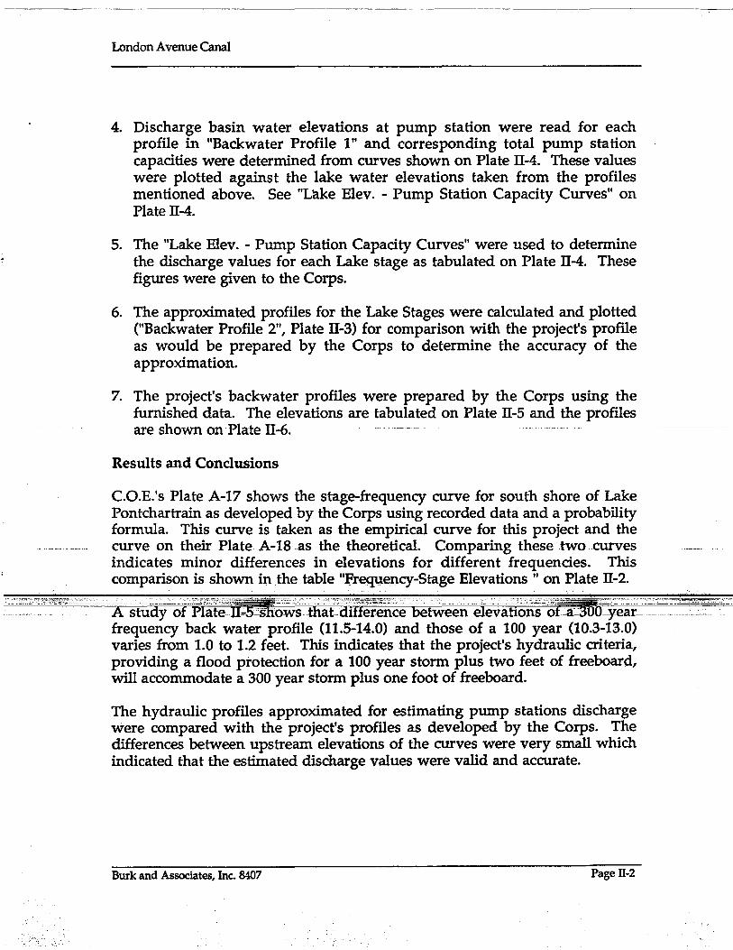
4. Discharge basin water elevations at pump station were read for each profile in "Backwater Profile 1" and corresponding total pump station capacities were determined from curves shown on Plate II-4. These values were plotted against the lake water elevations taken from the profiles mentioned above. See "Lake Elev. - Pump Station Capacity Curves" on Plate II-4.
5. The "Lake Elev. - Pump Station Capacity Curves" were used to determine the discharge values for each Lake stage as tabulated on Plate ll-4. These figures were given to the Corps.
6. The approximated profiles for the Lake Stages were calculated and plotted ("Backwater Profile 2", Plate ll-3) for comparison with the project's profile as would be prepared by the Corps to determine the accuracy of the approximation.
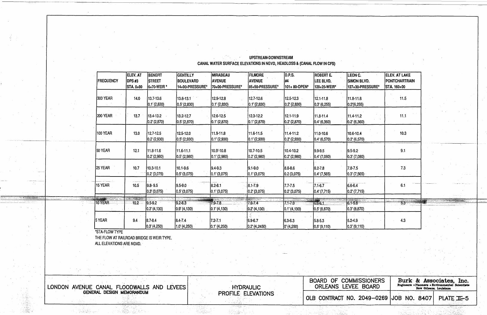
7. The project's backwater profiles were prepared by the Corps using the furnished data. The elevations are tabulated on Plate ll-5 and the profiles
-··are·shown-on-Plate ll-6. _. ----.--.--.-- .-
Results and Conclusions
C.O.E.'s Plate A-17 shows the stage-frequency curve for south shore of Lake Pontchartrain as developed by the Corps using recorded data and a probability formula. This curve is taken as the empirical curve for this project and the curve on their Plate A-IS.as the theoretical. Comparing these two-curves indicates minor differences in elevations for different frequencies. This comparison is shown in the table "Frequency-Stage Elevations" on Plate ll-2.
Astuay-orPi;t~'n~5-Jt~~~~t:ll~t:~dm~r~~~~6e~eeneieva.ti~~;-~f:;;golty~~~~; '-'-.-----~.~ .. -" - ' .. frequency back water profile (11.5-14.0) and those of a 100 year (10.3-13.0) varies from 1.0 to 1.2 feet. This indicates that the project's hydraulic criteria, providing a flood protection for a 100 year storm plus two feet of freeboard, will accommodate a 300 year storm plus one foot of freeboard.
The hydraulic profiles approximated for estimating pump stations discharge were compared with the project's profiles as developed by the Corps. The differences between upstream elevations of the curves were very small which indicated that the estimated discharge values were valid and accurate.
Burk and Associates, Inc. 8407 Page 11-2

;a rtl DO ........ Cb
;'I···rtl • Zrtl o· -< O~ C(i)
~rr1 rtl (J)
o ·lD
(")
... ~ .0 .~
·z ·0 .
C;..
o CD
Z o ·f~ ~. . .
! . . i :\ii
LEGEN.tt!:
ci ·Z
I 7 ... '" '"
I-
... 6 H--t--HI!! l!fflittf~o/'fItH
·z 05 ;:::: :: ~4
.11.1
14
13 ....
II
Iii 10 8
.....
I . ! ... I.! \::. II ·1
,· .. '···1···· I .. I .. I , I'· I':: I···· : .:. .. '"\": ... ::
.. :·::t::: I ... :,'1 ..... I···!II' .... ! ....... :! ,. ··1· .. 1····1·· I·: .. :::. ··f· .. : . I' , ,'. .. I : __
I·" :'.', ~
1'·1· .. , . . ... t-+-I--t--I--1-
1:::j;;I~ . VI··. I ..
l·· .... '1'· I··· .. 1::: 1
.': •. I' ,
10
I.' . ~.,
· .. ·1-··1-· I
T·
1-··1··· ....
Ii 1···1··+···1···
I 'I .. .1
"" 100 YUill:
.-
.4
.. i I I···
.r .1 .01 .01 .04
LEGEND
South Shore of Lake Pontchartra1n LAKE' PONTCHARTRAIN. LA •• AND VICINITY
. WIGH LEVEL PLAN DESIGN MEMORANDUM NO.13, GENERAL DESIGN
ORLEANS PARISH LAKEFRONT LEVEt -. W.EST OF IHNC
STAGE- FFiEQUENCY CURVE
u. s. ''"In [HI'HUII DISTII'CT. II[W GIlLUM' 1 ......... _. COlI" 0' [HIIHU"I I nU"M'~fll9S. . "" ••. 1i-2-29536
.. PLATE A-IS

~:;~~::-;;;~~~~,;~:: --
j
'" o ~12r-~~~~ __ ~~~~~~ __ ~~~~~~
rnrou~~-~GEE~IONSIZ11~~~~~~~~hk~~~~~~~~ FREQUENCY LAKE W.S. ELEVATION (NGVD) 8'1 0
~ r-+-~-r~~r-+-~-r-+~--r-~-r-+~~
I ~~~ ~PIRI~L ~mRrn~L ~Pffil~cm PRWEcr ; 9~~~~~~~~~~~~~~~~~~ 5 4.3 4.3 . - - 4.3 ~ 8 < r-~~-r-+~r-+-~-r-+~--r-~-r-+~~
1 0 5.25 5. 1 5 5.3 5.3 ~ 7 /--'---tF--+--+---+---+--t--+-~-+--+~--r---t----t---+--j I ~
--------·-----15 1------6.05-~- ----- ----6.05--- -- --=--=---- ------ _6.1_ - - ~ ___ 9 ___ L--
7.35 - -7.3 ~ 5 LL
25 7.3
50 9.05 9.05 9.8 9. 1 g§ 4 1-=--+-----+---I---+--I---+----4--+---+-I--+---+--r--:-+-~____I (/) .
1 0.35 1 o. 3 ~ 3 1-1 -+-f--+--I--+--I---+----4--+---+-I--+---+--r-+-f____l 100 10.25
11.151 J 11.1~_~j IIII II I II--I~+ II +--+ I 11.5 w
200 ___ 1-1-.05
300 11.45 11.5 v () I I - 1-1-- I
~~_~.:"._,~~~=--.-~;" ,-,."",,,.,:- T?iii!= .:.-;.;:-:;:-:-:~;;:~;';.~,;;:;=_~::;::;:~~ _ _=~_~~.;-:..~--= .. -.'---- ===c':==_:"" ___ ..;..~_~ ~ ______ -'.':._ .. __ ~._
·""'=-='tt(r~c.,:-, ... "-.:.cc:--O'Cc=::~=-=-§Q1~IeZ~~:~:~~~-::=~~~~~--=';:::;_3~OD~~ ---"~~:~-"~=_~~:D-c "c=~
FLOOD FREQUENCY (YEAR)
I
Burk Be Associates,' Inc. LONDON AVENUE CANAL FLOODWALLS AND LEVEES
GENERAL DESIGN MEMORANDUM
. PROJECT
STAGE~FREQUENCY CURVE
BOARD OF COMMISSIONERS ORLEANS LEVEE BOARD ~ oP1aDn81'll 0 ~ ~tIsta
NeT Orleap, LouJJdana
- .
OlB CONTRACT NO. 2049-02691 JOB NO. a407l :,R(ATE lI-2 ---~, ' . .' . '. . - .

LONDON AVE CANALBACH~ATER PROFILE! BENFT GENTL¥ HIRBU FILMR PSB4 R.E.LEE LCSIMN LAKE PSB3 SO.RR
•• ," ••••• ,.111 .... ", •••••• ,1.,111 11 ••••• '1., ••• ,11.,1 •• " •••••••• 111.' •••••• " •• ".111 ..................... ,1, •• 1 ............ ,1, •••• 111 ..... '
"1'~ ,',',""l:',··""'·,····U.'.' ••. ,I •••••• III'ii:ij': .".10' •• ,"' .......... 11111""' ... .. "' .., it l
.". " ..... 'k
~ •••• III".,I.I •• !.,III •• IIIII.IIIIII'
"--• I I I • I '" • I I I I I '" • , ,. I I • I ••••• I .... I, •• 1. ii' , I • '7' I • I •• I I •• W, I •• I , I I I • , I I , I I '" , I I •• I '" , • I ""', I • I " • I • I I • I •• u ••• I I I • I , I I I I I I I III I o ~ ~ .2-1"t. DI>o .,. " .. • • · .• .Shut 0 ff (;p..s. #3) . ..
.1 """·.;· .... · ........ ·f,,· []I";" il"~'~ _ ." .......... . 1'!Wi. II •••• ,.,.,., II II.", "'11"""" "'"'
· · e· . """ "N--~ ... _-, I", """"1:.1
· · 6· " " 11 ,,' • • I l
~O;' 1""",,',""1', ",!, "" " I! "t
••••• 1 ••••••••••••••• 1111 ••• 1 •• 1, ••• 1.11 .. '11111111·/1Iliii,b ••• I •••••• II •••••••••• ,.I ••••
~1. -~ L--------I-l~--..".---
,I" I. ""'1'", "'111'" •••• 1.1"'1" HI '1"""'1' •• ,. W"""", "'1" "11'1""1"11'1'1'1'111"11 .... __ ..
• .•. ,. , ••. I' ,.~ I ~'.""""'I '1'1' "'1 •• 1 , ••• '1.1.1, .. ,., III I I' ,. "I.I,H, I""""'" ".H •• 11 11 ••• 1.'." ......... "" I.'" II •••• ~ ....... , ....... ,., ••••• , 11'1' I .. 1'1'1'1111,,111 H ••
I ,. •• •• I' ,. , • " ,
.,' ., , • • • ., . • , . • I • • • • ,. • · i 1,1".1., •• , ..... , """",, '""I' ,.1., •• III", I"" I ................. ,; I .............. "'1"'" ••• 11.' •••••• , ••••••• ~_!...~_~"~_'.'I~ ~._~.~~_~.!.~ .!' •••• I •••••• , 1I1~'.I' ~ '."" I
• II II .• , I' '11 '.' •• I' ~
_~.:;::~~;:::~- .O=~---_-_;_-:=~~O~::;:~_;~ -~'. =- ---~,.- "-;;;-";:;;:;;~-::-==:-~;;::I- ;~:; ::::...~;;~-
(UP STREAM ElEVS. ORBITRARllY· SET)
PUMP STATION CAPACITY
PUMP STATION PS#3 PS#4
PROPOSED PS
NOMINAL CAPACITY 4.300 3,900 1,000
LONDON AVENUE CANAL FLOODWALLS AND LEVEES GENERAL DESIGN MEMORANDUM
(CFS)
APPROXIMATED BACKWATER
PROFILES
LONDON AUE' CANAL BACHWATER PROFILEZ PSfi3 SO.RR BENFT GENTLY HIRBU FILMR PSB4 R.E.LEELC~IMN LAKE
I. .• .. i.
III ••• "" ""1111"'""""'" ,.II."""", •• , •• ,.H"" III' ,r.".'M'" I •• " ••• "" •• 111
\' ~: .. : 'ii'iii/i""ii~"""'~ .. .. ~: .. 1 .................................... .. ............... ~',.,.'~'''''''j''p .-. .. . ~., •. mnn;" r:J ." .: ............... ~: ..... : ........ ~: .............. ~:::::::: : .............. ~: ........................ ," ,~ ............... ~i~~. u.g
" .\' I ~ ol.
,; '--
••• , 1111111111' ,"" •• 1.1'" .,' 1 ..... , •• , ••• , •• t "1''''; i. ii' li ... I •• I •••• I.,'"UI.(:f.QP.) •• ;I,Q~~~·I .\ . .. .
'" "1~'"''''
• i ...... If I •• II 7: , ..... 1 I ••• r •• :,:. "'50';"1 g' ~ iJ' ''\:IoI:iI ... oIiI ... oIiIiII(,·······I''''.,UI' · ·e·:,· .. ···············
I • ••
•••••• ,' •••• ,1 • ." •••••• " •••••• "1 •••••••••• 1' ••• ,1.'1 i i 1111) iii I.ill, ••••••••••••• 11I •• " ............... 1 ••• ,11.1, •• ' ... . .(.~~.) .. 7.:~ .
· ... .. " .6': .. , .... ,1 •••• , •• ::, •• ,."111, •• ,.:,:, •. 1, •••••••• 1'~':"""'I"'I'ltll .~.~~ .. ~::.2 JI0) 5.3£
"""""""111 • (5) 4.39
It .1 •• 11 •••••••• , 111"'.1 ••••••••• , •• ' ............. '., ........ ,11 ••••• 11 •• "1"'" ., •. 1"111 d. 11.1.1,.,." ........ , .•••• 1, •••••• 1.1 "'1".1'
I-~- ---'-'-· .. .. II .. n • • 4'.,1.111.11.1. I",U ••••• ".1'.' 1""' I It I' '1.'.""" I "",. 1"' •••• ," I 1 I,ll" 1.,.1 ••• " •••• ,.". 11, •• 1'." ••••• 1 •••••••• U .•••••• ,'111 •• , .. , "."" I. "'.1 "' 1
• ".1 .• ,.,., I' .. .
•• r' ••••••• I •• I I' I •• _ ••••••••• , " I •• In •••••• , •• , ••• I ......... , I"'" It,," 'I I' I I I." I" I' '",. 1 •• 1 ••••••••• IM"".I I.' "" I •• MI •• I' I' I I •• " I I '"' """" I"""" III'
• ••.. 'I •• '. I. 'I •• "' ., •
112. :' ••••• I I ••••••• ':' : •••• 1 I • , I • I I •• ':. : ' I I •• t I •• I •••• "~ : •• I ••• 1 • t • I • I • ~. : •• , I I I. 1 I • I •• I ':" :.' • I' •••••••• I '7 : . I I • I .1 I • I ~ •• '.~ : •• I I I , I •• 1 • , I , :. : ' •••• I ••• I , •• ,.:' ,
. .-I'" .1.1 •• , ••• II' •• Int.~ _., "11" II" "" _ "'"" "'", •• '"11'""1_1_" ~'.II'.' IIU ••• 11 •• ' I. 1II1 I ....... 11 ••• ,I' •• 1" '"I", .,., 1 •• 1. " •••••••••• , •• II'" II' "' "" "" ", •• I"'
I •• ... •• ,. •• ,. ,. •• • .0 II ••• ,,"1.1 •••.•• ~.!....!....!....!...!.!..~!.~ . .!....!..!.,.!.~~~I'.' 1.111," ,1'11' "'.!~~'~.!.~~.'.I' ~ 1.111 '" ••• I •• 11 I." ..... "I" ,., 1 I., I .... "_~.~~~~~~'~_I~~~_"" 1.1'1" III •• I'I'~~.~~~~.~~~~~ I • ., •• II. '" ., •• I. I I .
:...-...:-~-:~....::...-'"--.~ Pr~ReFIHE§~-~ .. :2:'--~:::;;g.~--'="~''-:·:-~~~ ;::;'2:===~""::~;_ ..
(UP STREAM ElEVS. ESTIMATED FOR LAKE STAGES)-LEGEND
(25) 7.3
o (FREQUENCY) LAKE W.S. CROSSING STRUCTURE
ELEV.
BOARD OF COMMISSIONERS ORLEANS LEVEE BOARD
Bur k & Associates,' Inc. ~ 0 PJaDDen • ED'9IroDDUllltal SclentDt.
HeY 0rleaDa, Lou1GaDa
OLB CONTRACT NO .. 20+9-0269 '1 JOB NO. 8407 pLATE:- :n:~3

-~--:-~-t-;~~~:~~-~~=-~::;:---,.;o
17 -- --- -- -- -
16 / - 3 - 1l F .. pu ~P~ f- 14 -..-. '0"-' '\ V • G:i15 .... ' -t- 13>~
(!)N W
.
'\ '01 ~ 123 1 b14 f-FE NTII - RE I\L - • II
~ 13 r\ v H( ~D -'- 1- .0' f- 11 ~~ } -
.......... UJ-I
'" :I: 12 - t- 10 .w -I ........... en· ~ 11 3 ~4 FT A ND ~. 9 .en -
2 ~2 FT P ~M :>S V '" 3:. z - 83: W10 w a::: .'" (!)Z W.
It 9 ~ 7 a::: 0 <1=
'~ 6:I: U 0 8 U::::> en en 7l I I I I I I I I I I I 5 0 "'--'
3000 3500 4000 4500
TOTAL CAPACIlY (CFS)
PUMP STATION #3
----~~- ----- -------------------
17r-r-~._~_r_,_._._. __ ~~~~~~~~~~~ 1 6 ~t>... v Dlf FEREt Tit L -+- 12
6' 15 )..-_V ~ -Ii -. HE/AD = 1 ~ .3' -+- 11'0..-.
~14 f-- .. -~~ .--.- -~- 10~ 1 ~ 13 '3 - H(IRI; DnA" F UMPS ""I'-.... .: 9 ~ D.
; _".:g._1J~l:.·:'::-:,··~ :;' .•.•......• ".--- :.c'.::.-·· '---.''-'." :~' . i":.~- ~;~.n . _ .", •• -- ..•... :. I,. " .' .. :,.d:C ~,.r.s"':-=' ., d .; ~;::. . _ '._ ,,,-.:';~:.' ,:: •. ~ t.d~~. . --.z:-
~ 11 .. - . -.. -.~:----- -.--~~. (en en
~ 10 3 - HORI ~Ot TAr- F utv PSI~17 " - 6~ ~ ~. 9 A ~D 2 - CE ~TF IFl GA" F Ufl PS"~ - 5~t5 o 8 "\ 4<: .-\. :I:U
~-- 3u ::::> 7 ,__ ._ ~ e
2500 3000 ·3500 TOTAL CAPACITY (CFS)
PUMP STATION #4
LONDON AVENUE CANAL FLOODWALLS AND LEVEES GENERAL DESIGN MEMORANDUM
4000
PUMP STATION CAPACIlY CURVES
I--~ Ie:::: .Jl: .~ I - i.o.. 1 .... - If l.;;:- I I
~ 1 Ie. Pn5 1$ I~ ~
4.5 f"...... I I~ I~ I~ I~ 1$ K , , ,1- I" ho ,g ,~ , -~
,,,. N '~ ....... ;{"l .-..-. . - r-.r.... I -1_ II~ "'! I~ ~ ......... 1 N- Il", I" . I~ I~ 1 U :'-,. I ""l 1 Ir"" I'" 1..:1 o 4.0 /' " I . I J I I I
..-" I I . I
0 It"":::, ff ~- lA 0 I ~ r-:-t- --I T'i? I I .-"'--' 1 1 .15 I
1 """- I ,
1 ~ 3.5 I I II No. 1 0 I , U ""
....., I < I I II I I'\. I~ I a..
< 1'\ 1 1 "'\. ... 1 U 12. t'\ . ,I t-:-- I -I 3.0 ,~ 'I~ I ---k. , ~
., :@ K ~
..-:.;;. .. II . '1 " , I
1'1 L"- II I ..... I.
2.5 I I.., II I l--... I I lit) h I I. . i"'4
-1 0 1 2 3 4 5 6 7 8 9 10 1112 . ---.c-lAK-E--WATER-SURFACE--ELEVATlON(NG"JD~---.. . -.
PUMP STATION CAPACllY VS. LAKE W. S. ELEVATION
SUMMARY
. LAKE W. S: - PS /13 PS #4 FUTURE PS TOTAL FREQUENCY ELEVATION-CAPACITY CAPACITY '-CAPACITY CAPACIlY·
(YEARS) (NGVD) (CFS) . (CFS) (CFS) (CFS)
=1 ".'~" - ---===.,"',., .. '-:,rv~' ~----.-:":-: 2830242;§-::::"':~ ... ~:~JOO:': '~;~·,:"-·'·62;S§.,. :.:,~~.--
200 . 11.1 2870
100 . 10.3 2930
50 9.1 2980
25 7.3 3075
15 6.1 3075
10 5.3 4130
5 . 4.3 4250
BOARD OF COMMISSIONERS ORLEANS lEVEE BOARD
--- - --------_.-.
2490 1000 6360
2640 1000 6570
3100 1000 7080
3490 1000 7565
3640 1000 7715
3740 1000 8870
3860 1000 9110
Burk & Associates. Inc. ~ • PJamaent • b'f!rvDmelltal Sol81dbt8
Nn- OrJeaD., I.ouJaaDa
OlB CONTRACT NO.' 2049-0269 I ~OB NO~84071 PLATE 1I-4 , '~'"
- --
'n ·'n'C"::::'.'nO,,"~ . ··~.:o"'· uC" .. u
ELEV.AT BENEm FREQUENCY IDPS #3 STREET
300 YEAR
200 YEAR
100 YEAR
50 YEAR
25 YEAR
15 YEAR
STA.O+OO 6+7o-WEIR *
14.0 /13.7-13.6 0.1' (2,830)
13.7 113.4-13.2 0;2'(2,870)
13.0 /12.7-12.5 0.2' (2,930)
12.1 111.8-11.6 0.2' (2,980)
10.7 pO.3-10.1 0.2' (3,075)
.----.---
10.5 ,9.8- 9.5 0.3' (3,075)
·-·='=""~··-"~-:::"""":::;:~~:;~C;':.17· ' .. ~",,:=' ~~t..:.;":::~.
~O:.ygAR·:.::~·-=·-:.:. :::::.-10:2~- 9.5-9.2 • n' • ., ,
0~3' (4,130)
5 YEAR 9.4 18.7-8.4 0.3' (4,250)
*STA-FLOW TYPE THE FLOW AT RAILROAD BRIDGE IS WEIR TYPE. ALL ELEVATIONS ARE NGVD.
UPSTREAM-DOWNSTREAM CANAL WATER SURFACE ELEVATIONS IN NGVD, HEADLOSS & (CANAL FLOW IN CFS)
GENTILLY BOULEVARD
MIRABEAU AVENUE
ALMORE .AVENUE
D.P.S.
#4 ROBERT E. LEE BLVD.
14+0o-PRESSURE* 170+0o-PRESSURE* 18S+So-PRESSURE* 1101+ So-OPEN* 1120+25-WEIR*
13.6-13.1 12.9-12.8 12.7,12.6 12.5-12.3 12.1-11.8 0.5' (2,830) 0.1' (2,830) 0.1' "(2,830) 0.2' (2,830) 0.3' (6,255)
13.2-12.7 12.6-12.5 . 12.3-12.2 12.1-11.9 11.8-11.4 0.5' (2,870) 0.1' (2,870) 0.1' (2,870) 0.2' (2,870) 0.4' (6,360)
12.5-12.0 r1.9-11.8 11.6-11.5 0.5' (2,930) 0.1' (2,930) . 0.1' (2,930)
11.4-11.2 11.0-10.6 0.2' (2,930) 0.4' (6,570) --- .. _-- - _._- .... _-- -
11.6-11.1 10.9'-10.8 10.7-10.5 10.4-10.2 9.9-9.5 0.5' (2,980) 0.1' (2,980) 0.2' (2,980) 0.2' (2,980) 0.4' (7,080)
10.1-9.6 9.4-9.3 9.1-9.0 8.8-8.6 8.2-7.8 0.5' (3,075) 0.1' (3,075) 0.1' (3,075) 0.2 (3,075) 0.4' (7,565)
~--. .. - --- -' ---~ ---- ... _-- ------
9.5-9.0 8.2-8.1 8.1-7.9 7.7-7.5 7.1-6.7 0.5' (3,075) 0.1' (3,075) 0.2' (3,075) 0.2' (3,075) 0.4' (7,715)
1._" ..
. '-'--": .. _'- --.- -,';";.- .'.-:- ... - . . .:-,..~: •• ,:---~~. ',~.o~ -"'~.' __ ,:':-_"- -.~-_~t~\:~ ~:-j:;~-~~--: ~ .
9.2-8;3 ...... ~-::=-~::..... 1'7':9J.:.8-~~~~.~_ I/J:HA
LEONC. SIMON BLVD.
ELEV. AT LAKE PONTCHARTRAIN
127+3O-PRESSURE* ISTA.160+00
11.8-11.6 11.5 0.2'(6,255)
11.4c11.2 11.1 0.2' (6,360)
10.6-10.4 10.3 0.2' (6,570)
9.5-9.2 9.1 0.3' (7,080)
7.8-7.5 7.3 0.3' (7,565)
I: ~_nn~. 6.6-6.4 0.2' (7,715)
6.1
. .
"S;S~'~'~~~U:===-"'-~'<' u
0.9' (4,130) 0.1' (4,130) ·0,2' (4,130) 0.1' (4,130) . 0.5' (8,870) 0.3' (8,870) "
"
8.4-7.4 7:2-7.1 ·6.~.7
to' (4,250) 0.1' (4,250) .0.2' (4,2450 6.3-6.3 5.8-5.3 0' (4,250) 0.5' (9,110)
5.2-4.9 0.3'(9,110)
4.3
Burk & Associates, Inc. LONDON AVENUE CANAL 'FLOODWALLS AND LEVEES
GENERAL DESIGN MEMORANDUM . HYDRAULIC
PROFILE ELEVATIONS
BOARD OF COMMISSIONERS ORLEANS LEVEE BOARD J!niin&el'll 0 PlaDDerII 0 En'YlroDmental Sclentlata
. Ne,.. Orleam. Lou1sIaDa
OLB CONTRACT NO. 2049-02691JOB NO. 84071 PlATE 31:.5 - -
.' .~ .. '

:;:
~ 0 . . > w. ~ • :..J ~ W
I-- m ~ ~ Z (/) CJ) ::> 8J I-- ~ W <! W
- :..J W ~ ~ ~ i= ffi ~ ~ ::> z z CJ) 0::: '"'"
w· 0 1--::; ~m w CDw Ow
D.P.S. #3
01 0 W W . :..J
0#91 !~~ )l~NDON AVENUE:lML CANAL III ~ ~h--D#-~.S-. ----I 8. ~:..J ...-
w THE FLOWS AT R.R., BENEFIT AND ROBERT E. . LEE • 1 ARE WEIR TYPE (FLOOD GATES AT EACH END).
ALL OTHER BRIDGES ARE FLOOD PROOFED.
15 .. • • 0 _ • • 0 .. " • .' 0 0 .. _.. .. .. o· 0 • 00 0 ..
•• • 000
(/)
I-Z. Ww ~> 0...«
0 ::; ·m
()
ZZ 00 w~ -I(/) 'W
~ o I (/)W w> ~-~~
, : ~YR. s;:~oo yR. ' , : : :~ "
~ ~:;.: : : : : : '~,3"1':" " , 50 YR. , " , , , .. , . , , , , , , , .. , .... , . . .,.. .. 10
wi ~o
z .0 n..
~ : =:', ':' 'u,"," ': ';;-:-nFi' iii .:: :: , n-; ... ~ ~10 YR" : -><=15 Y , '. I I, Q . . ~5YR:
U"--'a . ~ . .:
o >:
~.[C.:I ~ " 7'. (/)
5 ~ ,.,' , . , , ,: 0::'" t, ,:, , , , , . :.' , , , , ',' , , , , ... ' . , .. " . , . ~z w ' ~ '~ Z ' ~ . w w .
C> (/)' CD' 0 . ~,I . >
Z .,1-- ,:..J
t,-~ ,,' ,0; ~" . , ,:, ,~ .,-, -;-.-~~, , .:, , ,,-~ ,:, . , . . , ': . • -I
Z ' -. I--
, . , .', .. ' w' > w ~ ~-:::> . , « w w ~ III , --0--' ',.------Ci,-., .' . '::5." '.
,'. . ~ 'lL.
w..t :C:O~ .::> . 1-- u5 . -s. 0...
:t o o
... ,',. ,~ .. ~':""':" '.' .. ' .. ,.. . . . '.. . .. wo o· >,
:..J > CD' r:..J d 0::; CD Z.O l.L! Zoo ------c:o w -0 ~ . ,Ow' w-' 0::-1 -I(/),
15
10
5
0--'-
•• oc •• ,._ •• ~ ;-- ;;f'~~' , o. -.:'i:~' .;~< .::;; ..... "':O-~-.;;..;;'"--::-~c:.~::. :,"",:::..=-~ .. ~~-~ .. , ••. ~ ' .. :_:::c.::" -~o:;-..c~" . c.· .• ~:' ·, .. ·····:-"'"·-l=:"·-',O~~. ~:"'~~c;""'-=c __'~~;;~~~~;,,~;;~':=:;-.. -: ... -' ~:' .•. " J'i@i'Eo-,=' ~_'-' .c .• '., ..... -,"*-" "
---... .:--;;=:;..~-.-
~~'-.'~, , .
,.
C>
G:I (_)~: :....
(-)10 , .. • .. • ... .. 0 • • • • .. • .. ........
(-)15 0 10 20 30 40 50
LONDON AVENUE' CANAL. FLOODWALLS AND LEVEES GENERAL DESIGN MEMORANDiJM
60 70 80 STATION
PROJECT HYDRAULIC . PROFILES
90
BOTTOM: OF CANAL; PROFILE--
100 110 . 120 130
BOARD· OF COMMisSIONERS '. . .... ORLEANS .' LEVEE' BOARD
(-)5 .. .... - ........ - .. -
(-)10
140 . 160 (-)15
Burk & Associates, Inc. ~ oPlaDnen 0 EDnnmmental ~ent1ata
HeY Orleam, LouiIdaDa. .
OLB CONTRACT NO. 2049-0269 \ JOB' NO. 8407\ PLATElE7:p
:l:

a:: Ii· z .. ' a::
r-:' {/).
-.~ :.J CD
'W > '< 'w
~
:w·*· .:~~ '1-'- • . ' .. ~
,el"~~~~ '0'
. '..- .-'"-----'--'" --.
d 3
·m u , z z.o ·O·~ ... w_
,;;;.J (/l.
General
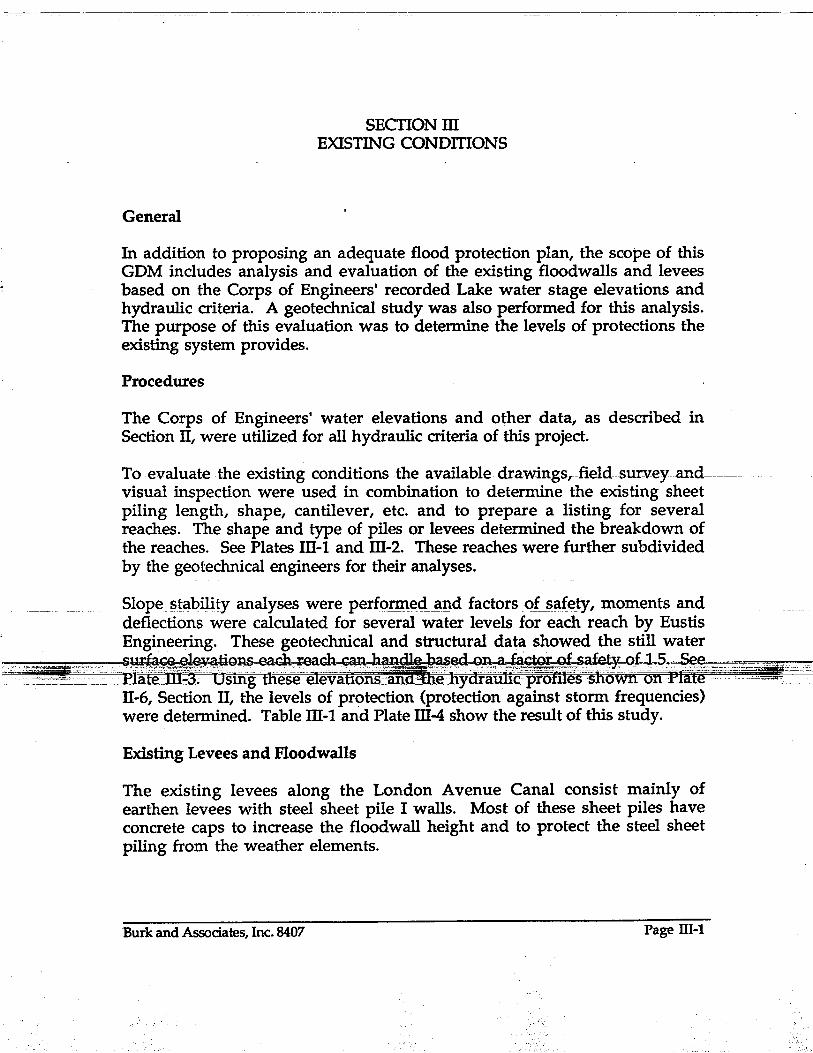
SECTIONm EXISTING CONDmONS
In addition to proposing an adequate flood protection plan, the scope of this GDM includes analysis and evaluation of the existing floodwalls and levees based on the Corps of Engineers' recorded Lake water stage elevations and hydraulic criteria. A geotechnical study was also performed for this analysis. The purpose of this evaluation was to determine the levels of protections the existing system provides.
Procedures
The Corps of Engineers' water elevations and other data, as described in Section II, were utilized for all hydraulic criteria of this project.
-To-e:v-aluate-the .existing-conditions-the available-drawings,field-surv:eyand----visual inspection were used in combination to determine the existing sheet piling length, shape, cantilever, etc. and to prepare a listing for several reaches. The shape and type of piles or levees determined the breakdown of the reaches. See Plates ill-I and m-2. These reaches were further subdivided by the geotechnical engineers for their analyses.
Slope !3tability analyses were perfo!'m~<ii3.I\d factors ol_~ClfeJy, moments and deflections were calculated for several water levels for each reach by Eustis Engineering. These geotechnical and structural data showed the still water
__ c ~~~~~~~~:-~'_ -- ~~~~:~::~:~~~~~:dt~~~lri!~~M:~~l--- -~ -~~?_~~ -11-6, Section II, the levels of protection (protection against storm frequencies) were determined. Table ill-l and Plate m-4 show the result of this study.
Existing Levees and Floodwalls
The existing levees along the London Avenue Canal consist mainly of earthen levees with steel sheet pile I walls. Most of these sheet piles have concrete caps to increase the floodwall height and to protect the steel sheet piling from the weather elements.
Burk and Associates, Inc. 8407 Page llI-l

London Avenue Canal
The present flood protection levees and floodwalls along this canal vary between elevation 8.5 NGVD and 12.5 NGVD. All of the present flood protection systems are lower in elevation than the flood protection proposed in this GDM.
The sheet piles are made of standard, special and non-standard sections in various sizes and lengths and the levees have an 8 foot crown and side slopes varying from 5:1 to 3:1. Plates m-2 and m-4 show the existing features and conditions.
Drainage Pumping Stations
The New Orleans Sewerage and Water Board's Drainage Pumping Station No.3 is located on North Broad Avenue at the beginning of the London Avenue Canal (Station 0+00). It is a masonry structure with the existing floodwalls tying into the walls of the building. The horizontal discharge tubes (from the pumps inside the building) extend directly out of the brick wall on the north side of the station and are turned downward into the canal. There also exists a series of floodgates which allow the pumping station to
-iliver-t-someofthestorm-waterto theF1orida-Avenue-€anal~-Present-level-offlood protection provided by the floodwalls at Drainage Pumping Station No. 3 is elevation 12.5 NGVD. (see Plates IV-14 and IV-IS in Section IV).
Drainage Pumping Station No. 4 is located at the intersection of Prentiss Avenue and the east levee of the London Avenue Canal (Station 101+00). The pump structure presently houses two centrifugal pumps (see Plates IV-16 and-IV-17 in Section IV). In-addition to the two centrifugal pumps three-horizontal pumps are located north of the centrifugal pump structure. Present floodwalls ac~oss this outdoor portion of the station consists of
~§~e:~~~~_":_-m- --- -----c'fo=~it~~;~I~I:~i~~;:~~~~:~s~h:~~?!-:----canal that drains the area west of the canal. The water is siphoned across the canal into the pump sump of the station and then pumped into the canal with its three horizontal pumps and two centrifugal pumps. Present level of flood protection offered by the floodwalls at Drainage Pumping Station No.4 is elevation 10.73 NGVD.
Bridges
There are nine bridges crossing the London Avenue Canal within the project limits. Two of these crossings (1-610 twin bridges) are above the required elevation and the other seven bridges are below. The overtopping elevations of these seven bridges vary between elevation 4.19 NGVD and 10.03 NGVD,
Burk and Associates, Inc. 8407 Page III-2

London Avenue Canal
which are below the design elevations, (100 year water surface profile plus two feet of freeboard).
The following schedule is a summary of existing bridge superstructure elevations (NGVD).
Crossing Location Southern Railroad Benefit Street Gentilly Boulevard Mirabeau A venue Filmore Avenue
Approximate Station
2+20 6+70
14+00 70+00 85+50
Robert E. Lee Boulevard Leon C. Simon Boulevard
120+25 127+30
Bridge Deck Elevation
9.33 8.37 4.19 7.70 6.48 5.39 6.52
Overtopping Elevation
9.33 8.37 4.19 9.27 9.15 8.64
10.03
Bottom Chord
Elevation 6.3 72 3.2 5.5 4.4 4.0 42
Typical sections of the existing bridges are shown on Plate IV-9 in Section IV.
The two elevated structures of Interstate 610 crossing the London Avenue Canal provide adequate vertical clearance above the proposed floodwall
--height The lowest elevation of-the-bottornof-thesteelgirdersis15:0-:NGVD-. -- -- ----------- ---
Results of Evaluation
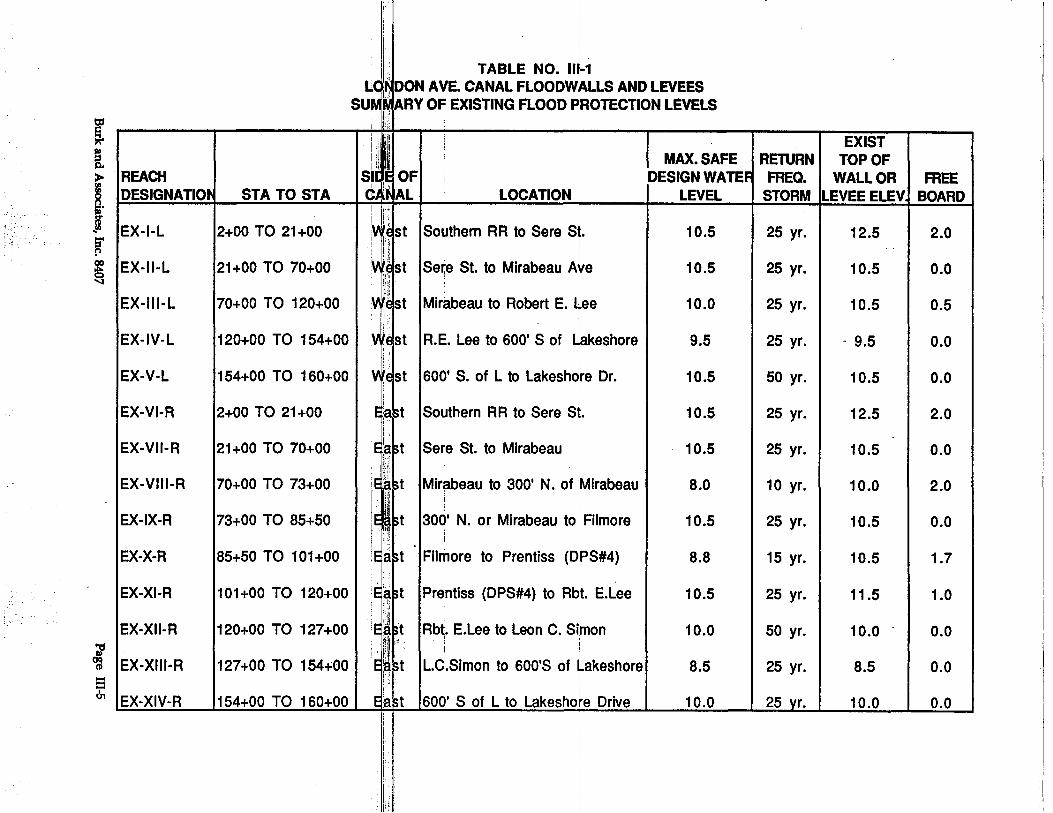
As shown on Table ill-I and Plate ill-4, the existing system and soil conditions with a factor of safety of 1.5 will accommodate still water elevations at or above a 25-year storm (with no freeboard) except for Reaches Ex-VIIT-R (good for a-10-year storm) and Ex-X-R (good for a 15-yearstorm)--which have weak pile sections. The allowable bending stress for sheet pile sections is assumed to be 18 ksi.
-'- ,:c-: co::"" 2gfr:~-'" ';,"" ---",-:;""--'C' :'-w .. : . _ __.' e'c-',,:: ~".~;. "TErE:' _ .. -: :"-':;;::""c",--.~=:'~ '>:;
-- Tlie-stOpe-stabilityanalysis for the earthen leveesaf"1ow-water" eleva.tions resulted in the following factors of safety:
Reach Factor of Safety W.E. -1.0 W.E.-3.0 W.E.-5.0
Ex-JV-L 1.5 1.4 13 Ex-V-L 1.4 13 12 Ex-XIII-R 1.8 1.65 1.55 Ex-XIV-R 1.6 1.5 1.4
The lowest recorded water elevation is - 1.0 and the lowest probable water elevation as established by the Corps is - 5.0.
Burk and Associates, Inc. 8407 Page III-3

~.-,-.- .. r .. :· .. ·~
London Avenue Canal
Real Estate
Along most of the present . levee system the existing property lines of the . adjoining property are located at the toe of the existing levee. Most of these adjoining properties are rea~ yards of residential property and frequently garages or tool sheds are constructed adjacent to the property line.
-- , - _. - -- -------- - - ----
Burk and Associates, Inc. 8407 Page III-4
r ~
'
I,
, F TABLE NO. 1I~-1 L' I, DON AVE. CANAL FLOODWALLS AND LEVEES su:~;; ARV OF EXISTING FLOOD ~ROTECTION LEVELS ~t.l ,
~
i >IREACH ~ ~. DESIGNATIO STA TO STA .... ~ IEX-I-L 12+00 TO 21+00
~ IEX-II-L 21+00 TO 70+00
EX-III-L 70+00 TO 120+00
,'I i i ~ 'i I,. , 'I··jl
S~ I!" OF, I
C,: AL
I~!i' I, !i~st i,:, !I!:' 1 I !I),
~AI~~st ~~ill'
iIi
In'
\~i,!~st ,"~i
LOCATION
Southern RR to Sere St.
I Se~e St. to Mirabeau AV
1
' e
Mirabeau to Robert E. Uee I
EX-IV-L 120+00 TO 154+00 1 YjJst IR.E. Lee to 600' S of Lakeshore
EX-V-L
EX-VI-R
EX-VII-R
EX-VIII-R
EX-IX-R
EX-X-R
EX-XI-R
EX-XII-R
~ ~ IEX-XIII-R -== 0, 'EX-XIV-R
154+00 TO 160+00 1 vtelst 1600' S. of L to Lakeshdre Dr.
2+00 TO 21 +00
21 +00 TO 70+00
70+00 TO 73+00
73+00 TO 85+50
85+50 TO 101 +00
101 +00 TO 120+00
120+00 TO 127+00
127+00 TO 154+00
154+00 TO 1 60+00 e'aM
Southern RR to Sere St.
Sere St. to Mirabeau I
I
Mirabeau to 300' N. of iMirabeau
300' N. or Mirabeau to Filmore
Filmore to Prentiss (DPS#4)
Prentiss (DPS#4) to Rbt. E.Lee i
Rbt. E.Lee to Leon C. Simon
L.C.Simon to 600'S of Lakeshore I
i
600' S of L to Lakeshore Drive
I ~ EXIST
MAX. SAFE RETURN TOP OF DESIGN WATE FREQ. WALL OR
LEVEL STORM LEVEE ELEV,
10.5
10.5
10.0
9.5
10.5
10.5
10.5
8.0
10.5
8.8
10.5
10.0
8.5
10.0
25 yr.
25 yr.
25 yr.
25 yr.
50 yr.
25 yr.
25 yr.
10 yr.
25 yr.
15 yr.
25 yr.
50 yr.
25 yr.
25 yr.
12.5
10.5
10.5
- 9.5
10.5
12.5
10.5
10.0
10.5
10.5
11.5
10.0
8.5
10.0
FREE BOARD
2.0
0.0
0.5
0.0
0.0
2.0
0.0
2.0
0.0
1.7
1.0
0.0
0.0
0.0

OVERTOPPING DESIGNATION
A B C D E F G H
BRIDGE ELEVATIONS LOCATION
SOUTHERN RAILROAD BENEFIT STREET BRIDGE GENTILLY BOULEVARD BRIDGE MIRABEAU AVENUE BRIDGE FILMORE AVENUE BRIDGE ROBERT E. LEE BOULEVARD BRIDGE LEON C. SIMON BOULEVARD BRIDGE DRAINAGE PUMPING STATION NO.3 DRAINAGE PUMPING STATION NO.4
ELEVATION
9.33 NGVD 8.37NGVD 4.19 NGVD 9.27NGVD 9.15 NGVD 8.64NGVD
.10.03 NGVD 12.50 NGVD 10.73 NGVD
T7
-~~->-~
FOR DESCRIPTION OF EXISTING SHEET PILES AND LEVEES, SEEPLATES~2AND][4
LONDON AVE. CANAL FLOODWALLS AND LEVEES BOARD OF LEVEE COMMISSIONERS ORLEANS LEVEE BOARD GENERAL DESIGN MEMORANDUM
ORLEANS LEVEE BOARD CONTRACT NO.2049-0269
-------
PLATEm-1
Burk & Associates, Inc. Engineers. Planners· Environmental Scientists
New Orleans, Louisiana'
LONDON AVENUE CANAL FLOODWALLS AND LEVEES
EXISTING CONDITIONS
.J08NO SHlET NO
t--------,----11 8407 1--"'--- 1-"'-PLAN INIWC) 01 CHECKED FilENO

______ 0 __
REACH DESIGNATION
EX-Iol
EX-II-L
STATION TO
STATION
SIDE OF
CANAL
LOCATION·
2+00 TO 21+00 I WEST ISOUTHERN RR TO SERE ST.
21+00 TO 70+00. I WEST ISERE ST. TO MIRABEAU AVE.
EX-III-L ' I 70+00 TO 120+00 I WEST IMIRABEAU TO ROST. E. LEE
TYPE OF
STRUCTURE
SHEET PILE WiCAP
SHEET PILE W,CAP
SHEET PILE W/CAP
EX-IV-L I 120+00 TO 154 +00 I WEST IROST E. LEE TO 6OO'S OF LAKESHORE IEARTHEN LEVEE
EX-Vol I 154+00 TO 160+00 I WESTl600'S. OF LAKE TO LAKESHORE DRIVE lEARTHEN LEV EE
EX-VI-R 2+00 TO 21+00 I EAST ISOUTHERN RR TO SERE ST. SHEET PILE WfCAP
EX-VII-R . I 21+00 TO 70+00 I EAST ISERE ST. TO MIRABEAU AVE. SHEET PILE W/CAP
EX-VIJI-R I 70+00 TO 73+00 I EAST IMIRABEAU TO 300' N. OF MIRABEAU ISHEET PILE W/CAP
EX-IX-R I 73+00 TO 85+50 I EAST 1300' N. OF MIRABEAU TO FILMORE SHEET PILE W/CAP
EX-X-R I 85+50 TO 101+00 I EAST I FILMORE TO PRENTISS (DPS #4) SHEET PILE W/CAP
EX-XII-R I 120+00 TO 127+00 I EAST IROST. E. LEE TO LEON C. SIMON SHEET PILE W/CAP
EX-XIJI-R I 127+00 TO 154+00 I EAST IL. C. SIMON TO 600' S. OF LAKESHORE IEARTHEN LEVEE
EX-XIV-R I 154+00 TO 160+00 I EAST 1600'S. OF LAKE TO LAKESHORE DR. I EARTHEN LEVEE * This pile section "SP.SEC1A", is a 1/4" thick Zsection, 5-3/4" deep.
Each section is 15-3/4" and the section modulus per linear foot of wall is 9.5 in.3, as per Foste( Frodingham Catalog, Special Section 1 A-RD3.
TOP OF IGROUNq CANTILEVER I TOP OF BOTTOM OFI LENGTHI SH. PILE I CROWN I CROWN I CROSS WAU E4 EL I SHEET SHEET SECTION EL WIDTH SLOPE
12.5
10.5
10.5
12.5
10.5
10.0
10.5
10.5
·9.5-10.5
4.5 8.0'
5.5 5.0'
4.5 6.0'
-------1---
4.5 8.0'
5.0 5.5'
4.0 6.0'
4.5 6.0' 1-
4.5 6.0'
5.5 5.0'
PILE EL PILE EL
9.S -10.5 2a PZ-27
7.3 -12.7 20'. I SP.SEC 1 A"
7:3 -12.7 2a M-115
9.5 1 8' 4:1
10.5-11.51 8' 3:1
---1-------------1------- 1---- -----.- --·-1-- 1---- -·-1-- -------.-.
9.5 -10.5 2a PZ-27
7.3 -12.7 2a ISP. SEC 1A'
6.8 -132 2a MP-112
7.3 -12.7 20' MP-115
7.3 -12.7 2a I "ZIGZAG""
7.5 -12.5 2a PZ-27
8.5-10.0 8' 5:1
10.0-11.01 8'(+1-) 5:1 * * This pile section "ZIG ZAG", is . in a shape of corrugated steel sheet,
1/4" (+/-), thick. The corrugations are folded (not wrinkled) 90 degree angles with 4" legs. Each section has 5 corrugations.
All elevations are NGVD.
Burk &; Associates, Inc . LONDON AVENUE CANAL FLOODWALLS AND LEVEES
GENERAL DESIGN MEMORANDUM TABULATED
EXISTING CONDITIONS
. BOARD OF COMMISSIONERS ORLEANs LEVEE BOARD EuPeezw 0 PlaDDezw· 0 ED'rironmeDtal SoJenttsta
HeY OrleaDa, I.ouidaDa
OLB CONTRACT NO~· 2049~0269 :1 Joe· NO. 84071 PLATE :m:-2 ~ - -

REACH DESIG- ' NATION
EX-I-L
EX-II-L
STATION SIDE LOCATION TO OF
STATION CANAL
2+00 TO 21+00 I WEST ISOUTHERN RR TO SERE ST.
21+00 TO 70+00 I WEST ISERE ST. TO MIRABEAU AVE.
EX-III-L I 70+00 TO 120+00 I WEST I MIRABEAU TO ROBT. E. LEE
EX-IV-L I 120+00 TO 154 +00 I WEST I ROBT E. LEE TO 600'S OF LAKESHORE
EX-V-L I 154+00 TO 160+00 I WEST 1600'S OF LAKE TO LAKESHORE DRIVE
~~------- ----- -. -- ~~IEXNI-R 2+00-1021+00 --I 'EAST-ISOUTHERN RR-T0-SERE-Si-;------
-
EX-VII-R I 21+00 TO 70+00 I EAST ISERE ST. TO MIRABEAU AVE.
EX-VIII-R 70+00 TO 73+00 EAST IMIRABEAU TO 300' N. OF MIRABEAU
EX-IX-R 73+00 TO 85+50 EAST 1300' N. OF MIRABEAU TO FILMORE
EX-X-R I 85+50 TO 101+00 I EAST IFILMORE TO PRENTISS (DPS #4)
:.=.=i-..i-~i:i3-i-.,. ;-~~_ ~"-"-=--_:::..:: __ ~_ ~.~_~~.,.-...,~ o'IJ:'Y~YI~R :.-1 .1 n1 ,J.nn:rr'L1?/"1J:nrlhl~si:;:;lptmNTl~~ tnP~':lMV"T(1'I;Ul)I:rr'~P~ll=l=c -';-.~:.~~ ',,1,,·,·=,- '
EX-XII-R I 120+00 TO 127+00 I EAST IROBT. E. LEE TO LEON C.SIMON
EX-XIII-R I 127+00 TO 154+00 I EAST IL C. SIMON TO 600'S. OF LAKESHORE
EX-XIV-R 1 154+00 TO 160+00 1 EAST 1600' S. OF LAKE TO LAKESHORE DR. * Assumed 1/4" Thickness
LONDON AVENUE CANAL FLOODWALLS AND LEVEES GENERAL DESIGN MEMORANDUM' , "
: ~I .
. ,',-,: .
SHEET PILE SECTION
PZ-27
TYPE, OF
STRUCTURE
SHEET PILE W/CAP
SP. SEC 1A ISHEET PILE W/CAP
M-115 SHEET PILE W/CAP
EARTHEN LEVEE
EARTHEN LEV EE
SOIL F.S.> 1.5 I PILE fb:: 18KSI· ' TOP OF I SEC. MOM'OF MAX MOM fb 'DEFL' DEFL MAX WALL EL MODULUS INERTIA SAFE FT.- K KSI IN. "IN. SAFE
1N3 1N4 WSL WSL
12.5 30.2 181.2 I 10.5 I 7:0 I 2.8 I 0.2
10.5 9.5 27.3 10.5 I 8.1 I 10.2 I 1.35
10.5 5.4 8.8 10.3 I 9.9 I 22.0 I 5.2 I 3.8 I 10.0
, -. -PZ-27- . -ISHSSTR-ILE- W/CAP--I·--t2.5--1---30.2 181.2.1 10$1-8.0 L3.2 I 0.2 _I __ ..:-----I~-~_I.
SP. SEC. 1A ISHEET PILE W/CAP 10.5 9.5 27.3 10.5 I 10.5 I 13.3 I 1.9
MP-112 SHEET PILE W/CAP 10.0 2.4 1.6 10.0 9.8 49.0 30.0 5.6 8.0
MP-115 SHEET PILE W/CAP 10.5 5.4 8.8 10.5 8.0 17.8 4.2
------.-'ZIG ZAG" ISHEET PILE W/CAP , 10.5 2.0* 2.8* 10.5 I 8.6 I 51.6 I 15.0 I 2.9 I 8.8
·1
----.--
~---= _c, -'-~~~'_ ~~F~~~-~.:"--Z2Oz==I~~ '\1:&~~:I.·~U;!!!:l~~~~=~I~~=="·='~ "'=:'=O'~'="=~:~I?'tIt=
PZ-27 SHEET PILE W/CAP
EARTHEN LEVEE
EARTHEN LEVEE
EXISTING SHEET. PilE DATA
9.5-10.5
----
30.2 181.2 I 10.0 I 3.5 I 1.4 I 0.06
BOARD OF COMMISSIONERS ORLEANS LEVEE BOARD
Burk & Associates, me. EilItDeeJ'B 0 PlaDnen • ED'rironmental Sclauttst.
Hew Orleans, Louisiana
OlB CONTRACT NO. 2049-02691JOB NO. 84071 PLATE m-3

.:~
D.P.S. #3
REACH EX-I-L REACH EX-II-L REACH EX~III-:L
Z ~ ~ ffi r ~ w <! W
- -I W 0::: ILL. a:: rn 0 r W ro W « . . ~a:: Z . Z> -f./) o:::W 3W
We)
r~ O:::rn W rnw Ow 0:::-1
REACH EX-IV-L o ~
·m u Z Zo
0:::E w-I-if) 010. Wr .W:..J 'L ""'"> ;:-2;: 0
I (1)'" m T ~ I u" g I ~;( ~ - ~ h ~~ LONDON AVENUE OUTFAll. CANAL 1\ II la~ D.P.S. I, REACH
IU:> REACH ~ #4 rr- REACH EX-XIV-R 1 EX-VIII-R ~ W EX-XII-R - ~>
REACH EX-VI-R REACH EX-Vll-R REACH REACH 0... « REACH RF.ACH EX-XIII-R EX-IX-R EX-X-R EX-XI-R
REACH EX-V-L
Wi ~o
W 1 z 0::: 0 o c... I [/)w w> ~-::sgs
PLAN
J 0 .. : ..... '. . . ... ~~: .1 ~.~. .; ..... '.' . To0.p. ~F S~~E!. ~:I~E~. . . ... : .. To°~. ~~ ~~~K.H~D . ...;, ~ .T9P .:.9.F. LEYEs..;...;,.J'"' d .i6·. )\~; . . EL. 7.3 . .. EL. 9.5·. -' . EX-V-L
"-:;'O+++W-- _ ...... -- .. ~ ·1....111111 --:---llrrr:----·- . : g : EX-IV-:L : g g EARTHEN
o 0 ------ . + . -. . . _ -:-EL.-4.5-:--- + EARTHEN LEVEE . + + LEVEE >: . 0 ~ EX"':'I-L N . EX-II--:L' . EX-III-L' ~ SWL =. 9.5 (8.5 ·EAST SIDE:) ~ g SWL 10.5 <.?,' ...• ~: •• 'PZ~'27"" ~ ..... : .... 'FqSTER'1A ~..... ........ . .. ':'MP~1'15~"'" .... ...- ..... : .. 25 YR;······:·..-··· - '-·(io.6 'EAST' Z ~ SWL = 1 0.5 ~ SWL = 10.5. <i. SWL.= 10.3 (10.0)* -< rF.s. :;:: 1'25@'LOWSWLl-<tJ;'SIDE)
___ ._2 [/) _---.3.5:YR. : if) .. ·25 YR.. . t:; . . 25 YR. . tn L EX-:-IV-L & ~X-V-L J tn tn 50 YR. o - ~.-.- -~ ... -. -. ..-~- ---.... .. -.. ~~----- .- ._._------ .------- . -. -.-~ -. ~ --.-.~~- -- -- --- --- --.---~
~_.( -: ).1 ~ . . . . . . . . . . . . . . . . . . . . . . . . '. . 1 -I' . . . . . . . .: . . .. . :. . . . . . :. .. . - . . . . . . . . w . . ..... .... -I . W . El. -12.7
WEST SIDE PROFILE .C -)?-9 . : ...... : ... : .. : ...... ~ ; ..... : ...... : ...... : ...... :. STATION ~ .. \-:--:- .~9D"9~ . C?F: ?f:l~ET.P.I) .... E~ .... : ...... ~ ~~qS;5I!'1<;;~ . ~~E .. NPT . $~q~N . qN. P~QR.L~
. ~ 19 2:0· J:O 4:0 50 60 . 7,0 - - 80 9:0 1 QO 110 1 20 1 ~O. 140 - 1 $0 . 1 qO _ =J __ . Et:. 12.5· : :.: EL. 6.8 : EL. fo.o : : EL. :".5: :: : ....;:/ EL. 10.0
JO .. : til" . a:.·9.!5·i .. J ............ ~~:",:~~.~._.: .. 'n" -: •• " .~ •••• : •• E\~.~~:.:. .... :IIIIl1 .... :: ... lmll;'L.~~·P_~~EL.:..§.2. TO_1?·L ~ .. )"9. 1.1:0. ~~~=-d...-::':.~-:-_=-~.~O~~~~ -'.0" __ "
.:c:.::,.-"::::"-,:=o-~" .. =="d~··-~=:,_:c~=-~c:·:,:c,,.c"'::''C - ----- - --- . --_._-- u~~'E'Ei7cC'"
. -:-~EAR-"FH ~N: LEVEE·~ •.. EARTH EN _ .. ==::1'"",,=,-,--. o . o· . 0 - o· SWL=B-.5 g LEVEE -o-EL. .4.0 I[) EX-X-R gEX-XI-R 0 0 . 25 YR. + SWL=10.0
... =:~ .... ~. "u::::~ EC ~L::'" g ~~-:=~~!-V~I-~:""'-.--: ..... ~ "l + EX-VI -R .+. . . .. FOSTER· 1/0; • . EX '-V I ll-R 0 > 0 C'oI ..... ..... 00' f'...
EL. ~.O-
···~~~~~t ~~~~~~~!~ ;. ~~c~'fl~' .~ r"B':~x'-'x;,~~:"" .~ 'f" fiFL~.·~istCi -< SWL~1 0.5 -< ($WL=8.8 . 25· YR. . .: PZ-27 : <i..L 25 YR .. --.J I--' ~-,,~ tn 15 YR.)* ~ ~ ~ .SWL=10.0: - tn
. : ... \ ... ' .. IJII.I .. : Vl. .' .... " ... __ .5.0._YR. . . . . . . . . ..•........
cj . ....•.... PZ:-27 N SWL = 1 . . MP-112.
:i . ~ SWL '" 1 0.5 25 YR. . SWL. = 10.0 « if) 25·YR. 25 YR.-:-tn z .
~ (-)10 : .. : ...... '. - ... :(SWL::8:0~~OYR.) ~ . . . ~~~~~~i
~. .. . . EL. ~12.'7 :L.- EL -13 .. 2 w EL.- -12.7
* BASE[} ON ........... . . STRENGTH OF .. : . . .. . ..... ; ..... -: ...... :' STATION :
.C -: );20 . ; ·SHEET· PJLES· . . . :. : . . 50 sO 70 80 6 1D 2.0 30 40 90
LONDON -AVENUE CANAL FLOODWALLS AND LEVEES EXISTING STRUCTURES AND LEVELS ·OF PROTECTION -
GENERAL DESIGN MEMORANDUM - -
EL. -12.5
EAST SIDE PROFILE . 11,,1" ..... " . . tll'll '. CROSStNGS . ARE' 'NOT' SHOWN' ON' PROFILE
100 110 120 130
BOARD OF COMMISSIONERS ORLEANS LEVEE BOARD
. . 140 150 160
Burk & Associates,Inc. Enatneen 0 PlaDnenI 0 ED'riromnaDtal So1enttBta
N_ Orleam, lmdB1aDa
OlB CONTRACT NO. 2049-0269 I JOB NO. 84071 PLATElII-4

General
SECTION IV PROPOSED IMPROVEMENTS
The existing floodwalls, levees and crossings, as discussed in Section II, provide a flood protection for 25 years storm and less without freeboard. The proposed system, when completed, will protect against a flood with elevations 12.3 NGVD at the Lake and 15.0 NGVD at the upstream end, DPS No.3. This is 4.3 to 5.0 feet above a 25 year storm and is established as a 100 year storm plus 2 feet of freeboard. Due to limited available funds, these improvements are proposed to be made in three phases.
Phase I.
Upgrading the crossings at Southern Railrc;>ad, Benefit Street, Gentilly Boulevard, Mirabeau Avenue, Filmore Avenue, Robert
______ E.Lee BouleV'ard_and~R-C.Simon_Bouleyarrl.___ __ ~ ___ ~ _____ _
Raising the earthen levees from Robert E .. Lee Boulevard on the west and Leon C. Simon Boulevard on the east to Lake Pontchartrain.
Construction of new I-walls from Filmore Avenue to the earthen levees from Mirabeau Avenue to 300 feet north of Mi!~b~!lJ! Avenue,eC}st side, and from Sere Sn-~tt~JpOO feet north of Sere Street.
Raising _ the floodwalls of DPS No.4.
PhaSen:---- --
Construction of I-walls from 1600 feet north of Sere Street to Filmore Avenue and from DPS No.3 to Sere Street.
Raising the floodwalls of DPS No.3.
Phase ill.
Installation of concrete cap over the new sheet piles and removal of the old sheet piles.
Burk and Associates, Inc. 8407 Page JV-l

--------.. ~__,__-----____c_---
London Avenue Canal
The total cost of Phase I is estimated at 11.6 million dollars which is within the available budget and Phase II is estimated to cost 12.6 million dollars. Since the construction of Phase III will not upgrade the overall flood protection, it is recommended to be performed when additional fund becomes available.
The proposed improvements are shown and summarized in Plates IV-I, IV-2, IV-3 and IV-4.
Earthen Levees
The levees adjacent to the London Avenue Canal require upgrading to conform to the design water elevations obtained from the U.S. Army Corps of Engineers, which is required by Orleans Levee Board for this project. This design calls for a 100 year flood still water -surface elevation in the canal at Lake Pontchartrain of 10.3 NGVD. The design criteria also requires a two foot freeboard in the canal, raising the required levee elevation to 12.3 NGVD at the Lake. Along the perimeter of the Lake, the Corps of Engineers is raising the levees to elevation 17.5 NGVD east of the London Ave. Canal and lS.0
-NGVD west ofthe-eanal.--Theseele-vations-include. waveaction-and-three...feet of freeboard. The project design criteria allows two feet of freeboard for levee design within the confines of the canal. There will be an area of transition of the levee from elevation 12.5+ to 17.5, west levee and lS.0, east levee near the Lake to tie into the lakefront levee system. These transitions are about 750' long each.
Ihel<?fi).tion of th~sgJ~yees, as established by the_geotechnical invesggCition performed by Eustis Engineers, requires the centerline of the upgraded levee to be setback from th~ existing.
:--::~-':l_~si!ba:cks--~~r-itrin1:'a'few feefto' appr(,Xii~1~I1ifteetlaffifs1i1eO¥' the existing levee and require no additional right of way. The typical levee sections are shown on Plates IV-5, IV-6 and IV-7.
Steel Sheet Pile I-Walls
Due to right of way restriction, none of the existing sheet piles can be replaced with only earthen levees. The proposed system calls for higher and stronger sheet pile I-walls than the existing with the same concept, steel sheet piles in low levees. Some of these levees are proposed to be improved (graded or raised) within the existing right of way. The pile sections were selected for different locations based on soil and loading conditions. Plates IV-I, IV-2, IV-3 and IV-4 show the breakdown and summary of the proposed floodwalls. See Plate IV -S for typical sections of sheet piles in levees.
Burk and Associates, Inc. 8407 Page IV-2
~:." ....

----- ------,.--------,-----,--------
London Avenue Canal
Floodproofing of Crossings
Except 1-610 twin bridges, all crossings within the project site have an overtopping elevation lower than the design flood and will be floodproofed as part of this project. The Leon C. Simon Bridge has the highest top elevation, 10.03 NGVD, and will be improved last. However, all bridges are proposed to be floodproofed in Phase I. Table IV-I summarizes openings and improvement of the bridges and Plate IV -9 shows the existing typical sections. Alternate studies were made to determine the most economical and feasible concept for each crossing's improvement. For typical details and sections of these alternates (flood gate, bridge modification and new bridge) see Plates IV-I0 through IV-13. Each bridge is discussed individually, as follows:
Southern Railroad Bridge
The Southern Railroad Company owns two sets of tracks which cross the London Avenue Canal between Drainage Pumping Station No.3 and Benefit Street at approximately station 2+00. The structure is approximately 160 feet long and 28 feet wide. The bridge consists of a sub-structure composed of
_~ ~ ~~_ ~~ ___ ~_eight~~ concrete caps_each supported_hy_elgh_Ls_teel~pipe __ piles_and_Qn~_large:r: concrete cap with ten steel pipe piles. The superstructure consists of a solid concrete deck supporting the creosoted cross ties and two sets of rails. The concrete deck has weep holes and open joints at every bent. For a typical section of the existing bridge, see Plate IV-9.
The structure,including the rails, has a top elevation of approximately 9.33 NGVD and a bottom ~ chord elevation of 6.3 ~ NGVD. The top elevation is below the required fiooclwarr elevationof15.0 NGVD at this location. The bridge cannot be easily modified without a major cost increase to provide a
~~ •. c-;~c~t~~~~~"-c~~;ccWbilIQitOfallmVitm~Jr~g~--~-c"~~~~~~- :~CY.7:~C:C~ _ .. ~~ _______ I"e_-.=,~_-'-~~ -'-~ ~-.. = .. - _-,-.. ,.ccc=,'?,==::=-:o."",=,
two alternates for providing necessary flood protection were considered- a new bridge and floodgates.
Constructing a new bridge to provide vertical clearance above the design high water level of 13.0 NGVD would be very costly (estimated over 5 million dollars) and would put the tracks out of service for a long time. Therefore, this GDM proposes constructing steel swing gates at both bridge approaches where the railroad crosses the floodwalls. PZ-22 steel sheetpiles driven 15 feet below the base of the structure will be provided for seepage protection at each gate monolith. The opening size of the floodgates will be 28'-10" wide by 5'-9" high and will cost approximately $265,000 for both gates. For details see Plate IV-IO.
Burk and Associates, Inc. 8407 Page IVo.3
-----c,..,.-----~____:_~~~~~~--~~------ -~----------- -----------
London Avenue Canal
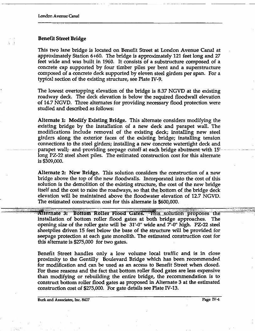
Benefit Street Bridge
This two lane bridge is located on Benefit Street at London Avenue Canal at approximately Station 6+60. The bridge is approximately 121 feet long and 27 feet wide and was built in 1960. It consists of a substructure composed of a concrete cap supported by four timber piles per bent and a superstructure composed of a concrete deck supported by eleven steel girders per span. For a typical section of the existing structure, see Plate IV-9.
The lowest overtopping elevation of the bridge is 8.37 NGVD at the existing roadway deck. The deck elevation is below the required floodwall elevation of 14.7 NGVD. Three alternates for providing necessary flood protection were studied and described as follows:
Alternate 1: Modify Existing Bridge. This alternate considers modifying the existing bridge by the installation of a new deck and parapet wall. The modifications include removal of the existing deck; installing new steel girders along the exterior faces of the existing bridge; installing tension connections to the steel girders; installing a new concrete watertight deck and parapetwalli--and-pr-ovidingseepagecutoff--at-each bridge-abutment-with 15'--- ---long PZ-22 steel sheet piles. The estimated construction cost for this alternate is $309,000.
Alternate 2: New Bridge. This solution considers the construction of a new bridge above the top of the new floodwalls. Incorporated into the cost of this solution is the demolition of the existing structure, the cost of the new bridge itselfand the cost to raise the roadways, so that the bottom of the bridge deck elevation will be maintained above the floodwater elevation of 12.7 NGVD. The estimated construction cost for this alternate is $600,000.
-.. _._~~, ._. -,-, __ -,,,o~_"~_ 0, .. ---" _--_-- ._'c,._-.--.... _ .• _;_ .. '-_"._-•• -~-'--.- : .• -, - _ - ___ -. .• _-" . ' -. - - .- ' .. '- •. '--. -, •. ,--._ .. _- m_--"_"",": .. , .... -:-', ... " ... , .. _;._-<i~ ... ~ .. ,'" "'.,- - _.
--~~ _-_·.···Aiteiiiafe '3::-:Uoftom' Roller' FlooaH-Gales._:-~lris~_soluHori:·.proposes" tlie'--installation of bottom roller flood gates at both bridge approaches. The opening size of the roller gate will be 31'-0" wide and 7'-0" high. PZ-22 steel sheetpiles driven 15 feet below the base of the structure will be provided for seepage protection at each gate monolith. The estimated construction cost for this alternate is $275,000 for two gates.
Benefit Street handles only a low volume local traffic and is in close proximity to the Gentilly Boulevard Bridge which has been recommended for modification and can be used as an access to Benefit Street when closed. For these reasons and the fact that bottom roller flood gates are less expensive than modifying or rebuilding the entire bridge, the recommendation is to construct bottom roller flood gates as proposed in Alternate 3 at the estimated construction cost of $275,000. For gate details see Plate IV-13.
Burk and Associates, Inc. 8407 Page IV-4
London Avenue Canal
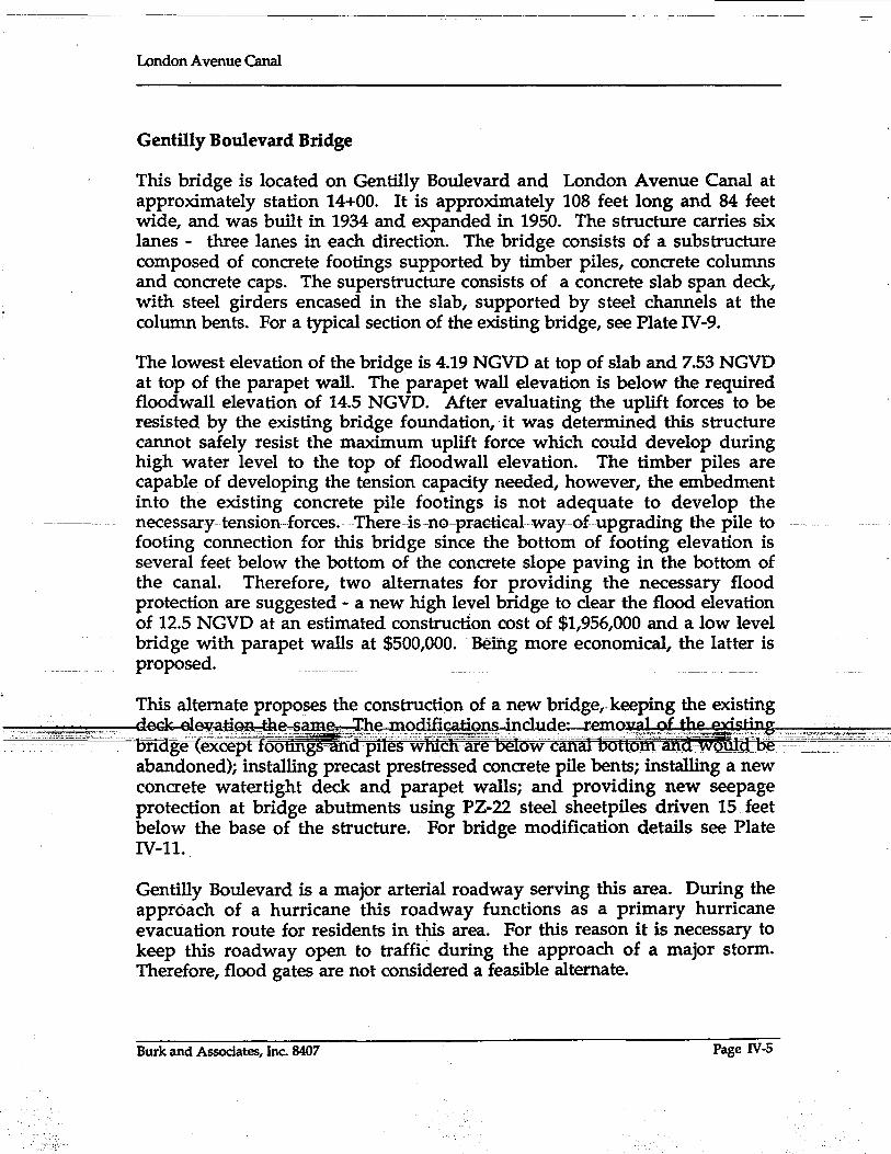
Gentilly Boulevard Bridge
This bridge is located on Genti1ly Boulevard and London Avenue Canal at approximately station 14+00. It is approximately 108 feet long and 84 feet wide, and was built in 1934 and expanded in 1950. The structure carries six lanes - three lanes in each direction. The bridge consists of a substructure composed of concrete footings supported by timber piles, concrete columns and concrete caps. The superstructure consists of a concrete slab span deck, with steel girders encased in the slab, supported by steel channels at the column bents. For a typical section of the existing bridge, see Plate IV-9.
The lowest elevation of the bridge is 4.19 NGVD at top of slab and 7.53 NGVD at top of the parapet wall. The parapet wall elevation is below the required flood wall elevation of 14.5 NGVD. After evaluating the uplift forces to be resisted by the existing bridge foundation,· it was determined this structure cannot safely resist the maximum uplift force which could develop during high water level to the top of floodwall elevation. The timber piles are capable of developing the tension capacity needed, however, the embedment into the existing concrete pile footings is not adequate to develop the
-~-~-----~- -- necessar-y-tension-forces. -- There-is -no-pr-aGtiGal-way-ofupgr-ading-the-pile- to footing connection for this bridge since the bottom of footing elevation is several feet below the bottom of the concrete slope paving in the bottom of the canal. Therefore, two alternates for providing the necessary flood protection are suggested - a new high level bridge to clear the flood elevation of 12.5 NGVD at an estimated construction cost of $1,956,000 and a low level bridge with parapet walls at $500,000. Being more economical, the latter is proposed.
This alternate proposes the construction of a new bridge,-keeping the existing
-~~rr=~- ~~-~~~~ __
abandoned); installing precast prestressed concrete pile bents; installing a new concrete watertight deck and parapet walls; and providing new seepage protection at bridge abutments using PZ-22 steel sheetpiles driven 15 feet below the base of the structure .. For bridge modification details see Plate IV-ll.
Gentilly Boulevard is a major arterial roadway serving this area. During the approach of a hurricane this roadway functions as a primary hurricane evacuation route for residents in this area. For this reason it is necessary to keep this roadway open to traffic during the approach of a major storm. Therefore, flood gates are not considered a feasible alternate.
Burk and Associates, Inc. 8407 Page IV-5

London Avenue Omal
Mirabeau Avenue Bridge
This bridge is located on Mirabeau Avenue at London Avenue Canal at station 70+00. The bridge is approximately 125 feet long and approximately 70.4 feet wide, and was built in 1960. The structure carries four travel lanes -two lanes in each direction. The bridge consists of a substructure composed of a concrete cap supported by twelve steel piles per bent and a superstructure composed of a concrete deck supported by twelve steel girders (see Plate IV-9. Adjacent to the bridge is a timber pedestrian bridge.
The lowest elevation of the bridge is 7.70 NGVD at the top of the slab and 9.27 NGVD at the top of the parapet wall. The parapet wall elevation is below the required floodwall elevation of 13.9 NGVD. Three alternates for providing necessary flood protection are suggested and described as follows:
Alternate 1: Modify Existing Bridge. This alternate considered the installation of a new deck and parapet walls. The modifications include: removal of the existing deck; installing new steel girders along the exterior faces_ of the existingJ:>ridg~;inst~J~g_!~~i~J1 c()nnect()!,s_"to the existing_~~,~l _______ _ girders, piles and caps; installing a new concrete watertight deck, parapet walls and pedestrian sidewalks; and provide new seepage protection at bridge abutments using PZ-22 steel sheetpiles driven 15 feet below the base. of the structure. Additionally, the adjacent pedestrian bridge will be removed. The estimated construction cost for this alternate is $457,000.
Alternate 2: New Bridge. This solution proposes the construction of a new ---'--"high level bridge. Incorporated into the-coscof this solutiortWill be the
demolition of the existing structure, the cost of the new bridge itself and the
'., .. c~""· .. ".';-'#¥~::D~~i~~d:::v~~th~Wfl!ad:a~~:.t~~::~~~ri£~v~,~u~e~~~~n will .. ~". --.-- - - -----~'o"_~". . . __ ,." •• _.--" _ _ __ _ . ________ .--<_~l~~.- .. - - - _. ----- --.- ---- . "
------------- -----------
The pre1imfuary design of the proposed new bridge would increase the bridge length to 700 feet. The proposed bridge is a concrete slab span structure. The estimated construction cost for this alternate is $1,849,000.
Alternate 3: Bottom Roller Flood Gates. This alternate suggests the installation of bottom roller flood gates at both bridge approaches. The opening size of the roller gate will be 75 feet wide and 7 feet 3 inches high. The estimated construction cost for this alternate is $408,000.
It is not a practical solution to close the bridge during the flood period as suggested in Alternate 3. In addition, the cost differential between Alternate 3 and Alternate 1 is relatively small. The cost of Alternate 2 is substantially more than Alternate 1. Therefore, Alternate 1, bridge modification at a cost of
Burk and Associates, Inc. 8407 Page 1V-6

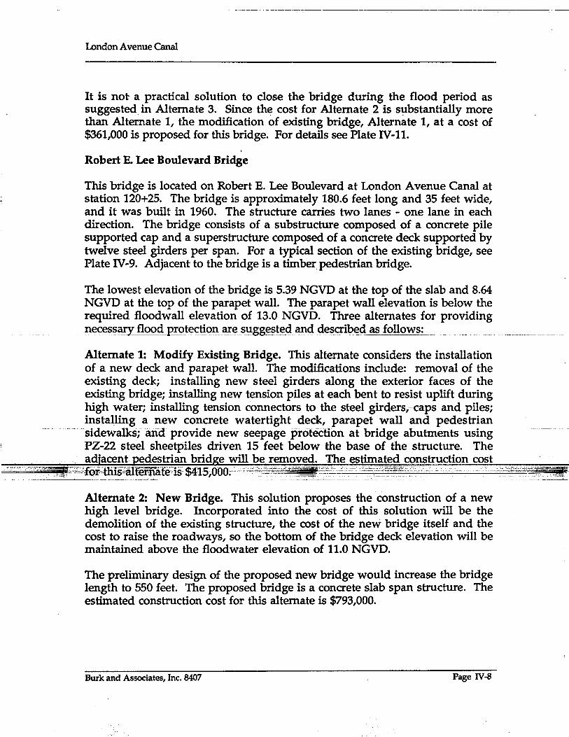

London Avenue Canal
Alternate 3: Bottom Roller Flood Gates. This solution proposes, the installation of bottom r~ller flood gates at both, bridge approaches. 1Jte opening size of each roller gate will be 40'-0" wide and 9'-6" high. The estimated construction cost for this alternate is $325,000 .
. Robert E. Lee Boulevard is an arterial roadway serving this area but is in close proximity to the Leon C. Simon Blvd. bridge which has been recommended for modification and can be used instead of this crossing during a flood. For these reasons and the fact that bottom roller flood gates are less expensive than floodproofing or rebuilding the entire bridge, the recommendation is to construct the bottom roller flood gates (estimated cost $325,000) as proposed in Alternate 3. For gate details see Plate IV-13.
Leon C. Simon Boulevard Bridge
This bridge is located on Leon C. Simon Boulevard' at London A venue Canal at approximately station 127+50. The bridge is approximately 184 feet long and 71 feet wide, and it was built in 1967. The structure carries four travel
_________JCl.ne~ __ ... _~QJ~~~s_ in_ eachc:ii.!ection. Th~1:>:r!clg~_fOll.~ist~QL~ !)ubstr!lc:t~~ __________ _ composed of concrete caps each supported by nineteen steel piles per bent and a superstructure composed of a concrete deck supported by twelve steel girders per span. For a typical section of the existing bridge, see Plate IV-9.
The lowest elevation of the bridge is 6.52 NGVD at the top of the slab and 10.03 _ NGVD at the top of the parapet wall. The parapet wall elevation is below the required flood wall elevation of 12.6 NGVD. Three alternates for providing necessary-flood protection are suggested and described. -as1611ows:
Alternate 1: Modify,Existing Bridge. _ This alternate considers the installation -• of teIi.Si0hS-OO~~h@gi§:tlj;\g-;':·st-e-e-1~-i-fdersF&ps··~~ft~~~d::":;""~·=:':."
construction ofnew-paiapefwallsparaIlel to the centerline of the-oriage-aIong -each edge of the bridge deck. Additionally new seepage protection at bridge abutments using PZ-22 steel sheetpiles driven 15 feet below the base of the structure will be provided. This existing bridge has a watertight deck and therefore, for interim protection, replacement of the existing deck is not necessary. The estimated construction cost for this alternate is $176,000.
Alternate 2: New Bridge. This solution proposes the construction of a new high level bridge. Incorporated into the cost of this solution is the demolition of the existing structure, the cost of the new bridge itself and the cost to raise the roadways, so that the bottom of the bridge deck elevation will be maintained above the floodwater elevation of 10.6 NGVD.
Burk and Associates, Inc. 8407 Page IV-9

London Avenue Canal
The preliminary design of the proposed new bridge would increase the bridge length to 700 feet. The proposed bridge is a concrete slab span structure. The estimated coristruction cost of this alternate is $1,907,000.
Alternate 3: Bottom Rolle! Flood Gates. This solution suggests the installation of bottom roller flood gates at both bridge approaches. The opening size of each roller gate will be 75 feet wide and 8 feet 6 inches high. The estimated construction cost for this alternate is $424,000.
For this crossing, the obvious choice is the modification of existing bridge with estimated cost of $176,000 which is the most economical and the roadway will be open to traffic during a flood. This bridge will also be used for Robert E. Lee Boulevard traffic. See Plate IV-II for bridge modification details.
Drainage Pumping Stations
1. New Orleans Sewerage and Water Board Drainage Pumping Station No.3 (Station 0+00). This pumping station is located just north of the infersectlOn or-N.-Broad- Avenueand Lonnon-Avenue ana- marK-g--Ule beginning of the London Avenue Canal. Since the station is situated across the south end of the canal, the current level of flood protection is provided by the structure of the station itself. The walls of the discharge basin are then connected with the earthen levee and floodwall system· of the canal on the east and west sides to complete the continuity of flood protection.
Proposed improvements to the existing-level of flood protection at Pump Station No.3 involves upgrading of the existing floodwall and levee system. On the _west side, enough space is available to raise the elevation of the
-portion- oithe existing concrete discharge--basin- wall be raised also. On the east side, the entire length of the existing discharge basin wall, from the pumping station to the junction with the proposed swing gate at the railroad crossing,· will be raised to the required elevation of 15.0 NGVD. This portion of new work includes proposed replacement of an existing flow diversion flood gate which permits two pumps within the station to pump either directly to Lake Pontchartrain or to divert discharge to N.O.S.&W.B. Pump Station No.5. Since major modifications to the pump station structure are not economically feasible at this time, improved flood protection across the front of the station will be provided by constructing a new concrete wall immediately in front of the existing structure. This new wall will extend laterally between the discharge basin walls on either side and will be supported vertically by the existing foundation slab. Present backflow preventers on each horizontal pump within DPS No. 3 will remain intact for
Burk and Associates, Inc. 8407 Page IV-IO

London Avenue Canal
interim flood protection. The estimated construction cost for improvements at DPS No.3 is $111,000.
Plates 1V-14 and 1V-15 present pictorially the proposed improvements at this pumping station.
2. New Orleans Sewerage and Water Board Pumping Station No. 4 (Station 101+00). This pumping station is located on the east bank of London Avenue Canal at Prentiss Avenue. Since the station is situated parallel with the flow of the canal, the existing flood protection is provided by the earthen levee and floodwall system of the canal being linked with the foundation and building structure of the station.
_ Consistent with the existing scheme, improvements to the levee and floodwall system of the canal will extend completely to the structural limits of pumping station. Therefore, proposed upgrading of flood protection for the station will be confined to modifications of the structure only. The level of flood protection for the original pumping station was upgraded in 1973 and
_.-proposed_new_jmprovements_are~pIedicated_upon_the-s¥stemused. _. Thesc-e~~previous interim modifications to the pump station are proposed to be replaced with new interim components constructed to the higher elevation of 13.4 NGVD as required, and founded upon the original structure of the station. In addition, the centrifugal pump discharge bay on the south end of the structure is to receive a new concrete wall facing against the existing building. This wall is to extend laterally between the walls of the discharge basin and vertically from the top of the existing discharge tubes up to the required elevationoJ 13.4 NGVI>:The present backflow preveiiters on each---horizontal and centrifugal pump within DPS No. 4 shC1l1 remain intact for interi~"~?<>"~p'r<?~~"~tip~·_o
- ._._--------------" .. _. The estimated-construction cost for interim floodwalls at DPS No.4 is estimated at $86,000.
Plates IV-16 and IV-17 present pictorially the proposed improvements to Pump Station No.4.
Right of Way Considerations
The recommended plan of improvements to the London Avenue Canal floodwalls does not require any significant right-of-way acquisitions. Under the recommended plan, only temporary construction access servitudes will be necessary during the construction phase of this project. Several alternate plans were looked at which involved anywhere from a minor right-of-way acquisition to massive acquisitions and relocations. In order to be able to
Burk and Associates, Inc. 8407 Page IV-ll

-------:-::--=-------------
London Avenue Canal
expedite the implementation of the interim floodwalls and levees, it was a high priority to develop the levee sections to remain with the existing right-of-way.' . .
Between Leon C. Simon Boulevard and Lake Pontchartrain, an earthen levee can safely be constructed to the required elevation of 12.5 + on both the east and west levee within existing right-of-way. The only displacements are several shrubs and less than eight trees within this right-of-way. On the east levee, the transition of earthen levee to elevation 17.5 NGVD will require some right-of-way acquisition from the University of New Orleans. The 5 year plan of improvements of UNO includes the construction of a new campus perimeter roadway within the area where this levee would be located. However, the landside berm for the new levee could be used for this proposed roadway and therefore both UNO and the Orleans Levee Board could possibly work together to accomplish all objectives.
Utility Relocations
--=--=-~~--~pip-e line. Besides water mains;-sewer-force mru.n.sand gas transmission. ----------trunklines crossing this floodwall, the Sewerage & Water Board's prfmary electric power transmission cable will require relocation at certain areas. This power cable provides the N.O.S.&W.B. electric power to D.P.S. No.3 and No. 4 and must be maintained operable at all times to allow the drainage pump stations to operate. Therefore, before construction involving floodwalls which support the present transmission cable proceed, a relocated power cable must be installed.
Another major utility line which may be affected is the 10 foot diameter siphon pipe line from Prentiss Ave. west of London Avenue Canal to D.P.S. No.4 on the east side of the canal. Constructing the new levee will have to be coordinated closely with New Orleans Sewerage and Water Board so the siphon tube can be disconnected while the steel sheet piles are driven. Then
Burk and Associates, Inc. 8407 Page IV-12

London Avenue Canal
the tube must be replaced immediately, keeping the shut down time to a minimum. The construction must al~o take place at a time of. the year when weather conditions will permit. This type of construction will save thousands of dollars by not having to build a new bypass tube. A summary of the existing utilities requiring relocation is shown in Table IV-2.
Construction Priority
The first priority for raising the level of flood protection along London Avenue Canal is to floodproof the existing openings at seven bridges along the canal. These seven bridges listed in their order of stationing are shown in Table IV-1. As seen in this table, the present level of flood protection varies between elevation 4.19 NGVD and elevation 10.03 NGVD. The additional height necessary for required flood protection is as much as 10.31 feet at the Gentilly Boulevard Bridge, making this the top priority item for construction. The other bridges require between 6.33 feet and 2.57 feet of additional height to meet the required flood protection levels necessary under this project .
. ~t~E.tJ1~_bri4K~_~_cty~J:)~n 1l1:~9-!!~ed as discll§~ed aJ:>oyeL the l~y~~~.repr~.sent ___ ~ __ . __ . . the highest priority for required flood protection. Present levee heights vary
between elevation 8.5 and 11.5 NGVD on the earthen levees between Robert E. Lee and Lakeshore Drive, adjacent to the London Avenue Canal. These levees must be as high as elevation 12.6 and transition to elevation 18.0 NGVD in the vicinity of Lake Pontchartrain due to wave runup. Therefore, as much as 6.5 feet is required to be filled· by these levees making them a top priority item.
. ... _--_ .... _--- ........ __ ..... --=-----------.._ .......... _----- . After construction of the levees the sheet piles are to be driven from the
The existing sheet piles from Mirabeau Avenue to 300 feet north of Mirabeau Avenue, on the east side (Reach Ex-vm-R), are weak (MP-112) and good for a 10 year storm. Therefore, this section is proposed to be improved in Phase I.
The improvement of the segment between Sere Street and 1,600 feet north of Sere Street has been included in Phase I of the project to utilize 1,110 feet of existing 1,790 feet PZ-32 sheet piles removed from the east floodwall between DPS No.4 and Robert E. Lee Boulevard. The other 680 feet of these piles are used on the east side of the Canal between Robert E. Lee Boulevard and Leon C. Simon Boulevard.
Phase IT construction is suggested to begin at Filmore Avenue, continue towards DPS No.3 and end by raising the wall and levee at DPS No.3.
Burk and Associates, Inc. 8407 Page IV-13
London Avenue Canal
Phase Ill, installation of concrete cap over new sheet piles, may begin and be completed when additional. funds are available for this phase. However, it is· preferred that capping begin at the north end.
Burk and Associates, Inc. 8407 Page IV-14
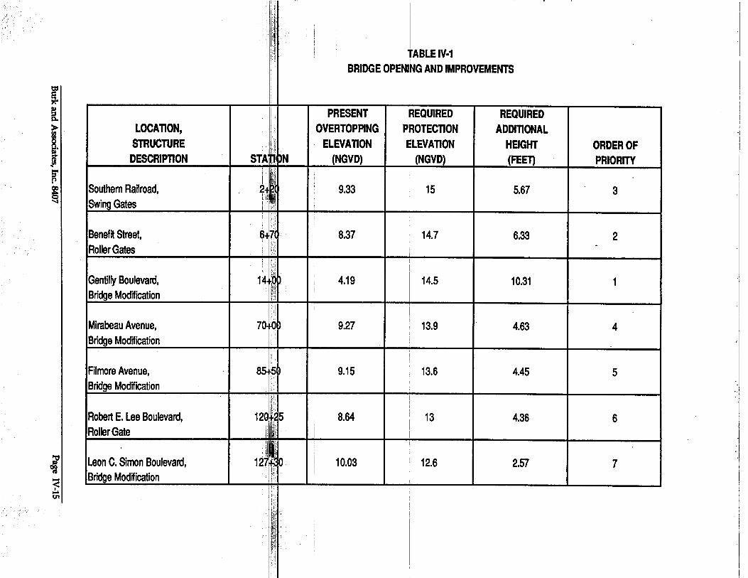
r ~
[ >
~. .... 1l ~ ~ 'I
;p ~
<! ,!. U1
n",
I jiJi i jqi I~li: lill' i' i
:11i i TABLE IV.1 ",I I
BRIDGE OPENI~G AND IMPROVEMENTS
!
PRESENT REQUIRED REQUIRED LOCAT10N, i.1 OVERTOPPING PROTECT10N ADDlT10NAL
i
STRUCTURE tl, ELEVAT10N ELEVAT10N HEIGHT ORDER OF DESCRIPT10N STA ~ bN (NGVD) I (NGVD) (FEET) PRIORITY
i i' ! i '\' i! 'I I j, ~lil Southern Railroad, ~ . .i~'. i 9.33 15 5.67 3
Swing Gates :' ,J I ';:,
BenefR Street, 6-11 8.37 14.7 6.33 2 Roller Gates • • t .
11 ,1 I
i. iii: i Gentilly Boulevard, 14 !Q) I 4.19 14.5 10.31 1 I
. 1111
Bridge Modffication , Ii': 'i I
Mirabeau Avenue, 70 ,O~ 9.27 i 13.9 4.63 4 Bridge Modffication
i I
Filmore Avenue, 85 :5~ 9.15 13.6 4.45 5 Bridge Modffication I·
t!: Robert E.lee Boulevard, 1~Qf.; 5 8.64 13 4.36 6 Roller Gate Ii I!r i
I i' ! I JI I" i
leon C. Simon Boulevard, 127~ 0 10.03 12.6 2.57 7 I Bridge Modffication i I;i'l
i i ~ 'i
I !:\' !
'ihil !
• iili. I
II~ i
Ilil, i il~1 II!I
Iii! i

-----::----:--:-------:--:;---,-,----:-,-------.--- ~-_;_-~-. -----.-- ----;--------:---,-----o----~~~-~-------
London Avenue Canal
. TABLEIV-2
UTILITY RELOCATION SCHEDULE
Station Description
1+23 48"0 Drainage Force Main
6+55 Overhead Power Lines
10+59 Overhead Power Lines
13+08 12"0 Gas Main
14+18 12"0 Water Main
49+88 Pedestrian Foot Bridge
69+35 Pedestrian Foot Bridge
69+44 10"0 Gas Main
Disposition
Remains - Adjust Floodwall around existing pipe
Remains
Remains
Remains - Install Temporary Bypass.
Remains - Install Temporary Bypass_~ __ ~ ___ _
Remains - Install new conc. step
To Be Removed, Replaced with Sidewalk on Bridge
Remains - InStall Temporary Bypass
~- ~.;-'·=~~~mrtemporary ._·~;O'"=.c,,-.~'-'-_:_:~:~Zj!'
70+40 12"0 Water Main
84+91 5"0 Gas- Main
85+00 50"0 Water Main
85+13 Pedestrian Foot Bridge
Burk and Associates, Inc. 8407
Bypass
Remains -- Install Temporary Bypass
Remains - Install Temporary . Bypass
Remains - Install Temporary Bypass
To Be Removed, Replaced with Sidewalk on Bridge
Page IV-16

London Avenue Canal
TABLE IV-2 (continued)
UTILITY RELOCATION SOIEDULE
Station Description Disposition
100+60 Overhead Power Lines Remain
100+66 18-5"0 Telephone Conduits Remains - Provide Split Sleeve Casing through Steel Sheet Pile
101+55 10'0 Steel Siphon Tube Remains - Temporary Removal during Sheet Pile Driving Only
101+64 52"0 Steel Discharge Tube Remains - Temporary Removal during Sheet Pile
-------------~- - ---- - - --- -------- --- - - -- --- - ------------- -- -.. D~ivingOnly---- . - -----"-----------
119+87 Pedestrian Foot Bridge To Be Removed, Replaced with Sidewalk on Bridge
120+49 12"0 Water Main Remains - Install Temporary Bypass
121+10 Overhead Power Lines Remains .---- -----~---
Burk and Associates, Inc. 8407 Page JV-17

~ c::i ~ ~
~ m z Ul 0:
t ~ w ::e .J I- W ~ :::> z z °10 w w Ul m (!)
orIS. ~I ~ to
0 I 0 + 0
ti
0 0 + ...... N
LONDON AVENUE OUTFALL CANAL o o + l"'-I")
300 YR.*
W ~ ::> L5 m ~ -
15 /' 140· ; .................... . 4.5 __ ... ' - ........ ' ... -&. . . . ..•. ~_
L.J ~ w e:::: 0 ~ .J G:.
D.P.S. #4
Wei I-~ e::::m w mw Ow
...... I ......
z
~I w 1 0 0: Z o 0 ::ell.. Ulw w> ~-0«0:
o...Jo + o to ......
. . . '13·5· . :1r ...... , .... ~O.:. °1'3F :RO~OSEO LEVEE)~(':3' '0· T'O' l' ~ ~ ~5. '.. . r= '- .- - - . - 'I. • • .. ... r
· . . · . . 5
---J.----------• • • • • '.' •• V>I •••••••• '.' ••••.• ' •••••• rA '.' _____ ..... ______________ ...r/:I
·1~· ~: "100 YR.* L: EXISTING LEVEE--J 5 . . . . . ._-'-.... '.' ..... 10:. .. ,~.~",:",,:".~~ ... ~.~~.~":":"'.~~.~~.~ .. ~ .•.
~- 1B • N N 10
.:...J N N. a..:...J N
- .------ ~ -9;; X N -' - ~ . - • to _ N . ......
(-)5 . I II mo'o 0... . 'V . 0 . . 10 . . . . . . . . I'!) . 1:'>..... to·· . . . . . . X N' . . . . . . x x...... . • N . 0.J . o
.( -:)1? .: .I.~.I.I . ~ . a.. .
10
,~~;~~ .. b:~£~=-.~~;
o m to (-)11;0
(~).3? :: . I. . . I. -:- . . . . . -:- . . . .
:UJlli (-)45: (-) 41.S
'1' .
tOo... N
.1")
,~~--: ~~~::::.~.~-: -
: ", .: . . '.: ... ~ .. . .
* FOR ELEVATIONS SEE PLATE 1I-5
...... . ~ .
·x lO. ~.
in~: 00...· 10 . ......
...
--~--~~~;:;.: ---------
'in "-
. I") 10 . . . .•. . .'. ·N· (-)5 ...........
,XN .J
00... ''V ·v '1")
(-)15 '.0 ••••• : ••••• °
0' ••••• ,0- •••••••••
(-)25 ___________ ._._~c~~:.::-::::::.:..-:::-~." _ .•.. " __ .-::_~. __ .=~~~.::;.~r-::-"~... ~~A
· . . . (-)35 • ............................. o •••• "0 • · . . . .
, , (~)45
• • • • '0' ••••• 00 ••• • 0° .' ......... . • • 0° •• •• '0 ••• • ••• '0' ••••• 00 ••••• '0 •••••• 0° •••••• " " " • " "." " ••• " • "" " " " ." • " ••
-0 10 20 30 40 50
LONDON AVENUE CANAL FLOODWALLS AND LEVEES GENERAL DESIGN MEMORANDUM
60 70 .80 90
PROPOSEO-FLOODWALLS . AND LEVEES
WEST SIDE·
100 110 120 130
. BOARD· OF COMMISSIONERS ORLEANS LEVEE BOARD
140 150 160
Burk & ·Associates, Inc .
OU3CONTRACT NO. 2049-02691JOB NO. 84071 PLATE IV-1

~r
_~:s:'':'R-~~=~~---=-_:
~ ci ~
ti ~
Z (D
a:: 1= ~ w
:c lL. -l I- W I-::> Z Z °10 w w (/) (D (!)
0;3S
, o~'I'f 0 + 0
15 15.0
10
.( ~ ).5. .:.1. . . 1.1 . ~ . ~
o IX)
~~).1? .: .1. ~; 1.1. ~. Q.. .
-·25 .
u-, to It)
~c:"'-·C~·:·· -·"'"·=I··~·"":
~ w. (/) > W W < ~ . . a:: ::> W 0 W ~ W I-~
~ ~ mw - -l 0 Ow l
(/)L ~ @5ffim
g 1 ::;; ;;: 8 I . "" ...J
\. I 1'\" II I ~ I '\ " LONDON AVENUE OUTFALL CANAL gj O.P.S.
81 ~ _ #4 o o + ..-N
+ ,...... t") ......
. o ~
·03 U
Z Zo o~ w-l(/)
......
w a:: o ::c (/)w w> ~-oc::(a::
0...J0
+ o (0 ......
wi ~U·
Z o Q..
300 YR.* . 11" ....... _ .... :O~. ~~ .P~~:'~S~~ .L~E.E.~. .... ( .......... ~5. .... _ ...........•..... '14.0' ............................ '13:5" . "Ii' 13.0 __ 13.0 1~ 1-3.0 TO 17.5
rL11111 t ~ I.I~~ : ._11111 r: III1I .: 1IIII : 11111 11 111)1· II .1111.1 IIIII III 11111 . .11111 IlL·»· . ---
* * ........ _~ ~IST!: lEVE~ __ _
..r- --:---:
:~- ..- --~--- .. - - -- . ;..~---:----• - N ~ ~
. m (',/ Q.. 10 . 10 .. n. . rf). . . . . .. . X c,r ············X N .(!) N ~
Xx Z 0 -l Ln Q... • - . I- (0 Q.. o· o 0 (/) (',/ Il) t") ~ X ,..) r-to ...... w ......,-
- , 11111 I (-) 18.0
~-!-~_~ 41" ',. • 0' ••
.~ --('\I.~
If) . I •• J • :X<"J N • -l
OQ.. ....... ·Ill ......
It) 0---~ It) .
·x N ·· N·
• -l o Q... m . ,...... ......
':c~:-'-'
-.,..
..* . ·V.I-.· •••••••••••••••••••••
........ N
.. t")
5
~~--~I- : .. .. ( -)5 X (!) . . . . z···· 01-CX)(/) (Ox
W - .... (·:-)1~
(-) 19.0
(-)25 .c .. C __ ,~~ .. -c".. -.c~-=77iiif::-'::"~:':~'>':-.'- ---.,,-~-~ .. - -- I
. . . . . (-)35 • • • • • • .:. • • • • • ~. • • • • • '0 '. • • • • '.' • • '. • • : • • • • • '.' • - .. • • ~. • • • • • • .. • •
... .(-)35 : ,\:::ry-2T.O--~----·-. . . . . . . • • • 0' ' .••• ", : .. • • • • • 0° ••••• : • " .••• 0" • • • • \ • 0" .; : 0"
(-)45 . t-) 41.$ . . . . '0' ••• . ....... '.' ..
o 10 20 30 40 50
.' " .'
LONDON AVENUE CANAL FLOODWALLSAND LEVEES GENERAL. DESIGN MEMORANDUM
·60
.... 0' •
70 80 90
·PROPOSED FLOODWALLS AND LEVEES
EAST SIDE·
100 110
. . . * .. FOR ELEVATIONS SEE
. . .. . . . . . .... ~~~. 1~~5. . . . ... . . . .. .. . . . . . { .. )4~
120
** REMOVED FROM- EAST SIDE,. . DPS #4 TO ROST; E. LEE .
130 . 140 150 160
.. BOARD OF COMMISSIONERS ORLEANS LEVEE BOARD
Burk & Associates, Inc. ""'" In.JIIiuIMn.~ .........
.." 0..-... IftIIIaDa
OlB CONTRACT NO. 2049-0269 1 JOB NO. 84071 PLATE IV-2

IMPROVEMENT LENGTH PILE PILE VERTICAL " OR OF CUT OFF TIP PILE UNIT CONSTRUCTION
STATION TO STATION LOCATION STRUCTURE STRUCTURE ELEVATION ELEVATION LENGTH QUANTllY UNIT COST ($) COST ($) PHASE
0+00 - 2+10 DPSII3 FLOODWALL - - - - - - - - LUMP SUM - - - - 111,000.00 II
2+10 - 2+38 SOUTHERN R.R. FLOOD GATE - - - - - - - - LUMP SUM - - - - 265,000.00 . I
2+38 - 6+60' WEST PZ 40 422' 15.0 -41.5 '56.5' 23,843 SQ. Fr. 23.00 . 548,389.00 II
6+60 - 6+90 BENEFIT ST. FLOOD GATE - - - - - - - -- LUMP SUM - - - - 275,000.00 I
6+90 - 13+10 WEST PLZ 25 620' 14.5 -25.0 39.5' 24,490 SQ. FT. 16.00 391,840.00 II ~ 13+10 - 14+10 GENTILLY BLVD. MODIFY BRIDGE - - - - - - - - LUMP SUM - - - - 500,000.00 I
14+10 - 21+00 WEST PLZ 25 690' 14.0 -25.0 39.0' 26,910 SQ. FT. 16.00 430,560.00 II
0+00 - 21+00 EAST & WEST MISCELLANEOUS - - - - - - - - LUMP SUM - - .- - 113,000.00 II
21+00 - 37+00 WEST PZ 22 1,600' 14.0 -11.0 25.0' 40,000 SQ. FT. 14.00 560,000.00 I
21+00 - 37+00 EAST & WEST MISCEllANEOUS - - - - - - - - LUMP SUM - - - - 27,000.00 I - -----"-. .. .. - --._. _. . . --- --- . .... --~ ----------- - ---- -- -----------------_. _. '-. ........ _._--
-------- -- - r
37+00 - 69+60 WEST PLZ 25 3,260' 14.0 -27.0 41.0' 133,660 SQ. FT. 16.00 2,138,560.00 II
69+60 - 70+30 MIRABEAU AVE. MODIFY BRIDGE - - - - - - - - LUMP SUM - - - - 457,000.00 I' ..
.70+30 - 85+35 WEST PLZ 25 1,505' 14.0 -27.0 41.0' 61,705 SQ. FT. 16.00 987,280.00 II
- ---- - - --- 37+00 - 85+35 EAST & WEST MISCELLANEOUS - - - - - - - - .'. LUMP SUM - - - - 505,000.00 II ....
R ... ..,,"lIJ:; 85+70 FIr MORE AVE. MODIFY BRIDGE 361,000.00 ..
I '. '~-.".~:(~.;:--~~ '-.::~~;: -':::'-
LUMP SUM ... . __ .. -~ --_. ...
-" .. ---- .-. .
... • _ •• __ "_. __ • -4-'~ •• c. ....•.. . .•.• :.,.: ;:...;., ,..- ~ ~':-'-':.- ., ::'c-n';: 'riCO' '''''''._.- . ~"c;.;'j;~;;;.iii. ........ ~~'''.... ::C",' ... :'"'85 .... 70. 120+10 WEST ""PI..Z': ':l~ ., -, '''),4+U 1,).0: -~"t.u ,)/.0. . ... . '."~·"'jV~v .. .... .' n;r.of)' .
"-,v", ,"'''''''' .•.... =... . ,':. ':"'. ,·" ..... ·"::··c,,;c,,:' :' ', .......
85+35 - 120+10 EAST & WEST MISCEllANEOUS - - - - - - - - LUMP SUM - - - - 363,000.00 . I
120+10 - 120+40 ~OBT. E. LEE BLVD. FLOOD GATE - - - - - - - - LUMP SUM - - - - 325,000.00 t
120+40 - 127+20 WEST LEVEE EMBANK. 680' - - - - - - 15,500 CU; YO~ 12.00 186,000.00 I
127+20 - 127+40 L C. SIMON BLVD. MODIFY BRIDGE - - - - - - - - LUMP SUM - - - - 153,000.00 I
127+40 - 160+00 EAST & WEST LEVEE EMBANK. 3,260' - - - - - - 75,000. CU. YO. 12.00 900,000.00 I
ALL ELEVATIONS ARE NGVD
. Burk & Associates, InC. ,;. '. SUMMARY OF PROPOSED
BOARD OF COMMISSIONERS ......
LONDON AVENUE CANAL 'FLOODWALLS AND LEVEES' ORLEANS LEVEE BOARD ~ a Plamaen a EDUroDmeDtal l!o1eutiatll '. IMPROVEMENTS He'; OrleaDa, LouIIdaDa
GENERAL DESIGN MEMORAN'DUM .. .' .
OlB· CONTRACT NO. 2049-0269 JOB NO. 8407 PLATE N-3 (WESTSIDE AND CROSSINGS)
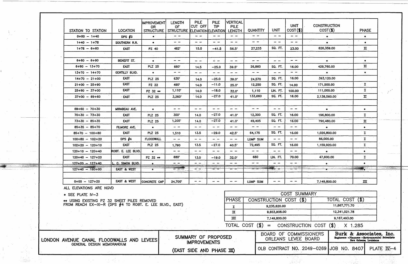
:.:.~-~,\. ==->' ,--~~-
IMPROVEMENT LENGTH ~ PILE PILE VERTICAL OR OF CUT OFF TIP PILE
LOCATION I STRUCTURE STRUCTURE LEVATION ELEVATION LENGTH I QUANTIlY STATION TO STATION
0+00 - 1+40 OPS 13 • 1+40 - 1+78 SOUTHERN R.R. • 1+78 - 6+60 EAST PZ 40 482' 15.0 -41.5 56.5' 27,233
6+60 - 6+90 BENEFIT ST. • 6+90 - 13+70 EAST PLZ 25 680' 14.5 -25.0 39.5' 26,860
13+70 - 14+70 GENTILLY BLVD. • 14+70 - 21+00 EAST PLZ 25 630' 14.0 ..,..25.0 39.0' 24,570
21+00 - 25+90 EAST PZ 22 490' 14.0 -11.0 25.0' 12,250
25+90 - 37+00 EAST PZ 32 •• 1,110' 14.0 -18 .. 0 32.0' 1,110
37+00 ..,.. 69+60 . EAST PLZ· 25 3,260' 14.0 -27.0 . I 41.0' 133,660
69+60 - 70+30 I MIRABEAU AVE. •
UNIT UNIT I COST ($)
SQ. FT. 23.00
SQ. FT. 16.00
SQ. FT. 16.00
SQ. FT. '14.00
UN. FT. 100.00
SQ. FT. 16.00
CONSTRUCTION COST ($)
• •
626,359.00
• 429,760.00
• 393,120.00
171,500.00
. 111,000.00
2; 138,560.00
•
PHASE
• • II
• II
•
I
I
II
• 70+30 - 73+30 EAST PLZ 25 . 300' 41.0' 12,300 . 196,800.00 I
73+30 - 85+35 EAST PLZ 25 - ------',205' 41.0'49:405-- 790,4tfo.oo-------:II
85+35 - 85+70 FILMORE AVE. . • • • 85+ 70 ~ 100+80 EAST PLZ 25 1,510 13.5 -29.0 42.5' 64,175 SQ. FT. 16.00 1,026,800.00 I
100+80 - 102+20 CPS 14 I FLOOCWALL LUMP SUM 86,000.00 I
102+20 - 120+10 EAST PLZ 25 1,790 13.5 -27.0 40.5' 72,495 SQ. FT. 16.00 1,159,920.00 I
120+ 1 0- 120+40 ROBT. E. -LEE BLVD. • • • 120+40 - 127+20 EAST PZ 32 .. 680' 13.0 -19.0 32.0' 680 I UN. FT. 70.00 47,600.00 I
~ I ~; SIMON BLVD. 1?7./.?n _ 1?7./.4n .-::"'::~"':."!:;":..~",,: ,L-" • • • -
av .1 !c WEST I -. :r::-: ":""7 __ 1_ -. -I .- -1-- ·-1 ----H. rT!§o~;.I--"-"~:~=';-r"· -.'-'-~ -.'.. -·l-;o·,.,;"~l:'''~·';,'~"c:.c::l .. ~-:--.:~::~-'=-;::-~::~".:.:..:~I.~ --EAST; ----------
0+00 - 127+20 EAST &: WEST ICONCRETE CAP I 24,700' LUMP SUM 7,149,800.00 m ALL ELEVATIONS ARE NGVD
* SEE PLATE IV-3
** USING EXISTING PZ 32 SHEET PILES. REMOVED
COST SUMMARY PHASE I CONSTRUCTION COST ($) TOTAL COST {$)
FROM REACH EX-XI-R (DPS #4 TO ROST. E. LEE BLVD., EAST) I 9,235,620.00 11,867,771.70
LONDON AVENUE CANAL FLOODWALLS AND LEVEES GENERAL DESIGN MEMORANDUM
II 9,603,908.00 12,341,021.78
m 7,149,800.00 9,187,493.00
TOTAL COST ($). = CONSTRUCTION COST ($) X 1.285
SUMMARY OF PROPOSED IMPROVEMENTS
(EAST SIDE AND PHASE lIl)
BOARD OF' COMMISSIONERS ORLEANS lEVEE BOARD
Burk & Associates, Inc. IqtDeen 0 ~ 0 JzmroDmental SoleIlUsta
x." ()r1eau, LoutIdaDa
OlB CONTRACT NO. 2049-02691JOB NO .. 84071 PLATE' E[-4

2O';!:.
+20 10'
It EXISTING LEVEE
+20 . . . . . . . . . . . . . '1' . . . I· . . . . .1; . . . . . . . . . . . . . . . . . . . . . . . . . . . . • . --'"-LEVEE ' .....
EL 13.0 . El.13.0 (FREEB'OARD) .-#> -..;. -1--- --'--' . ~. \]
IV: 3H ---.... ____ ___ ~V:3H --.--. - :- -: ·.-EL11·P(100YR.) -- - ' __ '_~'":,,,_._ .......... ~. . . . . . __ -- __ ""'-____ ~AVAILABLE FOR BORROW _________ --:_._ . ..-........... '" ~----.. EL 10 ., : ........ "'.". . ......... ,..... , .. ,., ..... . ......... . .....
o o
-20
+20
120+00 TO 127+00 (WEST)
£ EXISTING r. H
- 3S~-- _llEVEE:---~' -
""'"- .........
........ '------------20
10' I +20
, , .. , ... , , ,. ~t~£O' ..... t ...... ~ ·E~. ;2.'4' (~R~~B~~R~)' . , ..... , . , . . . . . .. .
--'==:±:==' . .=...sz.:.EL10.4(100YR.) ,: ~: _--.,.'-
o
7----------- ---- ----, o ---- __ ----tv:;; !~ -~.~ ~~A~~~!LE fOR
-20
LONDON AVENUE CANAL FLOODWALLS AND LEVEES GENERAL DESIGN MEMORANDUM
" . . . .
127+00 TO- 152+50 (WEST)
lYPICAL LEVEE SECTIONS . _ STA.120+00 TO STA. 152+50
WEST SIDE
.:.:.::~-=-~~..:---:: '-.; •• :~:---
-- ........ ----''----- -20
. .. . . .
BOARD OF COMMISSIONERS ORLEANS LEVEE BOARD
Burk &, Associates, Inc. Eng:\neen 0 Pl.e.nnen 0 bnironmental Sclent1ats
Ne... Orleam, Louisiana:
OLB CONTRACT NO. 2049-0269 1 JOB NO. 84071 PLATE N-5

} I~ 35:±. TO 100'.t.. •
10' +20 . LEVEE EL «EXISTING
• .••.• .. I . . . . . . . . . . . I .' ." ........ +20 . .. ......... .
EL. 4.0 EL.ZO ~ -'-~ ___ -D.------. _______ ,/,// ~~~AVAILABLE FOR BORROW
..................... _. _ .. _._._._. ____________ " EL.4.0 --_ . . . . . . . . . . . . . . . . . . . EL.1.0 --. . . . .. ...... .' . . . . . '. . :--:- -::- ~ __ :....:... 0 ----20
-20 . . . . . . . . . . .. . . .. .. . . . . . . .. . .' . . . . . . . . . .. . . .. . .. .. .. .. . '. . .. ... ~ .. .. .. .. .. .. . ". . . . . .. . . .. . .. .. .. .. .. .. . .. .. .. .. .. . . .. . .. . .. .. .. .. .. .- . ...
__ ~~~~~...G'.~':~~~:~~'~. ~'-'
152+5010 LAKE (WEST) (TRANSITION)
_': '-;,-~<--~:': ;~;:;~~~--=--. '-' .. :';-.:~-:-~~~-;:~~~~~~~- _--':':::-,:::=~":"':-:,,":-"-7~--- - .. ~~:;~.~~~~~ '--~~:~;---
--"""'- """'-'- """'----
.. ,=,,~ .. :~cc_;:'~":::;::1 :'--~~
BOARD OF COMMISSIONERS I' . Burk & Associates, Inc. 'ORLEANS LEVEE BOARD Engineera opt.annera o!!lniromnental Scient1aU
. He'll' Orleana, lou1s1ana 1YPICAL LEVEE' SECTIONS
.',-" STA. 152+50.. TO LAKE LONDON AVENUE CANAL FLOODWALLS AND LEVEES GENERAL DESIGN MEMORANDUM WEST SIDE DLB CONTRACT NO. 2049-0269 I JOB NO. 84071 PLATE N-6

-~;k~:'~~ __
-
10:±. 't
't EXISTING ~ LEVEE --t i,
.' . I J-.-.!Q-+20 ... , . . . . . . . . . . . . . . . . . . . . . . . . . . . ................... \: . I. .. :-'1 . . . . . . . . . . . . . . . . . . . . . .. . HO.
=-,.==:==:==:' : E~.12.4 :(FREE',BOAR~) :~~:3C:_: ==::=:::==:-EL 10.4 (100 YR) ~ _ - --_ - -' . ---- ----AVAILABLE FOR BORROW _____ ---_---- --__
o --~ IV:3H .---.;: • • . • . . . • • • .•.••• _ ._ r--:" ••.....•••••.•••.••••••••••..••••••.• , ••••••••...•.... ----,/.~".
o __ 0-__ ~ ____ ._.----.. ___ _
/ ;"".
/. ;"" ....... -----------.
-:40 ....... - .......... .
+20
. ~-~:::=.:';:-~.-' .. ::-"":~~:::~- ~ .... -;=;......-~'-
-------_ ....... ,/ -20
:~';;~~3~~~~" .. ?--;",- .....
-20 • ............................................... _ ................... 0 ..... 0 ............... " " " " 0 " ... " _ ...... 0 .. ". 0 " " .... "
127 +00 TO 152+50 (EAST)
10':i:. TO 50:±. " I 1- +20 '2 EXISTING . . . . .
. . . . •. • . . .. LEVEE .... 1
1
• • ' .. 1' .. ' . . . . . . ~;.~~~~~.5 I. 31' ... ;1 . . .. . I 41' . - . IV: 3H __ ... . .. . ~ '1 . . .
--AVAILABLE FOR -......:.....~. -----_-- EL.6.0
BORROW _::.::-~:--~ \~-__ ..:E=L=.=6=.O====.--EL. 4.0 .:.-- _ -= -- ~. ' ..•.. J .••••• ·.~"iiiAo~j-' ..... L:;'.:::.::~ .. - .'~ . ,.~.::.c~~· ~ ••. !JiiIE··~·c:· '. :'cc:"" .•.. :0"!P;o..';;,:;"· .. --. - .=-. ~' ___ '.~' _.""'¥ii!. Jji( -- v = :> !.:.:: 4.
0 l
152+50 TO LAKE (EAST) TRANSITION
-20
Burk & Associates, Inc. LONDON AVENUE CANAL FlOODWALlSAND LEVEES
. GENERAL DESIGt-t· MEMORANDUM
lYPICAl lEVEE' SECTIONS STA. 127+00 TO LAKE
EASTSIDE
BOARD OF· COMMISSIONERS ORLEANS lEVEE BOARD Engineen o'l'laime:rll 0 Enviromnental SclentlstB
NeT Orleans, Louisiana
OlB CONTRACT NO. 2049~o2691 JOB NO. 8407 PLATE J'iI.-7

8' 2' 2'~
.. r..~b~NgF WAY. . . . . . . . .. . 11 .. ELEV~~~ ." ................... ELEV· .'8" .......... : . 1'.. ...... . .... ~~b~~NgF WAY~ 10
I (n r EXISTING SHEET PILE & CAP , EXISTING SHEET. PILE & CAP ---i n: I . / ELEV "c:' / LJ· I !! r . '·1
10
. b --- '. IF--_ .;--- EXISTING LEVEE EXISTING LEVEE~ _:Ir o . _~~.~L..,..~-:-:-:~ ..... : .......... ·11·· ... ~'-:-:--::\..-:." ............................ ·.:-:1 .. ~l· ... ·lo r· ." -----. /-" _ " '-,- ./" '- ./ " '-,- / " ........-
u
-10 . , ............................. ·11· ·/·1· ............... . U
TYPICAL SECTION SOUTHERN R.R. TO ROBERT E. LEE BLVD.
-- ---- -- ----EWE-Sr-5IDE-j- - ------ -- -
LOCATION
ELEV. -A- ELEV.-ff TOP -OF 100 YEAR SHEET STORM
PILE ELEV~ ELEV.
13.0 4"'l n
ELEV -r: WEST LEVEE ELEV.
15.0 *** J::.n
ELEV. -rr EAST
LEVEE ELEV.
12.6 J::.n
**DPS#3 - S. RAILROAD I 15.0 ~;;_~c:':~,., .. ~"::,.".,;,;,~,",,~~;;.~;;-J;-:,:;;~_ I . :.~~&~~i'-'.i~~.l:.¥~-:;'i~.~:·-.~"~~"t1,j'~,,.,:::,"._ - I:_~_~:~'" "..o~~--""<*,~c, '-,:;-.='nf-'·-I'----~~--"
u , c . • • - - - =.--=--=-=----=--.~ •
12.0 5.0 -- -·5:0 12.0 7.0 7.0
GENTILLY - STA.--2TtO-0------14.()-STA 21 +00 - STA. 37+00 14.0
----_._--
-
. .............. -10
TYPICAL SECTION DPS #3 TO DPS #4
-------R-Q8 ERr E. LEE---BbVt)-. -TO -b~Q N--G.- £IM 0 N B LVg. ,----(EAST SIDE)
8'
S7 .;--ELEV ... P;' EXISTING
". ~ELEV"8" . . . . . ....... RIGHT OF WAY~ 10
EXISTING SHEET PILE . -- - -- - . . . 1·- --
1/ ELEV. "0" I
._-_ ~ ~ =-~=-~ ..... -i-: =..i;;~7 - ~_~ __ ~ _ .. .:....:::::=:.:-~ .. -~~ ~=-... ~ - _.::.'=~_>_
-~) . . . . . . . . . .. ·/1 .... J 0
12.0 7.0 7.0 12.0 6.0 6.0
./ I I EXISTING LEVEE--V'/ 1/ STA. 37+00 - STA. 58+00 14.0
STA. 58+00 - MIRABEAU 14.0 MIRABEAU - FILMORE 14.0 12.0 6.0 6.0
.11.5 6.0 6.0 11.5 6.0 . 5.0
FILMORE - DPS#4 13.5 DPS#4 - ROBERT E. LEE 13.5 ROBERT E. LEE - LC. SIMON 13.0 11 .0 13.0 *** 5.5
* ELEV. "f( = ELEV. "B" +2' FREEBOARD MINIMUM. ** SEE DPS #3 DETAILS
*** NO SHEET PILES ON WEST SIDE
LONDON AVENUE CANAL FLOODWALLS AND LEVEES GENERAL DESIGN MEMORANDUM
lYPICAL SECTIONS SHEEr PILE I-WALLS
./
./ /1 ././ II
-10
TYPICAL SECTION.· DPS #4 TO ROBERT E. LEE BLVD.
. (EAST. SIDE)
BOARD OF COMMISSIONERS ORLEANS LEVEE BOARD
Burk & Associates, Inc. EnpneeJ'II 0 PlaJiDe1'II 0 .!D-vfronmenteJ SoIenUaU
HeY. 0rleaD8, LouUtaDa
OLB CONTRACT NO.' 2049-0269 1 JOB NO. 84071 PLATE m: ..... a .. . .

-
" . ..:...70'.. 4 '8;}G' (:J:) __ I 25' !!j' --
7! q%' 7'- 2%' 7'· -Z%' (0'-/0%' 8?:. /;:1 4'-<0" 4Jl1~' 3,1-(;· 4.J1I~ I 4~O' /fi. z-a I WR . ..,J~Track I I Z-8
__ . <08'- Q. 1%;;' (:t) II~O. -4~O'(t ~5'.. 0" . -- ~'-Q.'7J' (t)_ .. - ., Z5'-O· 4~O'(t) 4" A/. Roil Po~' @"'<;Ie (T'{p.)
I I r ! I .~ k-ttm33MoKD
I-Sidewolk __ ' - - . ~~ SidewoJ_k~~ I;V LPorapel Wall .. _
rli Concrele Meo'/on_~ (1) 7" Cos I inp}oce Slob 1\ V· '" t eL 7.70)'/6:V.D.~ L.....1 , ~ .' _"! ~ ', ... _. ..... &.. Ed ... , •• a..
y .... .. 'Pv 4> .... .oI!o. ~E'
,...., ,...., . S/eeL_ChQ'nneLr:>iophrogm I ' .: (15 [.33.3 -#)-CTl{p.)
- Concre#e-Slob- '~ll;:J~··l.£.:· ... ~ ... ..--
_ Concre Ie. cap-z..-j . <:t-
2'8'x3'-o' ~ ~ ~ ~ ~ ~ , ~ f. T T T ~ Itszo¢ Sleel Pipe.P;}ell,p.)
Ld d.. r+ rh r+ , it n~ d d· ,-h rt, Ccjn'cre"e:'Cap:~Q:)(3G" 11!1! "I! I/! I! I! I! I! I! I I I I IZ'CP Slee'- P.ip.eJ>ile (TIIP·) ! 4 It Ii 'i 4' J ! 4 liP(DeSi9nloadE40Ton~/PiJe)
., 7.EquaJ Spoces@ 4'-O'(±) c/c ./
J ~ Lf 4 T ~ LJ' Pile Tip-l.levatian" - BO.OO
SOUTHERN RAILROAD BRIDGE
IE. 5teel G'-rder8 @ ~~o"(:n c/c (21 WF5S") 12 5teeT.PiJes @G'-O" (t:) c/o
MIRA BEAU AVE. BRIDGE
Bij : . _,3 B'- 0" ~d :
. , , " l!'C· I' .z G- 9 <;S'ttl . 4-0 13' G' _1" G' "'-O'~ 8 94'- 0'
35'..4'
__ 25'- S!Js' (±) ! ,," . 4"A,I- ROlTPoslA.1 Sioewa;k·. Sidewalk parapet Wall 2<>" . .~ - .----... Z8'- 0' .
S f I R
-J _, _____ 20'-So/a'(:J:)' W ----.@ 4± o/ctTl{p.) •. Canc.Med,an Sidewalk _.- - Sidewalk ee 01 .. EL64CJAL6YD " . _(:J~p,'- Side~1k.- ""---- . ? Ca.' on place Slab
eL8.37 N6.V.D. Sleel Pas! EI. 5 . .39 NG.V.D. Parapet (Tl.{p,) Concrete --Concrete' Wall
Diophr0
9rT> Diophrogm
._zo"s/ee/_Beom C@J;;5..4~e-3><3>< 511G' Con~refe ,Cop ,-- . [TIIP') H. .. Bearn- @ 2~J'(:t) (TU-D~) . AngJes(T,{p-i 30 x,sG W f L 1 Concre1e . 11- . - a er eve cop so' Wide
Timber B"x 12' IZ'¢ Sfeel Pipe Pile -, . ' C~J . _, J (CQPocit'1 per'piJe- Piles can not be seen.
14"¢ T,-mber Pile (50' long) 8 Bfee.l..Eiz:r:J~r.Jj ~ 4~E:t) o/c (18WFZZ"') ~ Design load .. 35Tons) (TC(p.) '? SleeT Plies @ 5'-O"(±) c/c.- PIle Tip Elevation ~ -80_00 ROBERT E. LEE BLVD. BRIDGE
FILMORE AVE_ BRIDGE
71~ 0'
1~0' - , , ,5'-0" G9~0" 3~/O.(:t) . • I I/!O" '~~
2.'?! 7 -(z) Z7: ?-(:t) . 5!.0·
BENEFIT 5T. BRIDGE ·1 I ~5idewo/k_ - - .
_ /34'-:3" 19'1 ~ (. I' .-?" Cas! in f)lace Slob "0,""'" "- -·~I;;;~L_c'I,,":I~, .-:.: .. """,-:~<,.::,: ''-.'.' .. ' -'2.,'.1'- ",.,,,"" '. "::,_ "> ·0.... "'" •• ;.;, • .,., --':,:'; ,~'"::':':''''''~ , __ ,. ",.,', "" '.._ .. "",,,' '.-,. ""--:.'.·c;O~C:, -'.,.,:';,.,' __ './~J~:'c::;I.:: =_~_.c '.' . t ",.~ d'''_'
d;;p}:~~~;;~~on sl.aewaJX]),~,~Jas2~&(ef ·_"A;.:.~I.~",;-~:;· .' .. , u~I~'5"-cr _~1'-.1:)", 'le3:'S"1 --c. 21~O" ;~5,ul'" ;U.,., c:~ .. > T f·l "1 "'T'" -l-- u uuT 1 "-TT
,~ ,~r1Sidewalk }z-1~0" 1'!1!lT... rr-:-l~O' Sfdewolk h ill c;oncre/~em C I (\I -, -. , DIO hra onere e -tl,. r 1!.4Ye' (Z) Slab . I! ' " I /' Cone. Meehan I . . P(71.{f.) r :t r ~ + + 1+' -t rt rt. r -11 -+- ,+ ,f, M + -h .h Cap • . ,-' I £l4.19 AL6V.D ." I : , ! " ! ' ! I 1 . IT rr TIT! ! II - ~I' --- ---- '""i~ ~': , I: ' ': 'I 'i ~i! ~I! 1\ I! ' t Ii
'--c' Z-Sh (Tc .~·I .>1 -I :·.·IfTIj· I'j:~(~"I.".'I" I~· __ h~I'·'.:I·, T~.1.,I'·;l:i~ ~.-I:I"·I.·I···:I'~.r.:~~~{ .J:I 'a~~~$~~~~(Tqp.) I , 41 +' ! 4' +. ~I II + ! ~ t" 'S/~;~eS~~r:, . , • oes '1P,~ ..Dl:h .r'ii:'h,\ ~ ~ -zn " ~ ,~ II!" S feel Beam ' t· (T'fp.)
-, I . . -::-L 4 x.B x'/z (Tgp.) "'iiil -=- SZ c f-G '"1C' _ • ," , • _ " ,_ Pile Tip ~~ .l r ~ . .,. 1·~r .s1 flo '" ' " "I. . I t\I ,I '( 1 li) (Tl{p.) 12. sleel GiraerS @ G-3 (±) c/c, u •• _. , Elev.-=-?5.00
i! "'-Concrete Cop l! Floor Beam/ 11 . 1I.Ji 19 Steel PIles @. oS'-.10· (:!:) c/c _. -,-, E IV ~ .. Q -, CO
III '/ 24'@B'?*(Tl.{p')'!I·lcl·PLAT-9 I : :i.l 115\~~]~~n~7i-p.)· LEON C. SIMON BLVD. BRIDGE : e-Z'-l· : -Z-Z'-1~. II --IS!:'?%· II -I8'-4re: I . I(
:. Ii. r) I! 1 : 'or, " 1 C- I I . l) §,. 1 ' I' J " I 1 .,' I -H 1 b ' --:. E ·1 . 'I . . ~. _ IT' I rtl ib rt I j ..l. 1 ,1 :, . r~ . ..1-. . i rh rh: r+: JjJ w. . . 1 I !I i lU 1 lW. i,! m I·! II I· III
I . I 4J ~ . 1jJ'1}J ljJ 't'. . j 9 Pile Fooflng 12. P,-Je Foofin9 S Pile Fooling Ie Pr"/e Fooling 9 PIJeJooiin9_
GENTILLY BLVD. BRIDGE No/e =- AJIPiles ort?-'!S' long -;'NO~5 ·~·-:n1!:!ber: Pl"le.3 ,-_ , Pile copo cdC{: 1570nJS ,Pile np.£levQhon: - '?8.QO
LONDON AVE. CANAL FLOODWALLS AND LEVEES GENERAL DESIGN MEMO,RANDUM
ORLEANS LEVEE BOARD CONTRACT NO_2049 -0269
BOARD OF LEVEE COMMISSIONERS_ ORLEANS LEVEE_ BOARD_ _n:
REV I Do\Tt. -Burk & Associates, Inc. Engineen • Plannen • Environmental Scientists
New Orleans. Louisiana
EXISTING BRIDGES
TYPICAL SECTIONS
~~ ~~
I~ le407~--~~~~----~ ~
fUOO __
f-
- ~'.'~r-
I-~

b -, -'
0) I
-(fl"o ·~I~C
l{\
f-:-
.... __ ~ ____________________ ==~ ____________ -:== ____ ~ ____________ ~::~~==S~5~~~~~.~::::::====::::::::==::::::==::~~~~::::~~;:~::r::J~~::=iI-' 31'- ,:3-~o- ""-2~'G-
:r£:
II! .1
m
7'
,
yupper-HiDge
=--:-
, I"" ...D ~514'GX:' , '. ::s ri w,,' x 12' .~ ,,-~ .".~ : Ii tHfn""
['Top of Go'e .~. . ",T I ~ : ~~ I 'r • r ..., ,'; WIOx.".) ri\!!X4+- ~ i ri%x5,<- JiJ!,xl3~'2. Tl' ';.---r-Skin R.~ -<i (Tqp.) • ! (T q p.) 1 J
I I' U- I II : ,. I " II . I D ,
I I I II R. %x5v D Jl.l£'''2f-.-"1 ' Ir II' I , :, . ; II In D I H Ii i'e.1S~" !-i I : !H:..,nge, II, a II (""up.)~ <-' II II , ': d..J.::1
I , I, ~, '~~_ ~I
Ii III
·1
. ~ n n . • W 14x30') 'LL .... R II III.JL--' I II I.. ,b Iii L ~
" ....II...-====~--·111 II! ill- ---1======--
7 -~ @-.. - /'-111;"" _ i .10 5poces @ Z!'G" - Z5'-0" 1~ e' i 51'· (0-
i e~5Y2"
1 1~!?-
Tzio I /I"
Lower Hinge FLOOD SIDE ELEVATION •
~t 'J' ".: -;;. L <1 x 4 x }2 · .. ·6~ .', ".:-~ PROTECTED SIDE I ---- . "
L 8x4x VZ~ <t>~" "'~4 ~ :-'-- Qo_-' .-. . Cut Blots in~x lq~
PROTECTED SIDE FLOOD SIDE
- W 14XeG.~ ~ . \\l
k I I . f!!lf! x 13%
~
~-0"c cr-'
-' I
li%x5 Ii !lzx<;t0 If' ~
- w.)<;txao 0 .~' -. ---,-,---'-~
-~==--------,~
SECTION ® (Scale:. "%.··/~O·)
r 'j ~f:: <,;tf:~oJ,~;,:::~" i~4g;:o::.~~e~1 F
_,.-_::_'::~;:-::-':;"':::'i.~§-=~i:~~:..:;t .... ~~_:..-;;:~~{~~..::~.~-.-.:,'-' ~-: ~:f~ .-l""In,...·q.~~_S)~~ __ .______ .!!!!lL -- - ~~~:;:~~~~~ -'~~~~;H~~_c' ·' . ." .. 'C"" -.-•. ., ... ~ . '''·':.''':,,=::.-'~=--~~I#
-r li:~~~=====\:=-===--~~;i 1Je x 4 .cTl(p.).'~~.:._
J"'" Drain Holes • b~f}L'_' ".-:' . W 14x 30 6: W 14 x ~G. ___ . __ _
W 14 X30..;.-2[ t ¥ex ~-; 0/. W:'h ;Q:O. 10 "";/ depth of hollom w ~hQpe8 (Tilp.)
FLOOD SIDE SECTION ®
v BQr I~x lYe
'-'" _JiYe~s7 "\..,l Yzx J8%
PLATE IV-10
... , ..... ............. .. Burk & Associates, Inc. Engineen • Planners. Environmental Scientists
New Orleans. Louisiana .
RAILROAD _CROSSING OVER LONDON AVE. CANAL
SWING GATE GATE DETAILS _ LO N DON,.AVE_.CANAL _ELOODWALLS .:"AND~.LEVEES_ -.80ARD_DE..LE1'ELCOMMISS.10NERS~
_GENERALDESIGN_MEMORANDUM_ . . . . ..' OR LEANS-LEVEE-S'OARD. . r:_=,,-'---+-----r--~~...--~="""" _. ORLe:ANS LEVEE-BOARD."'cONTRACL.NO. 2049~ 0269 t;;:..:..----= __ =-,--,---I
I-

~ N
1 Bridge Len91n
'19 I II<) . I lorA , -I
I ___ J ~________ I ~ ~ I ~. I ______ --J
- =-.t-:....- -----==0;------,------11 ~ =+ (~!.!!!.et ---, r-_ __--''--_~._-'-_'-==== __ .-1 L-____ -_.------------""I
I I I
BRIDGE
r, I I
LOW BRIDGE DECKELEV.
-------______ J
I i 7 i -, ~ i I . -----------.----., -I Q ~ . , (9 I _, _, . I
~ I L'''l- ~)ds/.s;eel "'heel P;/e(7'IP)'
London Ave.Conol I .
PLAN
PARAPHET ., DIMENSION "A" WAlL ELEV, (MINIMUM)
GENTILL Y BLVD. BRIDGE 4.19 14.5 9'-7"
qt Siruc/ure
._.. 4~O' S ;dewalk IZ~ o· fo .3 (D'. eN A'~O' IZ!O· to g(D'. O. q~o· Sidewalk
1'-0'
-R I) G>?f -Q ,O'l L I?"d _. New Ex ferior Girder:J >oJ. ~ I t)~ e\~e. 6e~ TobIe
~ "':"'';'''';;;--''''''':'';;''''';'-", thIs eheef . ~ ,
I _o.oey, - aoeY, ...
(Tl{p,)
, T L____ 1. . J... , .• ~. ~.I...+ r.l... -.L * J . [ __ """"'---=-_-......~_.i........L.., -,---,-_...::J... __ ~ __ -=--_....-.=~_...., Er
i6lin9 slruc/ure
;-----, ., nr--ll1l-Tlll-'nrllli---nr--'-Tl--m-- I,: lxis/ing Interior
.... ------- 1,"1'1 II': II" I,,' 1,'1 II': ill II' 1/' III III G'rr:Jer to remain_ I: III I I I: I I I I I, Ii· I I i I I I : I r---_ I,',: I': i',1 1',1 i"l 1',1 I,,: i'll I,': 1,'1 1,'1 1,'1 I II' I I II ' I , , I, , , I , I' I I , , " " ,I " II II II II I ,I" I I .
'2'-0' '6'·0"
O"IfP') (E)lisfin9 Struc/ure- wilh /Jew decK. slob.)
SECTION A.-A
-------------1-- -I MIRASEJ'IIU-AVE:BRIDGE .. --... 7.70 . ·-·--I~--,3:9--I----5'"6· ------. --- ---.. --~- ---- - - -- -- -- -- -_ .. _- - ------ -
-
-
-'20
10 ~:",",.d=.,c.
o I-
-10 L
FILMORE AVE. BRIDGE 6.48 13.6 6'-5""
LEON C. SIMON BLVD. BRIDGE 6.52 12.6 5'-4"
"' ..... s::: s::: o ()
IQ IQ "b "b (: (:
I&J I&J ___ .
~ (SI.Line ~I_· --New Porape; Wall __ _ •• _ •• __
:1 - sli2E'~~~O;~;'''"''~~~'''' __ _ -~jr:'~",- . .i,~ ,."~ _.. •
~20-
/ -" .-:-.;~==-s-" :~,."----...-~ "--.-~:-::~c._.-~;::~ __ ,;:_.-;~-~
~/IiJ
~
,,_."" ;i\ I~ I ~ I ~ 1" I~ IU
~ n ~ ~
=
r: ~;l--~o=~-~.~-~_:-: .. '~.. J{}~=-.~-
" II E"i.,.-t. P\lee, ~~~ ____ """"' .... "I . 1liiiiJlI§iII// "J..--£olCHsf. Sleel eh~el Pile (Tt,.p-) III J-IO
L. ~__ -'----~~ ___ ---'--__
20
ELEVATION
.~~~, -
--------
f'"o,.- £,,"i~+"'r"l9 o ec.h or"'¥? ,.., &7ee . PI at£. IV - '1 . .
PLATE IV-11
_I ..... -Burk & Associates, Inc. Engi~ • PIannen. Environmental Scientists
N~ Orleans. Louisiana
BRIDGE MODIFICATIONS .. (ALTERN·ATE 1·).
LONDON AVE. CANAL FLOODWALLS AND LEVEES BOARD OF LEVEE· COMMISSIONERS ORLEANS. LEVEE BOARD
TYPICAL DETAILS.
. GENERAL DESIGN MEMORANDUM 1=" ~MO -..00
~~- '~I ii ORLEANS LEVEE BOA RD CONTRACT NO. 2049 - 0269 ~
f-

-
·,· .. ·== ....... ~ .. ·I,···,·
) ~ ~
IS@ '20'-0'= '2<:;0' p.CD·:3l5,.SQ9·.:30.9' ~jf.4·.SI.T gl Slob Spon I . I I ,- .. ,.--
N
!1 ti '(l "j.
\9 .... () .... \I) ~
-- .
I.: ~ .... ~
~ Q: jA
N8:3°00'OO'E
~ ~
~ III "j.
"f-g ~ Ol
IS ......
j ~ ~ "I-0 ~ \.\J C
~ '~B
\.\J
I ..... ....... ] C ~ I· fu ! lD '"
loS (fJ '20'- 0'" '2100' :::>106 Spon
I It Mirobeou Ave. I
I /- ----'
~ Q
.1: ..r:.
C>-)
·S t ~
, '--
() ()
-+ 10 ~
-----------------t--[. i --t-- --- 1 Cr-;--:--F-r-Ti I -F-/--r-=-r-r -F/ - =P -. I-=« ------------1
---
20 r-
... -
10 I-
o
-10
, , Ii' i ' , ' , , , ", -, ,-:T, '". -t------------__ . I' I' I
LA ew Sleed She-e-/- Pile (f/{p.) -1 ,-----.--------
c)lisf. eleel Sheet Pi/e-(fllp.) I I
, •. ~",","~~"'~.l_ .. <:::iT~ Clev.·· ~ L.V.C. = "210'
K. ;: :30
P.Y.l. Blo. 19+97.00 elev. 19.00 L. v.c.= 280'
K.- 20 Speed Lirnil- '25 M.!?H. .
'1' I ' I
PG.Elev. /8.0S"""'\. >~ ......... _ ~'!...w.: . .t;lev •. ,!.~ ~., .. L:.>L ........ ,L ",.= '7' =--~_ :.~ -~ ----." ,~.~.-. ~ :...~,"-:s~~.-=-:~-;-,'_ :~"_~~-.:::=-~%~1.;.:;... _ - r _;: ~_; •• ~ • ~~~
-,-. -"';; .---
.... 20
-110
-10
D.Or!. .P~~
~ ~ J-IO
l Oll " ~ I t\I "'.... 't'" ~ II ~ 1: \I) ~ I() , C Cl-S! ~ C..... -:;::. C! ~ C ~ I \!) ~ -..: I 0 () " ~ C> ~ W tl.: 't '0 Ol ;:, . C \!)
.... 1 •• 9. \l)n.:~ IS ~ ~~ Q) ~....: ." 0 r~ ..... ): " :. '" d: ':1: OJ. ." ~ .... . I;. 'II ~ s:~, ~ g (') CJ ~., . C' ~ ~~i;1 ~~I .. O~ i~1\j -a~ • "Iii \I) !t)~ ~~ ~O'- ~~ ~\.. I:~~. 1~1l:
I I I 16 . 20 '25
ELEVATION
qtslruclure
i 4'-0~ '28'-0" ,4'-0' 4'-0'
n 1'-0'
ll=:]
128'-0"
I)~. . I ~
-=-~lt
nl 1/ -Q
~ ~J __ aoeY, o.oeYo-...
tel " . I I' , , , I I, I I ! i I I 11 1'1 (I I i I e'-o,1 ! 8 '-E~ I 14' t/I Prt:?cosl Cone. Pile
(TlfP:Y SECTION A-A
qt siruclure
----i -------------
4!0~ 128'-011 4~~ '28'-0' 4'-0"
,,-;. oQ (l) I !2! 1'-0' (l)~ ~ . , . J l-
-II J> ~ _002' I ""'K. r- ~I
~l b
-' ~ " l'I I II tit" Jl I I I I I I \.
]1 . ill Iii :il Tjll· il! III Iii illl 111'11 1111-llli .: ~
III III III hl( III . Iii III II, I I I I I ,'l! 1.
~!.;O'4::~1§j(l:' d ·:::c~s..=UT~'sleelp;Je:~-> ,-.... ·~fl f77 --(T'{p."')---.
SECTION B-B
-(y,',,,,? AHG\"'"na.-\-e. '1"'7 Y1.ot Pr""o~oc::;,ed .fqy-
A""l-\ C~O<'?"7'1"19<?' Oe+OIi \""7 t?howr\ ar-e, .fay- M,,.-oloe.o.u Ave. Otner-&=;> ar-e. o il"'\1'daY--- • .
PLATE IV-12.
"'" I O<TE
_ ... Burk & AssoCiates, Inc. En¢neen "Planners· Environmental Scientists
New Orleans. Louisiana .
- I NEW BRIDGE ~ (ALTERNATE 2) I __
LONDON AVE. CANAL FLOODWALLSAND LEVEES GENERAL DESIGN MEMORANDUM
'. BOARD OF LEVEE' COMMISSIONERS ORLEANS LEVEE BOARD ...... ,.
IIMl'IIEII
TYPICAL DETAILS
.' -ORLEANS LEVEE BOARD CONTRACT NO. 2049 ':" 0269 t-.... - .. _----I

-
------~~-.~~----~~~----~----~--~~~----
-S'W.% x135
s%' (VertiCal I .. Seal Ii
I 1 : :: : - - ~ : :IIIJfIT I -'""~"'-.-----r------~--====iF=~== ... -==F-=-=--""'-t-... -----""i:-----=-=~==-=-==-="'=r.--:== --===4(= -====="'F-~-=-=-=---v--=-=----:----- ---p'-- ""---==-=:="" ..... F""~ I I :
I -II ""11 -f>- + t- .... - "It-. 0- -t- ___ ~ ---- -11-- - -; -+-,,;;.":< I I I ~ • n , • I : ; • • . j • ·d I I' II I
• C'Il • C"~ C"i : C""!I ~ C"'1 ~ N N ; Ci: Edge Col,@ • I: I I I , ,
~ I<l: ,....,: I<l~ 10: ,...! 10: ,.J 10: ,.J 101 10: \': ~I: Openin9~ :: .L5X:8,~.x~e \'1 )cd '-i Xo xl \oj xl \'11 x~ \.~ ><1 x, : !OIl • I' I
~: ~li ~: #:: ~i ~: ~r, ~I ~:: ~i ~: ~: ~; ~!: ~: I ~-"1 ~. "01.:: "II!: "o!.:: "Q!. '11!.: "I!!.: -e!,i '11!.: "'Q!.: "II!: ~I "111: " "Q!:: : :
• . II • D . : .• ~ ~ ~ • I • : I: Y I I I
~==r======T=======1"=======t=======T=======:=====:-~~~;;j~T========r========r========r====~--==r~===~==T=======T=====;~~=r,;=s;8=~==S1 • I' I, D • • ~ j.' i • • • II .1'1 I II u'· 1 • _ I • . • . I I Ii J.l I I , • " • " • • a • . • I I I • II " 1'2xG~ ~=I • II J II • •• .: I • • " i ~I • II I II ~ • : I • I I ' • II • I" I :: : u· I : ·n : : : I l : II : I~:
. , II _." W 3G.x 1941L .• • , • • • j. • ,'," ---4--------'-11--_----.,..------_11-____ -'-_ -------f--------t-------.JI...--------+--------+-------.J---------I' ________ -'-________ ::-________ .!. ___ +-_-=-= !, t . I!" I II' '. .. til II I! Ii
r-.
"3" .. ~~
~
! II~~ I -'
: I "_ Ib ". II- • f . -"- ., • , '.". I; - =----.-...="r----=---c;c"-~-=Il:=~-=--=F=------ v----=-==-=-=c:::-=-=.-=·-=-~-='f,=-='---- ~_=::-=.-==.-==T--=-=:.---=====1=-==-='=z-=.-.-=~.:I:::f.-=:--=-=m:::::-=-=-_,:------~....,--------=fI'IIIE----- III ,I . , . 'I· • ~! '" . ! I " . II 11 Ii. Ye x G (TI{?)~ ;: 1 . : • I: . II: _______ 50--______ ______ ______ _ ______ I ------d-------'-- ~~--~_~_~-~-_.,..=..:.----b---- ___ """"'~_~I---_-"""""---_=__-- I
I -0.-. ~--~~..;,n'leh .. ~ca\ Abo~+ ~.. T I Iq'-O" (14'-0") -=-- ·1 ... 1"1',0" (14'-0") .il'o'II"%'1 : '?£>'-O" (ze.'-o") . I ~~/SI .. -:.
FLOOD SIDE ELEVATION --------------
- --~~---------... - -
T ~~ I .. , u"\ 64
40 - 0" opeVllYl'"j ('?O - 0 ) •. ._"..~.' ",
_+-+-..... 3"(Typ.) . _____ .
--1r-r.~3,,-'-. PROTECTED SIDE I·¢ Droin Ho)es (Tqp.) in (Tl[p,) w,sGx IS4 and W,sGxl,s5 .
,~ r:
r-.. ,,!O...... ,.. L5x8~)(Ye_.~ llLfJIT ," c!... =: Q.. . IlL . . , .. -- .. -...... -.... ±I .... -------- ~ g -- ... -~-... - , _____ ______ _ ___ .-::~ ~ .... -------.,...------ _______ ..... _______ A1ioch7n9
C-· ·-----=-_f---=- ~-==-:I;-::=---I~-=:-~ 0-=:====1:'- ~~=: =,"=~===_E====~ __ ====_~~-=_ ==lL· ====,: ·==~===l·_===~~ .- Loop_ - ti~8X·5
.--I--........ ~'.:-,; -:;:=:::-~:-;~: -.-' :'-:_::=:~?~~=~:::.:.:' -_. __ . ~.-.. ~: _n:-:;--::"'~~ .. !!.2:=F':;';'~--- . __ - -= __ :::...'"="~.-;.._ •
5'14-_s kin:jJ.~S/R· ._c:-.~._
JII . ,III ~-
~R. -:==::- n ~A "='-' . M- ·-v m-:::a--':'in~· :------, ,.. ,..! -
FLOOD SIDE llf =rrf '-- k- -It 57~~ w-g-I[ JlI~Cas/er A eeernbl'{ (TCfP') I· ~ Sm. ~, ___ . __ .__ ... ~.
r---"?un'11"'Yle-trica\ Abou't _ 't..- ~__ -n'-li0 AI.h:.Y"r1C1+~- - i"'7-- f''-o ~O-""7GCr--=:ror-) . Hale:. . /? 10 t'r::. l..£,(:.. 12..1 d -",S,;;,E ... C.,;,T .... IO:..;N,;" --- J -·h . fh -_. o..e:.ne .. \:\+ ~. JC,.O e-r'~. "/"",
= GO/e Ie e own In e ... / _ . . c/oeed poeilion. 17,rY\er'l?\on<:? 0howr"l 1r'J
Po\"'"cn-t-he.&;>e"? ar--e- 5fo~ f?ene.fi-l 0-l: C"-O~'Ir1<1'
.... 1 .... """""'""'"
PLATE IV-13
Burk & Associates, Inc. Engineen • Piannen • Invinmmental Scientists
,,~ OJ:leans, Louisiana
FLOOD GATE (ALTERNATE 3)
LONDON AVE. CANAL· FLOODWALLS AND LEVEES_ BOARD OF LEVEE COMMISSIONERS FLOOD ROLLER GATE
GATE DETAILS _ ORLEANS LEVEE·-BOARD~. . 1_" __ NO .... "".
....... 8407 .. ....... _ 1", .. /. GENERAL_ DESIGN MEMORANDU~
ORLEANS LEVEE BOARD CONTRACT NO.2049-0269
'I-
-----
I

--'. ~=-:'.;:,;;::/':~~~":=
t IYJA .
~~~, ?!eo
I' ..........
\+00
w ~
I-I •. I
0.00 1 .1
J
~
~ .. ,
..J -q:
~< "'"I c>..;{ ::.:: QU 0 <: . ...J c>g; "-J",{
40" </nF."M.
EX \ST. GATe:"to , ee: ~e:f>l.,.ACE.O \
II Iri t--IwA-:-LL-·C·----+------n11
eX\STuJe:. eU1L01N.G - w.o. '5.~YJ.t>. UAA\lJAGE PllMPn.JGi"5"TA"t"\ON. No. '0
LEVEES
WALL of·
10 IP-~ ~7. ~~.
LONDON AVE. CANAL FLOODWALLS AND GENERAL DESIGN MEMORANDUM
ORLEANS CONTRACT NO. 2049 -: 0269
\-tOO
To CSTATION ott 5 - -~ - -~~~~~~~-~'~~~
~'O" "':-\'r~
51T£ PLAN
P""IIIiIIIIIi-_ '. 16~ O· 16 32
SCALE: IN ~E:£T
N
~ -¢-
~
1 15~A 1 I I.
0 ... 00
EA'5T SU~VE.'< t,.nJE
-- -:--~~..;:.;;;~=~~.: .. : ~~.'::==--LEGEND__ -..
_ PHASE n INTERIM PROTECTION
~ PHASE m PERMANENT PR0lEC110N
PLATE IV-14
DE"""'" Burk & Associate8'~ Inc. fn¢neen • Planners • Environmental Scientists
New Orleans. Louisiana
DRAINAGE PUMPING STATION' NQ 3
..
SITE PLAN BOARD OF LEVEE COMMISSIONERS . .
. ORLEANS . LEVEE BOARD' I:::." 1 _M> 1-'" .'Mr'joauj ~c;;:;al 0HEnM> I I'UIII_ MuG \"''Z..
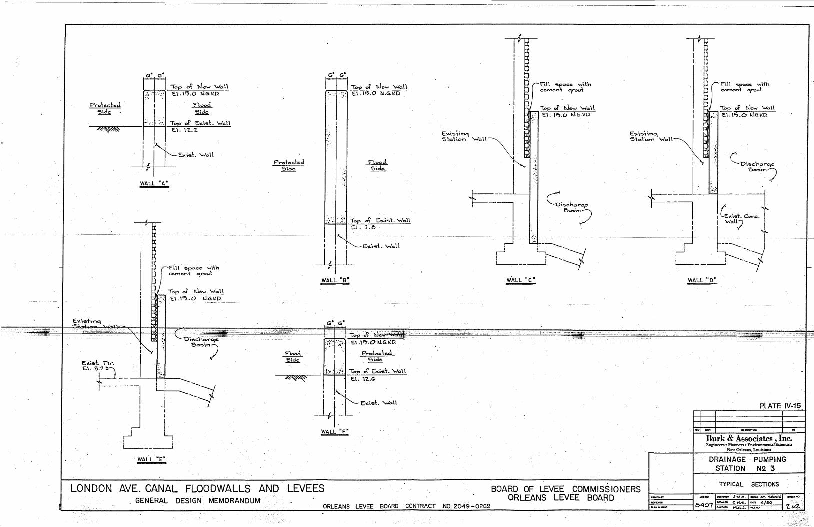
-
'--~_-."':"::-O_'
F'roteded s,de
~~
" <;;" ~
,:; :,::1: ..... :~ ....
"Top of New \"/0.\\ E.\ .1".0 N.G. Y.v.
Flood. Side
'·;,:1' '::;,1 Top of' E")Li.~-\:. \"/011 E\. \"2.:2.
: ;~: #E~;" 'Wall
WALL "A"
.. "-".~."~-... " ...... ., ... n' I I
I ~
~ ,J
Fi\ \ '''!!>po= .... \\h ce ..... eni; 9roLl+
Top or New 'Wan <~] E\.l'?Q /J.G.\l.D.
E:"-\'!!o-\;n~ SJ._~:__ '.1_"_
~ L
. " .1-,
'" ['H ~~ ~ "
.,
, E")Li~t n ....
E\E_~~ ... ~. -.':
I I I
} L I , I I
L..:.---------'
WALL' "E"
T'.·.~ .. .c.~ • '--'Oi~ch~~9~"'~":'~
ea.~i/
----:; ----r
Protected '5'd.e.
c," <;;d ---+--, I I Top at New 'Wo \\ f:.. ,<:',-.:) E.\. 1-:;.0 tJ.G.V.D
:{,: .. '
\-"
rlood '5i.de
';."r}~1 TOE di "'~;.,. walt E.\.7.0·
'/'J...._ ..... . -4L"'~;.1. 'Wall
WALL "B"
G" <;;"
Tr D. .. rnn ~f'ace ,,",i-\'h
ce ..... en-\ 9rou-\:
~ E .... i.~li.n9 ~ S'a';"n 'Wall \ . ~
~I: •. :".';
. Top ~ New 'Wa \ \ El. '~.(j tJ.G .. Y.O
'~'.'
~--~ . I
C:i'5Cho.rge . ea.",? I
j .. 8+--___ _ ,J ~-_---J ~ ---l
WALL "e"
.. --::.:-;";:~~~~---. -:..:.-.:' ~"~--=::.:.:.::_,::: ... ::::;::~:..~~ .... .;.~::~. '.. '0,. : :~. _ ..,;;;:.;.~--;;~::;:;;;:;,-;:;;:.~",:":;:' _ '--
:.~!·.::"I···\:~.:· ~ ..
E.l .\'7.0 tJ.6.V.tc
?roteded 'Side
F"lood Sid.e
~~ .1~:;·,:',,::A:l ~~ ~-\. 'WaH
I I,: I I "'--4l"'''''\. ~\1
WALL "F"
IT i 8 . 0 ~
~ r' Fill ~pa.ee ""Hh ) cement 9'-0\.1\ ., pi ., r' I . Top at New \Na. \\
~:}:I E.\, 1l?0 /J,G.V.D.
E")Li.'5~\n9 'Wa\\~ Sto.hon \
~~ ,
.~ .~., r
\..... D\~cna.rge eC1~i.n)
~ -.;
. ,. 6:::1 J--- -}.. f- '::'::1 I C:~;.,. eo..,.
I : Walt;7 'i-
-;;.- :':;::t~ ~~.::::~~:::.. -;:::"";-;~ ... :......
1 I
... ~ ... ~ I L--__ t~-I
----'
WALL "0"
- - _~o.. :;;;~ ••
-
PLATE IV-15
..,. .. """"'''" ... Burk & Associates, Inc. E.ng;neen • Planners. Environmental Scientists
New Orleans. Louisiana
DRAINAGE STATION
PUMPING NQ 3
LONDON AVE., CANAL FLOODWALLS AND GENERAL DESIGN MEMORANDUM
LEVEES BOARD OF LEVEE COMMISSIONERS TYPICAL SECTIONS
ORLEANS LEVEE BOARD CONTRACT NO. 2049 -0269 ORLEANS LEVEE BOARD I~n I ~~ ~~
=_5407 '2. .. 2' -,::,; .... -: ..
f-

,-
-~
Iii I
I I
- -- _ .. _.- --
-J
~ G w ~
·STA. 103 *00 !
i 3. «::» Q L.: <: C) ~ ~ ~
£:l,.. 1 ~ EWI8'WAI.L"W NEW 12' WALL."F.' EL.
--I----I-!--37 -----
!T-~ 'r£iC '4> s
G 10 £: <I: 5.,-lrJ .,-Ue> ~
t:t"lj-lOrJ <{ SiP
~ NEW IZ' WALL'D,'!.£L.J3.lJ5
~ --:v-~ I" I<J
~'-I I I
j.... EXISTING &DG. lu I<J AI.o.s.<tw.e. DRAIN-
!.oJ <: 3 GE PUMPING ~.... . ......... ".....STATJON""4,;'.,,~·z. ~.~).;.~o_-- .• C-~~·L'-"._'.
"~ -! ! ~ ~rr£Jl,/ III :<l: ~ ~ . __ .V. S: ~ iI.j
- :: ~l , W .tP~ L _____ -"?
=EXTSIlNU.:Mo;..o~ PIPES . ::[S=-rl Elll-: - -:- -. -.. _ .. - .::::::
--.J II II I
II ~ g <: 0 f... \9 ~ Q: Q:
~I II
r
u -,In- .--i--L
!::::=::
~
---------...:-~- I·
/;
5TA.IOO"OO
I I
I
16
SIT£PLAN
o IG SCALE IN FEET
~Z
~ g <: I:? ~i exl Q:,
~
N
~ -¢-
l.i ~?!I-1
~
._--------
~
LEGEND .,1 ~ _ PHASE n INTERIM PROTECTION
1-1- - -.122Z2Z:ZI~cc.PliI\SE1IrPER!ilANENJ 11°~"'~I~
Q
PLATE IV-16
1""'1 I DE""",""", 1 n Burk & Associates, Inc. Engineers • Planners. Environmental Scienti, ••
_ri ____________ ~--_·------~N~·~~.~O~r~le=.m~:Lo~u~is~i.~n.~----·--__ ~
DRAINAGE PUMPING . STATION NQ 4
SITE PLAN
LONDON AVE. CANAL FLOODWALLS AND LEVEES GENERAL DESIGN MEMORANDUM
BOARD OF LEVEE COMMISSIONERS ORLEANS . LEVEE BOARD. ~ I ~NO .-nNO
::::. 040<' 1 OF 'Z. ORLEANS LEVEE BOARD CONTRACT NO. 2049 -0269
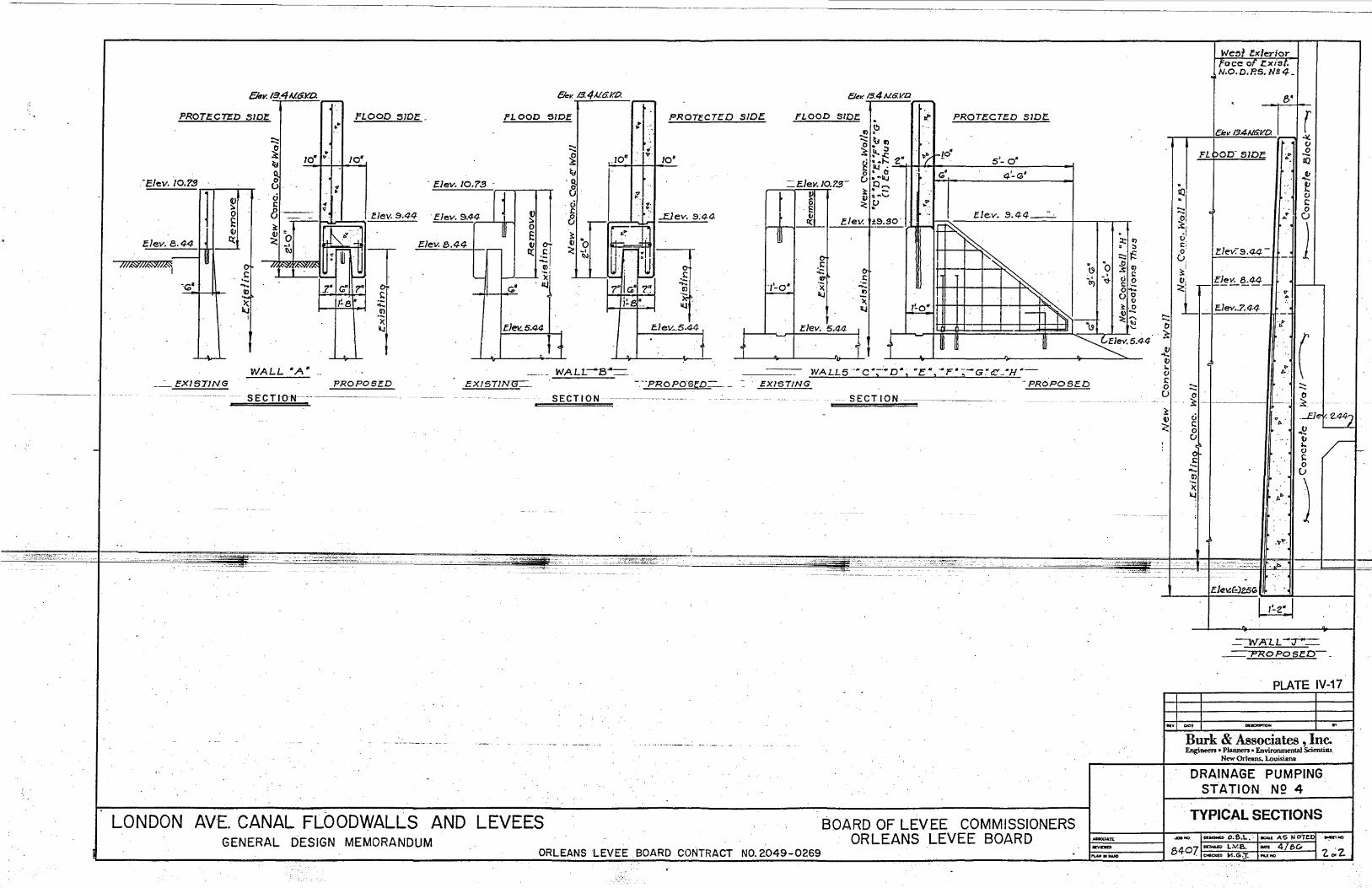
-
CMy.I3.4J.LGy.D. i
l' 10·':'
PROTECTED SIDE FLOOD SIDE_
:::: ~ ~
10'
8 o I: 81-=-~~
.-Elev.l0.'1S
11 ~ 0 E
t
Elev. 9.44
Q)
Ckv.I3.4A/.6.y.o. i
FLOOD SIDE
. EJev. 10.'13
. Elev. 9.1-4 ~ o E
.... ~ ~
'0. (} 0. s::
{3
,!} PROTECTED SIDE
:.I0~ I'I~'I/O'
~. ". ,,:.
EJev. 8.44 I J I Q: Elev. 8.44 ~11f
3:, _ V 0 <:~
/t/W/1M'4
cG'/
W
~ t:1 t '--CO ..... ~
I
1~8
WALL"A- ..
:i::, .~
~
'--
.---
OJ. 1--"---1. :x I
'11.1 (;,'
E.Jev..5.44
11 WALl.--B""-· .
0-~ '-.... OJ .~:
II.!
Elev_5.44 f .
Clev. /3.4uG. v.a i
FLOOD SIDE •
G)~ :::: ~ G)
~I PROTECTED SIDE.
.• ~I' ~"" -. . 5'- O'
=E.Jev; 10.ZS-
~;.z /I ~'o' l;:~ 'I \ ~<;;', 4'-<;;' .,
Q ..... ~. -
JP I -,'-0' ~
0-, s:: :.: U1 .~
IlJ
Q) *'~'-=<:,p .. "':.
Elev. 9.44 __ -_· Elev. W~.SO·
r-"
WALL5-~C';-:"D"; ·E .. ,· .. F·; ..... G.·cf: "H"-'-
"-.... 0 :s Q) .... ~I 0
We~t lx/erioT face of /:.xist.
IN.o.D.P'5.N~4-
, 8'
&.,.~TII CI
FLOOD- S/DE 11 .... 11 ~ ..!!.
• I
"'1 f! 10' ..
:1 CI ~
..... 1 0 .. CJ ~!
A
.1 1 O. E:i
EJev-:s.4,4 -0 v i
~ •. 1,/0" 8.441 f :<:i r ---- 11----'--
i . E.lev • .7 •. 4,4 .. ~ t!
. Ii
I c ZII( s:: .... 0 ..... --EX/STING '-PROPOSED EXI5T1N~ -.--PROPO-SED-EXISTING PRO PO SI:.D
SEC T ION---------·--· SECTION ------------... -.
LONDON AVE. CANAL FLOODWALLS AND LEVEES GENERAL DESIGN MEMORANDUM
ORLEANS LEVEE BOARD CONTRACT NO.2049-0269
-- SECTION
BOARD OF LEVEE COMMISSIONERS ORLEANS LEVEE BOARD
..... U 0
:s: 3: cj v c ~ 0
CJ
0 s:: '-.... a> '-l( ~
0
~jl~~F~'1 .. ..... .. " tJ
I... 0 s: 0
'. Ii ()
'".11 )
." ....
~ _ft.
=-Wl'lLL-~
'"PROPOSED
r ....
....
PLATE IV-17
REw I DUE -. Burk & Associates , In~ Engineers • Plaimen • Environmental Scientists
New Orl~ans. Louisiana
DRAINAGE PUMPING STATION: N2 4
. TYPICAL SECTIONS
I.....,.... ...,...,. ......., ;::::.....,8407 1.'.,;1.

APPENDIX A
PLAN-PROFILE PLATES
General
This appendix contains 13 plan and profile drawings (plates) showing the type, elevation and location of the existing and proposed flood protection structures. Plates A-I through A-7 cover the west side and Plates A-8 through A-13 cover east side of the canal.
Burk and Associates, Inc. 8407 Page A-l

: . : : .•• "!"' ••.•••• --r ...
r-·····r···--r····· --' __ L-I-f-'-.
----11··l :...~.. . :+--~.-; ..... t --; ... t····· 1 .. -....
}' , ....... ; .. I·· .; I ..! ··t:~:: .. +:~.:t~ .. : r:r=~;t-:~ ... :· .. :-~J:~=·~l-·:::·t
0"00 1+00 ·2+00 3+00 4+00
LONDON AVENUE CANAL FLOODWALLS AND LEVEES GENERAL DESIGN MEMORANDUM
5+00 6+00 7+00
ORLEANS LEVEE BOARD CONTRACT NO. 2049-029
15
t+frI+iTt '~+t--IIO ··_·······r········t--··_·l
8+00 9+00 10+00 ""'00 12+00 WESTSIDE
BOARD OF COMMISSIONERS ORLEANS LEVEE BOARD
JOB NO.
8407 PlATE NO.
A-1
Burk & Associates, Inc. Engineers. Planners. Environrnenlal Scienlists
New Orleans. Louisiana
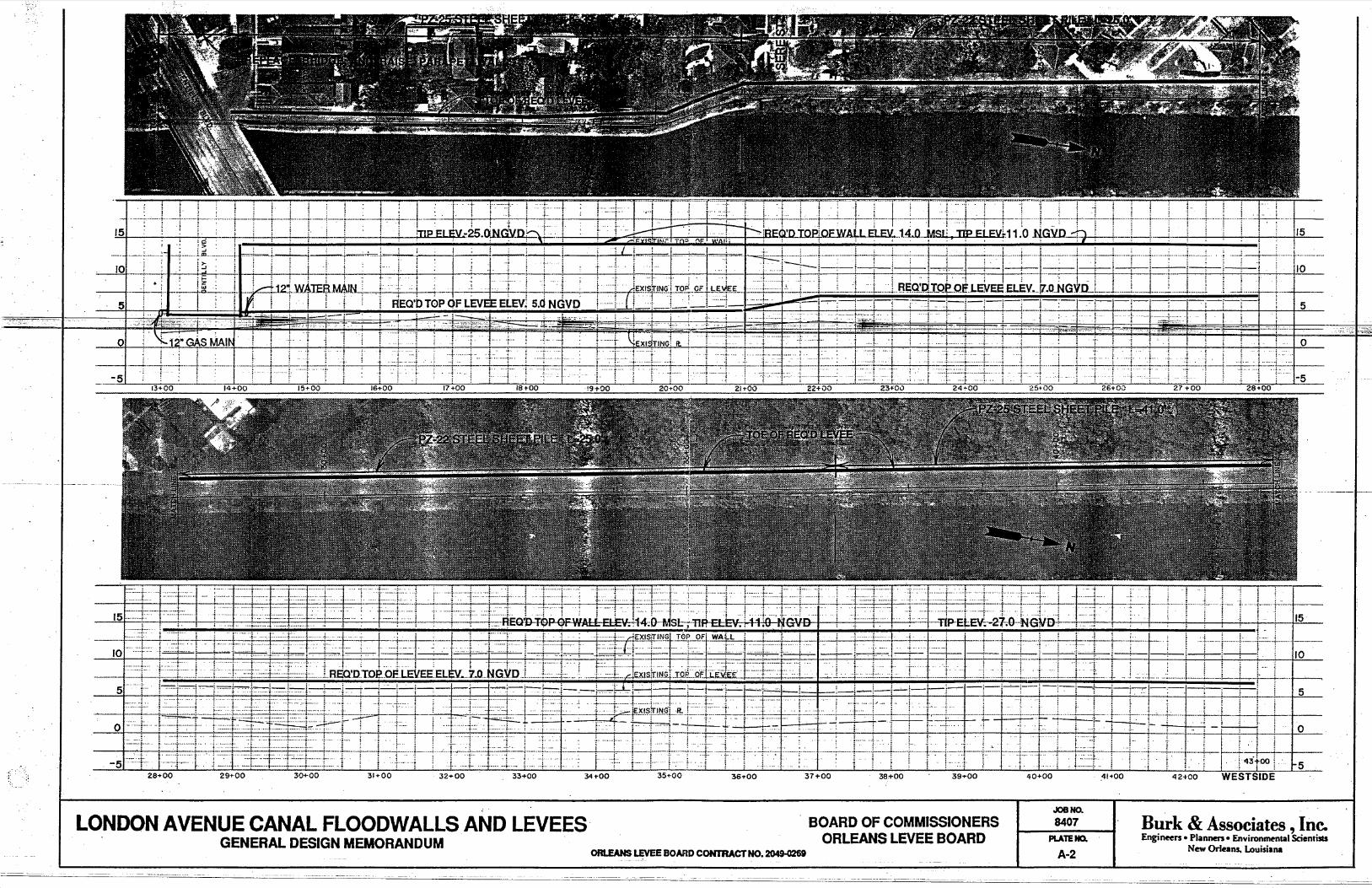
---.- .... -."...--,---;--::-.--
151 .. ;;., . __ --; ; ; , :. : _+_ "mpELI~V~25.0,N.GYnt::::\! ...... : ;' .~_ ,; ,)~.:. r---,.:RECf·DTQP:QEW~L.~ . .t4~Q .. ~SI~,11pE~EVr11.0J{GVO : .. ,: '.' ._+ ... _ .... _ : ,
; '""'''""'-~f-l i -t-~~--I~~--tjlj~i~~ff,+=;]~-~J+---f,:-t7-l:1-1-++
t~-r-J-t:ttt:-rTJ=r~l -Fr.l~;1~;~E-.c rrTl:1ht~rTl. ~IIFfj=~iH~+=++-Jt:t++-H--t t ,. ! , .. ! -' .. · .. ·4· .... ,..+, . . I t- i : ; : ;. ~EQ'D-T-oP OF .iALL EL£\r. : 1-4;P· .. JSf:-;·-nR-EI:EV;1-1-ttO-tjlGVO :.;;.!. =f1P.·E,£V;-27-;O·"-N·GVD-t·· . ..
5 . ~ .. ::··'···F' ...... -1" .... .... :-
..t. ......... :~.::. ··t·
or·:T ... "f .. . .;.... ·i
r.~-.. ·· .1. -·-~··-1· ;····· .. ···t-···" . ··t ! ···t· ····i
1 .. _O:.i.· -5
28+00 29"'00 30+00 31+00 32+00
........ ..:. ... . -i-1
33+00
... ~.: :.::.: .
:.1. ... ;
.! ..
34+00 35+00
. ~ ..
..~ i
36+00
..... --...lJI'--__ -_ ";"'f.·-~·:·,···.r_++ j l~:l::t-~j:F ~ 1: ! I ,
+ :
-"---i:-:~+~ + 37+00 38.+00 39 ... 00 40+00 .41~00 42 .. 00 WESTSIDE
15
LONDON AVENUE CANAL FLOODWALLS AND LEVEES GENERAL DESIGN MEMORANDUM
BOARD OF COMMISSIONERS ORLEANS LEVEE BOARD
JOB NO.
8407 Burk & Associates, Inc. Engineers • Planners. Environm~ntal Scienti!tS
New OrI~ans. Louisiana PLATE NO.
ORLEANS LEVEE BOARD CONTRACT NO. ~ A·2
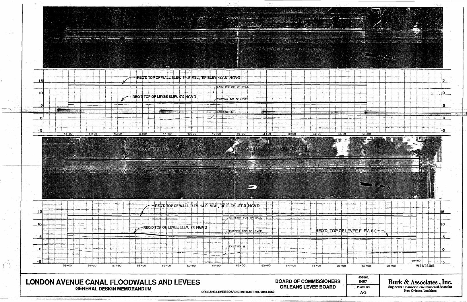
" ,.
~! !
. f-"J':] ···· .. 1_·· .,
5 1-.. .-t:==-.::--- . ';'f
. - -..::...:...' I':';;;:;:~':;:;'';'~~~;~-::~~~:: -).--~. ·:L . ······_···f .. :····-r·······_·1····_·--1 .. -·--··:-···· .. -·-~r'··
01 i' t---+-+
·-i.··=:! c::~-J ... :. ... J .. _ .. ;.--.~-.--... ·:4-~+-··-l-·-~--
5
55+00 56+00 57 .. 00 59+00 60+00
LONDON AVENUE CANAL FLOODWALLS AND LEVEES GENERAL DESIGN MEMORANDUM
.1 . i '
···r--·-···t·-~ , I
! 15
/0
l~r:-:-I""":::']-rl-I-:r i~; jii=.l~l~-t-,",l~ 111 Is :; ·~'::::-·"'f.-~~- -, ~.
,··l----l
61 .. 00 62+00 63+00
ORLEANS LEVEE BOARD CONTRACT NO. 2049-0269
~.- -t I' .. j !
'r 'T, !,. o . ~ .'-' ··1
···1 L l'i==H-i--bf-+ i--::l-t~b+-++:t---i .. ~
64+00 65"'00 66+00
BOARD OF COMMISSIONERS ORLEANS LEVEE BOARD
67"'00
JOB NO.
8407 PLATE NO.
A-3
~:
68+00 WESTSIDE
Burk & AssOciates, Inc. Engineers • Planners. Environm~ntal Scientists
New Orleans. Louisiana .
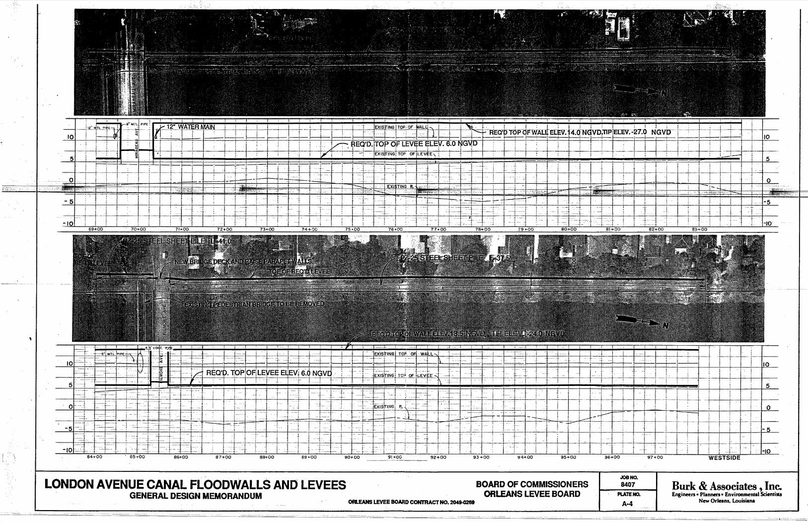
,
10
- - -___ :-=-=1;;::'::::;!,:~
i ··i
LONDON AVENUE CANAL FLOODWALLS AND LEVEES· GENERAL DESIGN MEMORANDUM
1-l
. ______________ 92+00
ORLEANS LEVEE BONiD CONTRACT NO. 204g..()26f
BOARD OF COMMISSIONERS ORlEANS LEVEE BOARD
... ~ ...
+00
JOB NO.
8407 PLATE NO.
A-4
10
~-~~"""""'--'
····-5
Burk & Associates, Inc. Engineers. Planners • Environmental Scientists
New Orleans. Louisiana

:..
5
o
10 .I---+--+-,Fm~~:7-l:::L~.::}.. :r: ···.···r::::·J·
-.
5
~ ~t +-I]~:.f'lrFJl't~F, i.I.i.: +-+~t,! r:~~rlffFb
113+ 00 114 "'00 115+00 116+00 111 + 00 118+00
LONDON AVENUE CANAL FLOODWALLS AND LEVEES GENERAL DESIGN MEMORANDUM
i=ibr .
119+00
' .. ·'·t,·
I' 120+ 00 121+00
ORLEANS LEVEE BOARD CONTRACT NO. 2049-026t
5
o
"" '~~~F~~~t~fDtl j'j~+J-t"::: l· . :-.-... -l ..... -.. ~.
! --W--t--... r- .l .. _ .
5
.~ 1 iT'I~: I-Tll~fl$fH+t~t.t~:-: It2+00 123+00 124 +00
BOARD OF COMMISSIONERS ORLEANS LEVEE BOARD
125+00
JOB NO.
8407 PLATE NO.
A-5
126+00 WESTSIDE
Burk & Associates, Inc. Engineen • Planners • &vironm~ntal Scientists
New OrIel .. Louisiana

LONDON AVENUE CANAL FLOODWALLS AND LEVEES GENERAL DESIGN MEMORANDUM
I ~':':':-,-!-+-' .... - .. +--: - .. ;-.-.-.+-+--~: -+- ,-++-+--'+ +---HI-i -~---'--+- ,-_. - •.. _-_ ... _ ........ .
!46"00 147+00 148+00
BOARD OF COMMISSIONERS ORLEANS LEVEE BOARD
ORLEANS LEVEE BOARD CONTRACT NO. 2049-0269
JOaNO.
8407
PLATE NO.
A-6
. ..L~I~l ~ ._-........ -... I
i .
Burk & Associates, Inc. Engi~n • Plannen. Environm~nlal Scienrists
New Orleans. Louisiana

15 . ····t --L .. __ J._ .. L.. ... -.l._ .. _.-L_.! r-··
-f ·1 .+++-1'1 .. :1 l·IL}:·ll !l.--L-Hi-l! -~'i 't '4' -, 1m; :. I Ilmml til 'it . r m .. '.; . i..: ... . I .
. .,. . >fl······~; i ;, ... ~········t···-:--·-r···-·--: _. j . j_.'
5 ~lll-llfll:±±lli-++-t--t-+I-fft+±J-+H- i +++t+t o
-5 157+00 156+00
LONDON AVENUE CANAL FLOODWALLS AND LEVEES GENERAL DESIGN MEMORANDUM
r-n iTt~=f.rr JI H l-~l ++--H --++r t+H t-J---, ;~; f++ i ~H-H- n+ Tl +: + ,-,
ORLEANS LEVEE BOARD CONTRACT NO. 2049-026i
BOARD OF COMMISSIONERS ORLEANS LEVEE BOARD
JOB NO.
8407 PLATE NO.
A-7
! i; I .. .; ...... -~ .. ~- i j ~l 1"..
WESTSIDE
Burk &·Associates , Inc. Engineers. Planners" Environmental Scienti!lS
New Orleans. Louisiana

_ .. _---t-... _---15
I:::C~~ :i-=~j-~=:_+j~~'D T
. ·--~~~~=f -~~--:·-:F~:- --C--
o ---- ~ ------r-r-
-+-____ -! _______ ~ ___________ L ________ : ___ _
: i t €
-~-'l--l-+ }--I-j
16+ 00
... i····
- ;
! !
-; ~.
-, i .-.... -.~. ·~·~~r~~~;>:T.~;·.~
--}~~q-co..c'i~-i-_J --'I !' -~Hi
-I:~+-H-T--l +~l+ilr
LONDON AVENUE CANAL FLOODWALLS AND LEVEES GENERAL DESIGN MEMORANDUM
ORlEANS LEVEE BOARD CONTRACT NO. ~
23 +00 24~OO
BOARD OF COMMISSIONERS ORLEANS LEVEE BOARD
25+00
JOB NO.
8407 PLATE NO.
A-a
26+00
15
.j l--r-r~~"--!
: i' ---1"--: .... __ ...... -5
o
10
5
o
Burk & Associates, Inc. Engineen. Plannen. Environm~nl.1 Scienrists
New Orleans. Louisiana
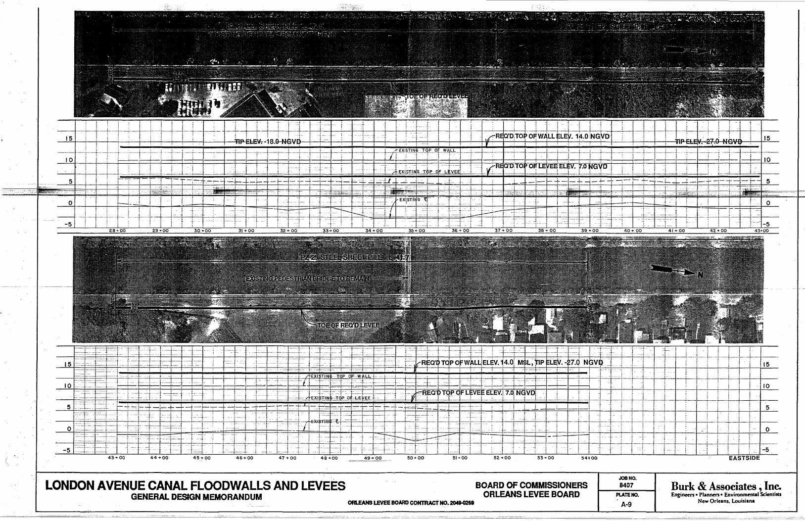
'.
151._ ····-·······l········: ~+--+--_",---+-,···_·····_~·_-·i+-: --···-+I~·~LEV~.i~.ti·~l··-·t-~t~~··I-~-[ '1 'U' ., 15
-;~r=:~tr: ... lm:j:·~··.I.IlifJ±lTII1JII[LJ~~IT] i i •••• ;. ..•••.•..• .1: •••
. I ! :. !---;--!---;--
.... - - ··l·····~··-l······~·~ ............ . !-!- -1-110
.. _.J .-... 1.-1 .. -1._--i~-, L. ..... L .. -.:L .. __ J..:.:. ...
. L~<'~C5~.J . r~~-:J~r;-;- -'i.--"_~ti:-tt.:-+4-++; rr;=ttj::tt[I~: 5 t---'- - L
! .. _ ..•. i.. . ... ~
.1
:-·t-···+ = i~·····+~tI -.. -
-5 43+00 44+00 45+00
.. , .i
46+00
~. ,- ···r !
,j -t···
-r=t:cl-T:i'i'-
47 +00 48+00
LONDON AVENUE CANAL FLOODWALLS AND LEVEES GENERAL DESIGN MEMORANDUM
49+00 50+00 5i+OO -_ ....... _ ............. _.
ORLEANS LEVEE BOARD CONrRACT NO. 204N26t
... .1 f . 'j i ·1 .j . . . . .
.. ~ . ..! .
-:·~.I.~~·r·~t:·;1:·:·:~:t~1···~··+~~;r-::· .
52+00 53+00 54+00
BOARD OF COMMISSIONERS ORUEANS LEVEE BOARD
... f. . . ~
... +. '!"
JOaNO.
8407 PlATEHO.
A·9
. .;. :.t -t·· o
.~·--·1-5
EASTSIDE
Burk & Associates, Inc. Engineers. Planners. Environmental Scientists
New Orleans. Louisiana

...... .,.._--..... __ • .4 ........
.. ~ .. ; ....... -~--.+-........ -.. .
o
15,·::··::::···i- i llt1r-j. J~J~~To~':~;-~=!~J. ltritJ~:E~iPt++-l~t-+-~I=+H---f---i 15
10 i-:l:·~t~-i·· ·Lj2TE~.!·[~'1-=:~[~r±r
5
-5 ··,·····t . f. ... ; .. , ......... .
69+00 70 + 00 71 + 00 72+ 00 73+ 00 74 +00 75+00 76+ 00 77 +00 78+00 79 ... 00 80"'00
LONDON AVENUE CANAL FLOODWALLS AND LEVEES GENERAL DESIGN MEMORANDUM
ORLEANS LEVEE BOARD CONTRACT NO. ~
BOARD OF COMMISSIONERS ORLEANS LEVEE BOARD
81 + 00
JOB NO. 8407 .
PLATE NO.
A-10
82"'00
10
5
o
: 84 +00 L~I-~ 83+00 EASTSIDE
Burk & Associates, Inc. Engineers. Planners. Environmental Scienlists
New Orleans. Louisiana
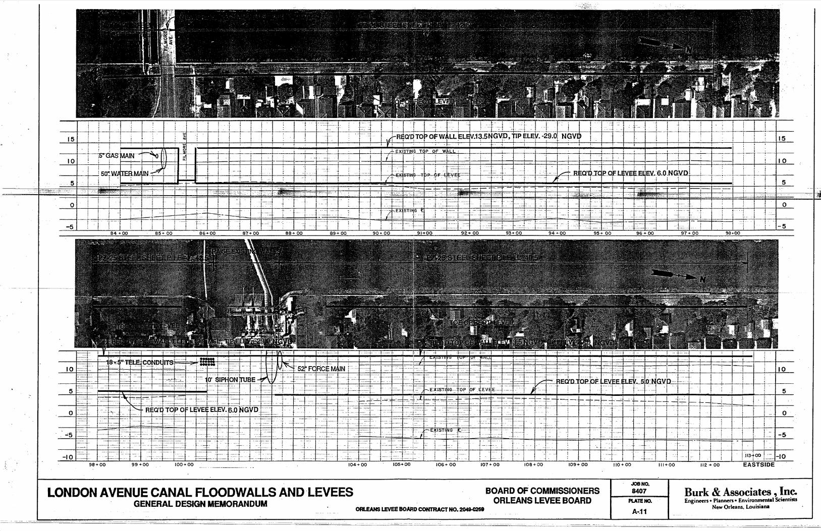
• ;
15 · .... .i····~j··-··r:-~t:···t .. ·-~-·r· '1 ; .. I ,,,. I" ; , ··1·, I , i
····--··· .. ·-T-T· .. --~··t .. ·········l-·· .. -··i·--r-·~-l····-··-~--·-t· .. ··-! ··t·········:·r······-t-·-.. : I·' -1· .. ·~tt:T·g~lrTI1-Il~j--Wrt=1==· ··-r-·-·······+··t···-··~t1·--···T·-t~-t~·-··--··t •• ·-.·····j···-.. · .. ··t .. ·····, ; ······-t ·t········ .......... - ~ ...... j ............ : ...... -... j
'!
--+----t- ·-·i····· ···!······--·t ... i----i- .. -. '·"-"1'·"'·-1--+--':' II 5 ............ + .... _,._ . ..;.. .. _--; ..
101 ····-·t·--;s'GAS~IN~n
10
"lD~t~t j .' ·r··.·!· 5
.LNMm._ . .J.I±J! ·1 ·-=j.~·ll t4-~ _I··:!~··l-~:::J·~ ; ... !=J -~-.J ; : r
5 t ··-:··t . J 5Q~W~. ·····::1· ..
:;;;~~~:~:::-:. '~-" F-,:-:::::F-:,:~:I~··
o 'i ..
.. ,,...;-.. : .... mT .. -5
o
-5-
106+ 00 lOe.;. 00 109+ 00 110+00 111+00
LONDON AVENUE CANAL FLOODWALLS AND LEVEES BOARD OF COMMISSIONERS GENERAL DESIGN MEMORANDUM ORLEANS LEVEE BOARD
JOB NO.
8407 Burk & Associates, Inc. Engineers. Planners. Environmental Scienli!tS
New Orleans. Louisiana PLATE NO.
ORLEANS LEVEE BOARD CONTRACT NO. 2049-0261 A-.11

10
5
o
-5
-10
LONDON AVENUE CANAL FLOODWALLS AND· LEVEES GENERAL DESIGN MEMORANDUM
135+00 136 ... 00 137 +00 138 ... 00
ORLEANS LEVEE BoARD CONTRACT NO. 204l-026I
BOARD OF COMMISSIONERS ORLEANS LEVEE BOARD
139+00 140"'00
JOaNa. .8407
...... 1 --------1 PLATE NO.
A-12
lO
5
o
-5 141+00
Burk & Associates, Inc. Engineers. Planne". Environmrnlal Scienti!lS
New Orleans, Louisiana

15
10
5
o
-5
15
10
o
-5
.~_J ·1 · .. _···r·······t-··_· .. t-·-t .. · ;; .. : I ;-+ . ;' it i ~ ~ BEa'o 'TOP
......... , ... _._.. qF t .. j
.~:~; }'-'1=--.. -~~.---;
"'1 -....• " ~
"1
i ··t··
. -1-1... i
.. · .. ·t·· ... ::1. ····f· i
···-1 .. · .. ······:··· j- ......• ? ..
-.-7i=rj~~:J-l~I~ljr-·-'4:~~8-j----I- ' -r i· .
r .... j.~. ····T··· . "2'"
~~.' ';" ,-._.r= .-~ ·t~·~~~·::::"~·~··--·+··--4-"1 , ........•
. ~ f .
-~_Jj~-LLI 'I-
........ . .. ! ......... "!
. ·····f . .... ~ ....... ::l- .. .
';- .
~ .
.r' .... ~
-, ''f" -+~~'.'!'-'-.l-.'~-1.~, .. -.. :.J:.:: .. +~. l ... -... -.L:-l. ........... l._ .... ~ .-.-... ~ ... -... -
! -:; REQ'Dl TOP iOF LEVEE ELEV.13.Q ! ! ~ . i t iii ; i ~ 15
+._ .. --j- ·l! --"f~~~-'
--:--l-t"=rl~-l---il: +--r ·r: ; ·I! It I 5 i··};"
. .• . =' ~f#, ... -,'.. 7"'": .~ •. - ..•. -.'!-"--"':~~.-- . - ..
I
-lA +ll:: i ) +-h-l- , , -5
1 15
l-r,;~t- S~-F· )1-;t-;i:L:tl-f F~:~: ----i--. ·t .... j
10
,. . · .. ·~··.-r·· .. · .. ~ .... :l. 'r
'.1 ..... :.J .. :. ··:::::·f·:'-· .... _ ••••• .J- .• ;. ..~ ..
........ :-...... i
.. _-- ... :!-_._--_ .. +
151'" 00 152 "'00
··:··:·1~ . ..f··········t····
153"'00
t·· -i
154 + 00
5
" ... I 0
~H~I=-I~I i~-I-, '-~!-1:~~:r=I~~lJ J,-.rf-Hr -+--=FYT-l - ++ i ·1-=-+4+1: -5 154 ... 00 155 .... 00 156+ 00 157+00 158 +·00 159'" 00 EASTSIDE
LONDON AVENUE CANAL FLOODWALLS AND lEVEES BOARD OF COMMISSIONERS ORLEANS LEVEE BOARD
JOB NO.
8407 Burk & Associates, Inc. . .
GENERAL DESIGN MEMORANDUM 0Rl.EAHS lEVEE !BOARD COH'MACT 00. 2049-0269-
PLATE NO.
A-13
Engineers. PlanrH!fS· Environmrnlal Scientists New Orleans. Louisiana