LON Pressure + Temperature Catalogue/Fema...LON Pressure and Differential Pressure Transmitter ......
38
LON Pressure + Temperature H
Transcript of LON Pressure + Temperature Catalogue/Fema...LON Pressure and Differential Pressure Transmitter ......

LON Pressure + Temperature
H
01331_Product Catalog_02 19.02.2002 9:27 Uhr Seite 39

40
H
0… + 250 25000 SKN 250-L0… + 1250 40000 SKN 1250-L
–250… + 250 25000 SKVN 250-L–1250… + 1250 40000 SKVN 1250-L
LON Pressure and Differential Pressure Transmitter
Moduflex · Type series LON
Product Description and ApplicationsPressure- and Differential Pressure Transmitter for Filter Monitoring and Ventilation control accordingstandard of LONMARK®.The Transmitter is able to handle Overpressure (Pressure connector + ), Vacuum (Pressure connector –)and Differential Pressure (High Pressure on connector + and Low Pressure on connector –).
Technical dataCable entry Plug connection M 12 four-pole
(a four- or five-pole plug may be used)Operating voltage 24 VAC ± 20 % or 24 V...36 VDCProtection class IP 65 Transceiver and profile FTT 10 A (LPT 10 compatible)
LONMARK® certificated Profil 1030Compensated temperature range 0…50 °CMax. medium temperature –25…+85 °C,
max. 95 % relative humidityMaterials Electronic housing: MacrolonAccessories included in delivery – Plug M 12 five-pole
– 2 m of silicone hose– 2 joining pipes with extensions– Mounting bracket H 11
Serviceability■ Service LED visible
from outside■ Operation LED visible
from outside■ Trigger Switch for
Neuron ID accessibleafter removing Lid
■ Barcode with Neuron IDoutside placed
■ Connection via 5-poleM12 Plug, A-coded
H 11joining pipe
DPS-J
Technical data transmitterPressure port 5 mm hose unionInstallation With mounting bracket H 11 direct on the wallLinearity ≤ 1 % FSMeasuring method piezoresistive
Type seriesSKN…L, SKVN…-L
Working range Max. allowable Type(nominal range) pressure
(Pa) (Pa)
Lon-Accessory Plug M 12 five-pole ST 3555-pole T-divider TST 355
XIF-file Low Pressure (≤ 32.76 kPa) XIFLP 1High Pressure (≥ 32.77 kPa) XIFHP 1
Plug-In and XIF-files by E-Mail: [email protected]
TST
01331_Product Catalog_02 19.02.2002 9:27 Uhr Seite 40
41
H
Working range Working range Max. allowable Type(nominal range) (nominal range) pressure
(kPa) (bar) (kPa)
LON Pressure and Differential Pressure Transmitter for liquid and gaseous media
Moduflex · Type series LON
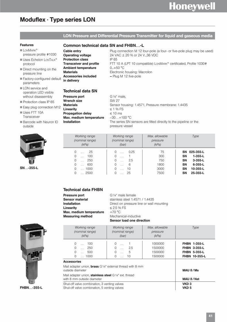
Common technical data SN and FHBN…-LCable entry Plug connection M 12 four-pole (a four- or five-pole plug may be used)Operating voltage 24 VAC ± 20 % or 24 V...36 VDCProtection class IP 65Transceiver and profile FTT 10 A (LPT 10 compatible) LONMARK® certificated, Profile 1030#Ambient temperature 0...+50 °CMaterials Electronic housing: MacrolonAccessories included – Plug M 12 five-polein delivery
Technical data SNPressure port G|� male, Wrench size SW 27Materials Sensor housing: 1.4571, Pressure membrane: 1.4435Linearity ≤ 1 % FSPropagation delay ≤ 10 msMax. medium temperature –30…+100 °CInstallation The series SN sensors are fitted directly to the pipeline or the
pressure vessel
Features■ LONMARK®
pressure profile #1030
■ Uses Echelon LONTALK®
protocol
■ Direct mounting on thepressure line
■ Factory-configured defaultparameters
■ LON service and operation LED visible without disassembly
■ Protection class IP 65
■ Easy plug connection M12
■ Uses FTT 10A Transceiver
■ Barcode with Neuron IDoutside
0 … 25 0 … 0.25 75 SN 025-355-L0 … 100 0 … 1 300 SN 1-355-L0 … 250 0 … 2.5 750 SN 3-355-L0 … 600 0 … 6 1800 SN 6-355-L0 … 1000 0 … 10 3000 SN 10-355-L0 … 2500 0 … 25 7500 SN 25-355-L
Technical data FHBNPressure port G[� male femaleSensor material stainless steel 1.4571 / 1.4435Installation Direct on pressure line or wall mountingLinearity ≤ 2.5 % FSMax. medium temperature +70 °CMeasuring method Mechanical-inductive
Sensor load one direction
0 … 100 0 … 1 1000000 FHBN 1-355-L0 … 250 0 … 2.5 1500000 FHBN 3-355-L0 … 500 0 … 5 1500000 FHBN 5-355-L0 … 1000 0 … 10 1500000 FHBN 10-355-L
Accessories
Mail adapter union, brass G[� external thread with 8 mm outside diameter MAU 8 / Ms
Mail adapter union, stainless steel G[� ext. thread with 8 mm outside diameter MAU 8 / Nst
Shut-off valve combination, 3 venting valves VKD 3Shut-off valve combination, 5 venting valves VKD 5
SN…-355-L
FHBN…-355-L
Working range Working range Max. allowable Type(nominal range) (nominal range) pressure
(kPa) (bar) (kPa)
01331_Product Catalog_02 19.02.2002 9:27 Uhr Seite 41
42
H
LON Temperature Sensors
Moduflex · Type series LON
Application■ Temperature Transmitter for heating, district heating, air conditioning and ventilation according
standards of LONMARK®.
■ Fast medium temperature recording in district heating systems, solar circuits and cooling systems(T7425…).
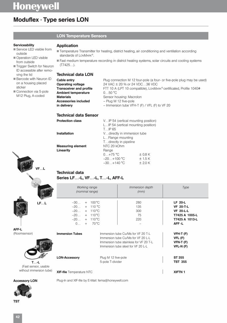
Technical data LONCable entry Plug connection M 12 four-pole (a four- or five-pole plug may be used)Operating voltage 24 VAC ± 20 % or 24 VDC…36 VDCTransceiver and profile FTT 10 A (LPT 10 compatible), LONMARK® certificated, Profile 1040#Ambient temperature 0…50 °CMaterials Sensor housing: MacrolonAccessories included – Plug M 12 five-polein delivery – Immersion tube VFH-T (F) / VFL (F) to VF 20
Technical data SensorProtection class V…IP 54 (vertical mounting position)
L…IP 54 (vertical mounting position)T…IP 65
Installation V…directly in immersion tubeL…Flange mountingT…directly in pipeline
Measuring element NTC 20 kOhmLinearity Range
0…+75 °C ± 0.8 K–20…+100 °C ± 1.5 K–30…+140 °C ± 2.0 K
Technical data Series LF…-L, VF…-L, T…-L, AFF-L
Accessory LON
Working range Immersion depth Type(nominal range) (mm)
–30… + 100 °C 280 LF 20-L–20… + 110 °C 135 VF 20-T-L–20… + 110 °C 300 VF 20-L-L–20… + 110 °C 75 T7425 A 1005-L–20… + 110 °C 220 T7425 A 1013-L
0… + 70 °C – AFF -L
Immersion Tubes Immersion tube Cu/Ms for VF 20 T-L VFH-T (F)Immersion tube Cu/Ms for VF 20 L-L VFL (F)Immersion tube stainless for VF 20 T-L VFN-T (F)Immersion tube steel for VF 20 L-L VFL-N (F)
LON-Accessory Plug M 12 five-pole ST 3555-pole T-divider TST 355
XIF-file Temperature NTC XIFTN 1
Plug-In and XIF-file by E-Mail: [email protected]
TST
LF…L
AFF-L(Roomsensor)
T…-L(Fast sensor, usable
without immersion tube)
Serviceability■ Service LED visible from
outside■ Operation LED visible
from outside■ Trigger Switch for Neuron
ID accessible after remo-ving the lid
■ Barcode with Neuron IDon a housing placedsticker
■ Connection via 5-poleM12 Plug, A-coded
VF…L
01331_Product Catalog_02 19.02.2002 9:27 Uhr Seite 42

Temperature Sensors
H
01331_Product Catalog_02 19.02.2002 9:27 Uhr Seite 43

44
H
Two-phase frost protection
Type series FTS
Analog frost protectionWith falling temperature the frost protection generates a rising output signal 0–10 V.
Switching functionIf the temperature drops further, a limiter contact (single-pole changeover contact) is actuated.
Maximum selection for valve signalIf the output signal of the controller (Y signal) is looped through the frost protection, a maximum selection of the two signals takes place. If the Y signal from the controller is larger than the output signal of the frost protection, the controller determines the position of the heating valve (normal operation). If the output signal of the frost protection is larger than the Y signal of the controller (risk of frost), then the frost protection determines the position of the heating valve.
Self-monitoring sensorThe sensor acting over the entire length is self-monitoring, i. e. in the case of breakage or dama-ge of the capillary tube, “Risk of frost” is signaled. If the signal of the controller is not looped through, then the FTS outputs the frost control signal.
Cascades for large coilsFor very large heating coils several FTS can be used in cascade.
FTS
Technical dataSupply voltage 24 VAC ± 20 % or 24–36 VDCOutput signal 0–10 V + floating limiter contact (at falling temperature)Power consumption max. 1 WCable entry 2 x Pg 11 for electronic Large user friendly plug connection to
DIN 43650 for limit value switch.Degree of protection IP 65Installation With 2 size 4 mm screws directly one the duct wall.
5 capillary tube holders, Type H3 are included in the supply.Ambient temperature 12–50 °C
Caution: at ambient temperatures below 10 °C, the unit reacts andsignals “Risk of frost”.
Switching capacity 8 A 250 VAC
Range of action Capillary tube Type
10…3 °C 6 m FTS 01510…3 °C 3 m FTSB 015
Packaging includes 5 capillary tube holders Type H 3.
Characteristics
Terminal connection
1st phaseA = 10 °C Start of the working point (with falling temperature)
B = 5 °CEnd of the constant range
2nd phaseC = 4 °CSwitching back point of the limitercontact
D = 3 °CSwitching point of the limiter contact
with limiter contact and integrated priority selection
Block circuit diagramController
Connection diagramsPlug connection
01331_Product Catalog_02 19.02.2002 9:27 Uhr Seite 44
45
H
Immersion depth L Type(mm)
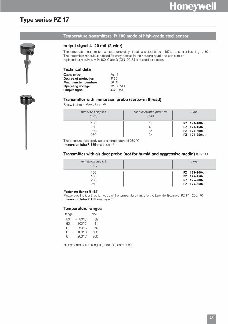
Temperature transmitters, Pt 100 made of high-grade steel sensor
Type series PZ 17
The temperature transmitters consist completely of stainless steel (tube 1.4571, transmitter housing 1.4301).The transmitter module is housed for easy access in the housing head and can also be replaced as required. A Pt 100, Class B (DIN IEC 751) is used as sensor.
Technical dataCable entry Pg 11Degree of protection IP 65Maximum temperature 60 °COperating voltage 12–36 VDCOutput signal 4–20 mA
Temperature rangesRange No.
–50 … + 50 °C 55–50 … + 100 °C 510 … 50 °C 500 … 100 °C 1000 … 200 °C 200
Higher temperature ranges (to 600 °C) on request.
Transmitter with immersion probe (screw-in thread)Screw in thread G|�, 8 mm Ø
100 PZ 177-100/…150 PZ 177-150/…200 PZ 177-200/…250 PZ 177-250/…
Fastening flange R 187.Please add the identification code of the temperature range to the type No. Example: PZ 171-200/100Immersion tube R 185 see page 46.
Transmitter with air duct probe (not for humid and aggressive media) 8 mm Ø
output signal 4–20 mA (2-wire)
Immersion depth L Max. allowable pressure Type(mm) (bar)
100 40 PZ 171-100/…150 40 PZ 171-150/…200 35 PZ 171-200/…250 34 PZ 171-250/…
The pressure data apply up to a temperature of 250 °C.Immersion tube R 185 see page 46.
01331_Product Catalog_02 19.02.2002 9:28 Uhr Seite 45

46
HType series P 17
Immersion tube G ||� (only for P 171…, P 271… and PZ 171…)
Immersion depth Max. pressure Type Type(mm) (bar) Pt 1000 Pt 100
100 40 P 277-100 P 177-100150 40 P 277-150 P 177-150200 35 P 277-200 P 177-200250 35 P 277-250 P 177-250
Mounting flange R 187.
Air duct probe (not for humid and aggressive media) 8 mm Ø
Immersion depth (L) (mm) Type
100 R 185-100150 R 185-150200 R 185-200250 R 185-250
Mounting flange R 187for air duct probe, stainless steel 1.4571
R 187
R 18 R 185
Temperature sensors Pt 100 / Pt 1000 in stainless steel
The temperature sensors consist completely of high-grade steel (tube: 1.4571, terminal housing: 1.4301).
Technical dataSensor element Pt…, Class B to DIN IEC 751, 3-wire-connectionCable entry Pg 11Degree of protection IP 65Temperature range –50…600 °C
Immersion depth Max. pressure Type Type(mm) (bar) Pt 1000 Pt 100
100 40 P 271-100 P 171-100150 40 P 271-150 P 171-150200 35 P 271-200 P 171-200250 35 P 271-250 P 171-250
The pressure data apply up to a temperature of 250 °C.Immersion tube R 185.
Immersion probe with screw-in thread G ||� 8 mm Ø
01331_Product Catalog_02 19.02.2002 9:28 Uhr Seite 46

Thermostats + Hygrostats
H
01331_Product Catalog_02 19.02.2002 9:28 Uhr Seite 47
48
H
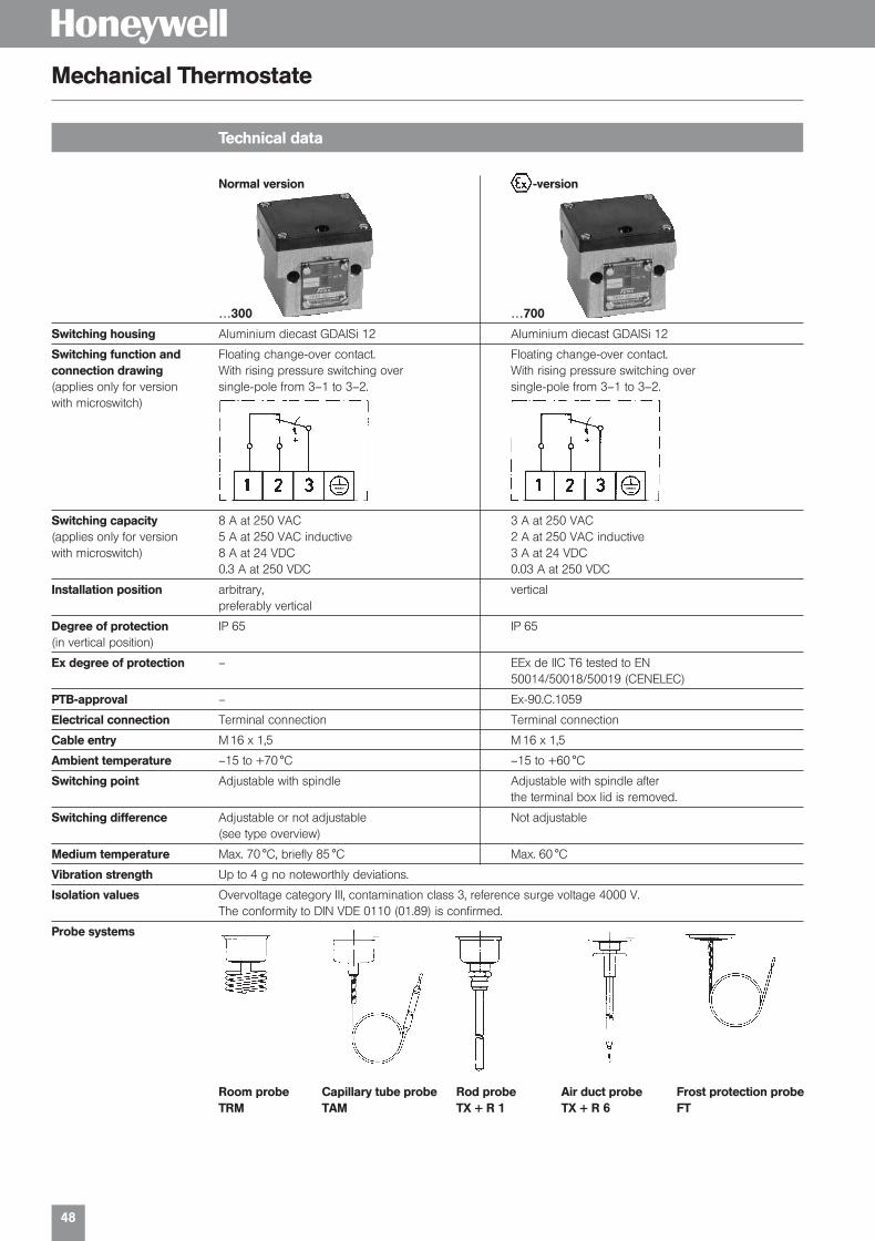
Technical data
Mechanical Thermostate
Normal version -version
…300 …700
Switching housing Aluminium diecast GDAISi 12 Aluminium diecast GDAISi 12
Switching function and Floating change-over contact. Floating change-over contact.connection drawing With rising pressure switching over With rising pressure switching over(applies only for version single-pole from 3–1 to 3–2. single-pole from 3–1 to 3–2.with microswitch)
Switching capacity 8 A at 250 VAC 3 A at 250 VAC(applies only for version 5 A at 250 VAC inductive 2 A at 250 VAC inductivewith microswitch) 8 A at 24 VDC 3 A at 24 VDC
0.3 A at 250 VDC 0.03 A at 250 VDC
Installation position arbitrary, verticalpreferably vertical
Degree of protection IP 65 IP 65(in vertical position)
Ex degree of protection – EEx de IIC T6 tested to EN50014/50018/50019 (CENELEC)
PTB-approval – Ex-90.C.1059
Electrical connection Terminal connection Terminal connection
Cable entry M 16 x 1,5 M 16 x 1,5
Ambient temperature –15 to +70 °C –15 to +60 °C
Switching point Adjustable with spindle Adjustable with spindle afterthe terminal box lid is removed.
Switching difference Adjustable or not adjustable Not adjustable(see type overview)
Medium temperature Max. 70 °C, briefly 85 °C Max. 60 °C
Vibration strength Up to 4 g no noteworthly deviations.
Isolation values Overvoltage category III, contamination class 3, reference surge voltage 4000 V.The conformity to DIN VDE 0110 (01.89) is confirmed.
Probe systems
Room probeTRM
Capillary tube probeTAM
Rod probeTX + R 1
Air duct probeTX + R 6
Frost protection probeFT
01331_Product Catalog_02 19.02.2002 9:28 Uhr Seite 48

49
H
Switch units / connection diagrams
Thermostats
Terminal connection Description Connection diagramsSeries 300
Normal versionmicroswitch, single pole changeover
ZFT 213 Gilded contactswith little transition resistance(e. g. for low tension)Cannot be supplied with adjustable switchingdifferential
ST 218 Plug connector with position indication12 V–240 VAC/DC
ZFT 351 Degree of protection IP 65with surface protectionHousing series 300(Terminal connections)
ZFT 513 EExi-versionhousing 300, cable entry and terminals blueGold plated contacts, degree of protection IP 65
ZFT 5970 Adjustment of one switching point according to customers instruction
ZFT 5971 Adjustment and sealing of switching points according to customers instruction
Example for ordering:TX 150-513
Code for optional function (minimum limiter)Code of temperature rangeType
01331_Product Catalog_02 19.02.2002 9:28 Uhr Seite 49

50
H
Range of adjustment Switching diff. Max. allowable Type(Mean value) temperature on sensor
Range of adjustment Switching diff. Max. permissible Type(Mean value) temperature on sensor
Industrial room thermostats
Type series TRM
Capillary tube thermostats with 1.5 m capillary tube
Type series TAM
Fema room thermostats are suitable for industrial plants, for greenhouses, stables, and warehouses,also for monitoring the maximum temperature in switchgear cabinets and relay stations.Room thermostats are supplied complete with H 1 wall bracket.
Switching differential not adjustable
-20/+20 °C 1.0 K 70 °C TRM 022-3010/+40 °C 1.0 K 70 °C TRM 40-301
+10/+50 °C 1.0 K 70 °C TRM 150-301
Switching differential adjustable
0/+40 °C 3–10 K 70 °C TRM 40-303+10/+50 °C 3–10 K 70 °C TRM 150-303
Switching differential not adjustable
-20/+20 °C 1.0 K 60 °C Ex-TRM 0220/+40 °C 1.0 K 60 °C Ex-TRM 40
+10/+50 °C 1.0 K 60 °C Ex-TRM 150
-version · Degree of protection EEx de IIC T6
The sensor cartridge at the end of the capillary tube is the actual active (temperature-sensitive) part ofthe sensor. Changes in temperature on the capillary tube have no effect on the switching point.Pressure -tight installation of the sensor in pressure vessels of all kinds is possible with the aid of immer-sion tubes.
Immersion tubes R….
Switching differential not adjustable
-20/+20 °C 1.5 K 110 °C TAM 022-301+10/+50 °C 1.5 K 110 °C TAM 150-301+40/+90 °C 2.0 K 125 °C TAM 490-301+80/+130 °C 2.0 K 150 °C TAM 813-301
-20/+20 °C 1.5 K 110 °C Ex-TAM 022+10/+50 °C 1.5 K 110 °C Ex-TAM 150+40/+90 °C 2.0 K 125 °C Ex-TAM 490+80/+130 °C 2.0 K 150 °C Ex-TAM 813
-version · Degree of protection EEx de IIC T6
TRM 40-301
TAM 490-301
Range of adjustment Switching diff. Max. allowable Type(Mean value) temperature on sensor
Range of adjustment Switching diff. Max. allowable Type(Mean value) temperature on sensor
01331_Product Catalog_02 19.02.2002 9:28 Uhr Seite 50

51
H
Rod thermostats (without immersion tube)
Type series TX
Temperature monitors, temperature limiters component tested
Type series STB
Rod thermostats can be installed as immersion thermostats in pipelines and containers and for monitoring temperature in air ducts. The suitable immersion tube has to be chosen according to the application.3650
Range of adjustment Switching diff. Max. allowable Immersion Type(Mean value) temp. on sensor depth (mm)
–20/+30 °C 1.5 K 110 °C 135 TX 023-301+10/+50 °C 1.5 K 110 °C 135 TX 150-301+40/+90 °C 2.5 K 125 °C 135 TX 490-301+80/+130 °C 4.0 K 150 °C 135 TX 813-301–20/+30 °C 1.5 K 110 °C 220 TXB 023-301+10/+50 °C 1.5 K 110 °C 220 TXB 150-301+40/+90 °C 2.5 K 125 °C 220 TXB 490-301+80/+130 °C 4.0 K 150 °C 220 TXB 813-301
Range of adjustment Switching diff. Max. allowable Immersion Type(Mean value) temp. on sensor depth (mm)
–20/+30 °C 1.5 K 110 °C 135 Ex-TX 023+10/+50 °C 1.5 K 110 °C 135 Ex-TX 150+40/+90 °C 2.5 K 125 °C 135 Ex-TX 490–20/+30 °C 1.5 K 110 °C 220 Ex-TXB 023+10/+50 °C 1.5 K 110 °C 220 Ex-TXB 150+40/+90 °C 2.5 K 125 °C 220 Ex-TXB 490
-version · Degree of protection EEx de IIC T6
TX 023-301
Ex-TX 150
The temperature monitors and temperature limiters correspond to the requirements of DIN 3440 andcan thus be used for heating systems according to DIN 4751, for steam and hot water systems and fordistrict heating systems. The devices with safety function (STW, STB) are self-monitoring, i. e. in the caseof breakage or leaks in the measuring system, the circuit is opened and the system is switched off to thesafe side.
Type summary
Setting range Max. temperature Immersion Typeat the probe depth (mm)
20–150 °C 175 °C 150 STW 1 F20–150 °C 175 °C 150 STW + TRF30–110 °C 130 °C 150 STB + TWF30–110 °C 130 °C 150 STB + TRF60–130 °C 150 °C 150 STB 1 F20–150 °C 175 °C 100 TWP 1 F
HousingAluminium diecasting with plastic cover
Immersion tube(included in supply): brassScrew-in thread: G|�
Immersion depth: see typeoverview
Switching capacity10 (2) A, 250 VAC
Type of protection IP 54
Temperature monitor, TÜV-test Immersion Typetemperature limiter certificate depth
STB 1 F STB 89 501 150 mm T 4 NST FTWP 1 F TW 89 201STW 1 F STW (STB) 89 401 SSTB + TW F TW/STB 90 401 150 mm T 5 NST F STB + TR F TR/STB 90 001STW + TR F TR/STW (STB) 89 901 S
Immersion tubes
01331_Product Catalog_02 19.02.2002 9:28 Uhr Seite 51

52
H
Frost protection thermostats
Type series T69
Frost protection thermostats for air heating and conditioning systems
Type series FT
If the temperature falls below the set value over a min. length of 3–5 cm, the thermostat switches off.A fixed stop on the setting spindle at 4 °C prevents the thermostat from being set below the freezingpoint due to in expert adjustment. If the capillary tube is damaged or broken, the Fema frost protection thermostats reliably switch off towards the safe side (e. g. fan off), irrespective of the temperature at thesensor. Capillary tube holders H 3 are included.
Range of adjustment Max. temperature Version Typeon sensor
4–15 °C 200 °C 6 m capillary tube FT 0154–15 °C 200 °C 3 m capillary tube FTB 015
Version with manual reset4–15 °C 200 °C 6 m capillary tube FT 015-2064–15 °C 200 °C 3 m capillary tube FTB 015-206
Plug connection to DIN 43650
4–15 °C 200 °C 6 m capillary tube Ex-FT 0154–15 °C 200 °C 3 m capillary tube Ex-FTB 015
Two-phase frost protection control system with output signal 0–10 V and limit switch.
-version · Degree of protection EEx de IIC T6
■ large service friendly plug
■ easy check of correctconnection by removingthe plug
■ Reheaters in air conditioning systems■ Heat exchanger in cooling systems■ Gas-filled copper sensible element with 1.8 m
bulb length or 3 m and 6 m coil length■ Dust-tight (Honeywell) micro switch the
switching contacts (heat/cool)
■ Protection class I (T6950/51) accordingEN60335-1, IP40 according EN60529
■ Easy installation and wiring■ Manual Reset (T6950/60), Automatic Reset
(T6951A/61A)■ all 1.8 m versions with immersion bulb
The Single Stage Thermostat series T6950A/51A/60A/61A provides the antifreeze function. Designedfor systems where temperature may not drop under a certain fixed safety value such as:
Range of adjustment–10 °C…+12 °C
Max. overload temperature200 °C (max. 60 min.)
Housing materialABS and corrosion protec-ted steel (IP65 Macrolon)
Switching capacity24…250 VAC; 18 (8) A
Hysteresis1 K
Type of protection Length of capillary tube TypeIP m
40 1.8 m T6951A100940 3.0 m T6951A101740 6.0 m T6951A102565 1.8 m T6961A100765 3.0 m T6961A101565 6.0 m T6961A1023
Frost protection thermostats
Type of protection Length of capillary tube TypeIP m
40 1.8 m T6950A100040 3.0 m T6950A101840 6.0 m T6950A102665 1.8 m T6960A100865 3.0 m T6960A101665 6.0 m T6960A1024
Frost Protection Limiter (with internal interlock)
T69
FT015
01331_Product Catalog_02 19.02.2002 9:28 Uhr Seite 52

53
H
TKM 50-315
Strap-on thermostats for underfloor heating
Type series TKM
Self-monitoringFeatures■ Self monitoring sensor■ Solid, robust housing■ Easy installation■ Heat compound and
tension band|� to 2� included
Description The fast responding sensor system is also self-monitoring. If the sensor is broken or damaged, the thermostat behaves as though the temperature had exceeded the set value it switches off towards thesafe side (e.g. circulating pump off). The response sensitivity can be improved by using a heat conducting compound between the pipe and the contact face of the sensor. Heat conducting compound is included with each unit. It is important that the surface of the pipe is carefully cleaned and free from dirt, scale and paint beforefitting the sensor. The tension band included with each thermostat enables the contact thermostats to beattached to pipes of nominal diameters |� to 2�.
Type selection for underfloor heating applicationsThe switching point should be 10 K above the temperature of the underfloor heating systems.
Technical dataCasing Aluminium die-cast GD AI Si 12 according to DIN 1725.
Terminal box lid made of glass fibre reinforced plastic.Mounting position OptionalFitting With tension band directly on the pipe. Suitable for nominal
diameters of pipe from |� to 2�.Max. Ambient temperature 70 °CMax. Temperature at the sensor 100 °CSwitching temperature Adjustable with screwdriver after removal of the terminal box cover.
For ranges see summary of types.Switching differential Not adjustable. For values see summary of types.Contact complement Single-pole changeover. Two-pole version on enquiry.Switching capacity 8 (5) A 250 VACType of protection IP 54 according to DIN 40050 (in case of vertical mounting)Connection 3-pole terminal strip and earth conductor connection. Accessible
after removal of the terminal box cover. Cable entry Pg 11, max.cable diameter 10 mm.
Adjustment The specified setting values relate to the upper switching point(with rising temperature). The lower switching point (with fallingtemperature) is lower by the switching differential.
Range of adjustment Switching differential Factory-set Type(Mean Values) at
45–50 °C 6 K 50 °C TKM 50-31555–60 °C 6 K 60 °C TKM 60-31565–70 °C 6 K 70 °C TKM 70-315
Summary of types
Connection diagram
01331_Product Catalog_02 19.02.2002 9:28 Uhr Seite 53

54
H
Single and Dual Stage Industrial Room Thermostats T6120 A/B
Industrial Room Thermostats
General Application The T6120A and B Single- and Dual-Stage Industrial Room Thermostats are designed for measuring,monitoring, and controlling temperatures in heating and cooling systems. These thermostats are suitablefor the following areas of applications.
■ commercial buildings■ garages■ factories
■ storage rooms■ machine rooms
■ greenhouses and■ agricultural installations
Technical data T6120A1005 T6120B1003
Max. current 10 (1,5) A, 250 VAC 15 (8) A, 24…250 VACMax. bulb temperature +65 °C +60 °CSwitching differential 1 °C 1 °CProtection standard IP 54 IP 65Weight 360 g 530 gDifference between 2 stages – 2…10 KHousing material glass fibre reinforced ABSElectrical connection Screw terminal block for wiring up 1,5 mm2
Wiring and function T6120A1005
HeatingConnect terminal 2 and terminal 3. The contact opens while the temperature is increasing.
CoolingConnect terminal 1 and 2. The contact opens while the temperature is decreasing.
Order No. Stage Housing temperature Temperature range
T6120A1005 single -10…+65 °C 0…+40 °CT6120B1003 dual -15…+60 °C -30…+30 °C
Wiring and function T6120B1003
HeatingConnect Red (common) to blue terminal; the contact opens while rising of the temperature in the following sequence: Stage 2, Stage 1.
CoolingConnect Red (common) to white terminal; the contact opens while dropping of the temperature in the following sequence: Stage 1, Stage 2.
Differential setting
Switching differential between both stages can be adjusted by a inside setpoint lever mounted belowthe mircro switch “stage 2”.Turning the lever to the sensor side means – increase of switching differentialTurning the lever to the cable entry side means – degrease of switching differential
T6120A1005
01331_Product Catalog_02 19.02.2002 9:28 Uhr Seite 54
5555
H
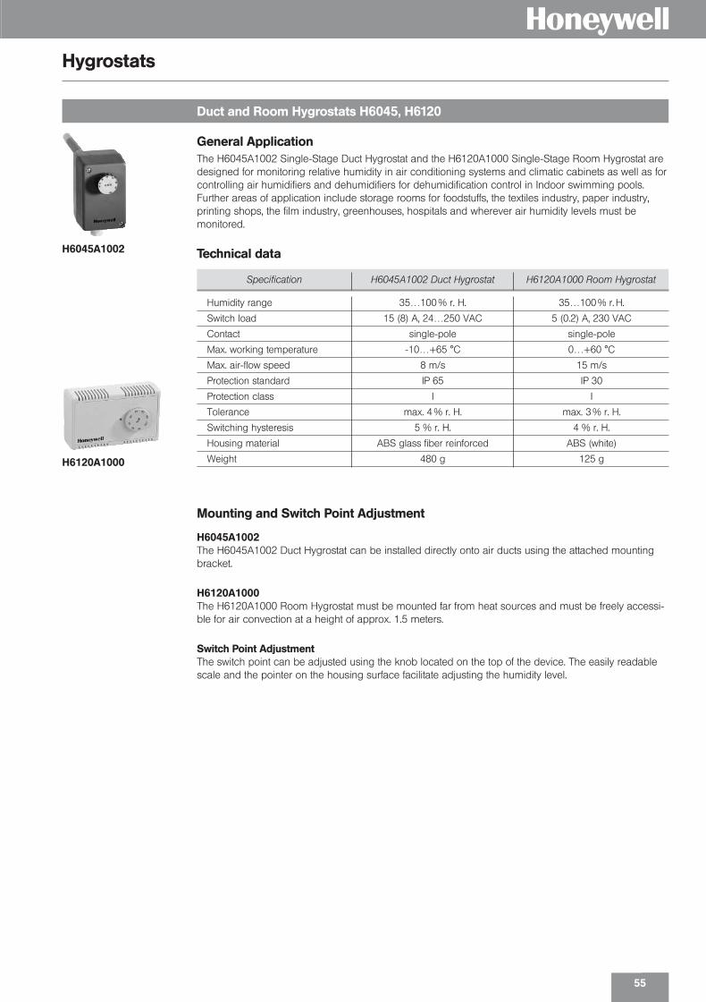
Duct and Room Hygrostats H6045, H6120
Hygrostats
General Application The H6045A1002 Single-Stage Duct Hygrostat and the H6120A1000 Single-Stage Room Hygrostat aredesigned for monitoring relative humidity in air conditioning systems and climatic cabinets as well as forcontrolling air humidifiers and dehumidifiers for dehumidification control in Indoor swimming pools.Further areas of application include storage rooms for foodstuffs, the textiles industry, paper industry,printing shops, the film industry, greenhouses, hospitals and wherever air humidity levels must be monitored.
Mounting and Switch Point Adjustment
H6045A1002The H6045A1002 Duct Hygrostat can be installed directly onto air ducts using the attached mountingbracket.
H6120A1000The H6120A1000 Room Hygrostat must be mounted far from heat sources and must be freely accessi-ble for air convection at a height of approx. 1.5 meters.
Switch Point AdjustmentThe switch point can be adjusted using the knob located on the top of the device. The easily readablescale and the pointer on the housing surface facilitate adjusting the humidity level.
Specification H6045A1002 Duct Hygrostat H6120A1000 Room Hygrostat
Humidity range 35…100 % r. H. 35…100 % r. H.
Switch load 15 (8) A, 24…250 VAC 5 (0.2) A, 230 VAC
Contact single-pole single-pole
Max. working temperature -10…+65 °C 0…+60 °C
Max. air-flow speed 8 m/s 15 m/s
Protection standard IP 65 IP 30
Protection class I I
Tolerance max. 4 % r. H. max. 3 % r. H.
Switching hysteresis 5 % r. H. 4 % r. H.
Housing material ABS glass fiber reinforced ABS (white)
Weight 480 g 125 g
Technical dataH6045A1002
H6120A1000
01331_Product Catalog_02 19.02.2002 9:28 Uhr Seite 55

H
56
01331_Product Catalog_02 19.02.2002 9:28 Uhr Seite 56
Flow Monitor ing
H
01331_Product Catalog_02 19.02.2002 9:28 Uhr Seite 57

58
H
Common technical dataSwitching capacity 15 (8) A, 24…250 VACWorking temperature –40…+85 °C.Electrical connection Screw terminals, wire up to 1,5 mm2 cable, Ø 6–9 mmProtection Class IProtection Standard IP 65Housing material ABS and corrosion protected steel
Models
Specification S6040A1003 S6065A1003 S6065A2001
Flow medium air non-aggressive liquid aggressive liquid
Mounting vertically through a Rp 1� (ISO 7/1) Rp 1� (ISO 7/1)20 mm hole in the duct;mount paddle inside
Maximum duct/ 85 °C 120 °C 120 °Cpipe temperature
Pressure 0.25 bar 11 bar 30 bar
Paddle material 1.4301 1.4401 1.4401
Lever yellow brass yellow brass 1.4404
Sensor body zinc-plated steel yellow brass 1.4404
Housing dimensions 108 x 70 x 72 mm 113 x 70 x 65 mm 108 x 70 x 72 mm
Weight 700 g 850 g 850 g
Approvals – TÜV-approved TÜV-approved
Paddle Air & Liquid Flow Switches S6040A and S6065A
Paddle Flow Switches for Air- and Liquid Flow
General The air and liquid flow switches of the S6040 and S6065A series are designed for monitoring flow ratesin pipes and ducts employed in HVAC applications.
The S6040A1003 Air Flow Switch monitors air flow and the flow of non-aggressive gases in air ducts ofair conditioning systems and air treatment systems.
The liquid flow switches of the S6065A series are suitable for monitoring flow in water, oil, cooling circuits, and lubrication systems.
The S6065A2001 is designed for monitoring aggressive liquids. Table 1 on page 2 presents the resetand switch points for water. Data for other media must be determined empirically.
S6040
S6065A1003
01331_Product Catalog_02 19.02.2002 9:28 Uhr Seite 58

59
H
Flow monitoring in liquids and gases
Type series SWW
Technical dataMaterials In contact with medium: stainless steel 1.4571
Sealing compound: Wepuran (vu 4459/41 sv)Cable screw union: Ms nickel-plated
Cable length 2,5 mDegree of protection IP 65 (Sensor), IP 32 (evaluation unit)Medium temperature 0…80 °C (compensated range), max. permissible to 120 °C.
Evaluation unitSwitching output Relay 8 A, 250 VACPower consumption app. 3 VASensitivity 0.1…3 m/s in fluid media,
1…15 m/s in gaseous mediaDelay time approx. 10–60 sProbe breakage protection On breakage or interruptionType of construction Standard housing N 45
The flow in fluids can be monitored reliably with the flow sensor SWF 62 and the evaluation unit ASW…The sensitivity can be adjusted accurately with a coarse and fine potentiometer. The switching state isindicated by LED. The sensor element must be located in the flow.
max. 60 m
shielded cable
4 x 1,5 mm2
Type summary Screw-in thread supply voltage Type
Sensor G[� SWF 62
G|� SWF 62L
Evaluation units 230 VAC ASW 454
24 VAC / DC ASW 454 / 24
Type summary Supply voltage Type
230 VAC KSW 23024 VAC / DC KSW 24
Compact Electronic Air and Liquid Flow SwitchThe high reliable Compact Electronic Flow Switches are designed for detecting water Flow in pipes. As soon as medium flow speed exceeds or falls under a customer adjusted value, the device will switch aelectric cirquit.
Technical dataSensor materials in contact with medium; Stainless steel 1.4305
Sealing compounds: Wepuran (vu4459/41sv)Process Connection G|�Housing IP 65Medium temperature -10…+ 80°CTemperature compensation: 80 °C, Temp. (up to 120 °C) may cause a deviation of the switching point,
but cannot destroy the sensor.Max. Pressure 30 barPower supply 230 VAC, 24 VAC /DCContact Load relay, single pole, double tap (SPDT) 250 VAC, 10 (2) ARange 0,05…3 m/sResponse time 1–10 s on Flow speedSensor protection In case of failure of sensor or power supply and shortcut, the relay will
switch off (to the safe side)
KSW 230
Flow monitoring
Type series KSW
01331_Product Catalog_02 19.02.2002 9:28 Uhr Seite 59

60
H
Air flow monitoring
Type series KSL
Type summary Power supply Type
230 VAC KSL 23024 VAC / DC KSL 24
Compact Electronic Air and Liquid Flow SwitchThe high reliable Compact Electronic Flow Switches are designed for detecting air flow in ducts.
As soon as medium flow speed exceeds or falls under a customer adjusted value, the device will switch aelectric cirquit.
Technical dataSensor Fast acting air flow sensor with adjustable air duct mounting flange. The
sensing element is insensitive to humidity. (Cleaning of the sensor elementwith flow water is possible.)
Immersion depth 130 mmHousing IP IP 65Medium temperature –20…+80°CTemperature compensation Fast, latest 0,3 sec after change of temperatureSensor material MS58 Nickel platedMax. Pressure 10 barPower supply 230 VAC, 24 VAC /DCContact load Relais, single pole, double tap (SPDT), 250 VAC, 10 (2) AResponse time 1…10 sec. depending on Flow speedSensor protection In case of mechanical failure of sensor or power supply and shortcut, the
relais will switch off (to the safe side).
KSL 230
Air flow monitoring
Type series SWL
Technical dataDepth of immersion 35 mmDegree of protection IP 32Medium temperature –20. . .+120 °C
Evaluation unitSwitching output Relay 8 A, 250 VACPower consumption approx. 3 VASensitivity 0.1…20m/sDelay time approx. 1 sProbe breakage protection On breakage or interruptionType of construction Standard housing N45
While the plant is being started up (still no airflow present), the output contact is activated and the flowcondition signalled. The time for the switch-on bypass is adjustable from 2-60 s.
max. 100 m
shielded cable
3 x 1,5 mm2
Type summary Supply voltage Type
Sensor (with flange) SLF 3
Evaluation units 230 VAC ASL 45324 VAC / DC ASL 453 / 24
01331_Product Catalog_02 19.02.2002 9:29 Uhr Seite 60

Solenoid Valves
H
01331_Product Catalog_02 19.02.2002 9:29 Uhr Seite 61

62
H
Technical data overview
Solenoid valves, coupled, also in
Fema piston-type solenoid valves are suitable for exacting fields, especially in the field of heat, energyand gas technology. All the below mentioned product groups are coupled and therefore used from 0 bar to maximal pressure, a minimum differential pressure is not necessary. A DC coil is universallyused. For connection to an AC supply of 230 V, a rectifier is be supplied. The rectifier is installed at theplug connection. The valves are to be used in correct direction of flow only. If flow is reversed, valves willnot close completely. The valves need to be operated once per month for correct functioning.
Series Nom. M = Working Seals Temperatures N = Opera- Testingdiameter Sockets pressure* Medium Environ- Normal-type ting agency
DN F = Piston Nozzle Static ment Ex = modes DINApplication (mm) Flange (bar) Seal °C °C Ex-type
TG 15/20 M + F 0–40 -15 to -15 to N ncfor neutral 25/32 M + F 0–32 NBR NBR NBR + 90 + 60 + +media 40/50 F 0–20 60°C at Ex no
TGK 15/20 M + F 0–40 PTFE stainl. EPDM max. 180 -15 to N ncfor high 25/32 M + F 0–32 steel + 60 +temperatures 40/50 F 0–20 conne no
K 15/20 M 0–4 -15 to -15 to Nfor fuel gases 15/20 F 0–4 NBR NBR NBR +60 +60 + nc DVGWup to 4 bar 25/32 F 0–4 DIN-EN
40/50 F 0–4 161
K 15/20 F 0–25 -15 to -15 to N DVGWfor fuel gases 25/32 F 0–25 NBR NBR NBR +60 +60 + nc DIN 3394higher than 40/50 F 0–20 part 14 bar
Kfor liquid 15/20 F 0–25 NBR NBR NBR -15 to -15 to N TÜVgas in liquid 25 F 0–25 +60 +60 + nc DIN 32725phase (draft
Nov ´92)
K 15/20 F 0–25 -15 to 15 to TÜVfor fuel oil 15/32 F 0–25 NBR NBR NBR +60 +60 N nc DIN-EN
40/50 F 0–20 264
LGfor hot water 15/20 M + F 0–25 stainl. +4 to TÜVand steam 25/32 M + F 0–20 PTFE steel EPDM max. 120 +60 N nc DIN 32730up to 120 °C 40/50 F 0–16 conne
LGKfor hot water 15/20 M + F 0–20 stainl. +4 to TÜVand steam 25/32 M + F 0–16 PTFE steel EPDM max. 180 +60 N nc DIN 32730up to 180 °C 40/50 F 0–12 conne
nc = normally closed, opened under voltage.no = normally open, closed under voltage (identified in the type review by “U”).* = The respective data sheet contains exact details of the limits of use.
Sealing materials:NBR = Buna N (Perbunan)EPDM = Ethylene – propylene – rubberPTFE = Teflon
Certificates to EN 10 204/Documents
WZ 2.2 Test report 2.2 type series certificate
AZ 3.1 B-M AZ 3.1 B inspection certificate specific product test
DOKU Documents: additional documents, e.g. data sheets, mounting,instructions, TÜV-, DVGW- or PTB-certificate.
01331_Product Catalog_02 19.02.2002 9:29 Uhr Seite 62

63
H
Solenoid valves for universal application
Solenoid valves
Type series TG
Solenoid valves in -version
Type series TG-Ex
Technical dataType 2/2-wayType of construction Piston-type solenoid valve, coupled, minimum differential pressure not necessaryMaterials Casing: Bronze Rg 5 to DIN 1705, Internal parts: Brass (CuZn) and corrosion-resi-
stant steel, Sealing: Perbunan (normal version)Mounting position Solenoid system uprightMagnet System / The standard magnet systems have DC coils. For AC connections a built-inelectr. connection rectifier is supplied with the valve. The magnet coil is cast into silicone rubber
(a moisture protection)Operating voltage 230 VAC, 50 HzDegree of protection IP 65 to DIN 40 050, fr = suitable for outdoor usePower Requirement about 47 VA (with the magnet warmed)Duty Cycle 100 % EDDegree of protection Pressure proof capsule EEx de IIC T5 (PTB-No. Ex-85/1063). on Ex-versions Suitable for ≥ Zone 1 and 2 areasPressure ranges as well as medium resp. ambient temperatures see type overview.
The piston type solenoid also can open and close even in the pressureless state and with low differential pressures. Ambient temperature –15 °C up to 60 °C. Temperature of medium up to 90 °C (120 °C). Degree of protection IP 65. (Rectifier is built into the connection plug).
Operating mode: normally closed, on desire, normally open.
DN kVS-value Working pressure Internal Type(mm) (m3/h) (bar) thread
Operating mode: normally closed
15 4.0 0–30 G|� T15G31M20 4.8 0–30 G}� T20G31M25 10.0 0–25 G 1� T25G31M32 13.0 0–25 G1[� T32G31M
15 4.0 0–30 T15G31F20 4.8 0–30 T20G31F25 10.0 0–25 T25G31F32 13.0 0–25 Flange T32G31F40 34.0 0–16 T40G31F50 40.0 0–16 T50G31F
DN kVS-value Working pressure Internal Type(mm) (m3/h) (bar) thread
Operating mode: normally closed
15 4.0 0–30 G|� T15G35M-Ex20 4.8 0–30 G}� T20G35M-Ex25 10.0 0–25 G 1� T25G35M-Ex32 13.0 0–25 G 1[� T32G35M-Ex
15 4.0 0–30 T15G35F-Ex20 4.8 0–30 T20G35F-Ex25 10.0 0–25 T25G35F-Ex32 13.0 0–25 Flange T32G35F-Ex40 34.0 0–16 T40G35F-Ex50 40.0 0–16 T50G35F-Ex
Suitable for explosion hazardous rooms (≥ zone 1). Pressure proof encapsulated (EEx de IICT5) PTB-No. Ex-85/1063. Maximum medium resp. ambient temperature 60 °C. Rectifier is built into the connection plug.Operating mode: normally closed, on desire, normally open.
T15G31M
T32G35F-Ex
01331_Product Catalog_02 19.02.2002 9:29 Uhr Seite 63
64
H
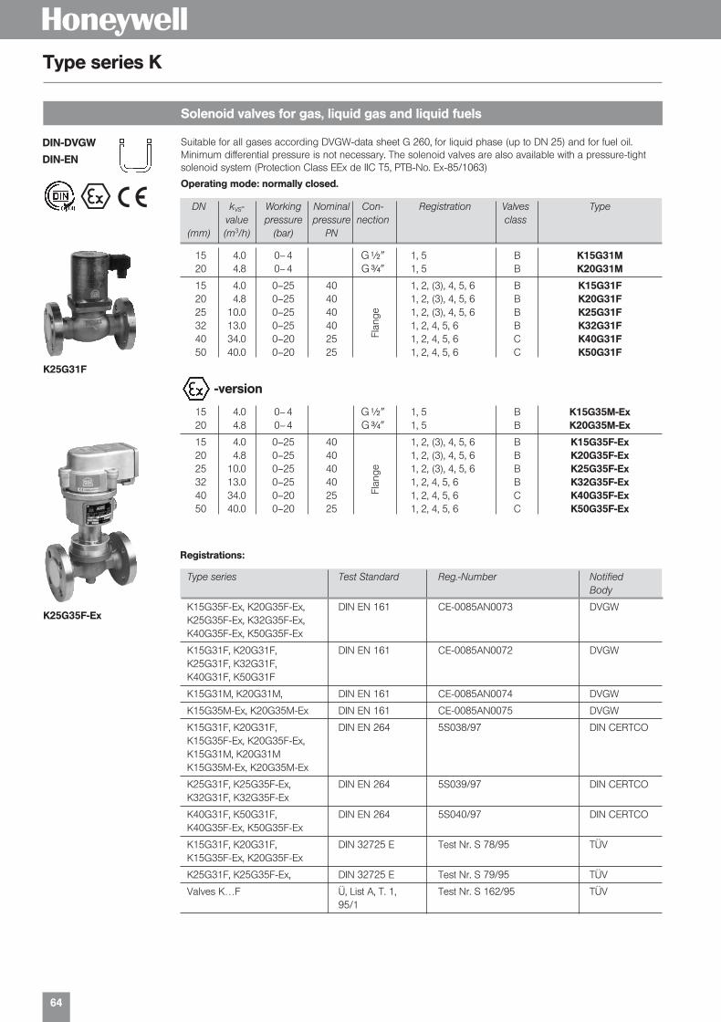
Solenoid valves for gas, liquid gas and liquid fuels
Type series K
Suitable for all gases according DVGW-data sheet G 260, for liquid phase (up to DN 25) and for fuel oil.Minimum differential pressure is not necessary. The solenoid valves are also available with a pressure-tightsolenoid system (Protection Class EEx de IIC T5, PTB-No. Ex-85/1063)
Operating mode: normally closed.
DN kVS- Working Nominal Con- Registration Valves Typevalue pressure pressure nection class
(mm) (m3/h) (bar) PN
15 4.0 0– 4 G|� 1, 5 B K15G31M20 4.8 0– 4 G}� 1, 5 B K20G31M
15 4.0 0–25 40 1, 2, (3), 4, 5, 6 B K15G31F20 4.8 0–25 40 1, 2, (3), 4, 5, 6 B K20G31F25 10.0 0–25 40 1, 2, (3), 4, 5, 6 B K25G31F32 13.0 0–25 40 1, 2, 4, 5, 6 B K32G31F40 34.0 0–20 25 1, 2, 4, 5, 6 C K40G31F50 40.0 0–20 25 1, 2, 4, 5, 6 C K50G31F
Flan
ge
15 4.0 0– 4 G|� 1, 5 B K15G35M-Ex20 4.8 0– 4 G}� 1, 5 B K20G35M-Ex
15 4.0 0–25 40 1, 2, (3), 4, 5, 6 B K15G35F-Ex20 4.8 0–25 40 1, 2, (3), 4, 5, 6 B K20G35F-Ex25 10.0 0–25 40 1, 2, (3), 4, 5, 6 B K25G35F-Ex32 13.0 0–25 40 1, 2, 4, 5, 6 B K32G35F-Ex40 34.0 0–20 25 1, 2, 4, 5, 6 C K40G35F-Ex50 40.0 0–20 25 1, 2, 4, 5, 6 C K50G35F-Ex
Flan
ge
-version
Registrations:
K25G35F-Ex
K25G31F
se
DIN-DVGW
DIN-EN
Type series Test Standard Reg.-Number Notified Body
K15G35F-Ex, K20G35F-Ex, DIN EN 161 CE-0085AN0073 DVGWK25G35F-Ex, K32G35F-Ex,K40G35F-Ex, K50G35F-Ex
K15G31F, K20G31F, DIN EN 161 CE-0085AN0072 DVGWK25G31F, K32G31F,K40G31F, K50G31F
K15G31M, K20G31M, DIN EN 161 CE-0085AN0074 DVGW
K15G35M-Ex, K20G35M-Ex DIN EN 161 CE-0085AN0075 DVGW
K15G31F, K20G31F, DIN EN 264 5S038/97 DIN CERTCOK15G35F-Ex, K20G35F-Ex,K15G31M, K20G31MK15G35M-Ex, K20G35M-Ex
K25G31F, K25G35F-Ex, DIN EN 264 5S039/97 DIN CERTCOK32G31F, K32G35F-Ex
K40G31F, K50G31F, DIN EN 264 5S040/97 DIN CERTCOK40G35F-Ex, K50G35F-Ex
K15G31F, K20G31F, DIN 32725 E Test Nr. S 78/95 TÜVK15G35F-Ex, K20G35F-Ex
K25G31F, K25G35F-Ex, DIN 32725 E Test Nr. S 79/95 TÜV
Valves K…F Ü, List A, T. 1, Test Nr. S 162/95 TÜV95/1
01331_Product Catalog_02 19.02.2002 9:29 Uhr Seite 64

65
H
Solenoid valves for medium temperature up to 180 °C
Type series TG-K
Solenoid valves for hot water and steam up to 120 °C/180°C
Type series LG
The piston-type solenoid valves of the TGK series are suitable for hot water, steam, fuel oil and othernon-aggressive media up to a temperature of 180 °C.Operating mode: normally closed, on desire normally open.
DN kVS-value Working pressure Internal Type(mm) (m3/h) (bar) thread
15 4.0 0–25 G|� T15G31MK20 4.8 0–25 G}� T20G31MK25 10.0 0–20 G 1 T25G31MK32 13.0 0–20 G 1[� T32G31MK
15 4.0 0–25 T15G31FK20 4.8 0–25 T20G31FK25 10.0 0–20 T25G31FK32 13.0 0–20 Flange T32G31FK40 34.0 0–16 T40G31FK50 40.0 0–16 T50G31FK
Tested to DIN 32730Fema piston-type solenoid valves of the LG series are particularly suitable for use as stop and safetycheck valves in heating installations up to 120 °C resp. 180 °C. The coupled (automatically servo-controlled) mode of operation does not require a minimum differential pressure; the units can open andclose perfectly even in the pressureless state and with low differential pressures.Operating mode: normally closed.
L25G31F
DN kVS-value Working pressure Internal Max. medium Type(mm) (m3/h) (bar) thread temperature
15 4.0 0–25 G|� L15G31M20 4.8 0–25 G}� L20G31M25 10.0 0–20 G 1 120 °C L25G31M32 13.0 0–20 G 1[� L32G31M
15 4.0 0–25 L15G31F20 4.8 0–25 L20G31F25 10.0 0–20 L25G31F32 13.0 0–20 Flange 120 °C L32G31F40 34.0 0–16 L40G31F50 40.0 0–16 L50G31F
15 4.0 0–20 G|� L15G31MK20 4.8 0–20 G}� L20G31MK25 10.0 0–16 G 1 180 °C L25G31MK32 13.0 0–16 G 1[� L32G31MK
15 4.0 0–20 L15G31FK20 4.8 0–20 L20G31FK25 10.0 0–16 L25G31FK32 13.0 0–16 Flange 180 °C L32G31FK40 34.0 0–12 L40G31FK50 40.0 0–12 L50G31FK
T40G31FK
Registration
Type series Test Standard Reg.-No. Notified Body
L15G31MK, L15G31FK, L20G31MK, L20G31FK DIN 32730 1F01999 DIN CERTCO
L25G31MK, L25G31FK, L32G31MK, L32G31FK DIN 32730 1F02099 DIN CERTCO
L40G31FK, L50G31FK DIN 32730 1F02199 DIN CERTCO
L15G31M, L15G31F, L20G31M, L20G31F DIN 32730 1F02299 DIN CERTCO
L25G31M, L25G31F, L32G31M, L32G31F DIN 32730 1F02399 DIN CERTCO
L40G31F, L50G31F DIN 32730 1F02499 DIN CERTCO
Valves L…F Ü, List A, T. 1, 95/1 Test No. TÜVS 160/95
01331_Product Catalog_02 19.02.2002 9:29 Uhr Seite 65

66
H
for valves
Accessories for Solenoid Valves
If not identified specially, the valves are delivered with “closed at zero current” mode of operation.Operating mode “open at zero current” (possible only for valves of the TG, TGK and TG-Ex series)
Sign
in normal versions (e. g. in TG and TGK) U
in Ex-version (type serie TG-Ex) U
Identification by additional letter “U”.
Ordering example: T25G31FU.
Operating mode
Special voltagesfor normal and Ex solenoids
Replacement solenoids
Rectifier/plug
Special voltages Ident.-No.
24 VDC 6
In the case of alternating voltages, a rectifier of corresponding capacity must be provided by the customer.
Ordering example: K 20 G 31 F6 (24 VDC).
Type
Device socket with built-in rectifier GSPrimary 230 VAC, 50 HzSecundary approx. ca. 230 VAC
Type
Normal version without rectifier, without plug G 31with device socket GS incl. rectifier G 31 GS(for 230 VAC)
Ex-versionwithout rectifier G 35-ExEx-version with rectifier (only for 230 VAC) G 35-Ex G
The suitable rectifiers are enclosed for all plunger solenoid valves which are ordered for 230 V.
01331_Product Catalog_02 19.02.2002 9:29 Uhr Seite 66

67
HType series GB
normally closed, also in stainless steel 1.4410This range of solenoid valves is of high quality and suitable for universal application, and is not dependent operationally on a specific minimum differential pressure; the valves operate correctlywith no pressure, at slight differential pressure, and right through to maximum pressure. They are there-fore the valves of choice for installation in plants where differential pressures fluctuate greatly andare not possible to determine precisely in advance. The valves are also suitable for use in heatingand cooling circuits.
DN kVS-value Pressure range Threaded Type(mm) (m3/h) (bar) connection
Brass valve body, internal parts stainless steel; Sealings: Perbunan (NBR)
12 2.8 0–16 G |� GB 1220 5.0 0–16 G }� GB 2025 10.0 0–16 G 1 GB 25
Stainless steel 1.4410 valve body, internal parts stainless steel; Sealings: Viton
12 2.8 0–16 G |� GB 12 VA20 5.0 0–16 G }� GB 20 VA25 10.0 0–16 G 1 GB 25 VA
Special voltages Ident.-No.
110 VAC 224 VAC 824 VDC 6ST 219: Device plug with LED-display for voltage 12 V – 24 VAC/DCST 220: Device plug with LED-display for voltage 100 V – 120 VAC/DCST 221: Device plug with LED-display for voltage 200 V – 240 VAC/DC
The AB-series are suitable for neutral media such as water and hydraulic oil. They operate withoutminimum differential pressure.
Medium temperature–10…+90 °C
Operating voltage230 VAC, 50 Hz
Vacuum resistance up to –0.9 bar.
DN kVS-value Pressure range Threaded Weight Type(m3/h) (bar) connections (kg)
Brass valve body, Membrane: Perbunan (NBR)
10 1.8 0–10 G #ß(� 0.4 AB1013 3.5 0–10 G |� 0.55 AB1320 8.6 0–10 G }� 1 AB2025 11 0–10 G 1� 1.7 AB2525 11 0–10 G 1[� 1.7 AB3240 30 0–10 G 1|� 3.5 AB4040 30 0–10 G 2� 3.5 AB50
Brass valve body, Sealing: Viton
10 1.8 -0.9–4 G #ß(� 0.4 AV102MS213 3.5 -0.9–4 G |� 0.55 AV131MS220 8.6 -0.9–10 G }� 1 AV201MS225 11 -0.9–10 G 1� 1.7 AV251MS225 11 -0.9–10 G 1[� 1.7 AV252MS240 30 -0.9–10 G 1|� 3.5 AV401MS240 30 -0.9–10 G 2� 3.5 AV402MS2
Device plugs see series GB.
Medium temperature–10…+90 °C (AB)0…+90 °C
SealingPerbunan (NBR)
Solenoid valves for gaseous and liquid media
Type series AB and AV
Solenoid valves for neutral liquid media normally closed
The solenoid valves series AV are designed for safety function in liquid fuel supply systems. The valves pre-vent unintended draining of the system and storage tanks in case of malfunction of burner or filter.
The Solenoid Valve series AVis designed for Safety func-tion in accordance with DINEN 264 (Registration No.5S235/2000) for Heatingliquid fuel EL supply systems.
01331_Product Catalog_02 19.02.2002 9:29 Uhr Seite 67

68
DN kVS-value Connect Materials Weight Type(mm) (m3/h) (kg)
13 3.7 G |� Ms 1.0 GK 1320 5.0 G }� Ms 1.4 GK 2025 10.0 G 1 Ms 1.9 GK 2532 16.0 G 1[� Ms 3.2 GK 3240 16.0 G 1|� Ms 3.7 GK 4050 36.0 G 2 Ms 7.8 GK 5025 10.0 Flange GG 25 4.6 GK 25 F32 16.0 Flange GG 25 7.0 GK 32 F40 16.0 Flange GG 25 7.5 GK 40 F50 36.0 Flange GG 25 12.8 GK 50 F
Solenoid valves for neutral media up to 180 °C
Type series GK
Type summary
Special voltages Ident.-No.
110 V, 50 Hz 224 V, 50 Hz 8
Ordering example for specially voltages 110 V, 50 Hz: GK 13-2
Technical dataVersion 2/2-way normally closedDesign Piston valve, balanced, no minimum pressure requiredMaterials Screwed version: brass
Flange version: cast iron GG 25Gasket material PTFE and graphiteMedia neutral media, e. g. hot water and steamMedium temperature 0–180 °CAmbient temperature max. 55 °COperating pressure 0–10 barViscosity max. 21 mm/sLine connection G |� up to G 2, Flange (PN 16) for DN 25–DN 50Operating voltages (± 10 %) 230 VAC, 50 Hz; 24 V, 50 Hz; 120 V, 60 HzDuty cycle 100 %Electrical connection Angled plug to DIN 43 650Power consumption start: 100 VA
operation: 35 VA, DN 50: 30 WDegree of protection IP 65Installation position preferably solenoid coil upwardsSwitching times opening(standard values) DN 15–DN 25: 100–400 ms
DN 32–DN 50: 200–1200 msclosingDN 15–DN 25: 300–500 msDN 32–DN 50: 1000–3000 ms
H
The GK series piston-type solenoid valves are ideal for use as shutoff valves in heating and processengineering systems for neutral media, e. g. hot water and steam. The valves require no minimum differential pressure.
01331_Product Catalog_02 19.02.2002 9:29 Uhr Seite 68

Accessories
H
01331_Product Catalog_02 19.02.2002 9:30 Uhr Seite 69

70
H
Programmable display
Type series AP
Digital LED display for 3-wire transmitters
Type series AZ
with 2 limit value switches for Pt 100 / Pt 1000 / or voltage and current signalsRoutines for setting the following parameters are integrated in the digital display which iscontrolled by a microprocessor:
■ Measuring range (starting and end point)
■ Display range (starting and end point)
■ Position of the decimal point
■ 2 limit values (relays) and their hysteresis
■ Drop-down or pull-in delay of the relays
■ Enquiry of the minimum and maximum measured value
■ Rounding up and down the last digit
■ Average formation
All routines and parameters can be set by keys on the front. The switching status of the relays isdisplayed by LEDs.
Input signals Display range Suitable Type(programmable) (programmable) for
0–1 VDC –1999 to +1999 Pressure and APV 6300–10 VDC temperature0–20 mA DC transmitter
Pt 100/Pt 1000 –150 °C to +199.9 °C Temperature APT 650–200 °C to +800 °C sensors
Pt 100/Pt 1000
Type summary
Type
3-wire-System AZ 331
Display 3||-digit –1999…+1999
Input signalsFreely selectable by settingjumpers. See type summary.
Housing front48 x 96 mm (DIN)
Actual value display3|-digit, LED 12.5 mm, red,automatic “–”-sign.
Programmable switchingoutputs2 changeover switches
Output relay switchingcapacity2 x 230 VAC, 5 A AC
Supply voltage230 V, 50–60 Hz, 3 VA
Degree of protection(front)IP 60, DIN 40 050
Working temperature–10 to +50 °C.
With the display module AZ, the output of a transmitter from the MODUFLEX system is made visible ona LED display.
The starting and end value of the display can be adjusted between –1999 and +1999, so that an arbitrary display range can be assigned to any pressure range. The decimal point can be switched overwith a slide switch.
The y signals of the transmitter can thus be displayed in any arbitrary unit, e. g. V, mA, bar, mbar, %, psi,°C, m, cm (filling height), m3 , cm3 (volume) etc.
In addition the display module in its condition on delivery (factor setting 0–10.00) is suitable for theaccurate adjustment of the working range of a transmitter.
DisplayLED-display, 7 mm high
Display range–1999…+1999
Supply voltage24 VAC or 24 VDC From the basic module byribbon cable.
Signal voltage: (input) 0–10 V Signal inputthrough ribbon cable fromthe evaluation module orfrom other modules /wire-system. ■ for pressure transmitter serie F
■ for pressure transmitter serie SN 3■ for start-up and service (factory setting 0–10.00)
01331_Product Catalog_02 19.02.2002 9:30 Uhr Seite 70

71
HType series VKD
For differential pressure switches DDCM 014 to DDCM 16 and for differential pressure transmitters serieFHBN…
Technical dataPressure stage PN 420Material housing high-grade steel 1.4404
inside high-grade steel 1.4571Sealings PTFEConnections |–14 NPTIncluded in delivery valves, screws and tube
Type summary
Type
3-venting valves VKD 35-venting valves VKD 5
The 5-fold combination contains 2 additional venting valves. The valve combinations are also availablefree of oil and grease on special request.
VKD 3
for installation of the thermostats and pressure switches in explosion endangered roomsIntrinsically safe control commands can be transferred to non-intrinsically safe active circuits with theisolating switching amplifiers. Thus it is possible to use pressure and temperature switches in explosionendangered areas (≥ zone 1).
The isolating switching amplifier must be installed outside the Ex zone.
Ex 041The Ex 041 isolating switching amplifier is designed additionally in safety technology. The leads between the isolating switching amplifier and pressure or temperature switch are monitored for wirebreakage and short circuit. The pressure switch must therefore be equipped with a resistor combination
Type summaryEx 011
Ex 041
VKD 5
Application Suitable Equipment Typefor optional functions
Suitable for all pressure and 201, 203, 205, 206, Without short Ex 011temperature switches with 301, 213, 513 circuit monitoringmicroswitches and proximityswitches
Isolating switching amplifier in 574, 575, 576, 577, With wire breakage Ex 041safety technology. Suitable for FD 16… and short circuitmaximum pressure limiting monitoringdevices with resistor combinationand for the pressure limitingdevices FD… and DBS
Shut-off valve combinations for differential pressure
Type series Ex V
Isolating switching amplifier
01331_Product Catalog_02 19.02.2002 9:30 Uhr Seite 71

72
H
MAU 8 / Nst
Siphons to DIN 16282 made of seamless steel tube 20 mm Ø
Siphons
Male adapter union for differential pressure switches and transmitters
Type series MAU
FORM B Material Type
Inlet: Weld-on end with weld chamfer St 35.8-l U 430 BOutlet: Connection shank DIN 16 282 Form 6 1.4571 U 480 BG|� with clamping sleeve DIN 16 283 G|�
Type summary
Body O-Ring Type
G[�-external thread Brass NBR MAU 8/MSwith O-ring seal for Stainlessconnection of pipes with steel FPM MAU 8/Nst8 mm outside diameter (1.4571)
FORM D Material Type
Inlet: Weld-on end with welding bevel St 35.8-l K 430 DOutlet: Connection shank DIN 16 282 Form 6 1.4571 K 480 DG|� with clamping sleeve DIN 16 283 G|�
Description Type
NPT adapter, material 1.4104 and sealing ring DIN 16 258, NPT 1Form C material ITC to DIN 3754 T.1
NPT adapterThe purpose of the NPT adapter is to connect pressure switches, pressure transmitters, pressure gauges, etc., to NPT threaded connections. A suitable sealing washer is also supplied.
Material Type
Ms DMW (Water)
Pressure surge reducer
Male adapter union G[� / 8 mm for adaption of:■ differential pressure switches DDCM■ pressure switches with [� internal thread
Maximum permissible temperature: 100 °CMaximum permissible pressure: 100 barConsider maximum pressure of the pressure switches / pressure transmitters.
U-shape (FORM B)
Circlar (FORM D)
NPT adapter
Pressure surge reducer
all measures in mm
MAU 8 / Ms
01331_Product Catalog_02 19.02.2002 9:30 Uhr Seite 72

73
H
for thermostats and pressure switches
Accessories, spare parts
Wall bracket H 1including fixing screws and plugs (6 mm Ø)Included as standard with Type TRM thermostats. Suitable for allswitching units.
Wall bracket H 2for fixing the sensor cartridges of capillary tube thermostats.Suitable for all Type TAM capillary tube thermostats.
Capillary tube holder H 3to attach the capillary tube of frost protection thermostats to the frame ofthe air heater (5 off packed in bag).Suitable for FT frost protection thermostats and frost protection FTS.
Sealing P 2consists of cover plate and screw for coveringand sealing the adjustment screws.Only for switching device 200 (plug connection)
Heating conducting compound WLP 1to improve the transfer of heat, e. g. in the case of contact thermostats.Approx. 0.5 cm3 in handy dispenser.
Capillary tube bushing R 4with 3 mm capillary tube (not pressure proof)screw in thread G|� suitable for all types TAM, FT and FTS.
Capillary tube bushing R 5Rubber plug for 3 mm capillary tube, bore diameter 10 mm.Not pressure proof (5 pieces in one bag).Suitable for series TA, FT and FTS.
Plug to DIN 43650 ST 5for switching units of series 200. with seal and fastening screw,3-pole + earth contact.
Plug to DIN 43650, ST 3Can be opened for easy installation,3-pole + earth contact, including sealings.
Plug connectors with position indication ST 218Operating voltage: 12–240 VAC/DCOperating current: max. 2 ALED current drain: max. 10 mALED indication: green if voltage present at contact pin 1
red if voltage present at contact pin 2Connection rotatable 270° engaging at increments of 45°Degree of protection: IP 65Ambient temperature: 0–60 °CSuitable for pressure and temperature switches with plug connection(series 200) which are equipped with a microswitch (standard version).
Plug, can be opened (0–10 V). ST 7–3Suitable only for transmitters (low voltage), 3 pin.Version for 4–20 mA ST 7–2
Type
ST 7
01331_Product Catalog_02 19.02.2002 9:30 Uhr Seite 73
74
H
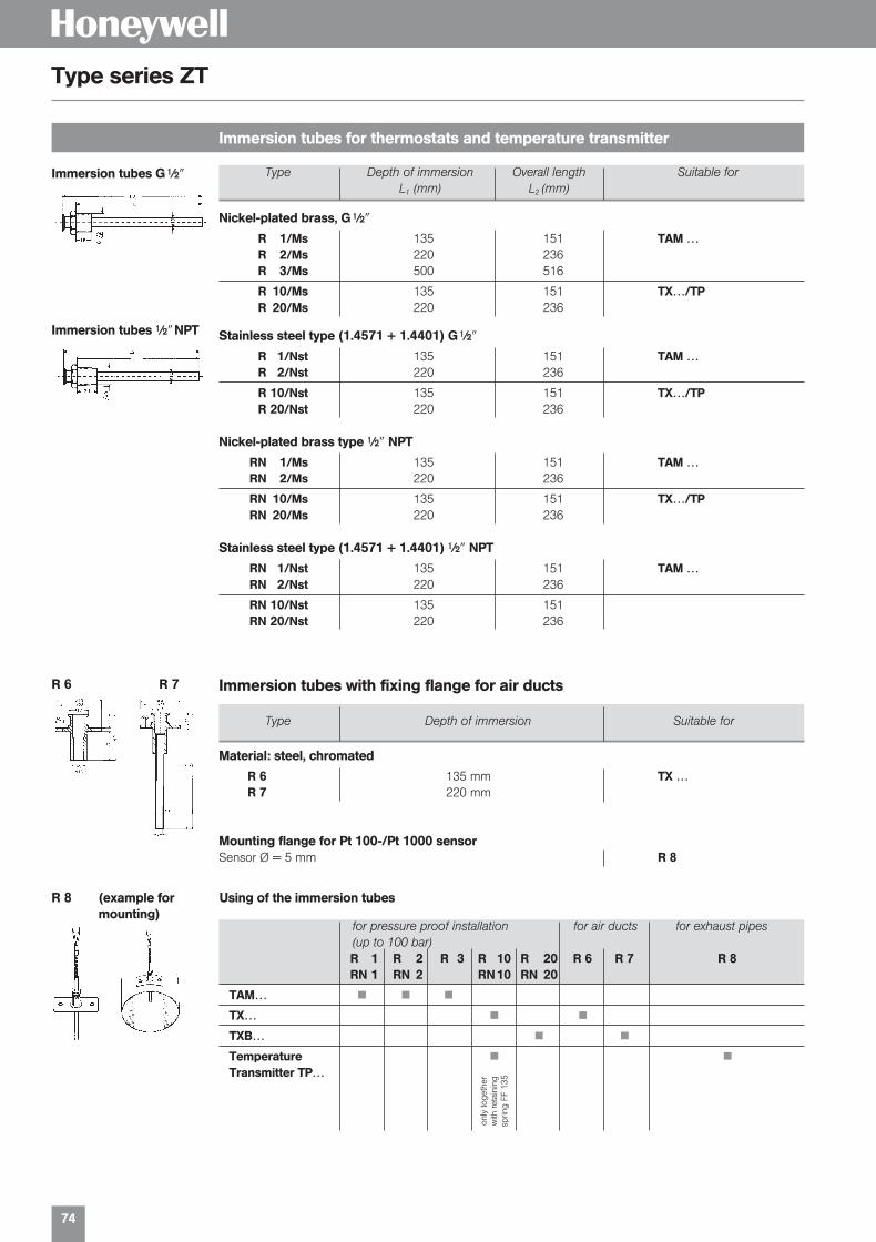
Immersion tubes for thermostats and temperature transmitter
Type series ZT
for pressure proof installation for air ducts for exhaust pipes(up to 100 bar)R 1 R 2 R 3 R 10 R 20 R 6 R 7 R 8RN 1 RN 2 RN 10 RN 20
TAM… ■ ■ ■
TX… ■ ■
TXB… ■ ■
Temperature ■ ■
Transmitter TP…
Type Depth of immersion Overall length Suitable forL1 (mm) L2 (mm)
Nickel-plated brass, G ||�
R 1/Ms 135 151 TAM …R 2/Ms 220 236R 3/Ms 500 516
R 10/Ms 135 151 TX…/TPR 20/Ms 220 236
Stainless steel type (1.4571 + 1.4401) G ||�
R 1/Nst 135 151 TAM …R 2/Nst 220 236
R 10/Nst 135 151 TX…/TPR 20/Nst 220 236
Nickel-plated brass type ||� NPT
RN 1/Ms 135 151 TAM …RN 2/Ms 220 236
RN 10/Ms 135 151 TX…/TPRN 20/Ms 220 236
Stainless steel type (1.4571 + 1.4401) ||� NPT
RN 1/Nst 135 151 TAM …RN 2/Nst 220 236
RN 10/Nst 135 151RN 20/Nst 220 236
Material: steel, chromated
R 6 135 mm TX …R 7 220 mm
Mounting flange for Pt 100-/Pt 1000 sensorSensor Ø = 5 mm R 8
Type Depth of immersion Suitable for
Immersion tubes with fixing flange for air ducts
only
toge
ther
with
ret
aini
ngsp
ring
FF 1
35
R 8 (example for Using of the immersion tubesmounting)
R 6 R 7
Immersion tubes G ||�
Immersion tubes ||� NPT
01331_Product Catalog_02 19.02.2002 9:30 Uhr Seite 74
75
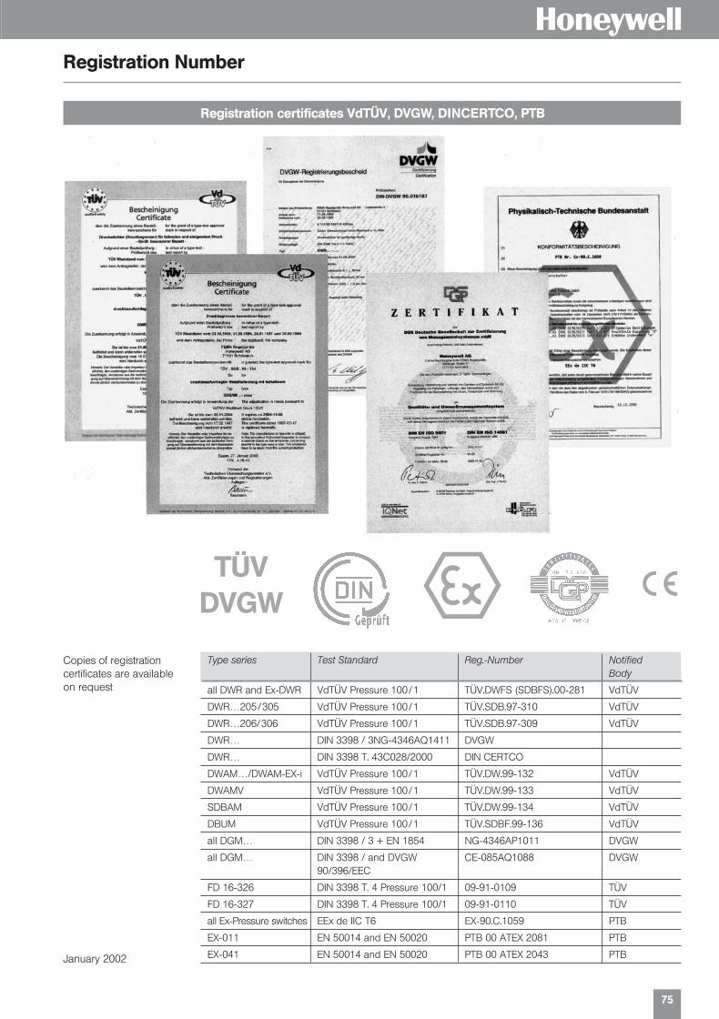
HRegistration Number
Registration certificates VdTÜV, DVGW, DINCERTCO, PTB
Type series Test Standard Reg.-Number NotifiedBody
all DWR and Ex-DWR VdTÜV Pressure 100/1 TÜV.DWFS (SDBFS).00-281 VdTÜV
DWR…205/305 VdTÜV Pressure 100/1 TÜV.SDB.97-310 VdTÜV
DWR…206/306 VdTÜV Pressure 100/1 TÜV.SDB.97-309 VdTÜV
DWR… DIN 3398 / 3NG-4346AQ1411 DVGW
DWR… DIN 3398 T. 43C028/2000 DIN CERTCO
DWAM…/DWAM-EX-i VdTÜV Pressure 100/1 TÜV.DW.99-132 VdTÜV
DWAMV VdTÜV Pressure 100/1 TÜV.DW.99-133 VdTÜV
SDBAM VdTÜV Pressure 100/1 TÜV.DW.99-134 VdTÜV
DBUM VdTÜV Pressure 100/1 TÜV.SDBF.99-136 VdTÜV
all DGM… DIN 3398 / 3 + EN 1854 NG-4346AP1011 DVGW
all DGM… DIN 3398 / and DVGW CE-085AQ1088 DVGW90/396/EEC
FD 16-326 DIN 3398 T. 4 Pressure 100/1 09-91-0109 TÜV
FD 16-327 DIN 3398 T. 4 Pressure 100/1 09-91-0110 TÜV
all Ex-Pressure switches EEx de IIC T6 EX-90.C.1059 PTB
EX-011 EN 50014 and EN 50020 PTB 00 ATEX 2081 PTB
EX-041 EN 50014 and EN 50020 PTB 00 ATEX 2043 PTB
TÜVDVGW e s
Copies of registration certificates are availableon request
January 2002
01331_Product Catalog_02 19.02.2002 9:30 Uhr Seite 75

s
Fema ControlsHoneywell AGBöblinger Strasse 17D-71 101 Schönaich Phone (49) 70 31 6 37-02Fax (49) 70 31 6 37-8 50E-Mail [email protected]://www.honeywell.de/fema
EN3B-0266GE51 R0202 Subject to change without notice. © 2001 Honeywell AG
L o c a l F e m a P a r t n e r s i n E u r o p e ,
M i d d l e E a s t , A f r i c a a n d A s i a P a c i f i c
LONM
AR
K®
and
the
LO
NW
OR
KS
® lo
go a
re r
egis
tere
d t
rad
emar
ks o
f the
Ech
elon
cor
por
atio
n.
AustriaFranz Schmachtl KGPummererstraße 364021 LinzPhone: (43) 7 32 76 46-0Fax: (43) 7 32 78 50 36
BelgiumERIKS N. V.Boombekelaan 32660 HobokenPhone: (32) 3-8 29 26 11Fax: (32) 3-8 28 39 59
BulgariaHoneywell EOOD14, Iskarsko ChausseePOB 791592 SofiaPhone: (359) 2 79 40 27Fax: (359) 2 79 40 90
Czech. RepublicHoneywell spol s r. o.Budejovicka 114021 Prague 4Phone: (420) 2 61 12 27 77Fax: (420) 2 61 12 26 91
DenmarkGRANZOW A/SEjby Industrievej 262600 GlostrupPhone: (45) 43 20 26 00Fax: (45) 43 20 26 99
FinlandHoneywell OYRuukintje 802320 Espoo 32Phone: (358) 93 48 01 01Fax: (358) 9 34 80 12 34
FranceBürkert & Contromatic FranceB.P. 2167220 Triembach au ValPhone: (33) 3.88.58.91.11Fax: (33) 3.88.57.20.08
GreeceHoneywell EPE313 Irakliou Ave./1-3 Viotias Str.Neon Iraklion – AthensPhone: (30) 12 84 80 49Fax: (30) 12 84 80 55
HungaryHoneywell Kft.Gogol u. 131133 BudapestPhone: (36) 14 51 43 00Fax: (36) 14 51 43 43
ItalyHoneywell S.p.A.Via Gobetti, 2b20063 Cernusco sul NaviglioPhone: (39) 02 92 14 61Fax: (39) 02 92 1468 88
NetherlandsERIKS B.V.Postbus 2801800 BK AlkmaarPhone: (31) 72 5 14 15 14Fax: (31) 72 5 15 56 45
NorwayBürkert-Contromatic A/SBox 2432026 SkjettenPhone: (47) 63-84 44 10Fax: (47) 63-84 44 55
PolandHoneywell sp. z.o.o.ul. Domaniewska 41(Budynek Mars)02-672 WarsawPhone: (48) 2 26 06 09 00Fax: (48) 2 26 06 09 01
PortugalHoneywell Portugal LdaEdificio Suecia IIAv do Forte Nr. 3 - Piso 32795 CarnaxidePhone: (351) 2 14 24 50 00Fax: (351) 2 14 24 50 99
RomaniaHoneywell Romania S.R.L.Blvd.Dacia No. 85Ap.9, sector 270256 BucharestPhone: (40) 12 11 00 76Fax: (40) 12 10 33 75
RussiaHoneywell Inc.4th floor, Administrative Bldg. of AO "Luzhniki" ManagementLuzhniki 24119048 MoscowPhone: (7) 09 57 96 98 00/01Fax: (7) 09 57 96 98 93/92
Slovak RepublicHoneywell LtdMlynske Nivy 73PO Box 7582007 Bratislava 27Phone: (421) 7 58 24 74 00/425Fax: (421) 7 58 24 74 15
SpainHoneywell S.A.Josefa Valcárcel, 2428027 MadridPhone: (34) 9 13 13 61 00Fax: (34) 9 13 13 61 27
SwedenBürkert-Contromatic ABSkeppsbron 13 B21120 MalmoePhone: (46) 40 6 64 51 00Fax: (46) 40 6 64 51 01
SwitzerlandTRI-MATIC AGBösch 826331 HünenbergPhone: (41) 41 7 80 22 22Fax: (41) 41 7 80 03 60
TurkeyHoneywell Otomasyon Ve KontrolSistemleri San. Ve Tic. A.S. Cayiryolu Sok. (Halyolu)Ucgen Plaza No: 7, Kat 5-6-7Icerenkoy 81120 / Istanbul Phone: (90) 21 64 64 47 74Fax: (90) 21 64 64 47 94
UkraineHoneywellZhelyabova 8/403680 KievPhone: (38) 04 42 41 91 95Fax: (38) 2 41 91 96
United KingdomBürkert Contromatic Ltd.Fluid Control CentreBrimscombe Port, Bus. ParkBrimscombe Stroud,Glos GL5 2QFPhone: (44) 14 53 73 13 53Fax: (44) 14 53 73 13 43
Middle East HeadquartersHoneywell Middle East Ltd. Khalifa St.Sheikh Faisal BuildingAbu Dhabi, United Arab EmiratesPhone: (971) 26 27 25 33Fax: (971) 26 26 95 39
Distributors & Africa HeadquartersHoneywell S.p.A.International OperationsVia Gobetti, 2b20063 Cernusco sul NaviglioPhone: (39) 2 92 14 61Fax: (39) 2 92 14 68 88
South AfricaWIKA INSTRUMENTS (Pty.) Ltd.P.O. Box 75225 Gardenview 2047Phone: (27) 11-621-0000Fax: (27) 11-621-0049
Asia Pacific HeadquartersHoneywell Pte Ltd.Honeywell Building17 Changi Business Park Central 1Singapore 486073Republic of SingaporePhone: (65) 35 50 28 28Fax: (65) 4 45 30 33
H
f
01331_Product Catalog_02 19.02.2002 9:30 Uhr Seite 76