LogTag TRED30-7 Vaccine Monitoring Data Logger kit Start-up …€¦ · · 2018-01-05LogTag...
42
Presented by Control Solutions 1 (888) 311‐0636 LogTag TRED30-7 Vaccine Monitoring Data Logger kit Start-up instructions Slide 1
Transcript of LogTag TRED30-7 Vaccine Monitoring Data Logger kit Start-up …€¦ · · 2018-01-05LogTag...
Presented byControl Solutions1 (888) 311‐0636
LogTag TRED30-7 Vaccine Monitoring Data Logger kit Start-up instructions
Slide 1

When you receive your LogTag TRED30‐7 Vaccine Monitoring Kit Everything you need is included to get started.
The Kit includes:LogTag TRED30‐7R data loggerStainless steel temperature sensor with 4’ of cable in a shatter‐proof glycol filled bottleAcrylic stand so your glycol bottle can stand up in the fridge or freezer, eliminates unwanted oscillations of temperatures.Mounting bracket to be attached to the side or front of your fridge/freezerInstallation Kit‐ Adhesive backed cable tie mounts with tie wraps so you can secure the cable to the side of the fridge/freezerOne extra battery. The data logger comes with a battery installed (put the extra battery in a secure spot so you can find it in approx. 1 year)NIST traceable Certificate of Calibration compliant to ISO 17025;2005CD with instructions for start‐up
Slide 2

Your LogTag TRED30‐7R Vaccine Monitoring kit includes the following:
Slide 3
Contents
Step 1: Installing the probe in the fridge/freezerStep 2: Software downloadStep 3: User profile set‐upStep 4: LogTag data logger configurationStep 5: Operation of the LogTag
Slide 4
STEP 1
Install the Probe in the fridge/freezer
Slide 5
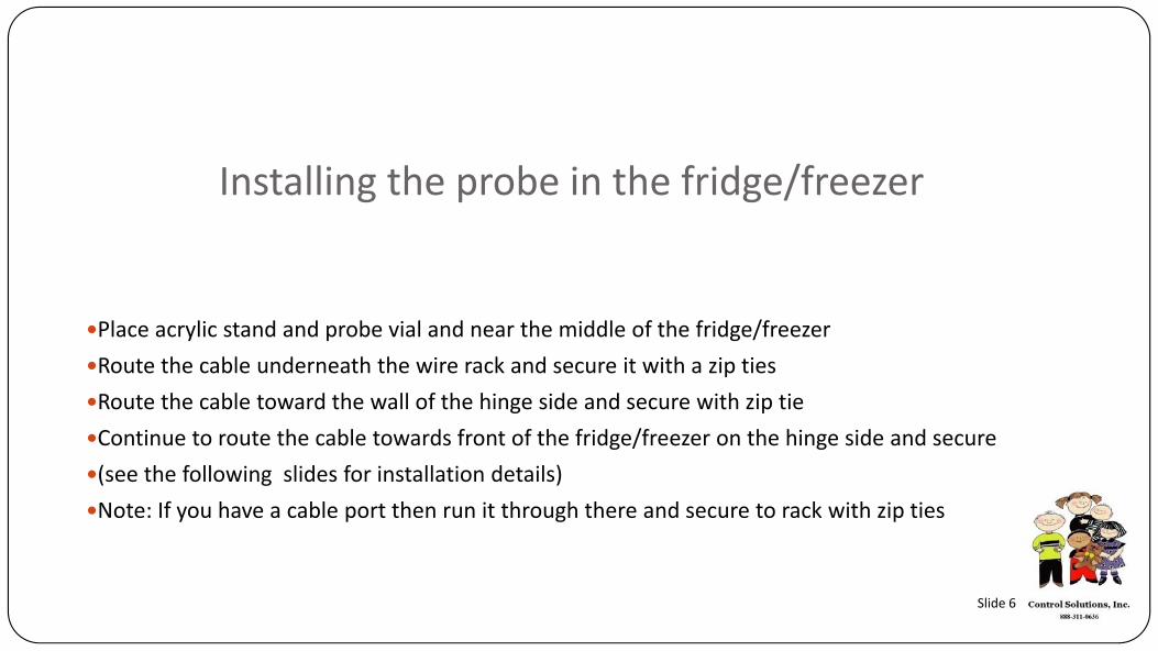
Installing the probe in the fridge/freezer
Place acrylic stand and probe vial and near the middle of the fridge/freezerRoute the cable underneath the wire rack and secure it with a zip tiesRoute the cable toward the wall of the hinge side and secure with zip tieContinue to route the cable towards front of the fridge/freezer on the hinge side and secure (see the following slides for installation details)Note: If you have a cable port then run it through there and secure to rack with zip ties
Slide 6
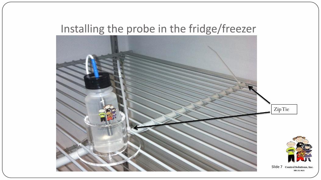
Installing the probe in the fridge/freezer
Zip Tie
Slide 7
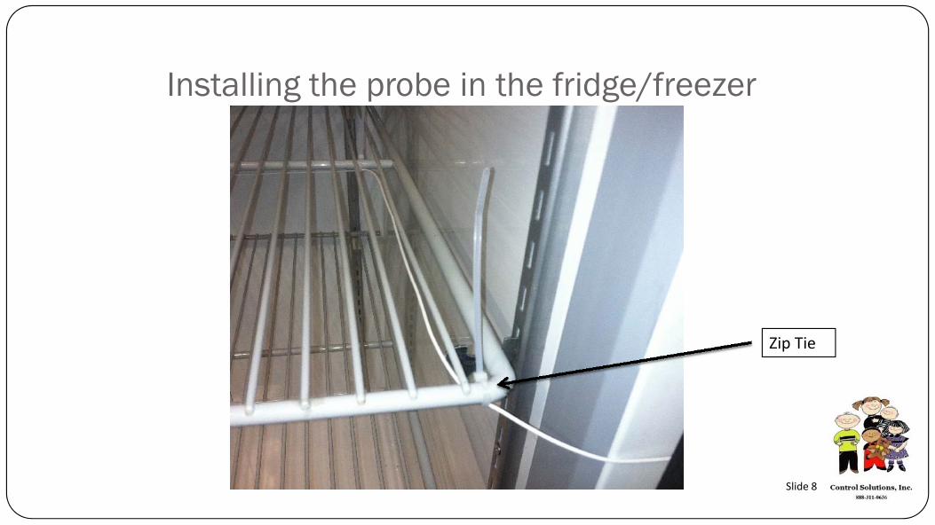
Installing the probe in the fridge/freezer
Zip Tie
Slide 8
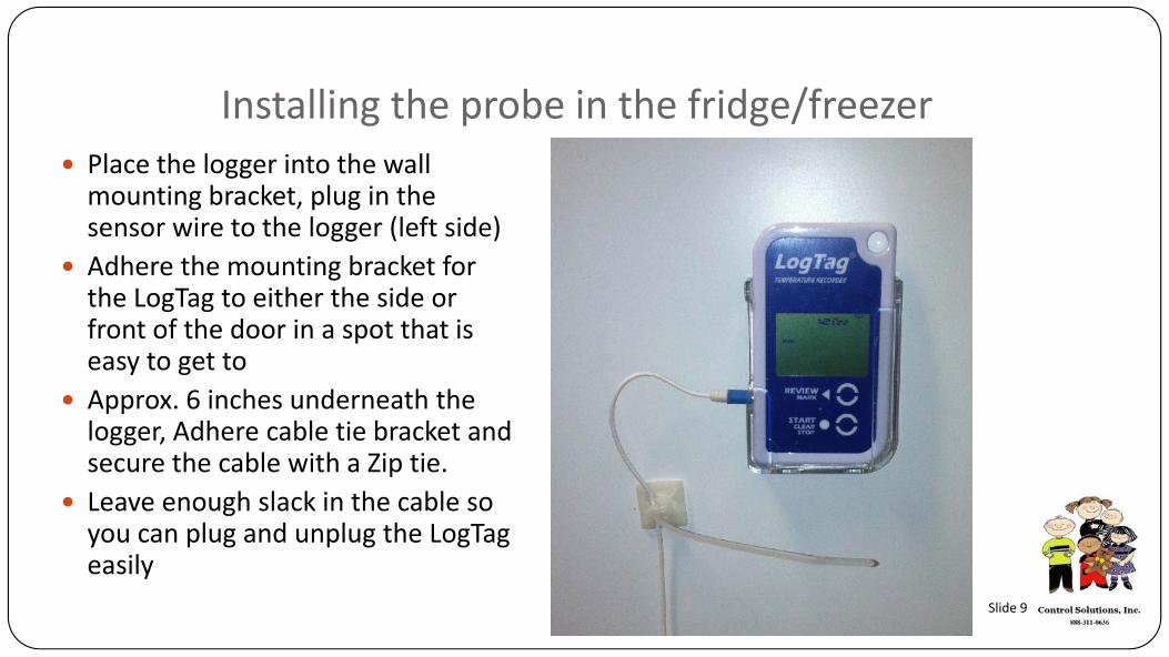
Installing the probe in the fridge/freezerPlace the logger into the wall mounting bracket, plug in the sensor wire to the logger (left side)Adhere the mounting bracket for the LogTag to either the side or front of the door in a spot that is easy to get toApprox. 6 inches underneath the logger, Adhere cable tie bracket and secure the cable with a Zip tie.Leave enough slack in the cable so you can plug and unplug the LogTageasily
Slide 9
STEP 2
Software Download
Slide 10

Downloading the software
Click the link on our website www.vfcdataloggers.com to download the software.
Slide 11Note: The software is also located on the mini CD in your docking station box.
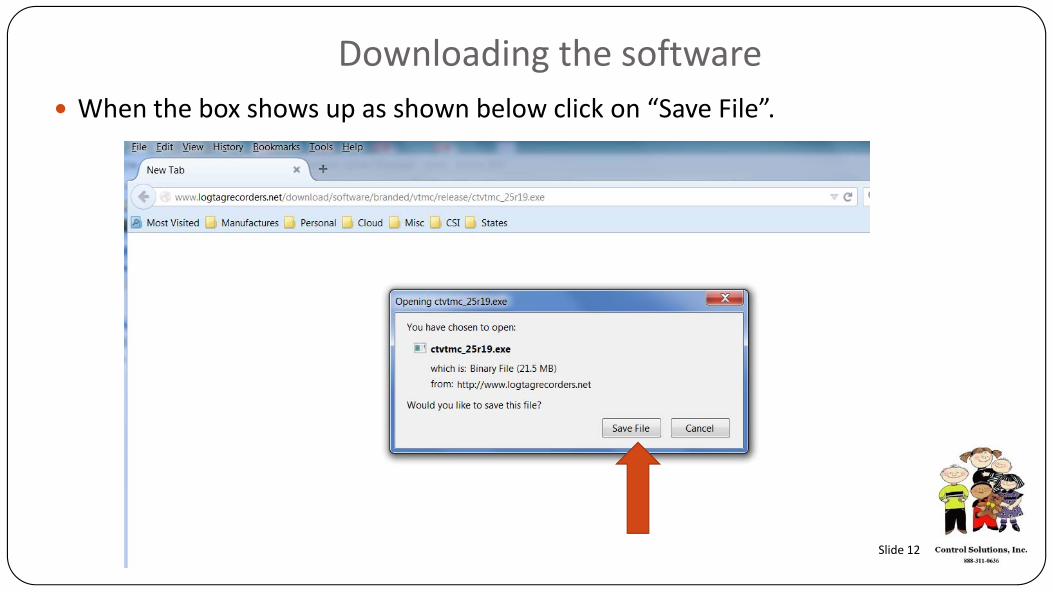
Downloading the softwareWhen the box shows up as shown below click on “Save File”.
Slide 12

Downloading the softwareGo to where you saved the file to and click on the file to start the download. You will need administrations rights to do this and may need IT support
Slide 13
Downloading the software
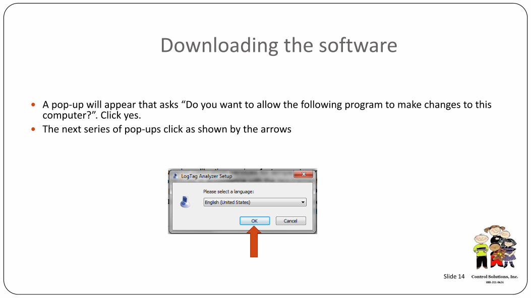
A pop‐up will appear that asks “Do you want to allow the following program to make changes to this computer?”. Click yes.The next series of pop‐ups click as shown by the arrows
Slide 14
Downloading the software
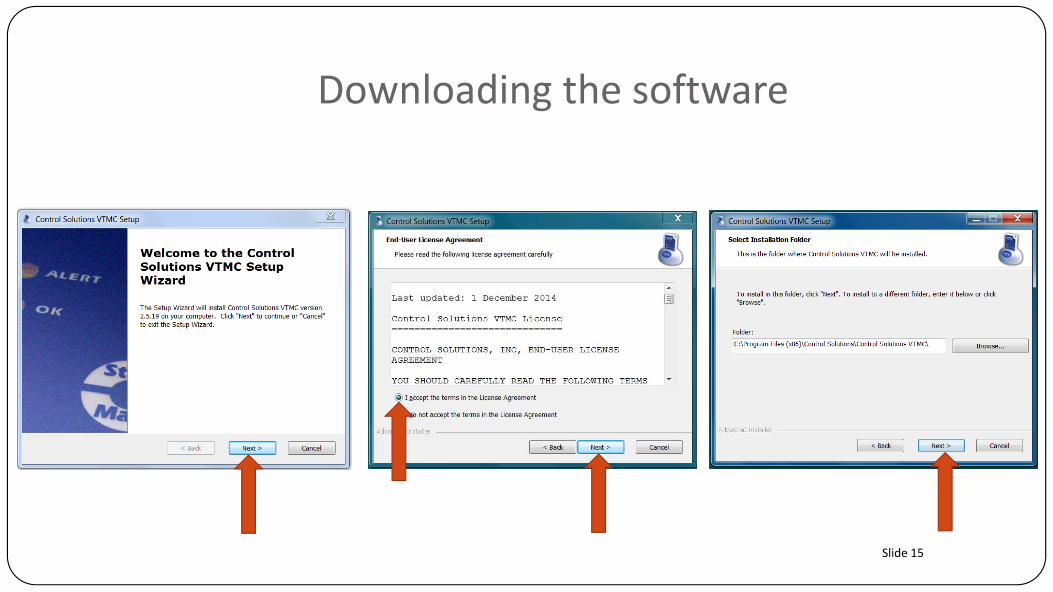
Slide 15
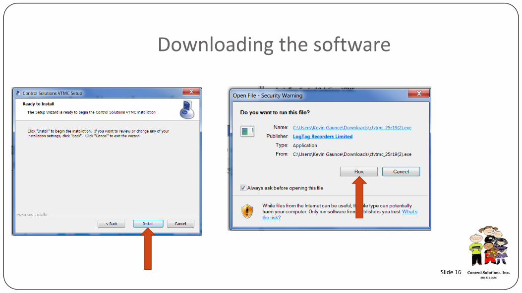
Downloading the software
Slide 16

Downloading the softwareYou should now have an icon on your desktop that looks like this.
Slide 17

STEP 3
User Profile Set‐up Configuration
Slide 18
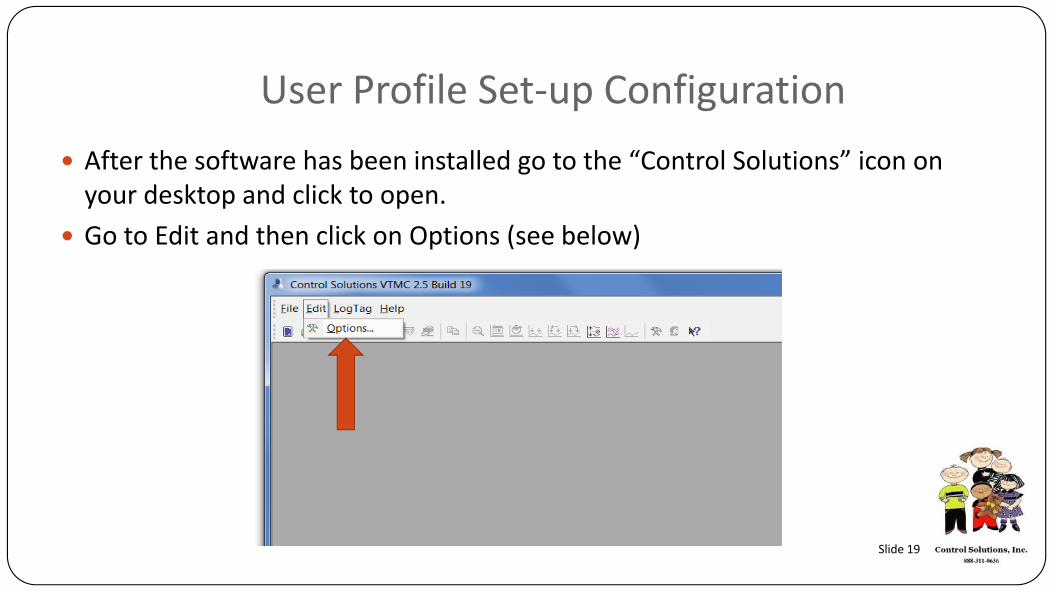
User Profile Set‐up ConfigurationAfter the software has been installed go to the “Control Solutions” icon on your desktop and click to open.Go to Edit and then click on Options (see below)
Slide 19

User Profile Set‐up ConfigurationClick on “General Settings” and then select the following
Select °F or °C. This will be how the temp will be displayed in your software
Slide 20
User Profile Set‐up Configuration
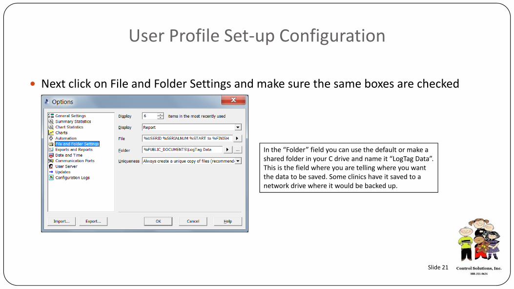
Next click on File and Folder Settings and make sure the same boxes are checked
In the “Folder” field you can use the default or make a shared folder in your C drive and name it “LogTag Data”. This is the field where you are telling where you want the data to be saved. Some clinics have it saved to a network drive where it would be backed up.
Slide 21

User Profile Set‐up ConfigurationThe remanding Option selections do not require changes. Click “OK”. To complete
Slide 22
STEP 4
LogTag Data Logger Configuration
Note: Pre‐configuration is a service we provide at no charge. We can pre‐configure for either a refrigerator or freezer. We will also mark the box accordingly. You will only need to edit “User ID” (Logger name)
Slide 23

LogTag Data Logger Configuration Make sure your LogTag software is open on your PCNow plug your Docking Station into the USB port on your PCInsert data logger into the Docking Station
Docking Station
Slide 24
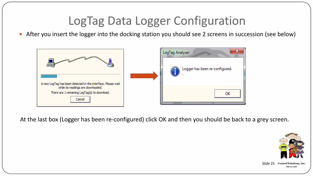
LogTag Data Logger Configuration After you insert the logger into the docking station you should see 2 screens in succession (see below)
At the last box (Logger has been re‐configured) click OK and then you should be back to a grey screen.
Slide 25
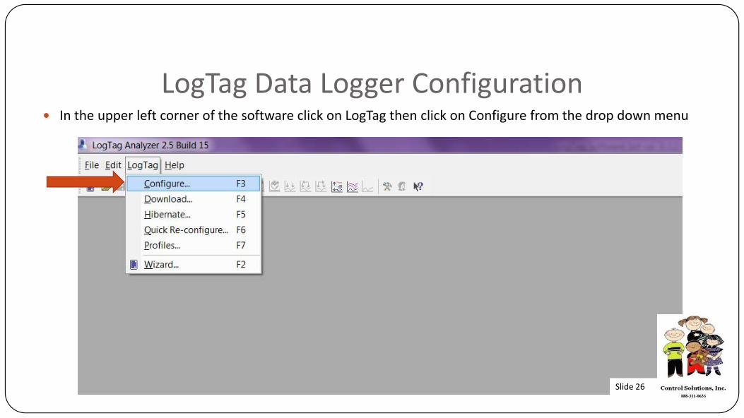
LogTag Data Logger ConfigurationIn the upper left corner of the software click on LogTag then click on Configure from the drop down menu
Slide 26
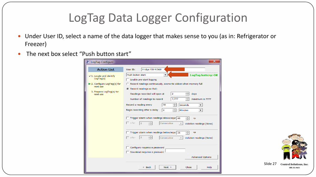
LogTag Data Logger ConfigurationUnder User ID, select a name of the data logger that makes sense to you (as in: Refrigerator or Freezer)The next box select “Push button start”
Slide 27
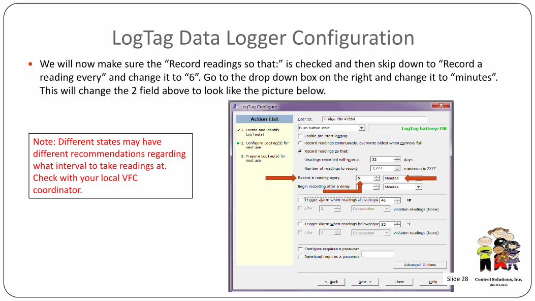
LogTag Data Logger ConfigurationWe will now make sure the “Record readings so that:” is checked and then skip down to “Record a reading every” and change it to “6”. Go to the drop down box on the right and change it to “minutes”. This will change the 2 field above to look like the picture below.
Note: Different states may have different recommendations regarding what interval to take readings at. Check with your local VFC coordinator.
Slide 28

LogTag Data Logger ConfigurationNext we will configure our alarms. Our example shows Deg F but it can be in Deg C as well. First click on the “Trigger alarm when readings are above/equal” and set that for 46 Deg F (this would be for a refrigerator). Next click on “After” and type in “5”. Then click the drop down box to the right and select “Consecutive”. We will do the same for the lower alarm but we will have it at 35 Deg F and 2 consecutive as shown below.
Slide 29
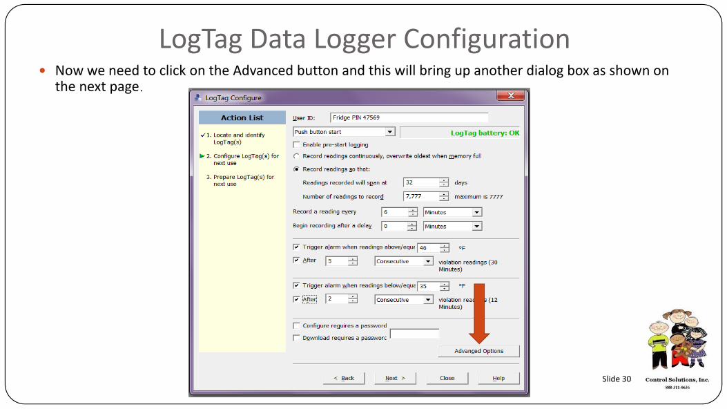
LogTag Data Logger ConfigurationNow we need to click on the Advanced button and this will bring up another dialog box as shown on the next page.
Slide 30

LogTag Data Logger ConfigurationCheck the boxes as shown below and then click OK.
Note: Select Fahrenheit or Celsius for how you want your logger to display temperature.
Slide 31
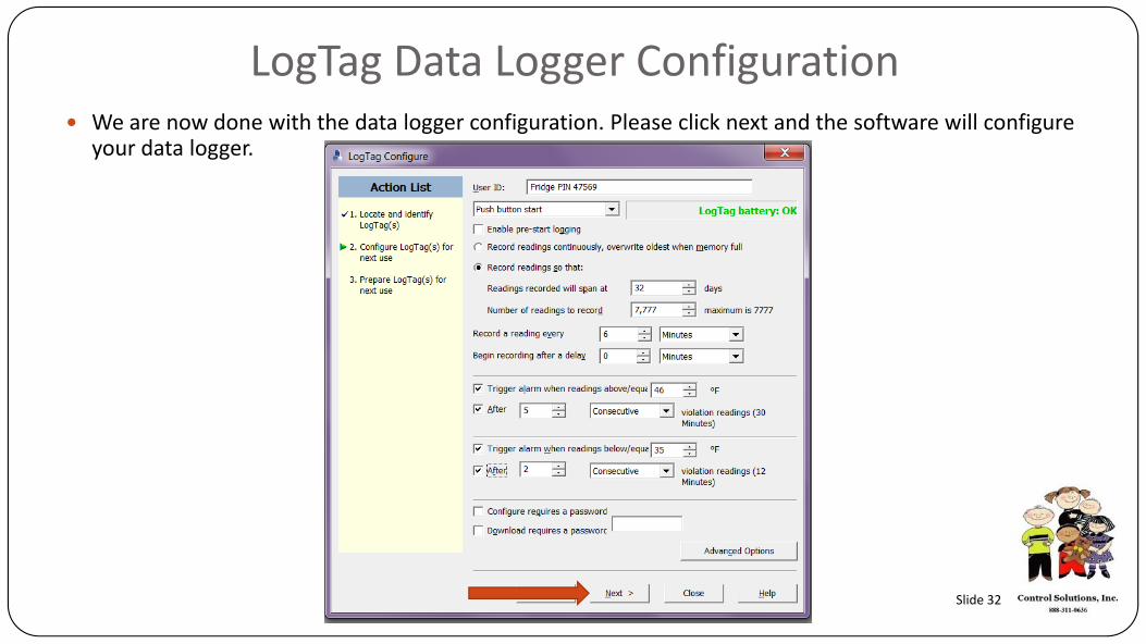
LogTag Data Logger ConfigurationWe are now done with the data logger configuration. Please click next and the software will configure your data logger.
Slide 32
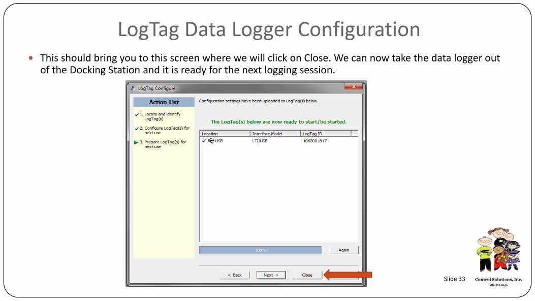
LogTag Data Logger ConfigurationThis should bring you to this screen where we will click on Close. We can now take the data logger out of the Docking Station and it is ready for the next logging session.
Slide 33
STEP 5
Operation of your LogTag
Slide 34
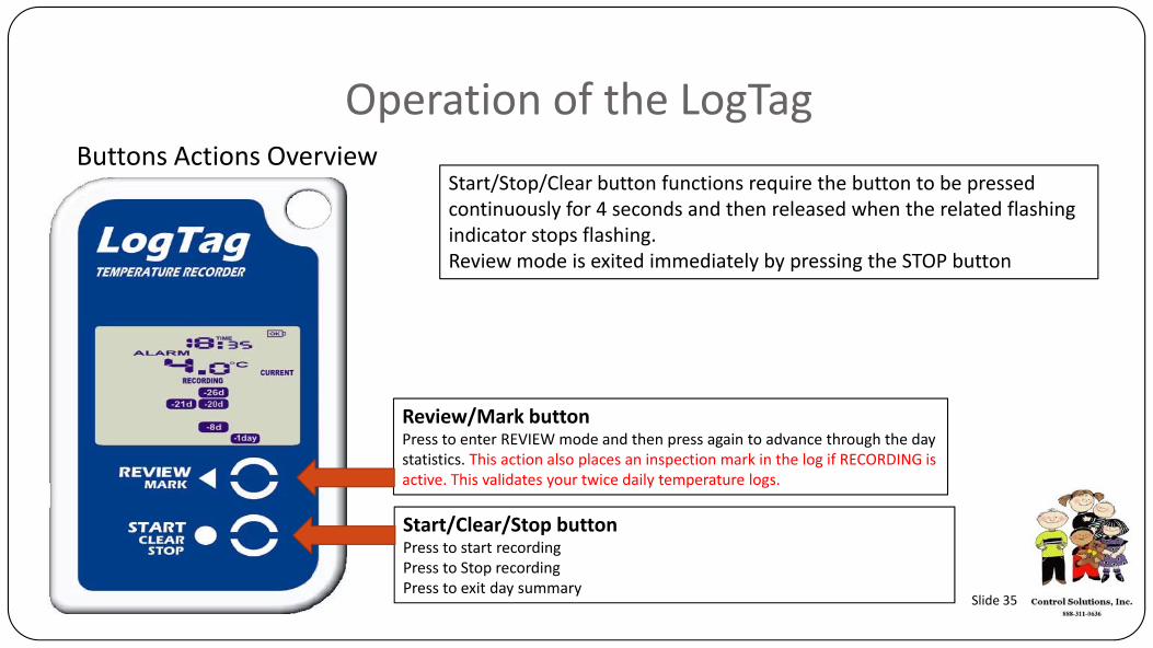
Operation of the LogTagButtons Actions Overview
Review/Mark buttonPress to enter REVIEW mode and then press again to advance through the day statistics. This action also places an inspection mark in the log if RECORDING is active. This validates your twice daily temperature logs.
Start/Clear/Stop buttonPress to start recordingPress to Stop recordingPress to exit day summary
Start/Stop/Clear button functions require the button to be pressed continuously for 4 seconds and then released when the related flashing indicator stops flashing. Review mode is exited immediately by pressing the STOP button
Slide 35
Operation of the LogTag
Starting The Logger
Before starting the LogTagTRED30 go to the Fridge or Freezer, insert the logger into your wall mounting bracket and plug the cable into the data logger
Slide 36

Operation of the LogTagStarting The Logger
The recorder must be in Ready mode for it to be started. In Ready mode the recorder displays the time, battery status and the READY icon.
Press and hold the Start button and observe that the STARTING icon starts flashing.
The button needs to be held down until the flashing stops (normally 4‐6 seconds however can be longer if the button is not continuously depressed)
Release the Start button when the STARTING icon stops flashing
Recorder in READY mode
Slide 37
Operation of the LogTagStarting The Logger
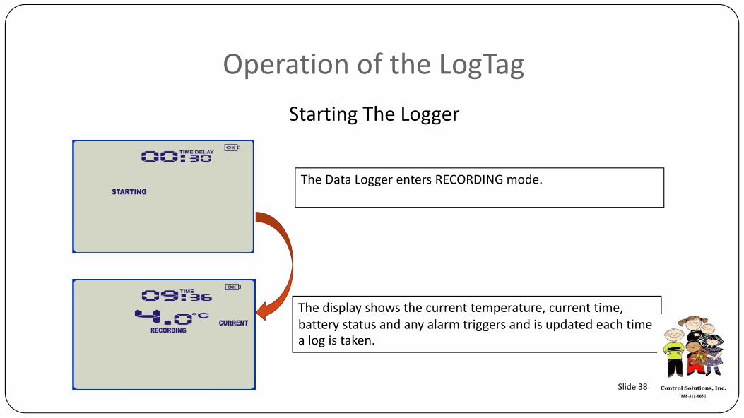
The Data Logger enters RECORDING mode.
The display shows the current temperature, current time, battery status and any alarm triggers and is updated each time a log is taken.
Slide 38
Operation of the LogTagRecording Display
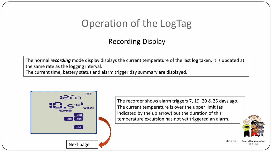
The normal recordingmode display displays the current temperature of the last log taken. It is updated at the same rate as the logging interval. The current time, battery status and alarm trigger day summary are displayed.
The recorder shows alarm triggers 7, 19, 20 & 25 days ago. The current temperature is over the upper limit (as indicated by the up arrow) but the duration of this temperature excursion has not yet triggered an alarm.
Next pageSlide 39
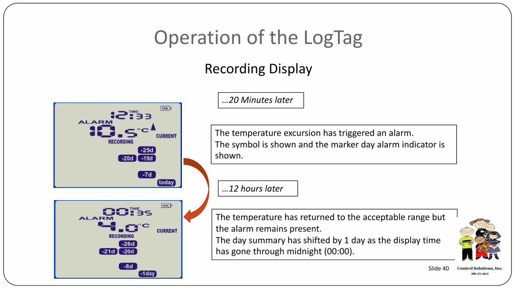
Operation of the LogTagRecording Display
…20 Minutes later
The temperature excursion has triggered an alarm. The symbol is shown and the marker day alarm indicator is shown.
…12 hours later
The temperature has returned to the acceptable range but the alarm remains present. The day summary has shifted by 1 day as the display time has gone through midnight (00:00).
Slide 40
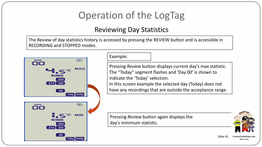
Operation of the LogTagReviewing Day Statistics
Example:
The Review of day statistics history is accessed by pressing the REVIEW button and is accessible in RECORDING and STOPPED modes.
Pressing Review button displays current day’s max statistic. The “Today” segment flashes and ‘Day 00’ is shown to indicate the ‘Today’ selection. In this screen example the selected day (Today) does not have any recordings that are outside the acceptance range.
Pressing Review button again displays the day’s minimum statistic.
Slide 41

Thank you for your business
Control Solutions, Inc.www.vfcdataloggers.com
888-311-0636