LogicPLUS 42S-C LogicPLUS 128S-C - Hit Products Corp · LogicPLUS 42S-C & LogicPLUS 128S-C ......
45
P.O. BOx 929 • 556 S. Mirage Avenue • Lindsay, CA. 93247 For Technical Assistance Call: 800-468-0071 ext. 115 Designed and Manufactured by RainPro ® Lindsay, CA. USA MAde in The USA MAy 15, 2014 LogicPLUS 42S-C & LogicPLUS 128S-C Programming Manual PRO RAIN ® Intelligent Irrigation Solutions TM Two-Wire Irrigation Controller
-
Upload
truongdiep -
Category
Documents
-
view
274 -
download
1
Transcript of LogicPLUS 42S-C LogicPLUS 128S-C - Hit Products Corp · LogicPLUS 42S-C & LogicPLUS 128S-C ......

P.O. BOx 929 • 556 S. Mirage Avenue • Lindsay, CA. 93247For Technical Assistance Call: 800-468-0071 ext. 115
Designed and Manufactured by RainPro® Lindsay, CA. USA
MAde in The USA MAy 15, 2014
LogicPLUS 42S-C & LogicPLUS 128S-C
Programming Manual
PRORAIN ®
Intelligent Irrigation SolutionsTM
Two-Wire Irrigation Controller
Please read the entire operational manual before installing and programming the LogicPLUS-S Controller.
nOTiCe: Before installation, receivers must all be programmed. See pages 27 & 28 for receiver programming instructions.
Features and Specifications ................................................................... 3-6Installation Do’s and Don’ts ....................................................................... 7Installing the LogicPLUS-S ........................................................................ 8Programming the LogicPLUS-S ........................................................... 9-26Receiver Programming ....................................................................... 27-28Diamond Setting ...................................................................................... 29Two Wire Operation ................................................................................. 30Valve Wiring ............................................................................................. 31Wire Connections .................................................................................... 31Trouble Shooting Hints ....................................................................... 32-33Diagram: SPD Board Wiring .................................................................... 34Diagram: Electrical Grounding................................................................. 35Diagram: SPD Ground Wiring ................................................................. 36Diagram: Rain Switch .............................................................................. 37Diagram: Remote Control Technology Interface Wiring .......................... 38Diagram: Multiple Controller Master Valve Wiring ................................... 39Diagram: DBC-BR Wire Connector Installation Instructions.................... 40Diagram: Hand Held Programmer Diagram/Instructions ......................... 41Diagram: Valve Wiring ............................................................................. 42Diagram: LP-SPD-F Wiring ..................................................................... 43Diagram: Master Valve, Pump Start/Fertigation Relay Wiring ................. 44Diagram: Pedestal ................................................................................... 45
Table of ConTenTs

3LogicPLUS-S Two-Wire Controller 3
FEATURES LogicPLUS-S 42 LogicPLUS-S 128Stations Available 1-42 1-128
Programs Available 8 16
Run Time Per Station0-10 hours, 59 min. Max.0-27 hours-use 250% budget
0-10 hours, 59 min. Max.0-27 hours-use 250% budget
Program 6 0-59 min., 59 sec.0-2 hours 30 min.-use 250% budget
0-59 min., 59 sec.0-2 hours 30 min.-use 250% budget
Calendar 0-28 days Max., ODD/EVEN 0-28 days Max., ODD/EVEN
Water Budget 0-250% 0-250%
Rain OFF Days 0-31 days Max. 0-31 days Max.
Pause-Between Stations 0-59 sec. 0-59 sec.
Programs Running Simultaneously 8 8
Maximum Valves Running Simultaneously
8 8
Valves Per Receiver 1 1
Master Valves 3 Master A, B, C 3 Master A, B, C
Rain Sensor Capable Yes Yes
Radio Remote Capable
Yes Yes
Fertigation Options Yes Yes
Table of ConTenTs

LogicPLUS-S Two-Wire Controller44
Field Wire Outputs 4 4Minimum Wire Size 14 gauge 14 gaugeMaximum Wire Run 12,000 Feet 12,000 Feet Maximum Number of Receivers 80 128Receivers Programmable and Re-Programmable
Yes Yes
On Board ReceiverProgrammingCapability
Yes Yes
Remote Receiver Programminguse LP-HHRP
Yes Yes
Security Password Yes Yes
enclosure: Box - Stainless steel, locking, wall or pedestal mount. Pedestal – Stainless steel See diagram page 45 for box and pedestal dimensions.
input Power: 110VAC, 240VAC 50/60Hz Solar 12V DC
Grounding:Enclosure grounded to utility ground. SPD/Output board grounds with 8 foot ground rod. See diagram page 35, 36
Surge/Lightning Protection: Controller Surge Protection is provided by an assembly mounted below the controller panel. This board and its components are like a sophisticated fuse. It will blow in an attempt to save the main circuit board from destruction by line surges mainly created by lightning. It is connected to the main board with a simple cable for easy removal for testing and replacement if necessary.
See diagram page 34
Field Surge Protection is provided by the use of LP-SPD-F devices. Designed to be installed in valve boxes every 200-300 feet and attached to a ground rod. Rod is customer supplied.
See diagram page 43

5LogicPLUS-S Two-Wire Controller 5
Wire type: Single strand direct burial, Jacketed two conduc-tor, or Stranded. No “Special” wire required.
Wire Size: Minimum 14 gauge.Wire Runs: Maximum 12,000 feet for each two wire path
(4 available).Branching & Teeing: Allowed but should be well planned and
minimized.Wire Color: Use of different colored wires is recommended
for ease of wire run identification. Use different colors for each run and every tee or branch.
Wiring Installation: Each individual output, including branches or tees, should be kept separate from the wiring of other outputs.
dO nOT connect the wires of a field output with those of another OR any branch or tee.
dO nOT “Loop” the field wires back to the controller OR back onto themselves.
dO nOT splice and direct bury wire connections/splices. All wire connections/splices should be made in valve boxes.
Maximum Valve Operation: A maximum of 8 valves, any where on the system, may operate simultaneously, of either the same number or combinations of different numbers. The 8 valve maximum plus 3 master valves (A, B, C) plus 1 fertigation valve.Wire Connectors: One of the most critical installation requirements of a LogicPLUS-S two wire system is the quality of your wire connections. If you follow these directions you will have a reliable, depend-able control system for many years. It is suggested to soldier all receiver (red wire) connec-tions to your main two-wire run. Next install the soldiered two-wire connection in a waterproof underground connector housing. When soldering is impractical, a waterproof “dry-type” Hit Products DBC-BR wire connector is required. The above mentioned product will provide an uncontaminated, dry connection. A pair of DBC-BR connectors are included with every LP-RP Receivers for the connection of each Receiver to the two wire path.See diagram page 40
do not use pre-filled wire nut connectors as they will impede the transfer of the signal through the wire splice.

LogicPLUS-S Two-Wire Controller66
Pump Start Relay/Fertigation RelayWhen using a pump start relay, the relay shall be a 24 VAC coil with a maximum inrush of .35 amps and holding .25 amps. The relay will act as a slave to the magnetic relay to control the pump motor. You can use up to a 5hp Hit Products pump start relay attached directly to the relay terminal. See diagram on page 44
Rain SensorThe Rain Sensor terminal is located on the bottom right of the Controller board labeled “RAin OFF.” See Position 11 of the Programming Section of this Manual to Activate this feature.
note: Use only Rain Switches with “Dry Contacts” (No Power) connect the “Normally Closed” contacts. See diagram page 37
Multiple Controller installationInstall a separate ground rod for each controller. Do not connect the field wires of one controller with those of another. Use slave or isolation relays if activating a common master valve. See diagram page 39
Current Monitoring Feature This Feature can be accessed in three dial positions: “Run,” “Semi/Manual/Program Clear” and Test. The displayed number is in milliamps. This is useful when troubleshooting “Short Line,” “Valve Short” or controller operation.
note: When accessed in the “Test” position a reduced power level is sent to the field, which will result in a lower “Current Monitoring Number.”
BoostThis Feature increases power sent to the field over the Two Wire path and is to be used when operating Multiple Valves at extended distance.
Accessory:Hand held programmer. For ProgrammingReceivers away from the controllerSee diagram page 41
Trouble Shooting unit (TSU) for Trouble Shooting both Controller and Receiver/ Wiring issues.
Warranty: Any Receiver returned for warranty must have the DBC-BR connection attached. If the DBC-BR is unattached, warranty is void.
7LogicPLUS-S Two-Wire Controller 7
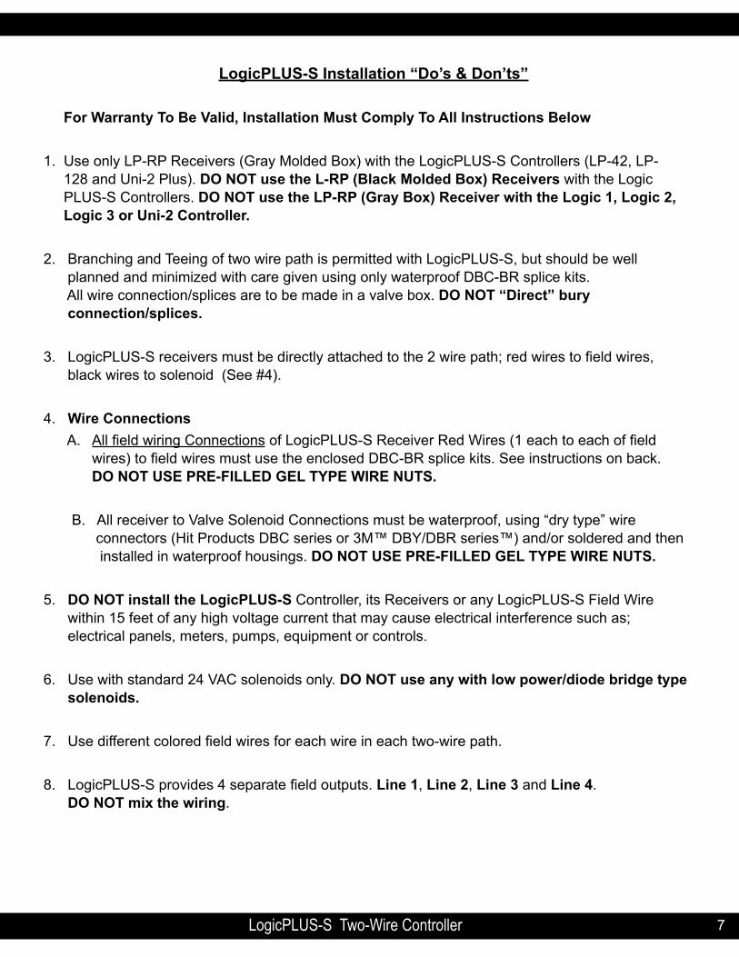
LogicPLUS-S installation “do’s & don’ts”
For Warranty To Be Valid, installation Must Comply To All instructions Below
1. Use only LP-RP Receivers (Gray Molded Box) with the LogicPLUS-S Controllers (LP-42, LP- 128 and Uni-2 Plus). dO nOT use the L-RP (Black Molded Box) Receivers with the Logic PLUS-S Controllers. dO nOT use the LP-RP (Gray Box) Receiver with the Logic 1, Logic 2, Logic 3 or Uni-2 Controller.
2. Branching and Teeing of two wire path is permitted with LogicPLUS-S, but should be well planned and minimized with care given using only waterproof DBC-BR splice kits. All wire connection/splices are to be made in a valve box. dO nOT “direct” bury connection/splices.
3. LogicPLUS-S receivers must be directly attached to the 2 wire path; red wires to field wires, black wires to solenoid (See #4).
4. Wire Connections A. All field wiring Connections of LogicPLUS-S Receiver Red Wires (1 each to each of field wires) to field wires must use the enclosed DBC-BR splice kits. See instructions on back. dO nOT USe PRe-FiLLed GeL TyPe WiRe nUTS.
B. All receiver to Valve Solenoid Connections must be waterproof, using “dry type” wire connectors (Hit Products DBC series or 3M™ DBY/DBR series™) and/or soldered and then installed in waterproof housings. dO nOT USe PRe-FiLLed GeL TyPe WiRe nUTS.
5. dO nOT install the LogicPLUS-S Controller, its Receivers or any LogicPLUS-S Field Wire within 15 feet of any high voltage current that may cause electrical interference such as; electrical panels, meters, pumps, equipment or controls.
6. Use with standard 24 VAC solenoids only. dO nOT use any with low power/diode bridge type solenoids.
7. Use different colored field wires for each wire in each two-wire path.
8. LogicPLUS-S provides 4 separate field outputs. Line 1, Line 2, Line 3 and Line 4. dO nOT mix the wiring.

LogicPLUS-S Two-Wire Controller88
inSTALLinG The LogicPLUS-S
Mounting the controller...........When selecting the controller installation location, make sure control-ler and all related wiring is a minimum of 15 feet from any high voltage control boxes, pumps or any high voltage equipment. This irrigation controller is a computer and should be installed accordingly. When mounting the LogicPLUS-S indoors, notice the “keyhole” shaped mounting slot as well as 2 mounting holes on the back of the controller. Use the template provided to locate mount-ing screw locations. Remove the four face plate screws and two lower panel screws to access enclo-sure mounting screws. To attach to wall studs, use a #10 screw, leaving 1/4” of the shank exposed to slip into the “keyhole” slot. To additionally secure the controller, drive additional screws through the bottom mounting holes into the stud or cross bracing.When mounting the LogicPLUS-S outdoors, use the same procedure as above. When attaching the controller to hollow walls, masonry, or cinder blocks, use appropriate toggle bolts, masonry shields or compression drive bolts. For additional weatherproofing, run a silicon bead around the case be-tween the controller and the wall. It is also recommended to fill mounting holes with silicon as well, to prevent water or insects from entering the controller.The LogicPLUS-S should be hard wired to power supply the by a qualified electrical technician. Use an approved GFi device and utilize proper grounding techniques using the green wire from controller transformer. This will help assure safety as well as performance and reliability of the LogicPLUS-S controller. The manufacturer’s warranty becomes invalid without proper grounding as per local code. See enclosed “installation diagram for Primary Wiring.” Warn-ing! When connecting the field receivers, make sure there is no power to the printed circuit board, controller and/or the receivers; this will prevent the shorting of receivers and controller.Unscrew the LogicPLUS-S bottom terminal plate and route the field wires (one to four sets) through the hole at the bottom of the controller. Secure each 2-wire run under the appropriate terminal on the terminal strip labeled “Line 1,” “Line 2,” “Line 3,” “Line 4.” If using multiple outputs, keep each 2 wire set independent. do not mix output “Line 1” with output “Line 2,” “Line 3” with “Line 4” or any other combination. It is strongly suggested to use different colored wires for each wire used. See diagram page 34
TeST BeFORe BACK-FiLLinG TRenCh
To easily test for communication and wire integrity, connect each receiver to the field wiring at each planned location. It is not necessary for receiver to be attached to solenoid/valve for test, but O.K. if already connected. Do not allow black receiver wires to touch each other (short or ground) when test-ing. Manually sequence controller through each station number for minimum of 30 seconds, checking each activated receiver in the field for a continuously activated bright LED light on each receiver. A continuously activated bright LED light on receiver during station activation confirms satisfactory com-munication.
Please read the entire operational manual before installing and programming the LogicPLUS-S Controller.

9LogicPLUS-S Two-Wire Controller 9
PROGRAMMinG The LogicPLUS-S 42 and LogicPLUS-S 128 COnTROLLeRS
The LogicPLUS-S Controllers are so easy to program because the four sets of black up/down arrow buttons correspond to whatever is directly above them in the display. You can toggle between ON and OFF, set hours, minutes, and seconds, or even select program numbers, valve numbers, and start times simply by using these up/down buttons located directly under their functions. The square Function button located to the right of the arrow buttons will access the functions listed when the dial is turned to the numbered position stated by each function.
The controller programming consists of 8 buttons to control the display, a twelve position rotary switch and a special function key for more special options. The 8 buttons that control the display are located directly below the portion of the display they control. Each set (two buttons) of buttons operates the display up or down for ease of getting to the function, number, valve or time desired. For ease of ex-planation, the following terminology will be used throughout these instructions. The set of buttons to the far left will be button set 1, directly right of these will be set, directly right of set 2 will be set 3 and the last set or far right set will be set 4, the special Function button in the upper right of the control panel, will be referred to as set 5.
nOTe: See diagram page 9-26
The main rotary dial has 12 positions just like the numbered hour positions on a clock 1-12. The rotary switch consists of the following positions and functions:
nOTe:When you first install your LogicPLUS-S 42 or LogicPLUS-S 128 controller, use the Master Clear feature to clear all possible information stored in the unit. Put dial in position 10, press top right Up/down key set 4 under “CLR” OFF. display will change, then press top right Up/down key set 4 under “Master yes” again. Controller will automatically clear ALL program-mable data except current date and time.

LogicPLUS-S Two-Wire Controller1010
PROGRAMMinG COnTROLLeR
SET 1 SET 2 SET 3 SET 4 SET 5
11LogicPLUS-S Two-Wire Controller 11
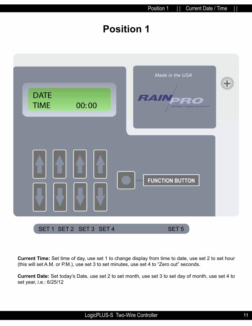
Current Time: Set time of day, use set 1 to change display from time to date, use set 2 to set hour (this will set A.M. or P.M.), use set 3 to set minutes, use set 4 to “Zero out” seconds.
Current date: Set today’s Date, use set 2 to set month, use set 3 to set day of month, use set 4 to set year, i.e.: 6/25/12
Position 1 | | Current Date / Time | |
Position 1
SET 1 SET 2 SET 3 SET 4 SET 5

LogicPLUS-S Two-Wire Controller1212
Position 2 | | Valve Run Times | | Function Button-Pre Wet Function Button-Fertigation
Set Valve Run Times: Use set 1 to choose the program, use set 2 to choose the valve number, use set 3 to set hours, use set 4 to set minutes. Input the total irrigation run time desired for each valve, including pre wet and fertiga-tion time.
Pre Wet and Fertigation option: Press Function Button, the display will now be the same, except with the following changes, a “P” will show in front of Hours. Use set 3 or 4 to set amount of hours and minutes for the pre-wet time. Press Function Button, again the display will stay the same except for a “F” that will show in front of hours, use sets 3 or 4 to set the amount of hours and minutes for fertigation.
definitions: Pre-Wet will run concurrently at the start of the valve run time.
Position 2

13LogicPLUS-S Two-Wire Controller 13
Fertigation will start at the conclusion of the programmed Pre-wet cycle and will automatically ac-tivate the fertigation receiver. If only fertigation time is programmed and no pre-wet time is pro-grammed, fertigation will start at the commencement of the valve run time programmed. This receiv-er will remain activated for as long as the fertigation is programmed. If the total valve run time is 15 minutes, pre wet for 3 minutes and fertigation for 5 minutes, then there will be 7 minutes remaining of valve run time after the fertigation cycle ends.
nOTe: At no time will the controller permit the total time of pre-wet and fertigation to exceed the total run time programmed. no pre-wet run times need to be programmed in order to run the fertigation mode.
nOTe: Program 6 can only be set in minutes and seconds, as all other programs can be set in hours and minutes. The maximum run times can be set from 1 minute to 10 hours and 59 minutes on all programs except 6, which can be set for a minimum of 10 seconds to a maxi-mum of 59 minutes and 59 seconds. With the water budget feature (position 8) these run times can be increased or decreased from 0% to 250% in 5% increments.
nOTe: A maximum of any 8 receivers/valves (any combination) may be operated simultaneously.
Position 2 | | Valve Run Times | |
Position 2

LogicPLUS-S Two-Wire Controller1414
Position 3 | | Pause | |
Pause: Use set 1 to choose the program, use set 2 or 3 to set desired pause time, use set 4 to turn master valve or pump start function ON or OFF during pause function.
definitions:
Pause: Amount of time delay between sequential valve openings in a program.
Master: Master ON will keep the master valve or pump relay ON during pause.
Master OFF: Will turn master valve or pump relay OFF during pause.
note: in order for the master valve to function, the master valve must be activated (See position 8 page 21) for that specific program.
Position 3

15LogicPLUS-S Two-Wire Controller 15
Position 4 | | Start Time | |
To set start times, use set 1 to choose the desired program, use set 2 to choose the start number, always use start 1 for the first start time after midnight and so on through start 8 (LogicPLUS-S 42) start 16 (LogicPLUS-S 128) use set 3 to set the hour of the start time, use set 4 to set the minutes of the start time.
note: The start time is part of the first leg of a pre-programmed function called “diamond Settings” Refer to diamond settings at the end of this programming guide for full details.
Position 4

LogicPLUS-S Two-Wire Controller1616
Position 5 | | Total Run Times | |
To review the total run time in a specific program, use set 1 to choose the program number. The total run time of that specific program is shown in the lower right hand position of the display. You can review the water budget setting along with the total run time in this position. If the water budget is changed from the default 100% the total run times will change in this position, but in position 2, the valve run times will stay inputted. The actual running valve is determined by the input in position 2 multiplied by the water budget setting in position 8.
note: On a 7 day calendar the actual day will be displayed.
note: By adjusting the budget up or down (0% to 250%) it will change the total run time. See position 8 for further discussion. The budget is the second leg of the diamond Setting.
Position 5

17LogicPLUS-S Two-Wire Controller 17
Position 6 | | Calendar | | Function Button Odd-Even
The calendar is the third leg of the diamond Setting. After programming the run times and the start times, the calendar will automatically establish the minimum calendar period. You can manually change the calendar to any desired period, longer than the minimum “Auto-calendar” period, but not shorter. By pressing set 1 to select the program, press set 2 to change the number of days desired in the calendar, (if the total run time exceeds one day, the calendar can not be set backwards.) Press set 3 to review the days of the calendar. By pressing set 3 repetitively, the display above set 4 will show one of the fol-lowing events: STRT (start), RUN or OFF for each day of the calendar.
To review the numbered day of the calendar the controller is currently on, use set 1 to choose the pro-gram desired. The day of the calendar will be displayed directly right of the word “DAY” in the upper display. You can change the day of the calendar by using set 3 buttons. This will or can bring all days of all programs to the same day for calendar purposes.
Position 6

LogicPLUS-S Two-Wire Controller1818
Position 6 | | Calendar | | Function Button Odd-Even
note: The calendar automatically resets all programs to day 1, today, when “Master Clear” is activated. The calendar automatically resets to today, day 1, when any value in “Calendar” is changed. The calendar can be manually changed to any day including today in Position 5, “Total Run Time.” day value has to be equal to or less than “calendar” number of days. except when using a Seven day Calendar, display will show day of the week. (example) SUn., MOn., Wed., and so on.
1. Odd / even: May be accessed by pressing Function Key Set 5.2. Use Set 1 to select program use Set 3 and 4 to On or OFF. 3. note: To exit the Odd / even feature both Odd and even must be set to OFF. Press the function button to exit.4. note: Runtimes must not go beyond 11:59 pm.
definitions: Start: This is the day of the calendar that the program will start. This will be automatically set upon initial programming or set by the user. This is day 1 of the calendar, the day you set up the calendar or programmed the program or let the auto-calendar set up the calendar.
Run: The total run time of the program has carried over into the second or more days and the program will be running these days to complete.
Off: The user has programmed in additional days that the program will not be active.
note: The number of days that the calendar automatically sets up is determined as follows: The number of hours from 12:00 midnight to the first start time plus the total run time, di-vided by 24 hours will equal the number of calendar days.
For calculating the calendar for “Run” Times over 24 hours. This example is for 56 hours Run Time per Program.example: If a start time is 8:00 am, then the first calculation would be 8 hours plus a total run time of 56 hours for a grand total of 64 hours, divided by 24 hours would equal a 2.67 day calendar, the display would show a 3 day calendar, as follows, day 1 STRT, day 2 RUN and day 3 RUN. If you wanted to irrigate every 4th day, use set 2 to expand the calendar from 3 days to 4 days, day 4 would show OFF.
note: in cases not using a 7 day calendar and the information in the calendar is changed, the “day” in the “Total Run Time” position will reset to “day”.
note: To further understand the diamond setting for calendar, read the diamond setting on page 29.

19LogicPLUS-S Two-Wire Controller 19
Position 7 | | Looping Program No. 6 | | Function Button- Security Password
Any valve run times and start times set in program 6 can be looped if desired. There must be individual run times for each desired valve and ONE start time in program 6 for looping to be activated. Use set 3 and set 4 to establish the total amount of loop time desired. Use set 2 to turn looping feature ON or OFF.
hints for using Looping: Looping will run a program continuously for the amount of time set in posi-tion 7 looping. For example: If looping is set for 6 hours and the start time is 8:00 am, program 6 will start at 8:00 am and run for 6 hours. A new lawn can be irrigated for 5 minutes every hour by doing the following. Valves 1, 2 and 3 operate the new lawn, set run times for 5 minutes each on valves 1, 2 and 3, then go to a valve that is not being used and set run time for 45 minutes. You want to irrigate from 10 am until 5 pm. Set start time for program 6 at 10:00 am and go to position 7, set loop for 7 hours and turn looping ON. The program will start at 10 am and run valve 1 for 5 minutes, then valve 2 for 5 minutes and then valve 3 for 5 minutes and then the valve that is not being used for 45 minutes and then back to valve 1 and so on until 7 hours runs out, which will be 5:00 pm.
Caution! if operating with a pump, the 45 minutes will cause “dead heading” on the pump and may damage the pump or pipelines.
Position 7

LogicPLUS-S Two-Wire Controller2020
note: Program 6 can be sensor activated, such as a temperature sensor. The terminals for remote operation are located on the terminal board and marked pr6trg (program 6 trig-ger). Program the amount of run times per valve in program 6, do not put in a start time, make sure the program is On in position 8 and whether or not the master should run with program 6.
Program the amount of loop time in position 7. When the remote sensor activates and closes the contacts for more than 30 seconds, program 6 will operate for the looping time programmed.
If for any reason the remote sensor contact opens during the looping cycle, the looping cycle will continue until the programmed time is completed. The sensor must open and close the contacts to operate the looping cycle a second time. If, for any reason, the contacts open and close dur-ing the pre-programmed length of looping, the looping program will reset at that time and start over again.
Position 7 | | Looping Program No. 6 | | Function Button- Security Password Position 8 | | Program / Master Valves ON/OFF | | Pump Start | | Water Budget 0%-250%

21LogicPLUS-S Two-Wire Controller 21
Position 8 | | Program / Master Valves ON/OFF | | Pump Start | | Water Budget 0%-250%
Use set 1 to choose the program desired, use set 2 to turn a program ON or OFF (a fully pro-grammed program can be disabled by this function) use set 3 to turn Master Valve A, B or C ON or OFF, use set 4 to increase or decrease the budget feature of the program 0%-250%. The amount of time in position 2 will not change in the display but the actual time will be increased or decreased by the amount of budget %. The new “water budgeted” run times can be viewed in position 5. Use Set 5 (Function Button) to boost power on Master or individual Valves. To be used in long run, multiple valve operation.
Position 8
note: Master Valves, pump start and Fertigation relays now Run OFF the same two wire path as the valves using a properly programmed LP-RP Receiver.

LogicPLUS-S Two-Wire Controller2222
Position 9 | | Test Cycle | | Function Button - Short Test
Use set 1 to set run times in minutes, use set 2 to set run time of seconds for test cycle, set 3 has no response, and use set 4 to select valve range to test, display will change, use set 1 or set 2 to select valve range start and end, use set 3 to select Master A, B or C if required, use set 4 to start test cycle, press set 4 again to stop test cycle.
The controller will immediately run each valve in sequence for valve range and predetermined run time for visual review of the system operation.
note: The pause setting in position 3 for program 1 will determined the amount of pause between stations during the test cycle operation.
Use set 5 Function Button to perform a short test.
Short Test This feature to be used for troubleshooting. See page 32.
Position 10 | | Semi / Manual / Program / Master Clear | | Current Monitoring Special Function
Position 9

23LogicPLUS-S Two-Wire Controller 23
Position 10 | | Semi / Manual / Program / Master Clear | | Current Monitoring Special Function
Semi- use set 1 to choose the program you want to activate for one cycle, use set 2 to activate that program ON. Leave the dial in number 10 position. [Rotating the dial will cancel the program.] Set 5 will activate the Current Monitoring feature.
note: 30 minutes after the conclusion of the selected program the controller will automati-cally revert to the “RUn” condition, without putting the dial back to “Run.”Manual — Press set 3 to activate manual mode the display will change, use set 1 to choose the specific valve number to be operated manually for a predetermined time, use set 2 to set amount of hours to run, use set 3 to set amount of minutes, use set 4 to tell the controller whether or not you want the master valve A, B, C, and pump on during this manual operation. Valve will immediately be activated for that period of time. Use set 5 to activate the Current Monitoring feature. Leave the dial in number 10 position. [Rotating the dial will cancel the program.] At the conclusion, the controller will go back to “RUN” mode without turning the Dial back to the “RUN” position. You can activate up to 8 valves at the same time in manual mode.
note: 30 minutes after the conclusion of the selected valves the controller will automatically revert to the “RUn” condition.
Position 10

LogicPLUS-S Two-Wire Controller2424
Program Clear: Turn rotary switch to position 10. Use set 4 to choose program clear, the display will change, use set 1 to choose the program that you desire to clear all the information from, use set 2 to answer yes. Set 3 can be used to exit prior to clearing program.
note: By clearing the program all information for that program is deleted.
Master Clear: will clear all the information in the controller by way of the following: Turn rotary switch to position 10, press set 4, display will change, and then press set 4 again.
note: All information data in all programs will be deleted. Only the current time and date will remain.
note: Set 3 can be used to exit prior to performing a Master Clear.
note: Semi/Manual mode can be operated when controller is in “OFF” mode.
Position 10 | | Semi / Manual / Program / Master Clear | | Current Monitoring Position Current Monitor-

25LogicPLUS-S Two-Wire Controller 25
Position 11 | | Rain Delay Sensors / Sensor Auto / ON / OFF | |
days of delay: Use Set 1 to select the number of days to delay watering (the controller will not run for the number of days set). The new day starts at midnight.
Auto: Use set 4 to turn ON or OFF the Automatic watering schedule. Use this setting when pro-gramming receivers or when no watering is required for extended periods of time. The Semi and Manual Functions in Dial position 10 can still be used.
Rain: Use 3 to change to ON when a Rain Sensor is connected OFF when no Rain Sensor is connected or to override a connected Rain Sensor.
Position 11

LogicPLUS-S Two-Wire Controller2626
Position 12 | | Run Program Receivers | | Current Monitoring Features
In the “Run” position the controller will execute all that it has been instructed to do. Adding new or changing existing information can be done at anytime, even with a program running. As soon as the dial is rotated and new instructions are input, the controller will interrupt any on going activity and accept the new instructions. When the dial is returned to the “Run” position scheduled activity will resume.
Use of the Function Button while a program is running will access current monitoring. Use of the Func-tion Button with no program running will access receiver programming.
See “LogicPLUS-S Receiver Programming instruction.”
Position 12

27LogicPLUS-S Two-Wire Controller 27
1. Set the controller in the OFF position. Turn the rotary switch to position 11 (Rain Off/Auto On/Off) use the top right arrow key set 4 to turn the setting from ON to OFF. This will stop any program that is running and prevent any form starting while programming receivers.
2. disconnect the field wires.
3. Set the Rotary switch to the “Run” position. Position 12.
4. Press the “Function” key to access the “Set Decoder ID” screen.
5. Connect the 3.5mm plug wire to the 3.5mm Jack Connector on bottom of board. (Programming Port)
6. Connect each of the red wire on receiver with each of the alligator clips.
7. Be sure black receiver wires are not touching.
8. Using the arrow keys corresponding directly underneath the ID number in the display (set 3) select the desired number or MSTRA, MSTRB, MSTRC or Fert, for a Master or Fertigation receiver. The Master and Fertigation choices are found by scrolling through the station number. Use the down arrow key to quickly access the Master and Fert settings.
9. Press the arrow key corresponding to “Enter” on the display (right up set 4).
10. The LED on the receiver will flash three (3) times.
11. Remove the red leads.
12. Install “Receiver Number Identification Tag” (see below listed instructions.) If programming more receivers repeat from step 5. (see “Receiver Programming Leads” below.)
13. To end programming press “Function” key to return to “Run.” Controller will not resume “Run” automatically.
14. Re-connect field wires.
15. Set the Controller back to On to resume Auto Programming. Rotate the dial to position 11. Use the top right arrow key to turn the setting from OFF to ON.
Position 12 LogicPLUS-S Receiver Programming instructions
When programming a receiver with a controller that is installed with the field wires connected:

LogicPLUS-S Two-Wire Controller2828
Programmable Receiver number identification Tags
Hit Products has developed a user friendly, flexible means to identify the number of the field pro-grammed receivers during the receiver programming process. Inside every box of programmable receivers, you will find one set of identification tags numbered 1-128. You will use these receiver identification tags as follows:
1. Every time a receiver is programmed, find the corresponding numbered identification tag and immediately attach to receiver.
2. To attach identification tag to receiver, insert one red receiver wire into the hole (from front to back) to the left of the appropriate numbered tag as you are looking at the number. Pull red wire all the way through the hole until identification tag is approximately one inch from body of receiver.
note: This will leave the engraved number unobstructed by the wire.
3. Insert same end of same red wire back through hole (from back of tag towards front) and continue to pull wire through until tight. The number on the tag should now be readily visible and the red wire positioned on back (blank side of tag). See above.
4. Should receiver ever be reprogrammed to a different number, make sure to replace the identification tag with the appropriately numbered identification tag. Failure to do so can create extreme confusion!
1RED
RED
BLACK
BLACK
LED
RECEIV-
29LogicPLUS-S Two-Wire Controller 29
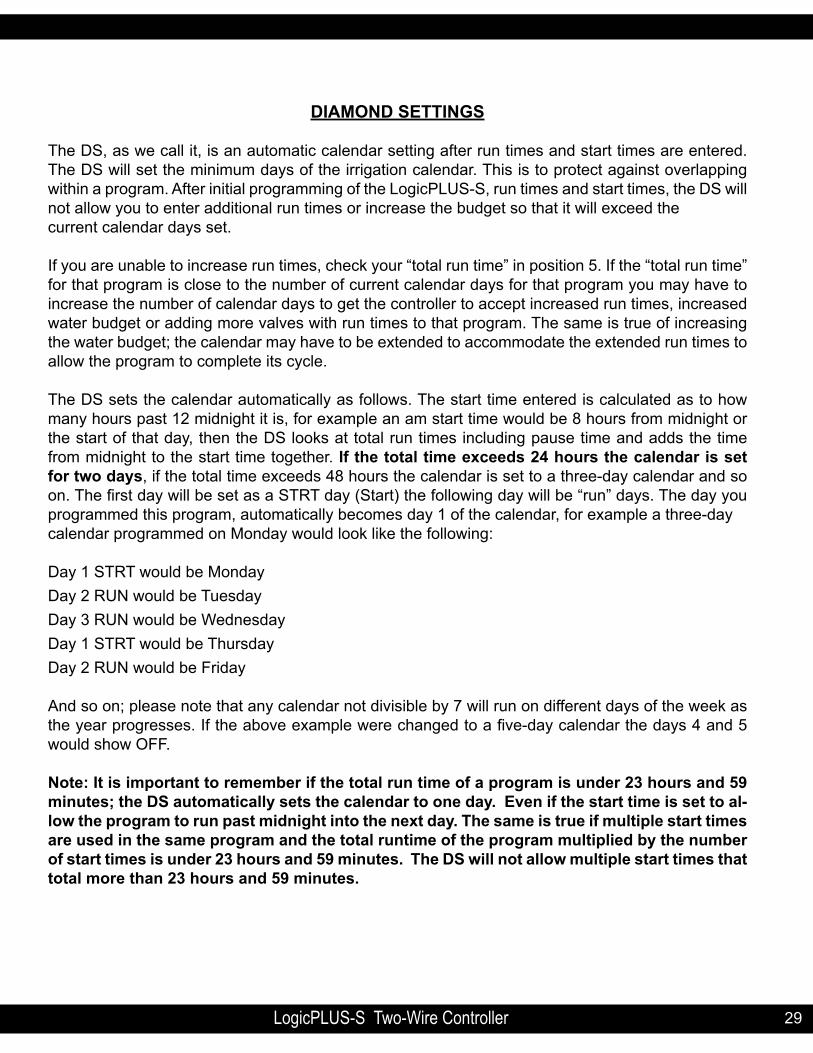
diAMOnd SeTTinGS
The DS, as we call it, is an automatic calendar setting after run times and start times are entered. The DS will set the minimum days of the irrigation calendar. This is to protect against overlapping within a program. After initial programming of the LogicPLUS-S, run times and start times, the DS will not allow you to enter additional run times or increase the budget so that it will exceed the current calendar days set.
If you are unable to increase run times, check your “total run time” in position 5. If the “total run time” for that program is close to the number of current calendar days for that program you may have to increase the number of calendar days to get the controller to accept increased run times, increased water budget or adding more valves with run times to that program. The same is true of increasing the water budget; the calendar may have to be extended to accommodate the extended run times to allow the program to complete its cycle.
The DS sets the calendar automatically as follows. The start time entered is calculated as to how many hours past 12 midnight it is, for example an am start time would be 8 hours from midnight or the start of that day, then the DS looks at total run times including pause time and adds the time from midnight to the start time together. if the total time exceeds 24 hours the calendar is set for two days, if the total time exceeds 48 hours the calendar is set to a three-day calendar and so on. The first day will be set as a STRT day (Start) the following day will be “run” days. The day you programmed this program, automatically becomes day 1 of the calendar, for example a three-day calendar programmed on Monday would look like the following:
Day 1 STRT would be MondayDay 2 RUN would be TuesdayDay 3 RUN would be WednesdayDay 1 STRT would be ThursdayDay 2 RUN would be Friday
And so on; please note that any calendar not divisible by 7 will run on different days of the week as the year progresses. If the above example were changed to a five-day calendar the days 4 and 5 would show OFF.
note: it is important to remember if the total run time of a program is under 23 hours and 59 minutes; the dS automatically sets the calendar to one day. even if the start time is set to al-low the program to run past midnight into the next day. The same is true if multiple start times are used in the same program and the total runtime of the program multiplied by the number of start times is under 23 hours and 59 minutes. The dS will not allow multiple start times that total more than 23 hours and 59 minutes.

LogicPLUS-S Two-Wire Controller3030
Two Wire Operation
Controller OperationWhen the controller is activated by either “Auto” programming or a “Manual” Input, the power plus an encoded signal is supplied to the four field Outputs.
Receiver OperationsThe Receiver operates as an electronically controlled switch. When the receiver recognizes the en-coded signal that matches its programmed data, it then allows or “switches” power to the solenoid at the valve. Each receiver has a Red LED that will light when the receiver is “switched” or activated. When testing or troubleshooting, this LED is a convenient indicator of the Receiver Status. Lit condition indi-cates that the signal and power are present and the Power is being sent to the solenoid.An unlit condition indicates the receiver is not activated. This is an indication that the power and/or signal is not present.
Line Short/Valve Short CodesThe controller, through its current monitoring ability, can display two fault conditions: One being “Short Line” the second being “Valve Short.” These faults are triggered when current draw has exceeded a present level.
note: no Output is sent to the field during these conditions. If this current draw is sensed at a programs initial start a line short will be displayed. If the current draw is sensed during a valve run time then short valve with a valve number will be dis-played.
Short line will retry after 20 minutes. Turning the dial out of “Run” and back will clear the display. The controller will then try to continue any scheduled program. If the short has not been corrected the con-troller will go back into “Line Short”.
“Short Valve” will stay displayed during the valve run time. The controller will monitor the program status and operation will resume when the next valve is activated. If the problem has not been corrected by the time the controller is scheduled to Run again the “Short Valve” will repeat.
note: These codes are designed to protect the controller and transformer. in extremely long wire runs the current level may not be reached to activate “Short” due to line loss.

31LogicPLUS-S Two-Wire Controller 31
VALVe WiRinGThe field wiring from the controller to the receivers consists of either one, two, three or four, 2-wire runs, which connect, in series, to each valve location. Each 2-wire run is totally independent of the other relative to wire size requirements and the number of valves operating simultaneously. All four 2-wire runs receive and output the exact same information. The purpose of four independent 2 wire runs are for reducing the potential amount of “back tracking” when valves are located in more than one general direction from the controller. Theoretically, with the Logic controller located in the center of an irrigation project, one 2-wire run would go one direction and the second, third and fourth could go in other direc-tions. Each 2-wire run starts at the controller and ends at the last receiver/valve for that wire run.
1) do not loop the field wires back to the controller. 2) do not connect field wires of one 2-wire run with those of another. each run is independent.3) do not connect the field wires of one controller with those of another controller.
For the main 2-wire runs, it is very important to size the wire properly. Consideration for designing the proper wire size includes the total wire distance from controller to the farthest receiver and how many valves will be operating simultaneously. Wire size must be designed using Ohm’s law for any applica-tion.
The field wiring should consist of one to four continuous main 2 wire runs starting at the controller ter-minal labeled “Line 1,” “Line 2,” “Line 3,” “Line 4” and continuing to the last receiver/valve of that wire run. If using the multiple output feature, use one continuous length of wire independently for each output. Every receiver is to be connected directly anywhere on one of your main two-wire continuous runs. The last receiver installed is the end of the main two wire run. You may operate a maximum of eight of the same numbered receivers eight valves maximum of any random numbered receivers at any one time.
WiRe COnneCTiOnS: One of the most critical installation requirements of a Two Wire system is the quality of your wire con-nections. If you follow these directions you will have a reliable, dependable control system for many years. It is suggested to solder all receiver (red wire) connections to your main two-wire run. Next in-stall the soldered two-wire connection in a waterproof underground connector housing. When soldering is impractical, a waterproof “dry-type” connection such as the Hit Products DBC-BR wire connector is required. The above mentioned products will provide an uncontaminated, dry connection. See diagram page 40
do not use pre-filled wire nut connectors as they will impede the transfer of the signal through the wire splice.

LogicPLUS-S Two-Wire Controller3232
TROUBLeShOOTinG hinTS FOR LogicPLUS-S TWO WiRe SySTeMSPROBLEM SOLUTIONSDisplay Blank.
No Power.
Incorrect Programming Controller is OFFProgram is OFFNo start timesCalendar not set correctlyWater budget set at zero.
1) Check: 110v or 220v supply and corrections. Correct as needed.
2) Check: 12V DC at the controller board terminals. If no 12V DC possible bad power supply.
3) Check: the connector between the SPD board and controller. Re-seat if needed.
Controller Operates in “Manual” or “Test” but not in “Auto.
Incorrect Programming Controller is OFFProgram is OFFNo start timesCalendar not set correctlyWater budget set at zero.
Correct Programming
See the Programming section of this Manual.
Controller Displaying “Short Line” or Turning ON/OFF and “Clicking”.
High Current Draw1) More than 8 valves activating.
2) Short field wires.
3) Field wires of one controller connected to field wires of a second controller.
1) Possible failed Receiver.
2) Field wires shorted.
3) Possible failed LP-SPD-F.
No Valves Activating. 1) Controller not activating.
2) Field Wire Connection.
1) See “Controller Operates in Manual and Test but not Auto”.
2) Check the “Field Out” wire connections at the Controller.
3) Failed Controller or SPD BO Replace Panel or SPD BO.
Single Valve not Activating. 1) Bad wire connection.
2) Failed Receiver.
1) Check Receiver Wire Connection.
2) See Receiver Operation.Multiple Valves not Activating. 1) Field wiring or connections. 1) Check wiring and
connections between the last valve working and the first valve not working.

33LogicPLUS-S Two-Wire Controller 33
PROBLEM SOLUTIONSDisplay is flashing “Rain Off”. Power is being supplied to Rain
Off connector.Incorrect Rain Switch.
Controller displaying reads “Valve Short” with a valve number.
High current draw during valve run time.
1) Possible bad solenoid.
2) Shorted wires between receiver and solenoid.
3) Possible bad receiver.Display frozen, does not respond to rotating valve.
Micro is locked. 1) Turn power off for a minute, then back on.
2) Perform a Master Clear.*
note: *All Controller information Will be lost.
Display reads ‘SPD Board Not Attached”.
Controller does not sense SPD board.
1) Interface cable not connected
2) Bad Connector/Cable, reset connectors
Valves Turning ON/OFF during run time.
Possible EMF interference Check: Controller, Receivers and Field Wiring location in respect to any high voltage.

LogicPLUS-S Two-Wire Controller3434
LogicPLUS-S Panel/SPd Board Wiring

35LogicPLUS-S Two-Wire Controller 35
electrical/Ground for 110-240VAC 50/60hz Application
110-240VAC50/60 Hz
12VDCPOWER SUPPLY

LogicPLUS-S Two-Wire Controller3636
Ground Wiring
nOTe:Use separate Ground Rod for each Controller in multipleController installations.
nOTe:SPD Ground to a Grounding RoddO nOT COnneCT TO UTiLiTy GROUnd.

37LogicPLUS-S Two-Wire Controller 37
Rain Switch Connections
Normally ClosedContact Wire
NOTE: Dry Contact DO NOT APPLY POWER
MINI CLICK TYPE
COMMON WIRE
RAIN SWITCH CONNECTIONS
After the Rain switch connections are completeturn the dial to position 11 use set 3 arrow tochange the display from Rain/Off to Rain/OnNote: This step must be performed to acknowledge a Rain Sensor.
Note: Turning the display from Rain/On to Rain/Offmay be used to override the Rain Sensor.See Dial Position 11 in the Programming Instructions.
LOGIC PLUS - S RAIN OFF SWITCH CONNECTION DIAGRAMLogicPlus-S RAin OFF SWiTCh COnneCTiOn diAGRAM
Note: Dry ContactdO nOT APPLy POWeR
Normally ClosedContact Wire
MINI CLICK TYPE
COMMONWIRE

LogicPLUS-S Two-Wire Controller3838
LogicPLUS-S Wiring diagram For Remote Control Technology interface
ADDRESS SWITCHESANTENNA JACK
Locking Tabs UP
R.F. INTERFACE
WIRING INSTRUCTIONS
1. Turn off Power.2. Remove the Logic face plate and stainless steel panel3. Mount the antenna bracket utlizing the holes in the Logic stainless steel cab ( upper right hand side or top ). See Remote Technology’s antenna mounting directions.4. Connect antenna leads.5. Using the double backed tape, mount the receiver card directly to the stainless steel cab. Locate properly to leave access to the address switches .6. Connect antenna lead to ATENNA JACK.7. Connect R.F. Interface Cable. Observe Polarity Locking Tabs - Up Positions. 8. Reinstall front panel.9. Apply Power.
LOGIC PLUS-S WIRING DIAGRAM FOR REMOTE CONTROL TECHNOLOGY INTERFACE
Locking Tabs UPR.F. INTERFACE

39LogicPLUS-S Two-Wire Controller 39
Co
ntro
ller AC
on
troller B
Co
ntro
ller C
Field W
ire
To o
ther Valves
Master Valve
Receiver
Isolatio
n Relay
CO
MN
OC
OM
NO
CO
MN
OIso
lation
RelayIso
lation
Relay
Master Valve
ReceiverM
aster ValveReceiver
24 VAC
MA
STER VALV
E
LOG
IC PLU
S-S MU
LTIPLE CO
NTRO
LLER MA
STER VALE W
IRING
To o
ther Valves
To o
ther
Valves
Red
Red
Red
Red
Red
Red
Blk
Blk
Blk
Blk
Blk
Blk
LogicPLUS-S Multiple Controller Master Valve Wiring

LogicPLUS-S Two-Wire Controller4040
dBC-BR Wire Connector installation instruction
1
2
3
45
WARNING! Turn off power before installing or removing connector.All electrical work should be done according to appropriate electrical codes.
IMPORTANT NOTICE: Before utilizing the product, the user shoulddetermine the suitability of the product for its intended use. HitProducts Corp. expressly disclaims the implied warranties and conditions of merchantability and fitness for a particular purpose.In no case shall Hit Products Corp. be liable under any legaltheory, including but not limited to contact or strict liability, forany direct, indirect, special, incidental or consequential damagesresulting from product use.
Manufactured by Hit Products Corp., Lindsay, Ca, USA www.hitproductscorp.com
mtd-0012
DBC-BR Wire Connector Installation Instructions
Insert Brass Connector with Screw showing in the opening in Handle.Insert all Wires into Brass Connector.
Use Screwdriver to tighten Screw very firmly on Wires while holding splice in Handle. Pull Wires to check for integrity of connection.Repeat process if any loose Wires.
Remove Wires and Brass Connector form Handle.
Insert Wires to bottomof Tube.
Bend Wires to fit underCap and securely snapCap to fully closedposition.
5/8"

41LogicPLUS-S Two-Wire Controller 41
SCREW
SCREW
SCREW
SCREW
LogicPLUS Two Wire
Hand Held Programmer
LogicPLUSFor LogicPLUS Receivers Only
Set / #
Test / #
ON / # Enter
LP-HHRP
LogicPLUS Two Wire
Hand Held Programmer
LogicPLUSFor LogicPLUS Receivers Only
Set / #
Test / #
ON / # Enter
LP-HHRP
LogicPLUS Two Wire
Hand Held Programmer
LogicPLUSFor LogicPLUS Receivers Only
Set / #
Test / #
ON / # Enter
LP-HHRP
LogicPLUS Two Wire
Hand Held Programmer
LogicPLUSFor LogicPLUS Receivers Only
Set / #
Test / #
ON / # Enter
LP-HHRP
LOGIC HAND HELD RECEIVER PROGRAMMERPROGRAMMING INSTRUCTIONS
WARNING: WHEN PROGRAMMING A RECEIVER AT THE VALVE BOX BE SURE TO DISCONNECT BOTHRED RECEIVER WIRES FROM THE FIELD WIRING AND ONE BLACK RECEIVER WIRE GOING TOTHE SOLENOID
1. To turn on the Programmer press the ON/ENTER button (after 20-30 seconds of no activitythe programmer will turn off ). The display will read:
RED RED
SET DECODER IDTEST DECODER ID
2. Clip the 2 red leads of the Programmer to the 2 red leads of the Decoder/Receiver to beprogrammed. Be sure the black leads of the Receiver/Decoder are not touching.
LP-RPRECEIVER
GrayBox
LED
1RED
RED
BLK
BLK
RED RED
KEEPSEPARATED
3. To Program a Logic Receiver:a. To Program a Decoder/Receiver press the top button. The display will read:
SET DECODER IDSET ID XXX ENTER
3. To Test a Logic Receivera. To Test a Decoder/Receiver ID, press the: middle button. The display will read:
TEST DECODER IDID XXX ENTER
b. Use the top 2 buttons to scroll up or down to the required number.c. Press Enter.d. The LED in the Receiver/Decoder will flash 3 times.e. The receiver is now programmed.
5. This unit will display "LOW BATTERY": To replace the battery, remove the six (6) screws from the back cover. Replace the 9V battery and replace the back cover and screws. Be sure to place red wires properly.
TAG
WA
RNIN
G

LogicPLUS-S Two-Wire Controller4242
LogicPLUS Valve Wiring

43LogicPLUS-S Two-Wire Controller 43
LP-SPd-F WiringField Surge Protection device
Ground Rod
Green
LP-SPD-F
Receiver
Black
Red
Black
RedRed
To Next Valve
2.50”
1.50”
7/8” Wide
To a Ground Rod(Customer Supplied)
To field wiresConnection
Rod
RodInstall Every 200-300 ft. along the 2 wire path

LogicPLUS-S Two-Wire Controller4444
LogicPLUS-S Master Valve/Pump Start/Fertigation Relay Wiring
24 VAC
Receiver
Isolated Output
Pump startRelay
PS-200orPS-500
To other valves
RED
RED
BLACK
BLACK

45LogicPLUS-S Two-Wire Controller 45
Pedestal/Box Mounting instructions/dimensions
INSTRUCTIONS:
1. MOUNT PEDESTAL BASE USING THREE MOUNTING HOLES.
2. REMOVE THE REAR PANEL FROM PEDESTAL IF NECESSARY TO INSTALL WIRING 3/4 INCH KNOCKOUTS ARE AVAILABLE ON BOTH SIDES.
3. BACK OUT TWO TOP SCREW AND REMOVE REMAINING FOUR SCREWS FROM TOP OF PEDESTAL.
4. MOUNT STAINLESS STEEL BOx TO PEDESTAL.
A) REMOVE CONTROLLER FACE PLATE AND STAINLESS STEEL PANEL FROM STAINLESS STEEL BOx. B) MOUNT BOx TO PEDESTAL UTILIZING THE TWO MOUNTING HOLES (KEYHOLES).
5. REPLACE THE FOUR SCREWS REMOVED IN STEP 3 AND TIGHTEN ALL 6 SCREWS.
6. BRING THE WIRING THROUGH THE BACK OF THE BOx AND SECURE.
7. MAKE WIRING CONNECTIONS TO CONTROLLER (SEE LOGIC WIRING INSTRUCTIONS) AND REPLACE CONTROLLER PANEL INTO STAINLESS STEEL BOx AND REPLACE THE STAINLESS STEEL PLATE.
8. REPLACED PEDESTAL REAR PANEL IF NEEDED.
NOTE: KEEP FIELD WIRES SEPARATED FROM AC POWER WIRES INSIDE PEDESTAL.