LogiCORE IP RGB to YCrCb Color-Space Converter …RGB to YCrCb Color-Space Converter 8 PG013 April...
74
LogiCORE IP RGB to YCrCb Color-Space Converter v5.00.a Product Guide PG013 April 24, 2012
Transcript of LogiCORE IP RGB to YCrCb Color-Space Converter …RGB to YCrCb Color-Space Converter 8 PG013 April...

LogiCORE IP RGB to YCrCb Color-Space Converter v5.00.aProduct Guide
PG013 April 24, 2012

RGB to YCrCb Color-Space Converter www.xilinx.com 2PG013 April 24, 2012
Table of Contents
Chapter 1: OverviewFeature Summary. . . . . . . . . . . . . . . . . . . . . . . . . . . . . . . . . . . . . . . . . . . . . . . . . . . . . . . . . . . . . . . . . . 6Applications . . . . . . . . . . . . . . . . . . . . . . . . . . . . . . . . . . . . . . . . . . . . . . . . . . . . . . . . . . . . . . . . . . . . . . 6Licensing . . . . . . . . . . . . . . . . . . . . . . . . . . . . . . . . . . . . . . . . . . . . . . . . . . . . . . . . . . . . . . . . . . . . . . . . . 7
Chapter 2: Product SpecificationStandards Compliance . . . . . . . . . . . . . . . . . . . . . . . . . . . . . . . . . . . . . . . . . . . . . . . . . . . . . . . . . . . . . . 8Performance. . . . . . . . . . . . . . . . . . . . . . . . . . . . . . . . . . . . . . . . . . . . . . . . . . . . . . . . . . . . . . . . . . . . . . 8Resource Utilization. . . . . . . . . . . . . . . . . . . . . . . . . . . . . . . . . . . . . . . . . . . . . . . . . . . . . . . . . . . . . . . . 9Core Interfaces and Register Space . . . . . . . . . . . . . . . . . . . . . . . . . . . . . . . . . . . . . . . . . . . . . . . . . . 10
Chapter 3: Customizing and Generating the CoreGraphical User Interface . . . . . . . . . . . . . . . . . . . . . . . . . . . . . . . . . . . . . . . . . . . . . . . . . . . . . . . . . . . 24Parameter Values in the XCO File . . . . . . . . . . . . . . . . . . . . . . . . . . . . . . . . . . . . . . . . . . . . . . . . . . . . 29Output Generation. . . . . . . . . . . . . . . . . . . . . . . . . . . . . . . . . . . . . . . . . . . . . . . . . . . . . . . . . . . . . . . . 30
Chapter 4: Designing with the CoreGeneral Design Guidelines . . . . . . . . . . . . . . . . . . . . . . . . . . . . . . . . . . . . . . . . . . . . . . . . . . . . . . . . . 31Color-Space Conversion Background . . . . . . . . . . . . . . . . . . . . . . . . . . . . . . . . . . . . . . . . . . . . . . . . . 32Clock, Enable, and Reset Considerations . . . . . . . . . . . . . . . . . . . . . . . . . . . . . . . . . . . . . . . . . . . . . . 40System Considerations . . . . . . . . . . . . . . . . . . . . . . . . . . . . . . . . . . . . . . . . . . . . . . . . . . . . . . . . . . . . 43
Chapter 5: Constraining the CoreRequired Constraints . . . . . . . . . . . . . . . . . . . . . . . . . . . . . . . . . . . . . . . . . . . . . . . . . . . . . . . . . . . . . . 45Device, Package, and Speed Grade Selections. . . . . . . . . . . . . . . . . . . . . . . . . . . . . . . . . . . . . . . . . . 45Clock Frequencies . . . . . . . . . . . . . . . . . . . . . . . . . . . . . . . . . . . . . . . . . . . . . . . . . . . . . . . . . . . . . . . . 45Clock Management . . . . . . . . . . . . . . . . . . . . . . . . . . . . . . . . . . . . . . . . . . . . . . . . . . . . . . . . . . . . . . . 45

RGB to YCrCb Color-Space Converter www.xilinx.com 3PG013 April 24, 2012
Clock Placement. . . . . . . . . . . . . . . . . . . . . . . . . . . . . . . . . . . . . . . . . . . . . . . . . . . . . . . . . . . . . . . . . . 45Banking . . . . . . . . . . . . . . . . . . . . . . . . . . . . . . . . . . . . . . . . . . . . . . . . . . . . . . . . . . . . . . . . . . . . . . . . . 45Transceiver Placement . . . . . . . . . . . . . . . . . . . . . . . . . . . . . . . . . . . . . . . . . . . . . . . . . . . . . . . . . . . . 46I/O Standard and Placement. . . . . . . . . . . . . . . . . . . . . . . . . . . . . . . . . . . . . . . . . . . . . . . . . . . . . . . . 46
Chapter 6: Detailed Example DesignDemonstration Test Bench . . . . . . . . . . . . . . . . . . . . . . . . . . . . . . . . . . . . . . . . . . . . . . . . . . . . . . . . . 47Test Bench Structure . . . . . . . . . . . . . . . . . . . . . . . . . . . . . . . . . . . . . . . . . . . . . . . . . . . . . . . . . . . . . . 47Running the Simulation . . . . . . . . . . . . . . . . . . . . . . . . . . . . . . . . . . . . . . . . . . . . . . . . . . . . . . . . . . . . 48Directory and File Contents. . . . . . . . . . . . . . . . . . . . . . . . . . . . . . . . . . . . . . . . . . . . . . . . . . . . . . . . . 48
Appendix A: Verification, Compliance, and InteroperabilitySimulation . . . . . . . . . . . . . . . . . . . . . . . . . . . . . . . . . . . . . . . . . . . . . . . . . . . . . . . . . . . . . . . . . . . . . . 50Hardware Testing. . . . . . . . . . . . . . . . . . . . . . . . . . . . . . . . . . . . . . . . . . . . . . . . . . . . . . . . . . . . . . . . . 50Interoperability . . . . . . . . . . . . . . . . . . . . . . . . . . . . . . . . . . . . . . . . . . . . . . . . . . . . . . . . . . . . . . . . . . 51
Appendix B: Migrating
Appendix C: DebuggingBringing up the AXI4-Lite Interface. . . . . . . . . . . . . . . . . . . . . . . . . . . . . . . . . . . . . . . . . . . . . . . . . . . 53Bringing up the AXI4-Stream Interfaces . . . . . . . . . . . . . . . . . . . . . . . . . . . . . . . . . . . . . . . . . . . . . . . 54Debugging Features . . . . . . . . . . . . . . . . . . . . . . . . . . . . . . . . . . . . . . . . . . . . . . . . . . . . . . . . . . . . . . . 55Interfacing to Third-Party IP . . . . . . . . . . . . . . . . . . . . . . . . . . . . . . . . . . . . . . . . . . . . . . . . . . . . . . . . 57
Appendix D: Application Software DevelopmentProgrammer’s Guide . . . . . . . . . . . . . . . . . . . . . . . . . . . . . . . . . . . . . . . . . . . . . . . . . . . . . . . . . . . . . . 59
Appendix E: C-Model ReferenceInstallation and Directory Structure . . . . . . . . . . . . . . . . . . . . . . . . . . . . . . . . . . . . . . . . . . . . . . . . . . 63Using the C-Model . . . . . . . . . . . . . . . . . . . . . . . . . . . . . . . . . . . . . . . . . . . . . . . . . . . . . . . . . . . . . . . . 65Compiling with the RGB to YCrCb C-Model . . . . . . . . . . . . . . . . . . . . . . . . . . . . . . . . . . . . . . . . . . . . 70

RGB to YCrCb Color-Space Converter www.xilinx.com 4PG013 April 24, 2012
Appendix F: Additional ResourcesXilinx Resources . . . . . . . . . . . . . . . . . . . . . . . . . . . . . . . . . . . . . . . . . . . . . . . . . . . . . . . . . . . . . . . . . . 72Solution Centers. . . . . . . . . . . . . . . . . . . . . . . . . . . . . . . . . . . . . . . . . . . . . . . . . . . . . . . . . . . . . . . . . . 72References . . . . . . . . . . . . . . . . . . . . . . . . . . . . . . . . . . . . . . . . . . . . . . . . . . . . . . . . . . . . . . . . . . . . . . 73Technical Support . . . . . . . . . . . . . . . . . . . . . . . . . . . . . . . . . . . . . . . . . . . . . . . . . . . . . . . . . . . . . . . . 73Ordering Information. . . . . . . . . . . . . . . . . . . . . . . . . . . . . . . . . . . . . . . . . . . . . . . . . . . . . . . . . . . . . . 74Revision History . . . . . . . . . . . . . . . . . . . . . . . . . . . . . . . . . . . . . . . . . . . . . . . . . . . . . . . . . . . . . . . . . . 74Notice of Disclaimer. . . . . . . . . . . . . . . . . . . . . . . . . . . . . . . . . . . . . . . . . . . . . . . . . . . . . . . . . . . . . . . 74

RGB to YCrCb Color-Space Converter www.xilinx.com 5PG013 April 24, 2012 Product Specification
IntroductionThe Xilinx LogiCORE™ IP RGB to YCrCb Color-Space Converter core is a simplif ied 3x3 matrix multiplier converting three input color samples to three output samples in a single clock cycle. The optimized structure uses only four XtremeDSP™ slices by taking advantage of the dependencies between coefficients in the conversion matrix of most RGB to YCrCb 4:4:4 or RGB to YUV 4:4:4 standards.
Features• Built-in support for:
° SD (ITU 601)
° HD (ITU 709) PAL
° HD (ITU 709) NTSC
° YUV
• Support for user-defined conversion matrices
• AXI4-Stream data interfaces
• Optional AXI4-Lite control interface
• Supports 8, 10, 12 and 16-bit per color component input and output
• Built-in, optional bypass and test-pattern generator mode
• Built-in, optional throughput monitors
• Supports spatial resolutions from 32x32 up to 7680x7680
° Supports 1080P60 in all supported device families
° Supports 4kx2k @ 24 Hz in supported high performance devices
LogiCORE IP RGB to YCrCbColor-Space Converter v5.00.a
LogiCORE IP Facts Table
Core Specifics
Supported Device Family(1)
Zynq 7000, Artix-7, Virtex®-7, Kintex®-7,Virtex-6, Spartan®-6
Supported User Interfaces
AXI4-Lite, AXI4-Stream(2)
Resources See Table 2-1 through Table 2-5.
Provided with Core
Documentation Product Guide
Design Files NGC netlist, Encrypted HDL
Example Design Not Provided
Test Bench Verilog (3)
Constraints File Not Provided
Simulation Models
VHDL or Verilog Structural, C-Model (3)
Tested Design Tools
Design Entry Tools
CORE Generator™ tool, Platform Studio (XPS)14.1
Simulation(4) Mentor Graphics ModelSim, Xilinx® ISim 14.1
Synthesis Tools Xilinx Synthesis Technology (XST) 14.1
Support
Provided by Xilinx, Inc.
1. For a complete listing of supported devices, see the release notes for this core.
2. Video protocol as defined in the Video IP: AXI Feature Adoption section of UG761 AXI Reference Guide.
3. HDL test bench and C-Model available on the product page on Xilinx.com at http://www.xilinx.com/products/intellectual-property/RGB_to_YCrCb.htm.
4. For the supported versions of the tools, see the ISE Design Suite 14: Release Notes Guide.
RGB to YCrCb Color-Space Converter www.xilinx.com 6PG013 April 24, 2012
Chapter 1
OverviewA color space is a mathematical representation of a set of colors. The most popular color models are:
• RGB or R'G'B', gamma corrected RGB, used in computer graphics
• YIQ, YUV and YCrCb used in video systems
These color spaces are directly related to the intuitive notions of hue, saturation and brightness.
All color spaces can be derived from the RGB information supplied by devices such as cameras and scanners. Different color spaces have historically evolved for different applications. In each case, a color space was chosen for application-specif ic reasons.
The convergence of computers, the Internet and a wide variety of video devices, all using different color representations, is forcing the digital designer today to convert between them. The objective is to have all inputs converted to a common color space before algorithms and processes are executed. Converters are useful for a number of markets, including image and video processing.
Feature SummaryThe RGB to YCrCb Color-Space Converter core transforms RGB video data into YCrCb 4:4:4 or YUV 4:4:4 video data. The core supports four common format conversions as well as a custom mode that allows for a user-defined transform. The core is capable of a maximum resolution of 7680 columns by 7680 rows with 8, 10, 12, or 16 bits per pixel and supports the bandwidth necessary for High-definition (1080p60) resolutions in all Xilinx FPGA device families. Higher resolutions can be supported in Xilinx high-performance device families.
You can configure and instantiate the core from CORE Generator or EDK tools. Core functionality may be controlled dynamically with an optional AXI4-Lite interface.
Applications• Post-processing core for image data

RGB to YCrCb Color-Space Converter www.xilinx.com 7PG013 April 24, 2012
Licensing
• Video surveillance
• Video conferencing
• Machine vision
• Other imaging applications
LicensingThe RGB to YCrCb core is provided at no cost with the ISE tools. You are not required to license the core before instantiating it in your design.

RGB to YCrCb Color-Space Converter www.xilinx.com 8PG013 April 24, 2012 Product Specification
Chapter 2
Product Specification
Standards ComplianceThe RGB to YCrCb Color-Space Converter core is compliant with the AXI4-Stream Video Protocol and AXI4-Lite interconnect standards. Refer to the Video IP: AXI Feature Adoption section of the UG761 AXI Reference Guide for additional information.
PerformanceThe following sections detail the performance characteristics of the RGB to YCrCb Color-Space Converter core.
Maximum FrequenciesThis section contains typical clock frequencies for the target devices. The maximum achievable clock frequency can vary. The maximum achievable clock frequency and all resource counts can be affected by other tool options, additional logic in the FPGA device, using a different version of Xilinx tools and other factors. Refer to in Table 2-1 through Table 2-5 for device-specific information.
LatencyThe processing latency of the core is shown in the following equation:
Latency = 9 + 1(if has clipping) + 1(if has clamping)
This code evaluates to 11 clock cycles for typical cases (unless in “custom” mode the clipping and/or clamping circuits are not used).
ThroughputThe Color Space Converter core outputs one YCbCr 4:4:4 sample per clock cycle.

RGB to YCrCb Color-Space Converter www.xilinx.com 9PG013 April 24, 2012 Product Specification
Resource Utilization
Resource UtilizationFor an accurate measure of the usage of primitives, slices, and CLBs for a particular instance, check the Display Core Viewer after Generation check box in the CORE Generator interface.
The information presented in Table 2-1 through Table 2-5 is a guide to the resource utilization and maximum clock frequency of this core for all input/output width combinations for Virtex-7, Kintex-7, Artix-7, Zynq-7000, Virtex-6, and Spartan-6 FPGA families. The Xtreme DSP Slice count is always 4, regardless of parameterization, and this core does not use any dedicated I/O or CLK resources. The design was tested using ISE® v14.1 tools with default tool options for characterization data. When the AXI4-Lite Register Interface is enabled, add the following values to the values in the tables; LUT_FF Pairs: 1018, LUTs: 950 and FFs: 643.
1. Speedfile: XC6SLX25-3 FGG484
1. Speedfile: XC7VX585T-2 FFG1157
1. Speedfile: XC6VLX75T-2 FF484
Table 2-1: Spartan-6
Data Width LUT-FF Pairs LUTs FFs RAM 16 / 8 DSP48A1 Fmax (MHz)
8 370 337 294 0 / 0 4 184
10 416 379 345 0 / 0 4 189
12 455 406 395 0 / 0 4 175
16 542 469 521 0 / 0 4 170
Table 2-2: Virtex-7
Data Width LUT-FF Pairs LUTs FFs RAM 36 / 18 DSP48E1 Fmax (MHz)
8 376 347 285 0 / 0 4 293
10 421 390 335 0 / 0 4 283
12 470 422 385 0 / 0 4 303
16 568 517 485 0 / 0 4 293
Table 2-3: Virtex-6
Data Width LUT-FF Pairs LUTs FFs RAM 36 / 18 DSP48E1 Fmax (MHz)
8 471 435 285 0 / 0 4 292
10 482 458 345 0 / 0 4 270
12 471 435 385 0 / 0 4 270
16 566 530 485 0 / 0 4 270
RGB to YCrCb Color-Space Converter www.xilinx.com 10PG013 April 24, 2012 Product Specification
Core Interfaces and Register Space
1. Speedfile: XC7K70T-2 FBG484
1. Speedfile: 7A100T-2 FGG84
Core Interfaces and Register Space
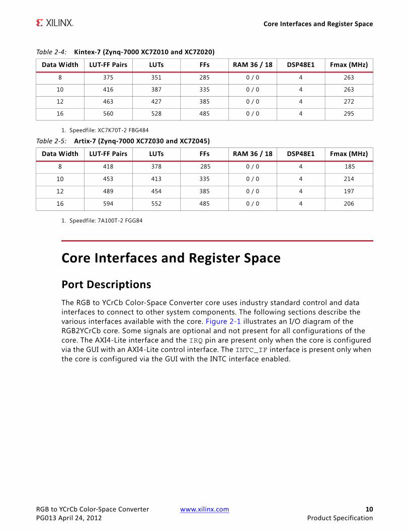
Port DescriptionsThe RGB to YCrCb Color-Space Converter core uses industry standard control and data interfaces to connect to other system components. The following sections describe the various interfaces available with the core. Figure 2-1 illustrates an I/O diagram of the RGB2YCrCb core. Some signals are optional and not present for all configurations of the core. The AXI4-Lite interface and the IRQ pin are present only when the core is configured via the GUI with an AXI4-Lite control interface. The INTC_IF interface is present only when the core is configured via the GUI with the INTC interface enabled.
Table 2-4: Kintex-7 (Zynq-7000 XC7Z010 and XC7Z020)
Data Width LUT-FF Pairs LUTs FFs RAM 36 / 18 DSP48E1 Fmax (MHz)
8 375 351 285 0 / 0 4 263
10 416 387 335 0 / 0 4 263
12 463 427 385 0 / 0 4 272
16 560 528 485 0 / 0 4 295
Table 2-5: Artix-7 (Zynq-7000 XC7Z030 and XC7Z045)
Data Width LUT-FF Pairs LUTs FFs RAM 36 / 18 DSP48E1 Fmax (MHz)
8 418 378 285 0 / 0 4 185
10 453 413 335 0 / 0 4 214
12 489 454 385 0 / 0 4 197
16 594 552 485 0 / 0 4 206

RGB to YCrCb Color-Space Converter www.xilinx.com 11PG013 April 24, 2012 Product Specification
Core Interfaces and Register Space
Common Interface SignalsTable 2-6 summarizes the signals which are either shared by, or not part of the dedicated AXI4-Stream data or AXI4-Lite control interfaces.
The ACLK, ACLKEN and ARESETn signals are shared between the core, the AXI4-Stream data interfaces, and the AXI4-Lite control interface. Refer to The Interrupt Subsystem for a detailed description of the INTC_IF and IRQ pins.
X-Ref Target - Figure 2-1
Figure 2-1: RGB2YCrCb Core Top-Level Signaling Interface
Table 2-6: Common Interface Signals
Signal Name Direction Width Description
ACLK In 1 Clock
ACLKEN In 1 Clock Enable
ARESETn In 1 Active low synchronous
INTC_IF Out 6 Optional External Interrupt Controller Interface. Available only when INTC_IF is selected on GUI.
IRQ Out 1 Optional Interrupt Request Pin. Available only when AXI4-Liter interface is selected on GUI.

RGB to YCrCb Color-Space Converter www.xilinx.com 12PG013 April 24, 2012 Product Specification
Core Interfaces and Register Space
ACLK
All signals, including the AXI4-Stream and AXI4-Lite component interfaces, must be synchronous to the core clock signal ACLK. All interface input signals are sampled on the rising edge of ACLK. All output signal changes occur after the rising edge of ACLK.
ACLKEN
The ACLKEN pin is an active-high, synchronous clock-enable input pertaining to both the AXI4-Stream and AXI4-Lite interfaces. Setting ACLKEN low (de-asserted) halts the operation of the core despite rising edges on the ACLK pin. Internal states are maintained, and output signal levels are held until ACLKEN is asserted again. When ACLKEN is de-asserted, core inputs are not sampled, except ARESETn, which supersedes ACLKEN.
ARESETn
The ARESETn pin is an active-low, synchronous reset input pertaining to both the AXI4-Stream and AXI4-Lite interfaces. ARESETn supersedes ACLKEN, and when set to 0, the core resets at the next rising edge of ACLK even if ACLKEN is de-asserted.
Data InterfaceThe RGB2YCrCb core receives and transmits data using AXI4-Stream interfaces that implement a video protocol as defined in the Video IP: AXI Feature Adoption section of the UG761 AXI Reference Guide.
AXI4-Stream Signal Names and Descriptions
Table 2-7 describes the AXI4-Stream signal names and descriptions.
Table 2-7: AXI4-Stream Data Interface Signal Descriptions
Signal Name Direction Width Description
s_axis_video_tdata In 24,32,40,48 Input Video Data
s_axis_video_tvalid In 1 Input Video Valid Signal
s_axis_video_tready Out 1 Input Ready
s_axis_video_tuser In 1 Input Video Start Of Frame
s_axis_video_tlast In 1 Input Video End Of Line
m_axis_video_tdata Out 24,32,40,48 Output Video Data
m_axis_video_tvalid Out 1 Output Valid
m_axis_video_tready In 1 Output Ready
m_axis_video_tuser Out 1 Output Video Start Of Frame
m_axis_video_tlast Out 1 Output Video End Of Line

RGB to YCrCb Color-Space Converter www.xilinx.com 13PG013 April 24, 2012 Product Specification
Core Interfaces and Register Space
Video Data
The AXI4-Stream interface specif ication restricts TDATA widths to integer multiples of 8 bits. Therefore, 10 and 12 bit data must be padded with zeros on the MSB to form Nx8 bit wide vector before connecting to s_axis_video_tdata. Padding does not affect the size of the core.
For example, RGB data on the RGB2YCrCb input s_axis_video_tdata is packed and padded to multiples of 8 bits as necessary, as seen in Figure 2-2. Zero padding the most signif icant bits is only necessary for 10 and 12 bit wide data.
READY/VALID Handshake
A valid transfer occurs whenever READY, VALID, ACLKEN, and ARESETn are high at the rising edge of ACLK, as seen in Figure 2-3. During valid transfers, DATA only carries active video data. Blank periods and ancillary data packets are not transferred via the AXI4-Stream video protocol.
Guidelines on Driving s_axis_video_tvalid
Once s_axis_video_tvalid is asserted, no interface signals (except the RGB2YCrCb core driving s_axis_video_tready) may change value until the transaction completes (s_axis_video_tready, and s_axis_video_tvalid ACLKEN are high on the rising edge of ACLK). Once asserted, s_axis_video_tvalid may only be de-asserted after a transaction has completed. Transactions may not be retracted or aborted. In any cycle following a transaction, s_axis_video_tvalid can either be de-asserted or remain asserted to initiate a new transfer.
X-Ref Target - Figure 2-2
Figure 2-2: RGB Data Encoding on s_axis_video_tdata
X-Ref Target - Figure 2-3
Figure 2-3: Example of READY/VALID Handshake, Start of a New Frame

RGB to YCrCb Color-Space Converter www.xilinx.com 14PG013 April 24, 2012 Product Specification
Core Interfaces and Register Space
Guidelines on Driving m_axis_video_tready
The m_axis_video_tready signal may be asserted before, during or after the cycle in which the RGB2YCrCb core asserted m_axis_video_tvalid. The assertion of m_axis_video_tready may be dependent on the value of m_axis_video_tvalid. A slave that can immediately accept data qualif ied by m_axis_video_tvalid, should pre-assert its m_axis_video_tready signal until data is received. Alternatively, m_axis_video_tready can be registered and driven the cycle following VALID assertion. It is recommended that the AXI4-Stream slave should drive READY independently, or pre-assert READY to minimize latency.
Start of Frame Signals - m_axis_video_tuser0, s_axis_video_tuser0
The Start-Of-Frame (SOF) signal, physically transmitted over the AXI4-Stream TUSER0 signal, marks the f irst pixel of a video frame. The SOF pulse is 1 valid transaction wide, and must coincide with the first pixel of the frame, as seen in Figure 2-3. SOF serves as a frame synchronization signal, which allows downstream cores to re-initialize, and detect the f irst pixel of a frame. The SOF signal may be asserted an arbitrary number of ACLK cycles before the first pixel value is presented on DATA , as long as a VALID is not asserted.
End of Line Signals - m_axis_video_tlast, s_axis_video_tlast
The End-Of-Line signal, physically transmitted over the AXI4-Stream TLAST signal, marks the last pixel of a line. The EOL pulse is 1 valid transaction wide, and must coincide with the last pixel of a scan-line, as seen in Figure 2-4.
Control InterfaceWhen configuring the core, the user has the option to add an AXI4-Lite register interface to dynamically control the behavior of the core. The AXI4-Lite slave interface facilitates integrating the core into a processor system, or along with other video or AXI4-Lite compliant IP, connected via AXI4-Lite interface to an AXI4-Lite master. In a static configuration with a fixed set of parameters (constant configuration), the core can be instantiated without the AXI4-Lite control interface, which reduces the core Slice footprint.
X-Ref Target - Figure 2-4
Figure 2-4: Use of EOL and SOF Signals
RGB to YCrCb Color-Space Converter www.xilinx.com 15PG013 April 24, 2012 Product Specification
Core Interfaces and Register Space
Constant Configuration
The constant configuration caters to users who will use the core in one setup that will not need to change over time. In constant configuration the image resolution (number of active pixels per scan line and the number of active scan lines per frame), and the other core parameters are hard coded into the core via the RGB2YCrCb core GUI. Since there is no AXI4-Lite interface, the core is not programmable, but can be reset, enabled, or disabled using the ARESETn and ACLKEN ports.
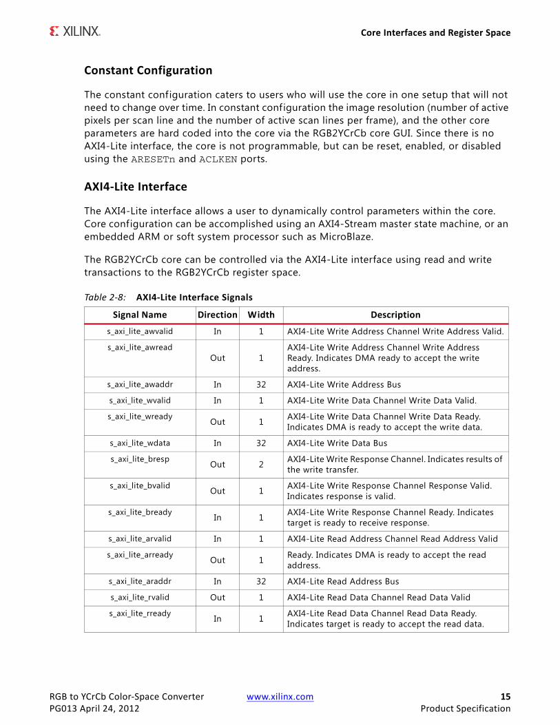
AXI4-Lite Interface
The AXI4-Lite interface allows a user to dynamically control parameters within the core. Core configuration can be accomplished using an AXI4-Stream master state machine, or an embedded ARM or soft system processor such as MicroBlaze.
The RGB2YCrCb core can be controlled via the AXI4-Lite interface using read and write transactions to the RGB2YCrCb register space.
Table 2-8: AXI4-Lite Interface Signals
Signal Name Direction Width Description
s_axi_lite_awvalid In 1 AXI4-Lite Write Address Channel Write Address Valid.
s_axi_lite_awreadOut 1
AXI4-Lite Write Address Channel Write Address Ready. Indicates DMA ready to accept the write address.
s_axi_lite_awaddr In 32 AXI4-Lite Write Address Bus
s_axi_lite_wvalid In 1 AXI4-Lite Write Data Channel Write Data Valid.
s_axi_lite_wready Out 1 AXI4-Lite Write Data Channel Write Data Ready. Indicates DMA is ready to accept the write data.
s_axi_lite_wdata In 32 AXI4-Lite Write Data Bus
s_axi_lite_bresp Out 2 AXI4-Lite Write Response Channel. Indicates results of the write transfer.
s_axi_lite_bvalid Out 1 AXI4-Lite Write Response Channel Response Valid. Indicates response is valid.
s_axi_lite_bready In 1 AXI4-Lite Write Response Channel Ready. Indicates target is ready to receive response.
s_axi_lite_arvalid In 1 AXI4-Lite Read Address Channel Read Address Valid
s_axi_lite_arready Out 1 Ready. Indicates DMA is ready to accept the read address.
s_axi_lite_araddr In 32 AXI4-Lite Read Address Bus
s_axi_lite_rvalid Out 1 AXI4-Lite Read Data Channel Read Data Valid
s_axi_lite_rready In 1 AXI4-Lite Read Data Channel Read Data Ready. Indicates target is ready to accept the read data.

RGB to YCrCb Color-Space Converter www.xilinx.com 16PG013 April 24, 2012 Product Specification
Core Interfaces and Register Space
Register SpaceThe standardized Xilinx Video IP register space is partitioned to control-, timing-, and core specific registers. The RGB2YCrCb core uses only one timing related register, ACTIVE_SIZE (0x0020), which allows specifying the input frame dimensions. The core has thirteen core specific registers which allow the user to dynamically control the operation of the core.
s_axi_lite_rdata Out 32 AXI4-Lite Read Data Bus
s_axi_lite_rresp Out 2 AXI4-Lite Read Response Channel Response. Indicates results of the read transfer.
Table 2-8: AXI4-Lite Interface Signals (Cont’d)
Signal Name Direction Width Description
Table 2-9: Register Names and Descriptions
Address (hex)
BASEADDR +
Register Name Access Type
Double Buffered Default Value Register Description
0x0000 CONTROL R/W N Power-on-Reset: 0x0
Bit 0: SW_ENABLE Bit 1: REG_UPDATE Bit 4: BYPASS(1) Bit 5: TEST_PATTERN(1) Bit 30: FRAME_SYNC_RESET (1: reset) Bit 31: SW_RESET (1: reset)
0x0004 STATUS R/W No 0Bit 0: PROC_STARTED Bit 1: EOF Bit 16: SLAVE_ERROR
0x0008 ERROR R/W No 0
Bit 0: SLAVE_EOL_EARLY Bit 1: SLAVE_EOL_LATE Bit 2: SLAVE_SOF_EARLY Bit 3: SLAVE_SOF_LATE
0x000C IRQ_ENABLE R/W No 0 16-0: Interrupt enable bits corresponding to STATUS bits
0x0010 VERSION R N/A 0x0500a000
7-0: REVISION_NUMBER 11-8: PATCH_ID 15-12: VERSION_REVISION 23-16: VERSION_MINOR 31-24: VERSION_MAJOR
0x0014 SYSDEBUG0 R N/A 0 0-31: Frame Throughput monitor(1)
0x0018 SYSDEBUG1 R N/A 0 0-31: Line Throughput monitor(1)
0x001C SYSDEBUG2 R N/A 0 0-31: Pixel Throughput monitor(1)

RGB to YCrCb Color-Space Converter www.xilinx.com 17PG013 April 24, 2012 Product Specification
Core Interfaces and Register Space
1. Only available when the debugging features option is enabled in the GUI at the time the core is instantiated.
CONTROL (0x0000) Register
Bit 0 of the CONTROL register, SW_ENABLE, facilitates enabling and disabling the core from software. Writing '0' to this bit effectively disables the core halting further operations, which blocks the propagation of all video signals. After Power up, or Global Reset, the SW_ENABLE defaults to 0 for the AXI4-Lite interface. Similar to the ACLKEN pin, the SW_ENABLE flag is not synchronized with the AXI4-Stream interfaces: Enabling or Disabling the core takes effect immediately, irrespective of the core processing status. Disabling the core for extended periods may lead to image tearing.
Bit 1 of the CONTROL register, REG_UPDATE is a write done semaphore for the host processor, which facilitates committing all user and timing register updates simultaneously. The RGB2YCrCb core ACTIVE_SIZE and core specif ic registers are double buffered. One set of registers (the processor registers) is directly accessed by the processor interface, while the other set (the active set) is actively used by the core. New values written to the processor registers will get copied over to the active set at the end of the AXI4-Stream frame, if and only if REG_UPDATE is set. Setting REG_UPDATE to 0 before updating multiple register values, then setting REG_UPDATE to 1 when updates are completed ensures all registers are updated simultaneously at the frame boundary without causing image tearing.
0x0020 ACTIVE_SIZE R/W Yes Specified via GUI
12-0: Number of Active Pixels per Scanline 28-16: Number of Active Lines per Frame
0x0100 YMAX R/W Yes Specified via GUI 15:0: Luma clipping value
0x0104 YMIN R/W Yes Specified via GUI 15:0: Luma clamping value
0x0108 CbMAX R/W Yes Specified via GUI 15:0: Chroma Cb clippling value
0x010C CbMIN R/W Yes Specified via GUI 15:0: Chroma Cb clamping value
0x0110 CrMAX R/W Yes Specified via GUI 15:0: Chroma Cr clippling value
0x0114 CrMIN R/W Yes Specified via GUI 15:0: Chroma Cr clamping value
0x0118 YOFFSET R/W Yes Specified via GUI 16:0: Luma offset compensation
0x011C CbOFFSET R/W Yes Specified via GUI 16:0: Chroma (Cb) offset compensation
0x0120 CrOFFSET R/W Yes Specified via GUI 16:0: Chroma (Cr) offset compensation
0x0124 ACOEF R/W Yes Specified via GUI 17:0: ACOEF, BCOEF, CCOEF, DCOEF are derived from CA, CB, CC and CD, by
representing the floating point coefficients in 17-bit wide signed integer
format.
0x0128 BCOEF R/W Yes Specified via GUI
0x012C CCOEF R/W Yes Specified via GUI
0x0130 DCOEF R/W Yes Specified via GUI
Table 2-9: Register Names and Descriptions (Cont’d)
Address (hex)
BASEADDR +
Register Name Access Type
Double Buffered Default Value Register Description

RGB to YCrCb Color-Space Converter www.xilinx.com 18PG013 April 24, 2012 Product Specification
Core Interfaces and Register Space
Bit 4 of the CONTROL register, BYPASS, switches the core to bypass mode if debug features are enabled. In bypass mode the RGB2YCrCb core processing function is bypassed, and the core repeats AXI4-Stream input samples on its output. Refer to Debugging Features in Appendix C for more information. If debug features were not included at instantiation, this flag has no effect on the operation of the core. Switching bypass mode on or off is not synchronized to frame processing, therefore can lead to image tearing.
Bit 5 of the CONTROL register, TEST_PATTERN, switches the core to test-pattern generator mode if debug features are enabled. Refer to Debugging Features in Appendix C for more information. If debug features were not included at instantiation, this flag has no effect on the operation of the core. Switching test-pattern generator mode on or off is not synchronized to frame processing, therefore can lead to image tearing.
Bits 30 and 31 of the CONTROL register, FRAME_SYNC_RESET and SW_RESET facilitate software reset. Setting SW_RESET reinitializes the core to GUI default values, all internal registers and outputs are cleared and held at initial values until SW_RESET is set to 0. The SW_RESET flag is not synchronized with the AXI4-Stream interfaces. Resetting the core while frame processing is in progress will cause image tearing. For applications where the soft-ware reset functionality is desirable, but image tearing has to be avoided a frame synchronized software reset (FRAME_SYNC_RESET) is available. Setting FRAME_SYNC_RESET to 1 will reset the core at the end of the frame being processed, or immediately if the core is between frames when the FRAME_SYNC_RESET was asserted. After reset, the FRAME_SYNC_RESET bit is automatically cleared, so the core can get ready to process the next frame of video as soon as possible. The default value of both RESET bits is 0. Core instances with no AXI4-Lite control interface can only be reset via the ARESETn pin.
STATUS (0x0004) Register
All bits of the STATUS register can be used to request an interrupt from the host processor. To facilitate identif ication of the interrupt source, bits of the STATUS register remain set after an event associated with the particular STATUS register bit, even if the event condition is not present at the time the interrupt is serviced.
Bits of the STATUS register can be cleared individually by writing '1' to the bit position to be cleared.
Bit 0 of the STATUS register, PROC_STARTED, indicates that processing of a frame has commenced via the AXI4-Stream interface.
Bit 1 of the STATUS register, End-of-frame (EOF), indicates that the processing of a frame has completed.
Bit 16 of the STATUS register, SLAVE_ERROR, indicates that one of the conditions monitored by the ERROR register has occurred.

RGB to YCrCb Color-Space Converter www.xilinx.com 19PG013 April 24, 2012 Product Specification
Core Interfaces and Register Space
ERROR (0x0008) Register
Bit 16 of the STATUS register, SLAVE_ERROR, indicates that one of the conditions monitored by the ERROR register has occurred. This bit can be used to request an interrupt from the host processor. To facilitate identif ication of the interrupt source, bits of the STATUS and ERROR registers remain set after an event associated with the particular ERROR register bit, even if the event condition is not present at the time the interrupt is serviced.
Bits of the ERROR register can be cleared individually by writing '1' to the bit position to be cleared.
Bit 0 of the ERROR register, EOL_EARLY, indicates an error during processing a video frame via the AXI4-Stream slave port. The number of pixels received between the latest and the preceding End-Of-Line (EOL) signal was less than the value programmed into the ACTIVE_SIZE register.
Bit 1 of the ERROR register, EOL_LATE, indicates an error during processing a video frame via the AXI4-Stream slave port. The number of pixels received between the last EOL signal surpassed the value programmed into the ACTIVE_SIZE register.
Bit 2 of the ERROR register, SOF_EARLY, indicates an error during processing a video frame via the AXI4-Stream slave port. The number of pixels received between the latest and the preceding Start-Of-Frame (SOF) signal was less than the value programmed into the ACTIVE_SIZE register.
Bit 3 of the ERROR register, SOF_LATE, indicates an error during processing a video frame via the AXI4-Stream slave port. The number of pixels received between the last SOF signal surpassed the value programmed into the ACTIVE_SIZE register.
IRQ_ENABLE (0x000C) Register
Any bits of the STATUS register can generate a host-processor interrupt request via the IRQ pin. The Interrupt Enable register facilitates selecting which bits of STATUS register will assert IRQ. Bits of the STATUS registers are masked by (AND) corresponding bits of the IRQ_ENABLE register and the resulting terms are combined (OR) together to generate IRQ.
Version (0x0010) Register
Bit f ields of the Version Register facilitate software identif ication of the exact version of the hardware peripheral incorporated into a system. The core driver can take advantage of this Read-Only value to verify that the software is matched to the correct version of the hardware. See Table 2-9 for details.
SYSDEBUG0 (0x0014) Register
The SYSDEBUG0, or Frame Throughput Monitor, register indicates the number of frames processed since power-up or the last time the core was reset. The SYSDEBUG registers can

RGB to YCrCb Color-Space Converter www.xilinx.com 20PG013 April 24, 2012 Product Specification
Core Interfaces and Register Space
be useful to identify external memory / Frame buffer / or throughput bottlenecks in a video system. Refer to Debugging Features in Appendix C for more information.
SYSDEBUG1 (0x0018) Register
The SYSDEBUG1, or Line Throughput Monitor, register indicates the number of lines processed since power-up or the last time the core was reset. The SYSDEBUG registers can be useful to identify external memory / Frame buffer / or throughput bottlenecks in a video system. Refer to Debugging Features in Appendix C for more information.
SYSDEBUG2 (0x001C) Register
The SYSDEBUG2, or Pixel Throughput Monitor, register indicates the number of pixels processed since power-up or the last time the core was reset. The SYSDEBUG registers can be useful to identify external memory / Frame buffer / or throughput bottlenecks in a video system. Refer to Debugging Features in Appendix C for more information.
ACTIVE_SIZE (0x0020) Register
The ACTIVE_SIZE register encodes the number of active pixels per scan line and the number of active scan lines per frame. The lower half-word (bits 12:0) encodes the number of active pixels per scan line. Supported values are between 32 and the value provided in the Maximum number of pixels per scan line f ield in the GUI. The upper half-word (bits 28:16) encodes the number of active scan lines per frame. Supported values are 32 to 7680. To avoid processing errors, the user should restrict values written to ACTIVE_SIZE to the range supported by the core instance.
YMAX (0x0100) Register
The YMAX register holds the maximum value allowed on the Luma (Y) channel of the output. If the output data is greater than this value, then this value replaces it on the output. This register is only valid if Outputs Clipped is selected in the core parameterization GUI.
YMIN (0x0104) Register
The YMin register holds the minimum value allowed on the Luma (Y) channel of the output. If the output data is less than this value, then this value replaces it on the output. This register is only valid if Outputs Clipped is selected in the core parameterization GUI.
CbMax (0x0108) Register
The CbMAX register holds the maximum value allowed on the Cb Chroma channel of the output. If the output data is greater than this value, then this value replaces it on the output. This register is only valid if Outputs Clipped is selected in the core parameterization GUI.
RGB to YCrCb Color-Space Converter www.xilinx.com 21PG013 April 24, 2012 Product Specification
Core Interfaces and Register Space
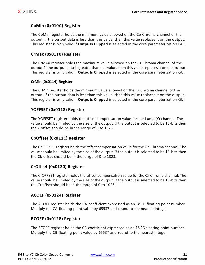
CbMin (0x010C) Register
The CbMin register holds the minimum value allowed on the Cb Chroma channel of the output. If the output data is less than this value, then this value replaces it on the output. This register is only valid if Outputs Clipped is selected in the core parameterization GUI.
CrMax (0x0110) Register
The CrMAX register holds the maximum value allowed on the Cr Chroma channel of the output. If the output data is greater than this value, then this value replaces it on the output. This register is only valid if Outputs Clipped is selected in the core parameterization GUI.
CrMin (0x0114) Register
The CrMin register holds the minimum value allowed on the Cr Chroma channel of the output. If the output data is less than this value, then this value replaces it on the output. This register is only valid if Outputs Clipped is selected in the core parameterization GUI.
YOFFSET (0x0118) Register
The YOFFSET register holds the offset compensation value for the Luma (Y) channel. The value should be limited by the size of the output. If the output is selected to be 10-bits then the Y offset should be in the range of 0 to 1023.
CbOffset (0x011C) Register
The CbOFFSET register holds the offset compensation value for the Cb Chroma channel. The value should be limited by the size of the output. If the output is selected to be 10-bits then the Cb offset should be in the range of 0 to 1023.
CrOffset (0x0120) Register
The CrOFFSET register holds the offset compensation value for the Cr Chroma channel. The value should be limited by the size of the output. If the output is selected to be 10-bits then the Cr offset should be in the range of 0 to 1023.
ACOEF (0x0124) Register
The ACOEF register holds the CA coeff icient expressed as an 18.16 floating point number. Multiply the CA floating point value by 65537 and round to the nearest integer.
BCOEF (0x0128) Register
The BCOEF register holds the CB coeff icient expressed as an 18.16 floating point number. Multiply the CB floating point value by 65537 and round to the nearest integer.

RGB to YCrCb Color-Space Converter www.xilinx.com 22PG013 April 24, 2012 Product Specification
Core Interfaces and Register Space
CCOEF (0x012C) Register
The CCOEF register holds the CC coeff icient expressed as an 18.16 floating point number. Multiply the CC floating point value by 65537 and round to the nearest integer.
DCOEF (0x0130) Register
The DCOEF register holds the CD coeff icient expressed as an 18.16 floating point number. Multiply the CD floating point value by 65537 and round to the nearest integer.
The Interrupt Subsystem
STATUS register bits can trigger interrupts so embedded application developers can quickly identify faulty interfaces or incorrectly parameterized cores in a video system. Irrespective of whether the AXI4-Lite control interface is present or not, the RGB2YCrCb core detects AXI4-Stream framing errors, as well as the beginning and the end of frame processing.
When the core is instantiated with an AXI4-Lite Control interface, the optional interrupt request pin (IRQ) is present. Events associated with bits of the STATUS register can generate a (level triggered) interrupt, if the corresponding bits of the interrupt enable register (IRQ_ENABLE) are set. Once set by the corresponding event, bits of the STATUS register stay set until the user application clears them by writing '1' to the desired bit positions. Using this mechanism the system processor can identify and clear the interrupt source.
Without the AXI4-Lite interface the user can still benefit from the core signaling error and status events. By selecting the Enable INTC Port check-box on the GUI, the core generates the optional INTC_IF port. This vector of signals gives parallel access to the individual interrupt sources, as seen in Table 2-10.
Unlike STATUS and ERROR flags, INTC_IF signals are not held, rather stay asserted only while the corresponding event persists.
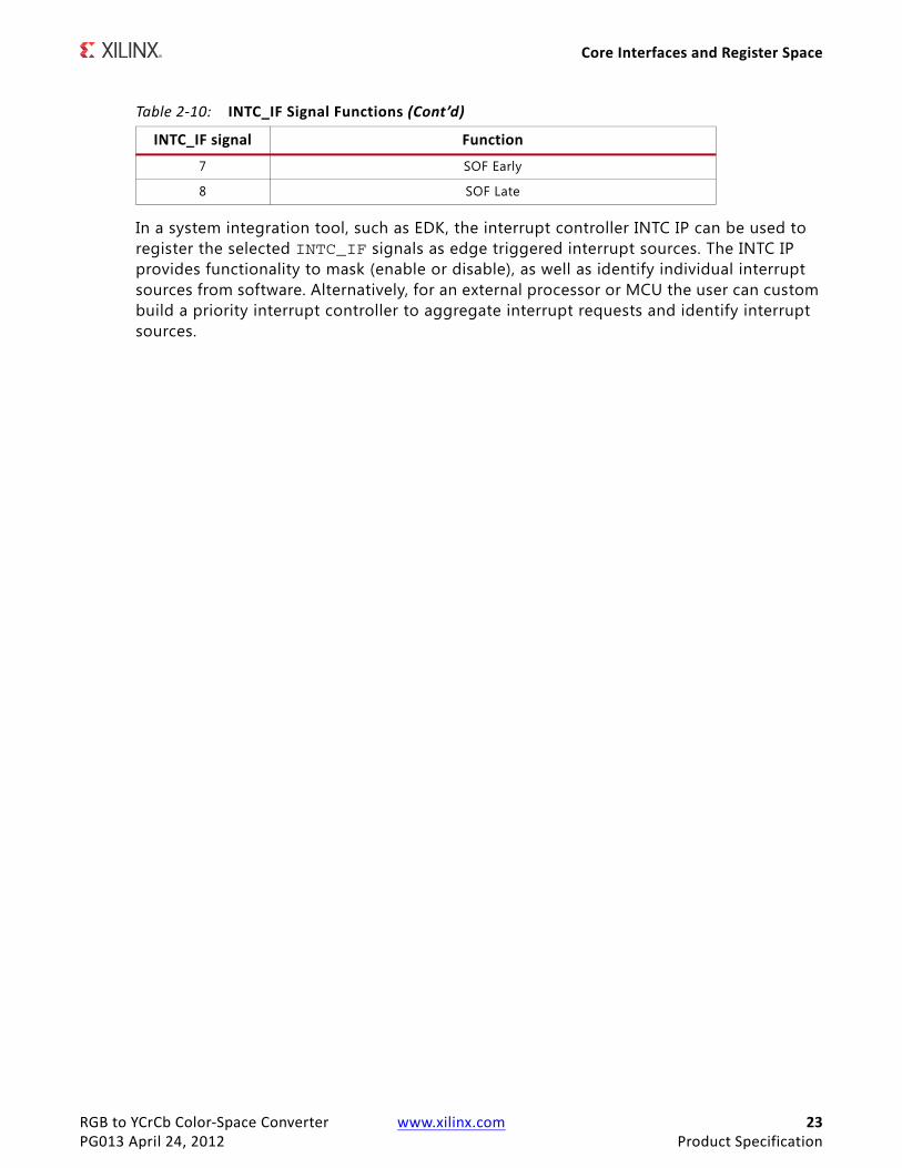
Table 2-10: INTC_IF Signal Functions
INTC_IF signal Function
0 Frame processing start
1 Frame processing complete
2 Reserved
3 Reserved
4 Video over AXI4-Stream Error
5 EOL Early
6 EOL Late
RGB to YCrCb Color-Space Converter www.xilinx.com 23PG013 April 24, 2012 Product Specification
Core Interfaces and Register Space
In a system integration tool, such as EDK, the interrupt controller INTC IP can be used to register the selected INTC_IF signals as edge triggered interrupt sources. The INTC IP provides functionality to mask (enable or disable), as well as identify individual interrupt sources from software. Alternatively, for an external processor or MCU the user can custom build a priority interrupt controller to aggregate interrupt requests and identify interrupt sources.
7 SOF Early
8 SOF Late
Table 2-10: INTC_IF Signal Functions (Cont’d)
INTC_IF signal Function

RGB to YCrCb Color-Space Converter www.xilinx.com 24PG013 April 24, 2012
Chapter 3
Customizing and Generating the CoreThis chapter includes information on using Xilinx tools to customize and generate the core.
Graphical User Interface The main screen of the Graphical User Interface (GUI) of CORE Generator (shown in Figure 3-1) and EDK (shown in Figure 3-3) allows quick implementation of standard RGB to YCrCb 4:4:4 or RGB to YUV 4:4:4 converter without having to manually enter values from Table 4-2 though Table 4-4. The Color-Space Converter core also supports proprietary (non-standard) converter implementations. This is done by selecting “custom” from the Standard Selection drop-down menu, as long as the custom conversion matrix can be transformed to the form of Equation 4-5.

RGB to YCrCb Color-Space Converter www.xilinx.com 25PG013 April 24, 2012
Graphical User Interface
The main screen is shown in Figure 3-1. Descriptions of the options provided in the GUI screens are included in this section.
The first page of the GUI displays the following options:
• Component Name: The component name is used as the base name of output files generated for the module. Names must begin with a letter and must be composed from characters a to z, 0 to 9 and “_”. The component name v_rgb2ycrcb_v5_00_a is not a valid component name and should not be used.
• Data Width: Specifies the bit width of input samples. Permitted values are 8, 10, 12 and 16 bits.
• Number of Active Pixels per Scan line: When the AXI4-Lite control interface is enabled, the generated core will use the value specified in the CORE Generator GUI as the default value for the lower half-word of the ACTIVE_SIZE register. When an AXI4-Lite interface is not present, the GUI selection permanently defines the horizontal size of the frames the generated core instance is to process.
• Number of Active Lines per Frame: When the AXI4-Lite control interface is enabled, the generated core will use the value specif ied in the CORE Generator GUI as the default value for the upper half-word of the ACTIVE_SIZE register. When an AXI4-Lite
X-Ref Target - Figure 3-1
Figure 3-1: Color-Space Converter Main Screen
RGB to YCrCb Color-Space Converter www.xilinx.com 26PG013 April 24, 2012
Graphical User Interface
interface is not present, the GUI selection permanently defines the vertical size (number of lines) of the frames the generated core instance is to process.
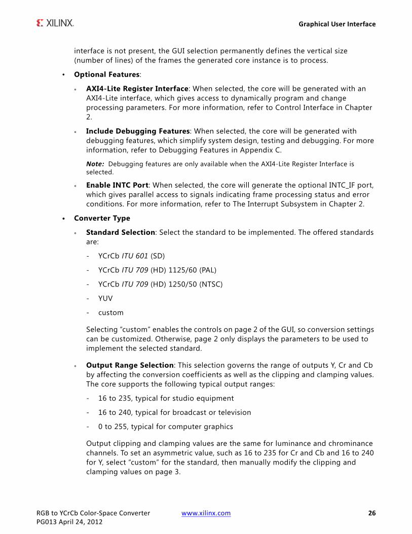
• Optional Features:
° AXI4-Lite Register Interface: When selected, the core will be generated with an AXI4-Lite interface, which gives access to dynamically program and change processing parameters. For more information, refer to Control Interface in Chapter 2.
° Include Debugging Features: When selected, the core will be generated with debugging features, which simplify system design, testing and debugging. For more information, refer to Debugging Features in Appendix C.
Note: Debugging features are only available when the AXI4-Lite Register Interface is selected.
° Enable INTC Port: When selected, the core will generate the optional INTC_IF port, which gives parallel access to signals indicating frame processing status and error conditions. For more information, refer to The Interrupt Subsystem in Chapter 2.
• Converter Type
° Standard Selection: Select the standard to be implemented. The offered standards are:
- YCrCb ITU 601 (SD)
- YCrCb ITU 709 (HD) 1125/60 (PAL)
- YCrCb ITU 709 (HD) 1250/50 (NTSC)
- YUV
- custom
Selecting “custom” enables the controls on page 2 of the GUI, so conversion settings can be customized. Otherwise, page 2 only displays the parameters to be used to implement the selected standard.
° Output Range Selection: This selection governs the range of outputs Y, Cr and Cb by affecting the conversion coeff icients as well as the clipping and clamping values. The core supports the following typical output ranges:
- 16 to 235, typical for studio equipment
- 16 to 240, typical for broadcast or television
- 0 to 255, typical for computer graphics
Output clipping and clamping values are the same for luminance and chrominance channels. To set an asymmetric value, such as 16 to 235 for Cr and Cb and 16 to 240 for Y, select “custom” for the standard, then manually modify the clipping and clamping values on page 3.

RGB to YCrCb Color-Space Converter www.xilinx.com 27PG013 April 24, 2012
Graphical User Interface
The previously-mentioned ranges are characteristic for 8-bit outputs. If 10- or 12-bit outputs are used, the ranges are extended proportionally. For example, 16 to 240 mode for 10-bit outputs will result in output values ranging from 64 to 960.
The Conversion Matrix, Offset Compensation, Clipping and Clamping screen (Figure 3-2) displays and enables editing of conversion coefficients, similar to Equation 4-9, Equation 4-10 and Equation 4-11. Contents are editable only when “custom” is selected as the standard on page 1.
• Conversion Matrix: Enter floating-point conversion constants, ranging from 0 to 1, into the four f ields representing CA, CB, CC and CD.
• Offset Compensation: Enter the offset compensation constants (YOFFSET, CbOffset, and CrOffset in Equation 4-9, Equation 4-10 and Equation 4-11). These constants are scaled to the output representation. If OY and OC are in the 0.0 – 1.0 range, and the output is represented as 10-bit unsigned integers, then luminance and chrominance offsets should be entered as integers in the 0-1023 range.
• Outputs Clipped/Outputs Clamped: These check boxes control whether clipping/clamping logic will be instantiated in the generated netlist. The clipping/clamping logic ensures no arithmetic wrap-arounds happen at the expense of extra slice-based logic resources.
X-Ref Target - Figure 3-2
Figure 3-2: Conversion Matrix, Offset Compensation, Clipping and Clamping Screen

RGB to YCrCb Color-Space Converter www.xilinx.com 28PG013 April 24, 2012
Graphical User Interface
• Minimum and Maximum Values: Similar to offset values, the edit-boxes take unsigned integer values in the range permitted by the current output representation.
Definitions of the EDK GUI controls are identical to the corresponding CORE Generator GUI functions.
X-Ref Target - Figure 3-3
Figure 3-3: RGB to YCrCb Color-Space Converter, EDK GUI Screen

RGB to YCrCb Color-Space Converter www.xilinx.com 29PG013 April 24, 2012
Parameter Values in the XCO File
Parameter Values in the XCO FileTable 3-1 defines valid entries for the XCO parameters. Xilinx strongly suggests that XCO parameters are not manually edited in the XCO file; instead, use the CORE Generator software GUI to configure the core and perform range and parameter value checking. The XCO parameters are helpful in defining the interface to other Xilinx tools.
Table 3-1: XCO Parameters
XCO Parameter Default Values
component_name v_rgb2ycrcb_v5_00_a_u0
s_axis_video_data_width 8
acoef 0.299
bcoef 0.114
ccoef 0.713
dcoef 0.564
cbmin 16
cbmax 240
cbmin 16
crmax 16
crmin 240
ymax 240
cboffset 128
croffset 128
yoffset 16
has_clamp true
has_clip true
input_range 16_to_240_for TV
standard_sel SD_ITU_601
active_cols 1920
active_rows 1080
has_axi4_lite false
has_debug false
has_intc_if false

RGB to YCrCb Color-Space Converter www.xilinx.com 30PG013 April 24, 2012
Output Generation
Output GenerationCORE Generator will output the core as a netlist that can be inserted directly in an HDL design. EDK will output the core as a pCore that can be inserted into an EDK Project. The output is placed in the <project directory>.
File DetailsThe CORE Generator output consists of some or all the following files.
Name Description
<component_name>_readme.txt Readme file for the core.
<component_name>.ngc The netlist for the core.
<component_name>.veoThe HDL template for instantiating the core.
<component_name>.vho
<component_name>.v The structural simulation model for the core. It is used for functionally simulating the core.<component_name>.vhd
<component_name>.xcoLog f ile from CORE Generator software describing which options
were used to generate the core. An XCO file can also be used as an input to the CORE Generator software.

RGB to YCrCb Color-Space Converter www.xilinx.com 31PG013 April 24, 2012
Chapter 4
Designing with the Core
General Design GuidelinesThe RGB to YCrCb core converts RGB video into YCrCb 4:4:4 or YUV 4:4:4 video. The core processes samples provided via an AXI4-Stream Video protocol slave interface, outputs pixels via an AXI4-Stream Video protocol master interface, and can be controlled via an optional AXI4-Lite interface. The RGB2YCrCb block cannot change the input/output image sizes, the input and output pixel clock rates, or the frame rate. It is recommended that the RGB2YCrCb core is used in conjunction with the Video In to AXI4-Stream and Video Timing Controller cores. The Video Timing Controller core measures the timing parameters, such as number of active scan lines, number of active pixels per scan line of the image sensor. The Video In to AXI4-Stream core converts a standard parallel clocked video interface with syncs and or blanks to AXI4-Stream Video protocol as defined in the Video IP: AXI Feature Adoption section of the UG761 AXI Reference Guide.
Typically, the RGB2YCrCb core is part of larger video system such as an Image Sensor Pipeline (ISP) System shown in Figure 4-1.
X-Ref Target - Figure 4-1
Figure 4-1: Image Sensor Pipeline System with RGB2YCrCb Core

RGB to YCrCb Color-Space Converter www.xilinx.com 32PG013 April 24, 2012
Color-Space Conversion Background
Color-Space Conversion Background
The RGB Color SpaceThe red, green and blue (RGB) color space is widely used throughout computer graphics. Red, green and blue are three primary additive colors: individual components are added together to form a desired color, and are represented by a three dimensional, Cartesian coordinate system, as shown in Figure 4-2.
Table 4-1 presents the RGB values for 100% saturated color bars, a common video test signal.
The RGB color space is the most prevalent choice for computer graphics because color displays use red, green and blue to create the desired color. Also, a system that is designed using the RGB color space can take advantage of a large number of existing software algorithms.
However, RGB is not very eff icient when dealing with real-world images. All three components need equal bandwidth to generate arbitrary colors within the RGB color cube. Also, processing an image in the RGB color space is usually not the most eff icient method. For example, to modify the intensity or color of a given pixel, all three RGB values must be read, modif ied and written back to the frame buffer. If the system had access to the image stored in the intensity and color format, the process would be faster.
R'G'B' Color SpaceWhile the RGB color space is ideal to represent computer graphics, 8-bit linear-light coding performs poorly for images to be viewed. It is necessary to have 12 or 14 bits per component to achieve excellent quality. The best perceptual use of a limited number of bits is made by using nonlinear coding that mimics the nonlinear response of human vision. In video, JPEG, MPEG, computing, digital photography, and many other domains, a nonlinear transfer function is applied to the RGB signals to give nonlinearly coded gamma-corrected components, denoted with symbols R'G'B'. Excellent image quality can be obtained with 10-bit nonlinear coding with a transfer function similar to that of Rec. 709 or RGB.
Table 4-1: 100% RGB Color Bars
Normal Range White Yellow Cyan Green Magenta Red Blue Black
R 0 to 255 255 255 0 0 255 255 0 0
G 0 to 255 255 255 255 255 0 0 0 0
B 0 to 255 255 0 255 0 255 0 255 0

RGB to YCrCb Color-Space Converter www.xilinx.com 33PG013 April 24, 2012
Color-Space Conversion Background
YUV Color SpaceThe YUV color space is used by the analog PAL, NTSC and SECAM color video/TV standards. In the past, black and white systems used only the luminance (Y) information. Chrominance information (U and V) was added in such a way that a black and white receiver can still display a normal black and white picture.
YCrCb (or YCbCr) Color SpaceThe YCrCb or YCbCr color space was developed as part of the ITU-R BT.601 during the development of a world-wide digital component video standard. YCbCr is a scaled, offset version of the YUV color space. Y has a nominal range of 16-235; Cb and Cr have a nominal range of 16-240. There are several YCbCr sampling formats, such as 4:4:4, 4:2:2 and 4:2:0.
Conversion Equations
Derivation of Conversion Equations
To generate the luminance (Y, or gray value) component, biometric experiments were employed to measure how the human eye perceives the intensities of the red, green and blue colors. Based on these experiments, optimal values for coeff icients CA and CB were determined, such that:
Equation 4-1
Actual values for CA and CB differ slightly in different standards.
Conversion from the RGB color space to luminance and chrominance (differential color components) could be described with Equation 4-2.
X-Ref Target - Figure 4-2
Figure 4-2: RGB and YCrCb Color RepresentationsDS657_01_032408
Y CA∗R 1 CA– CB–( )∗G CB∗B+ +=

RGB to YCrCb Color-Space Converter www.xilinx.com 34PG013 April 24, 2012
Color-Space Conversion Background
Equation 4-2
Coefficients CA and CB are chosen between 0 and 1, which guarantees that the range of Y is constrained between the maximum and minimum RGB values permitted, RGBmax and RGBmin respectively.
The minimum and maximum values of R-Y are:
minR-Y= RGBmin – (CA*RGBmin + (1- CA- CB)*RGBmax + CB*RGBmax) = (CA-1) * (RGBmax -RGBmin)
maxR-Y= RGBmax – (CA*RGBmax + (1- CA- CB)*RGBmin + CB*RGBmin) = (1-CA) * (RGBmax -RGBmin)
Thus, the range of R-Y is:
Equation 4-3
Similarly, the minimum and maximum values of B-Y are:
minB-Y=RGBmin-(CA*RGBmax+(1-CA-CB)RGBmax+CB*RGBmin)=(CB-1)(RGBmax-RGBmin)
maxB-Y=RGBmax-(CA*RGBmin+(1-CA-CB)RGBmin+CB*RGBmax)=(1-CB)(RGBmax-RGBmin)
Thus, the range of B-Y is:
Equation 4-4
In most practical implementations, the range of the luminance and chrominance components should be equal. There are two ways to accomplish this: chrominance components (B-Y and R-Y) can be normalized (compressed and offset compensated), or values above and below the luminance range can be clipped.
Both clipping and dynamic range compression result in loss of information; however, the introduced artifacts are different. To leverage differences in the input (RGB) range, different standards choose different trade-offs between clipping and normalization.
The RGB to YCrCb color space conversion core facilitates both range compression and optional clipping and clamping. Range, offset, clipping and clamping levels are parameterizable. The core supports conversions that f it the following general form:
Equation 4-5
YR Y–
B Y–
CA 1 CA– CB– CB1 CA– CA CB 1–+ CB–
CA– CA CB 1–+ 1 CB–
RGB
=
2 CA 1–( ) RGBmax RGBmin–( )
2 CB 1–( ) RGBmax RGBmin–( )
YCR
CB
CA 1 CA– CB– CBCC 1 CA–( ) CC CA CB 1–+( ) CC CB–( )CD CA–( ) CD CA CB 1–+( ) CD 1 CB–( )
RGB
OY
OCr
OCb
+=

RGB to YCrCb Color-Space Converter www.xilinx.com 35PG013 April 24, 2012
Color-Space Conversion Background
CC and CD allow dynamic range compression for R-Y and B-Y, and constants OY, OCr and OCb facilitate offset compensation for the resulting Y, CB and CR components.
Based on Equation 4-3 and Equation 4-4, to constrain the resulting chrominance components (CB and CR) into the [0,1] range, the chrominance offset (OCr and OCb) and the chrominance range compression constants (CC, CD) should be selected as follows (OCr/Cb = 0.5):
Equation 4-6
Equation 4-7
When RGB values are also in the [0,1] range, using the following equations avoids arithmetic under- and overflows (OCr/Cb = 0.5).
Equation 4-8
ITU 601 (SD) and 709 - 1125/60 (NTSC) Standard Conversion Coefficients
CC 12 1 CA–( ) RGBmax RGBmin–( )-------------------------------------------------------------------------------=
CD 12 1 CB–( ) RGBmax RGBmin–( )-------------------------------------------------------------------------------=
CC 12 1 CA–( )------------------------- CD 1
2 1 CB–( )-------------------------= =
Table 4-2: Parameterization Values for the SD (ITU 601) and NTSC HD (ITU 709) Standards
Coefficient/Parameter
Range
16-240 16-235 0-255
CA 0.299 0.2568
CB 0.114 0.0979
CC 0.713 0.7295 0.5910
CD 0.564 0.5772
YOFFSET 2Data_Width-4
Cb/CrOFFSET 2Data_width-1
YMAX 240*2 Data_Width-8 235*2 Data_Width-8 2 OWIDTH-1
Cb/CrMAX 240*2 Data_Width-8 235*2 Data_Width-8 2 OWIDTH-1
YMIN 16*2 Data_Width-8 0
Cb/CrMIN 16*2 Data_Width-8 0

RGB to YCrCb Color-Space Converter www.xilinx.com 36PG013 April 24, 2012
Color-Space Conversion Background
Standard ITU 709 (HD) 1250/50 (PAL)
YUV Standard
Table 4-3: Parameterization Values for the PAL HD (ITU 709) Standard
Coefficient/Parameter
Range
16-240 16-235 0-255
CA 0.2126 0.1819
CB 0.0722 0.0618
CC 0.6350 0.6495 0.6495
CD 0.5389 0.5512
YOFFSET 2Data_Width-4
Cb/CrOFFSET 2Data_Width-1
YMAX 240*2 Data_Width-8 235*2 Data_Width-8 2 Data_Width-1
Cb/CrMAX 240*2 Data_Width-8 235*2 Data_Width-8 2 Data_Width-1
YMIN 16*2 Data_Width-8 0
Cb/CrMIN 16*2 Data_Width-8 0
Table 4-4: Parameterization Values for the YUV Standard
Coefficient/Parameter
Value
16-240 16-235 0-255
CA 0.299
CB 0.114
CC 0.877283
CD 0.492111
YOFFSET 2 Data_Width-4
Cb/CrOFFSET 2 Data_Width-1
YMAX 240*2 Data_Width-8 235*2 Data_Width-8 2 Data_Width-1
Cb/CrMAX 240*2 Data_Width-8 235*2 Data_Width-8 2 Data_Width-1
YMIN 16*2 Data_Width-8 0
Cb/CrMIN 16*2 Data_Width-8 0

RGB to YCrCb Color-Space Converter www.xilinx.com 37PG013 April 24, 2012
Color-Space Conversion Background
Hardware Implementation
The RGB to YCrCb color space transformation equations (Equation 4-5) can be expressed as:
Equation 4-9
Equation 4-10
Equation 4-11
These equations can be directly mapped to the architecture shown in Figure 4-3. The blue boxes in Figure 4-3 represent logic blocks, which are always implemented using XtremeDSP slices.
Error AnalysisThe following analysis, based on DSP fundamentals, presents mean-square-error (MSE) calculations for RGB to YCrCb, assuming IWIDTH bit RGB input data, OWIDTH bit wide YCrCb output data, and 17 bits for coeff icient precision. [Ref 7] arrives to similar results for f ixed coeff icient values and input and output representations.
Taking rounding/quantization into account, the structure illustrated on Figure 4-3 implements the following equations:
Equation 4-12
Equation 4-13
Y CA∗ R G–( ) G CB∗ B G–( ) YOFFSET+ + +=
Cr CC∗ R Y–( ) CrOFFSET+=
Cb CD∗ B Y–( ) CbOFFSET+=
X-Ref Target - Figure 4-3
Figure 4-3: Application Schematic
YOFFSET
Clipping Clamping
Cr
G
R
B
YMAX YMIN
CCOEF
AC
BCDCOEF
Y
CbMWIDTH
DS657_02_032408
Rounding
-
-
MW
IDT
H-2
MWIDTH-1
CBMIN
CRMIN
CBMAX
CRMAX
CBOFFSET
CROFFSET
YRAW ACOEF R G–( )⋅ BCOEF B G–( )⋅+[ ]MWIDTH 2– G+=
Y YRAW[ ]OWIDTH YOFFSET+=

RGB to YCrCb Color-Space Converter www.xilinx.com 38PG013 April 24, 2012
Color-Space Conversion Background
Equation 4-14
Equation 4-15
where [ ]k denotes rounding to k bits. The architecture contains three possible operators that might introduce noise. Quantization noise is inserted when data is rounded.
1. Data is rounded to MWIDTH-2 bits after calculating Yraw,
2. Data is rounded to OWIDTH bits at the output.
3. If CCOEF and DCOEF are chosen such that Cb and Cr may over- or underflow, clipping noise gets inserted to the signal flow.
Before analyzing the effects of these noise sources, f irst look at the input Signal to Quantization Noise Ratio (SQNR). Assuming uniformly distributed quantization error,
Equation 4-16
Substituting LSB =2-INBITS, where INBITS is the input (RGB) precision, SQNRRGB becomes a function of the input dynamic range. In the next three calculations, when calculating SQNRRGB for the typical dynamic ranges, INBITS = 8 for all three cases.
When RGB values are in the (0, 255) range:
Equation 4-17
when RGB values are in the (16, 240) range:
Equation 4-18
and when RGB values are in the (16, 235) range:
Equation 4-19
Cb CCOE B YRAW–( )⋅[ ]OWIDTH CbOFFSET+=
Cr DCOEF R YRAW–( )⋅[ ]OWIDTH CrOFFSET+=
SQNRRGB 10PxPN--------log 10
X2 xdRGBMINRGBMAX1Δ--- e2 xdΔ 2⁄–
Δ 2⁄-------------------------------------------log= =
SQNRRGB 10
1255--------- x2 xd0
255x2 xd1– 2⁄
1 2⁄-------------------------------------log 10
13 255⋅----------------- 2553[ ]
112------
------------------------------------log 54.15dB= = =
SQNRRGB 10
1224--------- x2 xd16
240x2 xd1– 2⁄
1 2⁄-------------------------------------log 53.92dB= =
SQNRRGB 10
1219--------- x2 xd16
235x2 xd1–( ) 2⁄
1 2⁄-------------------------------------log 53.74dB= =

RGB to YCrCb Color-Space Converter www.xilinx.com 39PG013 April 24, 2012
Color-Space Conversion Background
The first rounding noise source can be practically eliminated by the careful choice of MWIDTH. Approximating SQNR by 6.02 MWIDTH [dB], intuitively the rounding noise can be reduced by increasing MWIDTH. However, MWIDTH affects the resource usage and carry chain length in the design (thereby affecting maximum speed). Choosing MWIDTH >18 would significantly increase the dedicated multiplier count of the design.
Therefore, optimal MWIDTH values, in the IWIDTH+4 to 18 range, do not signif icantly increase resource counts but assure that quantization noise inserted is negligible (at least 20 dB less than the input noise).
Output Quantization Noise
Coefficients CC and CD in Equation 4-1 allow standard designers to trade off output quantization and clipping noise. Actual noise inserted depends on the probability statistics of the Cb and Cr variables, but in general if CC and CD are larger than the maximum values calculated in Equation 4-4 and Equation 4-5, output values may clip, introducing clipping noise. However, the lower CC and CD values are chosen, the worse Cb and Cr values will use the available dynamic range, thus introducing more quantization noise. Therefore, the designer's task is to equalize output quantization and clipping noise insertion by carefully choosing CC and CD values knowing the statistics of Cb and Cr values. For instance, when probabilities of extreme chrominance values are very small, it can be beneficial to increase CC and CD values, as the extra noise inserted by occasional clipping is less than the gain in average signal power (and thus SQNR).
Though a quantitative noise analysis of the signal flow graph based on Figure 4-3 is possible by replacing quantizers with appropriate AWGN sources, the complexity of the derivation of a final noise formula which addresses clipping noise as well is beyond the scope of this document. Instead, Table 4-5 illustrates noise f igures for some typical (see Table 4-2) parameter combinations.
Table 4-5: Input and Output SNR Measurement Results [dB] for ITU-REC 601 (SD)
SNR IWIDTH = OWIDTH = 8 Bits IWIDTH = OWIDTH = 10 Bits Input Range
SNRRGB (input) 54.1 66.2 [0..255] (8bit)Or
[0..1023] (10 bit)SNRY 51.9 64.0
SNRCr 47.0 58.9
SNRCb 47.0 58.9
SNRRGB (input) 54.0 65.9 [16..240] (8bit)Or
[64..960] (10 bit)SNRY 51.8 63.9
SNRCr 46.9 58.8
SNRCb 46.9 58.8
SNRRGB (input) 53.8 65.8 [16..235] (8bit)Or
[64..920] (10 bit)SNRY 51.5 63.6
SNRCr 46.9 58.8
SNRCb 46.9 58.8

RGB to YCrCb Color-Space Converter www.xilinx.com 40PG013 April 24, 2012
Clock, Enable, and Reset Considerations
Output Clipping Noise
If coefficients CC and CD in Equation 4-3 are larger than the maximum values calculated in Equation 4-4 and Equation 4-5, Cr and Cb output values may get larger (overflow) than the maximum or smaller (underflow) than minimum value the output representation can carry. If overflow occurs and the design does not have clipping logic (HAS_CLIPPING=0), binary values wrap around and insert substantial noise to the output. If HAS_CLIPPING=1, output values saturate, introducing less noise (Figure 4-4).
Similarly, clamping logic is included in the design if HAS_CLAMPING=1. Use of clipping and clamping increases slice count of the design by approximately 6*OWIDTH slices.
If a targeted standard limits output of values to a predefined range other than those of binary representation, such as ITU-R BT.601-5, use of clipping and clamping logic facilitates constraining output values. These values are constrained to the predefined range by setting YMAX and YMIN values (constraining luminance), as well as CMAX and CMIN values (constraining chrominance) according to the standard specifications.
Clock, Enable, and Reset Considerations
ACLKThe master and slave AXI4-Stream video interfaces use the ACLK clock signal as their shared clock reference, as shown in Figure 4-5.
X-Ref Target - Figure 4-4
Figure 4-4: Wrap-Around and Saturation
255
0
16
240
DS657_08_032408

RGB to YCrCb Color-Space Converter www.xilinx.com 41PG013 April 24, 2012
Clock, Enable, and Reset Considerations
The ACLK pin is also shared between the AXI4-Lite and AXI4-Stream interfaces, the RGB2YCrCb core does not contain optional clock-domain crossing logic. If in the user system the AXI4-Lite Control interface clock (CLK_LITE) is different from the AXI4-Stream clock (CLK_STREAM), and
• (FCLK_STREAM > FCLK_LITE) then clock-domain crossing logic needs to be inserted in front of the AXI4-Lite Control interface and the RGB2YCrCb core can be clocked at the AXI4-Stream clock via ACLK.
• (FCLK_STREAM < FCLK_LITE) then clock-domain crossing logic needs to be inserted before the AXI4-Stream interface, and the RGB2YCrCb core needs to be clocked at the AXI4-Lite clock via the ACLK pin, as shown in Figure 4-7. Alternatively, if FCLK_LITE greater than of the FMAX of the RGB2YCrCb core, clock domain crossing logic can be inserted in front of the AXI4-Lite Control interface.
X-Ref Target - Figure 4-5
Figure 4-5: Example of ACLK Routing in an ISP Processing Pipeline
X-Ref Target - Figure 4-6
Figure 4-6: ISP Signaling Interface

RGB to YCrCb Color-Space Converter www.xilinx.com 42PG013 April 24, 2012
Clock, Enable, and Reset Considerations
In either case, Xilinx System Integrator tools, such as EDK, can automatically infer clock-domain crossing logic using the AXI interconnect core, when the tool detects that the master / slave side of AXI4 interfaces operate on different CLK rates. For manual instantiation of clock-domain crossing logic, HDL users can take advantage of the FIFO Generator IP core, as shown in Figure 4-7.
ACLKEN The RGB2YCrCb core has two enable options: the ACLKEN pin (hardware clock enable), and the software reset option provided via the AXI4-Lite control interface (when present).
ACLKEN is by no means synchronized internally to AXI4-Stream frame processing therefore de-asserting ACLKEN for extended periods of time may lead to image tearing.
The ACLKEN pin facilitates:
• Multi-cycle path designs (high speed clock division without clock gating),
• Standby operation of subsystems to save on power
• Hardware controlled bring-up of system components
Note: When ACLKEN (clock enable) pins are used (toggled) in conjunction with a common clock source driving the master and slave sides of an AXI4-Stream interface, to prevent transaction errors the ACLKEN pins associated with the master and slave component interfaces must also be driven by the same signal (Figure 2-2).
Note: When two cores connected via AXI4-Stream interfaces, where only the master or the slave interface has an ACLKEN port, which is not permanently tied high, the two interfaces should be connected via the AXI4-Stream Interconnect or AXI-FIFO cores to avoid data corruption (Figure 2-3).
X-Ref Target - Figure 4-7
Figure 4-7: RGB2YCrCb CORE Top-Level Signaling Interface

RGB to YCrCb Color-Space Converter www.xilinx.com 43PG013 April 24, 2012
System Considerations
ARESETnThe RGB2YCrCb core has two reset source: the ARESETn pin (hardware reset), and the software reset option provided via the AXI4-Lite control interface (when present).
Note: ARESETn is by no means synchronized internally to AXI4-Stream frame processing, therefore de-asserting ARESETn while a frame is being process will lead to image tearing.
The external reset pulse needs to be held for 32 ACLK cycles to reset the core.
Note: When a system with multiple-clocks and corresponding reset signals are being reset, the reset generator has to ensure all reset signals are asserted/de-asserted long enough that all interfaces and clock-domains in all IP cores are correctly reinitialized.
System ConsiderationsWhen using the RGB2YCrCb, it needs to be configured for the actual video frame size, to operate properly. To gather the frame size information from the video, it can be connected to the Video In to AXI4-Stream input and the Video Timing Controller. The timing detector logic in the Video Timing Controller will gather the video timing signals. The AXI4-Lite control interface on the Video Timing Controller allows the system processor to read out the measured frame dimensions, and program all downstream cores, such as the RGB2YCrCb, with the appropriate image dimensions.
If the target system uses only one setup for the RGB2YCrCb core, the user may choose to consolidate the active size and the other core specif ic register values, and create a constant configuration by removing the AXI4-Lite interface. This option allows reducing the core Slice footprint.
Programming SequenceIf processing parameters such as the image size needs to be changed on the fly, or the system needs to be reinitialized, it is recommended that pipelined Xilinx IP video cores are disabled/reset from system output towards the system input, and programmed/enabled from system input to system output. STATUS register bits allow system processors to identify the processing states of individual constituent cores, and successively disable a pipeline as one core after another is f inished processing the last frame of data.
Error Propagation and RecoveryParameterization and/or configuration registers define the dimensions of video frames video IP should process. Starting from a known state, based on these configuration settings the IP can predict when the beginning of the next frame is expected. Similarly, the IP can predict when the last pixel of each scan line is expected. SOF detected before it was

RGB to YCrCb Color-Space Converter www.xilinx.com 44PG013 April 24, 2012
System Considerations
expected (early), or SOF not present when it is expected (late), EOL detected before expected (early), or EOL not present when expected (late), signals error conditions indicative of either upstream communication errors or incorrect core configuration.
When SOF is detected early, the output SOF signal is generated early, terminating the previous frame immediately. When SOF is detected late, the output SOF signal is generated according to the programmed values. Extra lines / pixels from the previous frame are dropped until the input SOF is captured.
Similarly, when EOL is detected early, the output EOL signal is generated early, terminating the previous line immediately. When EOL is detected late, the output EOL signal is generated according to the programmed values. Extra pixels from the previous line are dropped until the input EOL is captured.

RGB to YCrCb Color-Space Converter www.xilinx.com 45PG013 April 24, 2012
Chapter 5
Constraining the Core
Required ConstraintsThe ACLK pin should be constrained at the pixel clock rate desired for your video stream.
Device, Package, and Speed Grade SelectionsThere are no device, package, or speed grade requirements for this core. For a complete listing of supported devices, see the release notes for this core.
Clock FrequenciesThe pixel clock frequency is the required frequency for this core. See Maximum Frequencies in Chapter 2.
Clock ManagementThere is only one clock for this core.
Clock PlacementThere are no specific Clock placement requirements for this core.
BankingThere are no specific Banking rules for this core.
RGB to YCrCb Color-Space Converter www.xilinx.com 46PG013 April 24, 2012
Transceiver Placement
Transceiver PlacementThere are no Transceiver Placement requirements for this core.
I/O Standard and PlacementThere are no specific I/O standards and placement requirements for this core.
RGB to YCrCb Color-Space Converter www.xilinx.com 47PG013 April 24, 2012
Chapter 6
Detailed Example DesignNo example design is available at the time for the LogiCORE IP RGB to YCrCb Color-Space Converter v5.00.a core.
Demonstration Test BenchA demonstration test bench is provided which enables core users to observe core behavior in a typical use scenario. The user is encouraged to make simple modif ications to the test conditions and observe the changes in the waveform.
Test Bench StructureThe top-level entity, tb_main.v, instantiates the following modules:
• DUT
The RGB2YCrCb core instance under test.
• axi4lite_mst
The AXI4-Lite master module, which initiates AXI4-Lite transactions to program core registers.
• axi4s_video_mst
The AXI4-Stream master module, which opens the stimuli txt f ile and initiates AXI4-Stream transactions to provide stimuli data for the core
• axi4s_video_slv
The AXI4-Stream slave module, which opens the result txt f ile and verif ies AXI4-Stream transactions from the core
• ce_gen
Programmable Clock Enable (ACLKEN) generator
RGB to YCrCb Color-Space Converter www.xilinx.com 48PG013 April 24, 2012
Running the Simulation
Running the Simulation• Simulation using ModelSim for Linux:
From the console, Type "source run_mti.sh".
• Simulation using iSim for Linux:From the console, Type "source run_isim.sh".
• Simulation using ModelSim for Windows: Double-click on "run_mti.bat" f ile.
• Simulation using iSim: Double-click on "run_isim.bat" f ile.
Directory and File ContentsThe directory structure underneath the top-level folder is:
• expected:Contains the pre-generated expected/golden data used by the test bench to compare actual output data.
• stimuli: Contains the pre-generated input data used by the test bench to stimulate the core (including register programming values).
• Results:Actual output data will be written to a file in this folder.
• Src:Contains the .vhd simulation files and the .xco CORE Generator parameterization f ile of the core instance. The .vhd f ile is a netlist generated using CORE Generator. The .xco f ile can be used to regenerate a new netlist using CORE Generator.
The available core C-model can be used to generate stimuli and expected results for any user bmp image. For more information, refer to Appendix E, C-Model Reference.
The top-level directory contains packages and Verilog modules used by the test bench, as well as:
• isim_wave.wcfg:Waveform configuration for ISIM
• mti_wave.do: Waveform configuration for ModelSim

RGB to YCrCb Color-Space Converter www.xilinx.com 49PG013 April 24, 2012
Directory and File Contents
• run_isim.bat :Runscript for iSim in Windows
• run_isim.sh:Runscript for iSim in Linux
• run_mti.bat:Runscript for ModelSim in Windows
• run_mti.sh:Runscript for ModelSim in Linux
RGB to YCrCb Color-Space Converter www.xilinx.com 50PG013 April 24, 2012
Appendix A
Verification, Compliance, and Interoperability
SimulationA highly parameterizable test bench was used to test the RGB to YCrCb Color-Space Converter core. Testing included the following:
• Register accesses
• Processing multiple frames of data
• AXI4-Stream bidirectional data-throttling tests
• Testing detection, and recovery from various AXI4-Stream framing error scenarios
• Testing different ACLKEN and ARESETn assertion scenarios
• Testing of various frame sizes
• Varying parameter settings
Hardware TestingThe RGB to YCrCb Color-Space Converter core has been validated in hardware at Xilinx to represent a variety of parameterizations, including the following:
• A test design was developed for the core that incorporated a MicroBlaze™ processor, AXI4-Lite interconnect and various other peripherals. The software for the test system included pre-generated input and output data along with live video stream. The MicroBlaze processor was responsible for:
° Initializing the appropriate input and output buffers
° Initializing the RGB to YCrCb Color-Space Converter core
° Launching the test
° Comparing the output of the core against the expected results
° Reporting the Pass/Fail status of the test and any errors that were found
RGB to YCrCb Color-Space Converter www.xilinx.com 51PG013 April 24, 2012
Interoperability
InteroperabilityThe core slave (input) AXI4-Stream interface can work directly with any Xilinx Video core which produces RGB data. The core master (output) RGB interface can work directly with any Xilinx Video core which consumes YUV 4:4:4 (YCrCb 4:4:4) data.

Color Filter Array Interpolation www.xilinx.com 52PG002 April 24, 2012
Appendix B
MigratingFrom version v4.0 to v5.00.a of the RGB2YCrCb core the following signif icant changes took place:
• XSVI interfaces were replaced by AXI4-Stream interfaces
• Since AXI4-Stream does not carry video timing data, the timing detector and timing generator modules were trimmed.
• Native support for EDK have been added - the RGB2YCrCb core appears in the EDK IP Catalog
• Debugging features have been added
• The AXI4-Lite control interface register map is standardized between Xilinx video cores
Because of the complex nature of these changes, replacing a v4.0 version of the core in a customer design is not trivial. An existing RGB2YCrCb instance can be converted from XSVI to AXI4-Stream, using the Video In to AXI4-Stream core or components from XAPP521 (v1.0), Bridging Xilinx Streaming Video Interface with the AXI4-Stream Protocol located at:http://www.xilinx.com/support/documentation/application_notes/xapp521_XSVI_AXI4.pdf.
The INTC interface and debug functionality are new features for v5.00.a. When migrating an existing design, these functions may be disabled.

RGB to YCrCb Color-Space Converter www.xilinx.com 53PG013 April 24, 2012
Appendix C
DebuggingIt is recommended to prototype the system with the AXI4-Stream interface enabled, so status and error detection, reset, and dynamic size programming can be used during debugging.
The following steps are recommended to bring-up/debug the core in a video/imaging system:
1. Bring up the AXI4-Lite interface
2. Bring up the AXI4-Stream interfaces
Once the core is working as expected, the user may consider 'hardening' the configuration by replacing the RGB2YCrCb core with an instance where GUI default values used for the register values, and the AXI4-Lite interface is disabled. This configuration reduces the core slice footprint.
Bringing up the AXI4-Lite InterfaceTable C-1 describes how to troubleshoot the AXI4-Lite interface.
Table C-1: Troubleshooting the AXI4-Lite Interface
Symptom Solution
Readback from the Version Register via the AXI4-Lite interface times out, or a core instance without an AXI4-Lite interface seems non-responsive.
Is the ACLK pin connected? In EDK, verify the ACLK pin connection in the system.mpd file. Does the core receive ACLK? The ACLK pin is shared by the AXI4-Lite and AXI4-Stream interfaces. The VERSION_REGISTER readout issue may be indicative of the core not receiving video clock, suggesting an upstream problem in the AXI4-Stream interface.
Readback from the Version Register via the AXI4-Lite interface times out, or a core instance without an AXI4-Lite interface seems non-responsive.
Is the core enabled? Is ACLKEN connected to vcc? In EDK, verify that signal ACLKEN is connected in system.mpd to either net_vcc or to a designated clock enable signal.
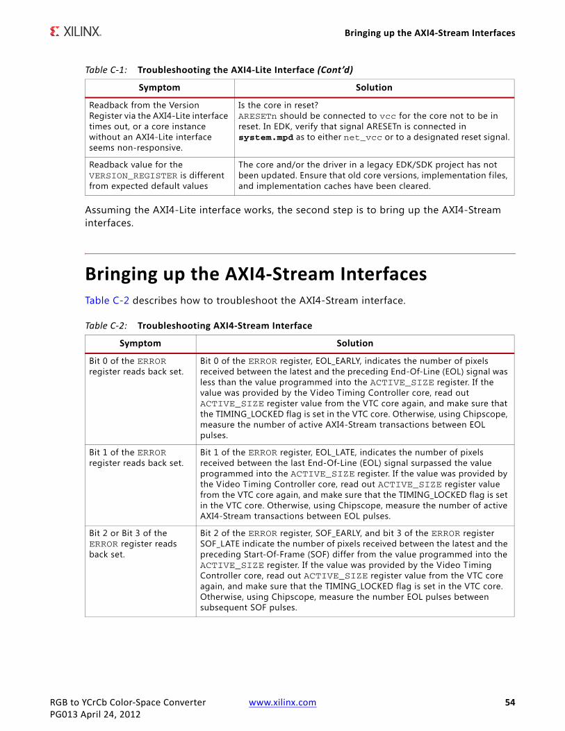
RGB to YCrCb Color-Space Converter www.xilinx.com 54PG013 April 24, 2012
Bringing up the AXI4-Stream Interfaces
Assuming the AXI4-Lite interface works, the second step is to bring up the AXI4-Stream interfaces.
Bringing up the AXI4-Stream InterfacesTable C-2 describes how to troubleshoot the AXI4-Stream interface.
Readback from the Version Register via the AXI4-Lite interface times out, or a core instance without an AXI4-Lite interface seems non-responsive.
Is the core in reset? ARESETn should be connected to vcc for the core not to be in reset. In EDK, verify that signal ARESETn is connected in system.mpd as to either net_vcc or to a designated reset signal.
Readback value for the VERSION_REGISTER is different from expected default values
The core and/or the driver in a legacy EDK/SDK project has not been updated. Ensure that old core versions, implementation files, and implementation caches have been cleared.
Table C-2: Troubleshooting AXI4-Stream Interface
Symptom Solution
Bit 0 of the ERROR register reads back set.
Bit 0 of the ERROR register, EOL_EARLY, indicates the number of pixels received between the latest and the preceding End-Of-Line (EOL) signal was less than the value programmed into the ACTIVE_SIZE register. If the value was provided by the Video Timing Controller core, read out ACTIVE_SIZE register value from the VTC core again, and make sure that the TIMING_LOCKED flag is set in the VTC core. Otherwise, using Chipscope, measure the number of active AXI4-Stream transactions between EOL pulses.
Bit 1 of the ERROR register reads back set.
Bit 1 of the ERROR register, EOL_LATE, indicates the number of pixels received between the last End-Of-Line (EOL) signal surpassed the value programmed into the ACTIVE_SIZE register. If the value was provided by the Video Timing Controller core, read out ACTIVE_SIZE register value from the VTC core again, and make sure that the TIMING_LOCKED flag is set in the VTC core. Otherwise, using Chipscope, measure the number of active AXI4-Stream transactions between EOL pulses.
Bit 2 or Bit 3 of the ERROR register reads back set.
Bit 2 of the ERROR register, SOF_EARLY, and bit 3 of the ERROR register SOF_LATE indicate the number of pixels received between the latest and the preceding Start-Of-Frame (SOF) differ from the value programmed into the ACTIVE_SIZE register. If the value was provided by the Video Timing Controller core, read out ACTIVE_SIZE register value from the VTC core again, and make sure that the TIMING_LOCKED flag is set in the VTC core. Otherwise, using Chipscope, measure the number EOL pulses between subsequent SOF pulses.
Table C-1: Troubleshooting the AXI4-Lite Interface (Cont’d)
Symptom Solution
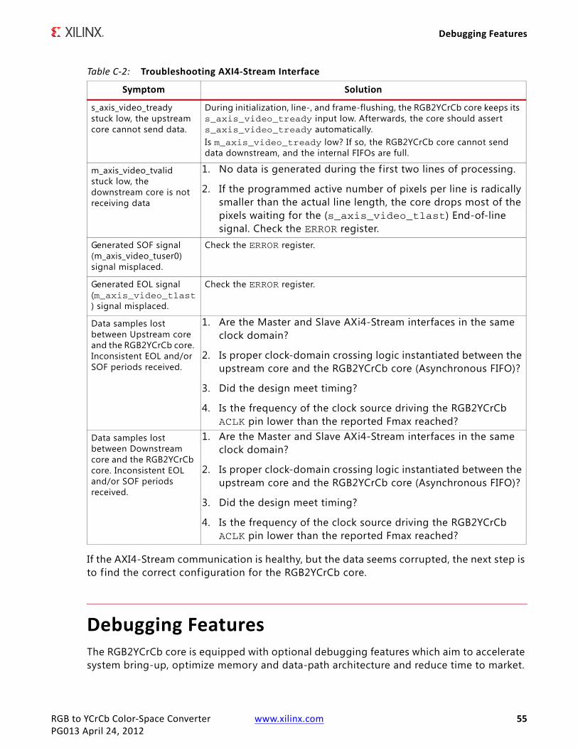
RGB to YCrCb Color-Space Converter www.xilinx.com 55PG013 April 24, 2012
Debugging Features
If the AXI4-Stream communication is healthy, but the data seems corrupted, the next step is to find the correct configuration for the RGB2YCrCb core.
Debugging FeaturesThe RGB2YCrCb core is equipped with optional debugging features which aim to accelerate system bring-up, optimize memory and data-path architecture and reduce time to market.
s_axis_video_tready stuck low, the upstream core cannot send data.
During initialization, line-, and frame-flushing, the RGB2YCrCb core keeps its s_axis_video_tready input low. Afterwards, the core should assert s_axis_video_tready automatically. Is m_axis_video_tready low? If so, the RGB2YCrCb core cannot send data downstream, and the internal FIFOs are full.
m_axis_video_tvalid stuck low, the downstream core is not receiving data
1. No data is generated during the f irst two lines of processing.
2. If the programmed active number of pixels per line is radically smaller than the actual line length, the core drops most of the pixels waiting for the (s_axis_video_tlast) End-of-line signal. Check the ERROR register.
Generated SOF signal (m_axis_video_tuser0) signal misplaced.
Check the ERROR register.
Generated EOL signal (m_axis_video_tlast) signal misplaced.
Check the ERROR register.
Data samples lost between Upstream core and the RGB2YCrCb core. Inconsistent EOL and/or SOF periods received.
1. Are the Master and Slave AXi4-Stream interfaces in the same clock domain?
2. Is proper clock-domain crossing logic instantiated between the upstream core and the RGB2YCrCb core (Asynchronous FIFO)?
3. Did the design meet timing?
4. Is the frequency of the clock source driving the RGB2YCrCb ACLK pin lower than the reported Fmax reached?
Data samples lost between Downstream core and the RGB2YCrCb core. Inconsistent EOL and/or SOF periods received.
1. Are the Master and Slave AXi4-Stream interfaces in the same clock domain?
2. Is proper clock-domain crossing logic instantiated between the upstream core and the RGB2YCrCb core (Asynchronous FIFO)?
3. Did the design meet timing?
4. Is the frequency of the clock source driving the RGB2YCrCb ACLK pin lower than the reported Fmax reached?
Table C-2: Troubleshooting AXI4-Stream Interface
Symptom Solution

RGB to YCrCb Color-Space Converter www.xilinx.com 56PG013 April 24, 2012
Debugging Features
The optional debug features can be turned on/off via the Include Debug Features checkbox on the GUI when an AXI4-Lite interface is present. Turning off debug features reduces the core Slice footprint.
Core Bypass OptionThe bypass option facilitates establishing a straight through connection between input (AXI4-Stream slave) and output (AXI4-Stream master) interfaces bypassing any processing functionality.
Flag BYPASS (bit 4 of the CONTROL register) can turn bypass on (1) or off, when the core instance Debugging Features were enabled at generation. Within the IP this switch controls multiplexers in the AXI4-Stream path.
In bypass mode the RGB2YCrCb core processing function is bypassed, and the core repeats AXI4-Stream input samples on its output. In bypass mode sensor samples are presented via the Green component output, while Red and Blue component outputs are set to zero.
Starting a system with all processing cores set to bypass, then by turning bypass off from the system input towards the system output allows verif ication of subsequent cores with known good stimuli.
Built in Test-Pattern GeneratorThe optional built-in test-pattern generator facilitates to temporarily feed the output AXI4-Stream master interface with a predefined pattern.
Flag TEST_PATTERN (bit 5 of the CONTROL register) can turn test-pattern generation on (1) or off, when the core instance Debugging Features were enabled at generation. Within the IP this switch controls multiplexers in the AXI4-Stream path, switching between the regular core processing output and the test-pattern generator. When enabled, a set of counters generate 256 scan-lines of color-bars, each color bar 64 pixels wide, repetitively cycling through Black, Red, Green, Yellow, Blue, Magenta, Cyan, and White colors till the end of each scan-line. After the Color-Bars segment, the rest of the frame is f illed with a monochrome horizontal and vertical ramp.
Starting a system with all processing cores set to test-pattern mode, then by turning test-pattern generation off from the system output towards the system input allows successive bring-up and parameterization of subsequent cores.
Throughput MonitorsThroughput monitors enable the user to monitor processing performance within the core. This information can be used to help debug frame-buffer bandwidth limitation issues, and if possible, allow video application software to balance memory pathways.

RGB to YCrCb Color-Space Converter www.xilinx.com 57PG013 April 24, 2012
Interfacing to Third-Party IP
Often times video systems, with multiport access to a shared external memory, have different processing islands. For example a pre-processing sub-system working in the input video clock domain may clean up, transform, and write a video stream, or multiple video streams, to memory. The processing sub-system may read the frames out, process, scale, encode, then write frames back to the frame buffer, in a separate processing clock domain. Finally, the output sub-system may format the data and read out frames locked to an external clock.
Typically, access to external memory using a multiport memory controller involves arbitration between competing streams. However, to maximize the throughput of the system, different memory ports may need different specific priorities. To fine tune the arbitration and dynamically balance frame rates, it is beneficial to have access to throughput information measured in different video data paths.
The SYSDEBUG0 (0x0014), or Frame Throughput Monitor, register indicates the number of frames processed since power-up or the last time the core was reset. The SYSDEBUG1 (0x0018), or Line Throughput Monitor, register indicates the number of lines processed since power-up or the last time the core was reset. The SYSDEBUG2 (0x001C), or Pixel Throughput Monitor, register indicates the number of pixels processed since power-up or the last time the core was reset.
Priorities of memory access points can be modified by the application software dynamically to equalize frame, or partial frame rates.
Interfacing to Third-Party IPTable C-3 describes how to troubleshoot third-party interfaces.
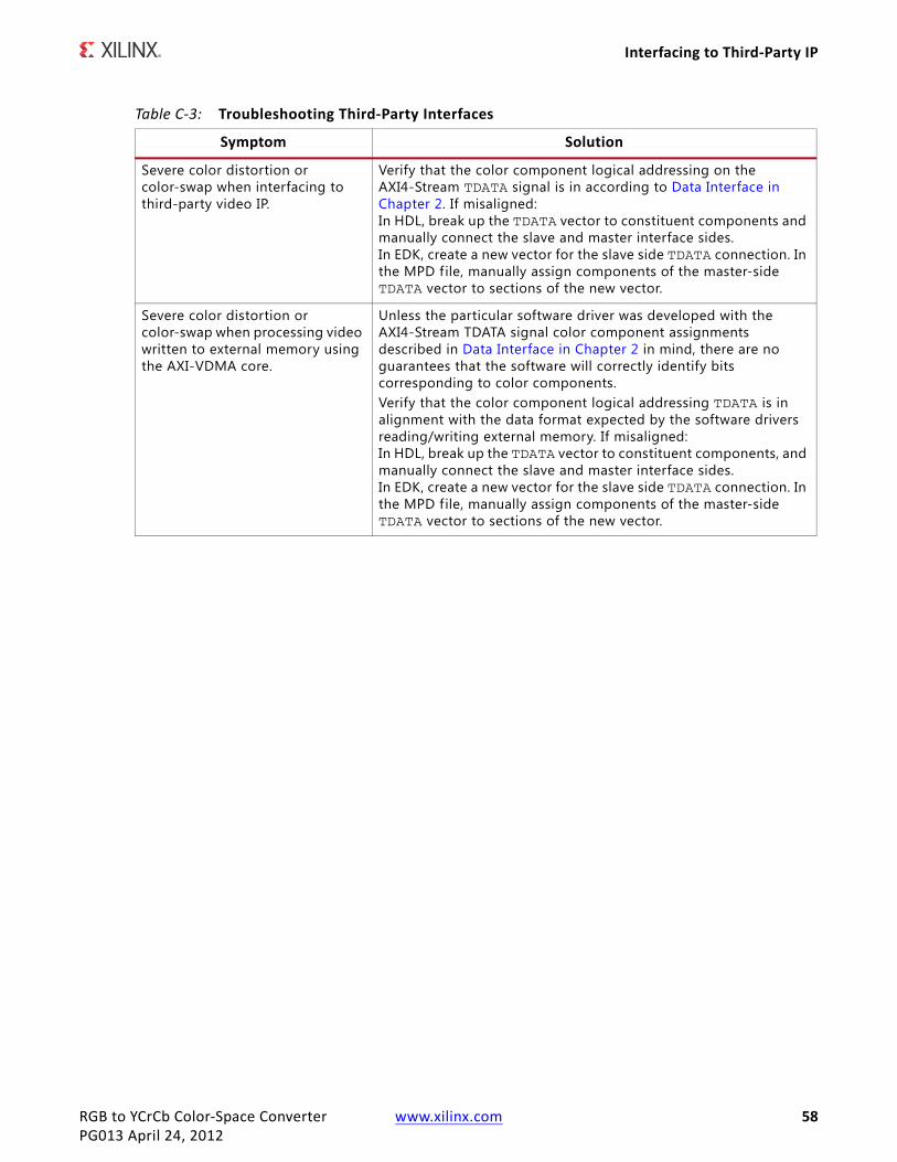
RGB to YCrCb Color-Space Converter www.xilinx.com 58PG013 April 24, 2012
Interfacing to Third-Party IP
Table C-3: Troubleshooting Third-Party Interfaces
Symptom Solution
Severe color distortion or color-swap when interfacing to third-party video IP.
Verify that the color component logical addressing on the AXI4-Stream TDATA signal is in according to Data Interface in Chapter 2. If misaligned: In HDL, break up the TDATA vector to constituent components and manually connect the slave and master interface sides. In EDK, create a new vector for the slave side TDATA connection. In the MPD file, manually assign components of the master-side TDATA vector to sections of the new vector.
Severe color distortion or color-swap when processing video written to external memory using the AXI-VDMA core.
Unless the particular software driver was developed with the AXI4-Stream TDATA signal color component assignments described in Data Interface in Chapter 2 in mind, there are no guarantees that the software will correctly identify bits corresponding to color components. Verify that the color component logical addressing TDATA is in alignment with the data format expected by the software drivers reading/writing external memory. If misaligned: In HDL, break up the TDATA vector to constituent components, and manually connect the slave and master interface sides. In EDK, create a new vector for the slave side TDATA connection. In the MPD file, manually assign components of the master-side TDATA vector to sections of the new vector.
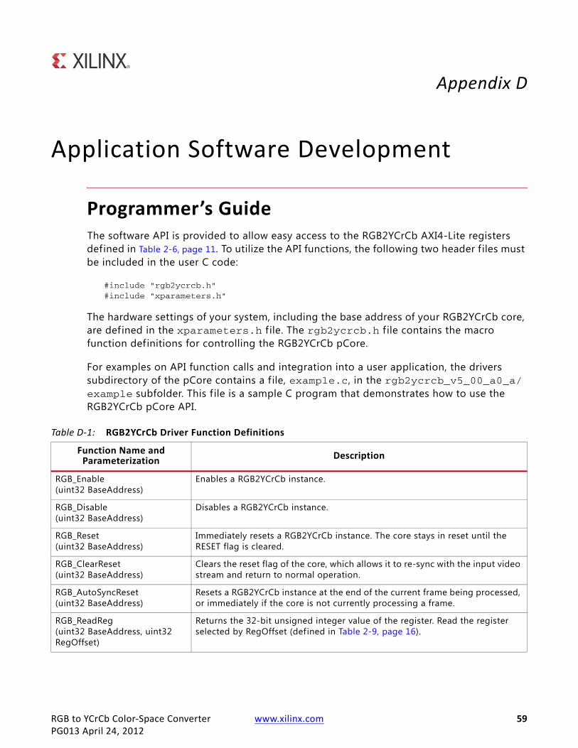
RGB to YCrCb Color-Space Converter www.xilinx.com 59PG013 April 24, 2012
Appendix D
Application Software Development
Programmer’s GuideThe software API is provided to allow easy access to the RGB2YCrCb AXI4-Lite registers defined in Table 2-6, page 11. To utilize the API functions, the following two header f iles must be included in the user C code:
#include "rgb2ycrcb.h"#include "xparameters.h"
The hardware settings of your system, including the base address of your RGB2YCrCb core, are defined in the xparameters.h f ile. The rgb2ycrcb.h f ile contains the macro function definitions for controlling the RGB2YCrCb pCore.
For examples on API function calls and integration into a user application, the drivers subdirectory of the pCore contains a file, example.c, in the rgb2ycrcb_v5_00_a0_a/example subfolder. This f ile is a sample C program that demonstrates how to use the RGB2YCrCb pCore API.
Table D-1: RGB2YCrCb Driver Function Definitions
Function Name and Parameterization Description
RGB_Enable(uint32 BaseAddress)
Enables a RGB2YCrCb instance.
RGB_Disable(uint32 BaseAddress)
Disables a RGB2YCrCb instance.
RGB_Reset(uint32 BaseAddress)
Immediately resets a RGB2YCrCb instance. The core stays in reset until the RESET flag is cleared.
RGB_ClearReset(uint32 BaseAddress)
Clears the reset flag of the core, which allows it to re-sync with the input video stream and return to normal operation.
RGB_AutoSyncReset(uint32 BaseAddress)
Resets a RGB2YCrCb instance at the end of the current frame being processed, or immediately if the core is not currently processing a frame.
RGB_ReadReg(uint32 BaseAddress, uint32 RegOffset)
Returns the 32-bit unsigned integer value of the register. Read the register selected by RegOffset (defined in Table 2-9, page 16).

RGB to YCrCb Color-Space Converter www.xilinx.com 60PG013 April 24, 2012
Programmer’s Guide
Software ResetSoftware reset reinitializes registers of the AXI4-Lite control interface to their initial value, resets FIFOs, forces m_axis_video_tvalid and s_axis_video_tready to 0. RGB_Reset() and RGB_AutoSyncReset () reset the core immediately if the core is not currently processing a frame. If the core is currently processing a frame calling RGB_Reset(), or setting bit 30 of the CONTROL register to 1 will cause image tearing. After calling RGB_Reset(), the core remains in reset until RGB_ClearReset() is called.
Calling RGB_AutoSyncReset() automates this reset process by waiting until the core f inishes processing the current frame, then asserting the reset signal internally, keeping the core in reset only for 32 ACLK cycles, then deasserting the signal automatically. After calling
RGB_WriteReg(uint32 BaseAddress, uint32 RegOffset, uint32 Data)
Write the register selected by RegOffset (defined in Table 2-9. Data is the 32-bit value to write to the register.
RGB_RegUpdateEnable(uint32 BaseAddress)
Enables copying double buffered registers at the beginning of the next frame. Refer to Double Buffering for more information.
RGB_RegUpdateDisable(uint32 BaseAddress)
Disables copying double buffered registers at the beginning of the next frame. Refer to Double Buffering for more information.
RGB_select_standard(int standard_sel, int input_range, int data_width, struct rgb_coef_inputs *coef_in)
Populates an rgb_coef_inputs structure with the values from the selected Video standardstandard_sel 0 = SD_ITU_601 1 = HD_ITU_709__1125_NTSC 2 = HD_ITU_709__1250_PAL 3 = YUVinput_range 0 = 16_to_240_for_TV, 1 = 16_to_235_for_Studio_Equipment 3 = 0_to_255_for_Computer_Graphics
RGB_coeff icient_translation(struct rgb_coef_inputs *coef_in, struct rgb_coef_outputs *coef_out)
Translates the rgb_coef_inputs structure into the rgb_coef_outputs structure that can be used to program the core's registers. The rgb_coef_inputs structure uses the same values as the core's GUIs. The rgb_coef_outputs structure uses the values that can be programmed into the core's registers.
void RGB_set_coeff icients(Xuint32 BaseAddress, struct rgb_coef_outputs *coef_out)
Writes the translated coeff icient values to the core's registers.
void RGB_get_coeff icients(Xuint32 BaseAddress, struct rgb_coef_outputs *coef_out)
Reads the translated coefficient values from the core's registers.
Table D-1: RGB2YCrCb Driver Function Definitions
Function Name and Parameterization Description
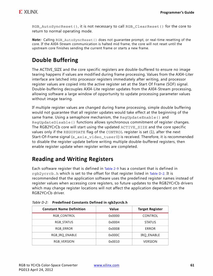
RGB to YCrCb Color-Space Converter www.xilinx.com 61PG013 April 24, 2012
Programmer’s Guide
RGB_AutoSyncReset(), it is not necessary to call RGB_ClearReset() for the core to return to normal operating mode.
Note: Calling RGB_AutoSyncReset() does not guarantee prompt, or real-time resetting of the core. If the AXI4-Stream communication is halted mid frame, the core will not reset until the upstream core f inishes sending the current frame or starts a new frame.
Double Buffering The ACTIVE_SIZE and the core specific registers are double-buffered to ensure no image tearing happens if values are modif ied during frame processing. Values from the AXI4-Liter interface are latched into processor registers immediately after writing, and processor register values are copied into the active register set at the Start Of Frame (SOF) signal. Double-buffering decouples AXI4-Lite register updates from the AXI4-Stream processing, allowing software a large window of opportunity to update processing parameter values without image tearing.
If multiple register values are changed during frame processing, simple double buffering would not guarantee that all register updates would take effect at the beginning of the same frame. Using a semaphore mechanism, the RegUpdateEnable() and RegUpdateDisable() functions allows synchronous commitment of register changes. The RGB2YCrCb core will start using the updated ACTIVE_SIZE and the core specif ic values only if the REGUPDATE flag of the CONTROL register is set (1), after the next Start-Of-Frame signal (s_axis_video_tuser0) is received. Therefore, it is recommended to disable the register update before writing multiple double-buffered registers, then enable register update when register writes are completed.
Reading and Writing RegistersEach software register that is defined in Table 2-9 has a constant that is defined in rgb2ycrcb.h which is set to the offset for that register listed in Table D-2. It is recommended that the application software uses the predefined register names instead of register values when accessing core registers, so future updates to the RGB2YCrCb drivers which may change register locations will not affect the application dependent on the RGB2YCrCb driver.
Table D-2: Predefined Constants Defined in rgb2ycrcb.h
Constant Name Definition Value Target Register
RGB_CONTROL 0x0000 CONTROL
RGB_STATUS 0x0004 STATUS
RGB_ERROR 0x0008 ERROR
RGB_IRQ_ENABLE 0x000C IRQ_ENABLE
RGB_VERSION 0x0010 VERSION

RGB to YCrCb Color-Space Converter www.xilinx.com 62PG013 April 24, 2012
Programmer’s Guide
RGB_SYSDEBUG0 0x0014 SYSDEBUG0
RGB_SYSDEBUG1 0x0018 SYSDEBUG1
RGB_SYSDEBUG2 0x001C SYSDEBUG2
RGB_ACTIVE_SIZE 0x0020 ACTIVE_SIZE
RGB_YMAX 0x100 YMAX
RGB_YMIN 0x104 YMIN
RGB_CBMAX 0x108 CBMAX
RGB_CBMIN 0x10C CBMIN
RGB_CRMAX 0x110 CRMAX
RGB_CRMIN 0x114 CRMIN
RGB_YOFFSET 0x118 YOFFSET
RGB_CBOFFSET 0x11C CBOFFSET
RGB_CROFFSET 0x120 CROFFSET
RGB_ACOEF 0x124 ACOEF
RGB_BCOEF 0x128 BCOEF
RGB_CCOEF 0x12C CCOEF
RGB_DCOEF 0x130 DCOEF
Table D-2: Predefined Constants Defined in rgb2ycrcb.h (Cont’d)
Constant Name Definition Value Target Register

RGB to YCrCb Color-Space Converter www.xilinx.com 63PG013 April 24, 2012
Appendix E
C-Model Reference
Installation and Directory StructureThis chapter contains information for installing the RGB to YCrCb Color-Space Converter C-Model, and describes the f ile contents and directory structure.
Software RequirementsThe RGB to YCrCb Color-Space Converter v5.00.a C-models were compiled and tested with the following software versions.
InstallationThe installation of the C-Model requires updates to the PATH variable, as described below.
Linux
Ensure that the directory in which the libIp_v_rgb2ycrcb_v5_00_a_bitacc_cmodel.so and libstlport.so.5.1 f iles are located is in your $LD_LIBRARY_PATH environment variable.
Table E-1: Supported Systems and Software Requirements
Platform C-Compiler
Linux 32-bit and 64-bit GCC 4.1.1
Windows 32-bit and 64-bit Microsoft Visual Studio 2005, Visual Studio 2008 (Visual C++ 8.0)

RGB to YCrCb Color-Space Converter www.xilinx.com 64PG013 April 24, 2012
Installation and Directory Structure
C-Model File ContentsUnzipping the v_rgb2ycrcb_v5_00_a_bitacc_model.zip file creates the following directory structures and files which are described inTable E-2.
Table E-2: C-Model Files
File Description
/lin Pre-compiled bit accurate ANSI C reference model for simulation on 32-bit Linux Platforms
libIp_v_rgb2ycrcb_v5_00_a_bitacc_cmodel.lib
RGB to YCrCb Color-Space Converter v5.00.a model shared object library (Linux platforms only)
libstlport.so.5.1 STL library, referenced by the RGB to YCrCb Color-Space Converter library (Linux platforms only)
run_bitacc_cmodel Pre-compiled bit accurate executable for simulation on 32-bit Linux Platforms
/lin64 Pre-compiled bit accurate ANSI C reference model for simulation on 64-bit Linux Platforms
libIp_v_rgb2ycrcb_v5_00_a_bitacc_cmodel.lib
RGB to YCrCb Color-Space Converter v5.00.a model shared object library (Linux platforms only)
libstlport.so.5.1 STL library, referenced by the RGB to YCrCb Color-Space Converter library (Linux platforms only)
run_bitacc_cmodel Pre-compiled bit accurate executable for simulation on 32-bit Linux Platforms
/nt Pre-compiled bit accurate ANSI C reference model for simulation on 32-bit Windows Platforms
libIp_v_rgb2ycrcb_v5_00_a_bitacc_cmodel.lib
Pre-compiled library file for win32 compilation
run_bitacc_cmodel.exe Pre-compiled bit accurate executable for simulation on 32-bit Windows Platforms
/nt64 Pre-compiled bit accurate ANSI C reference model for simulation on 64-bit Windows Platforms
libIp_v_rgb2ycrcb_v5_00_a_bitacc_cmodel.lib
Pre-compiled library file for win32 compilation
run_bitacc_cmodel.exe Pre-compiled bit accurate executable for simulation on 64-bit Windows Platforms
README.txt Release notes
pg013_v_rgb2ycrcb.pdf RGB to YCrCb Color-Space Converter Core Product Guide
v_rgb2ycrcb_v5_00_a_bitacc_cmodel.h Model header file
rgb_utils.h Header f ile declaring the RGB image / video container type and support functions
bmp_utils.h Header file declaring the bitmap (.bmp) image file I/O functions

RGB to YCrCb Color-Space Converter www.xilinx.com 65PG013 April 24, 2012
Using the C-Model
Using the C-ModelThe bit accurate C model is accessed through a set of functions and data structures that are declared in the v_rgb2ycrcb_v5_00_a_bitacc_cmodel.h f ile. Before using the model, the structures holding the inputs, generics and output of the RGB to YCrCb Color-Space Converter instance must be defined:
struct xilinx_ip_v_rgb2ycrcb_v5_00_a_generics generics;struct xilinx_ip_v_rgb2ycrcb_v5_00_a_inputs inputs;struct xilinx_ip_v_rgb2ycrcb_v5_00_a_outputs outputs;
The declaration of these structures is in the v_rgb2ycrcb_v5_00_a_bitacc_cmodel.h f ile. Table E-3 lists the generic parameters taken by the RGB to YCrCb Color-Space Converter v5.00.a IP core bit accurate model, as well as the default values.
video_utils.h Header f ile declaring the generalized image / video container type, I/O and support functions.
Test_stimuli.bmp 32x32 sample test image
run_bittacc_cmodel.c Example code calling the C-Model
Table E-2: C-Model Files (Cont’d)
File Description
Table E-3: Core Generic Parameters and Default Values
Generic Variable Type Default
Value Range Description
IWIDTH int 8 8,10,12,16 Input data width
OWIDTH int 8 8,10,12,16 Output width The OWIDTH must equal the IWIDTH.
ACOEF double 0.299 0.0 - 1.0 A Coefficient1 0.0 < ACOEFF + BCOEFF < 1.0
BCOEF double 0.114 0.0 - 1.0 B Coefficient1 0.0 < ACOEFF + BCOEFF < 1.0
CCOEF double 0.713 0.0 - 0.9 C Coefficient1
DCOEF double 0.564 0.0 - 0.9 D Coefficient1
YOFFSET int 16 0 –2OWIDTH-1 Offset for the Luminance Channel
CBOFFSET int 128 0 - 2OWIDTH-1 Offset for the Cb Chrominance Channel
CROFFSET int 128 0 - 2OWIDTH-1 Offset for the Cr Chrominance Channel
YMIN int 16 0 - 2OWIDTH-1 Clamping value for the Luminance Channel
CBMIN int 16 0 - 2OWIDTH-1 Clamping value for the Cb Chrominance Channel
CRMIN int 16 0 - 2OWIDTH-1 Clamping value for the Cr Chrominance Channel
YMAX int 240 0 - 2OWIDTH-1 Clipping value for the Luminance Channel

RGB to YCrCb Color-Space Converter www.xilinx.com 66PG013 April 24, 2012
Using the C-Model
Calling xilinx_ip_v_rgb2ycrcb_v5_00_a_get_default_generics(&generics) initializes the generics structure with the default value.
The inputs structure defines the actual input image. For the description of the input video structure, see Input and Output Video Structures.
Calling xilinx_ip_v_rgb2ycrcb_v5_00_a_get_default_inputs(&generics, &inputs) initializes the input video structure before it can be assigned an image or video sequence using the memory allocation or f ile I/O functions provided in the BMP, RGB or video utility functions.
Note: The video_in variable is not initialized to point to a valid image/video container, as the container size depends on the actual test image to be simulated. The initialization of the video_in structure is described in C Model Example Code.
After the inputs are defined, the model can be simulated by calling this function:
int xilinx_ip_v_rgb2ycrcb_v5_00_a_bitacc_simulate(struct xilinx_ip_v_rgb2ycrcb_v5_00_a_generics* generics,struct xilinx_ip_v_rgb2ycrcb_v5_00_a_inputs* inputs,struct xilinx_ip_v_rgb2ycrcb_v5_00_a_outputs* outputs).
Results are included in the outputs structure, which contains only one member, type video_struct. After the outputs are evaluated and saved, dynamically allocated memory for input and output video structures must be released by calling this function:
void xilinx_ip_v_rgb2ycrcb_v5_00_a_destroy(struct xilinx_ip_v_rgb2ycrcb_v5_00_a_inputs *input, struct xilinx_ip_v_rgb2ycrcb_v5_00_a_outputs *output).
Successful execution of all provided functions, except for the destroy function, return value 0. A non-zero error code indicates that problems occurred during function calls.
Input and Output Video StructuresInput images or video streams can be provided to the RGB to YCrCb Color-Space Converter v5.00.a reference model using the video_struct structure, defined in video_utils.h:
struct video_struct{ int frames, rows, cols, bits_per_component, mode; uint16*** data[5]; };
CBMAX int 240 0 - 2OWIDTH-1 Clipping value for the Cb Chrominance Channel
CRMAX int 240 0 - 2OWIDTH-1 Clipping value for the Cr Chrominance Channel
HAS_CLIP int 1 0,1 Determines if Clipping is performed on the output data
HAS_CLAMP
int 1 0,1 Determines if Clamping is performed on the output data
Table E-3: Core Generic Parameters and Default Values

RGB to YCrCb Color-Space Converter www.xilinx.com 67PG013 April 24, 2012
Using the C-Model
Table E-4: Member Variables of the Video Structure
Member Variable Designation
frames Number of video/image frames in the data structure.
rows Number of rows per frame. Pertaining to the image plane with the most rows and columns, such as the luminance channel for YUV data. Frame dimensions are assumed constant through all frames of the video stream. However different planes, such as y, u and v can have different dimensions.
cols Number of columns per frame. Pertaining to the image plane with the most rows and columns, such as the luminance channel for YUV data. Frame dimensions are assumed constant through all frames of the video stream. However different planes, such as y, u and v can have different dimensions.
bits_per_component Number of bits per color channel/component.All image planes are assumed to have the same color/component representation. Maximum number of bits per component is 16.
mode Contains information about the designation of data planes. Named constants to be assigned to mode are listed in Table E-5.
data Set of f ive pointers to three dimensional arrays containing data for image planes. Data is in 16-bit unsigned integer format accessed as data[plane][frame][row][col].
Table E-5: Named Video Modes with Corresponding Planes and Representations1
Mode Planes Video Representation
FORMAT_MONO 1 Monochrome – Luminance only
FORMAT_RGB 3 RGB image/video data
FORMAT_C444 3 444 YUV, or YCrCb image/video data
FORMAT_C422 3 422 format YUV video, (u, v chrominance channels horizontally sub-sampled)
FORMAT_C420 3 420 format YUV video, ( u, v sub-sampled both horizontally and vertically )
FORMAT_MONO_M 3 Monochrome (Luminance) video with Motion
FORMAT_RGBA 4 RGB image/video data with alpha (transparency) channel
FORMAT_C420_M 5 420 YUV video with Motion
FORMAT_C422_M 5 422 YUV video with Motion
FORMAT_C444_M 5 444 YUV video with Motion
FORMAT_RGBM 5 RGB video with Motion
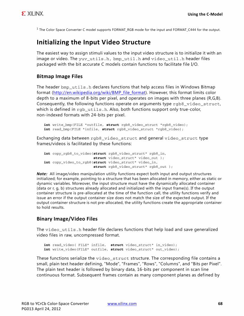
RGB to YCrCb Color-Space Converter www.xilinx.com 68PG013 April 24, 2012
Using the C-Model
1 The Color Space Converter C model supports FORMAT_RGB mode for the input and FORMAT_C444 for the output.
Initializing the Input Video StructureThe easiest way to assign stimuli values to the input video structure is to initialize it with an image or video. The yuv_utils.h, bmp_util.h and video_util.h header f iles packaged with the bit accurate C models contain functions to facilitate f ile I/O.
Bitmap Image Files
The header bmp_utils.h declares functions that help access files in Windows Bitmap format (http://en.wikipedia.org/wiki/BMP_file_format). However, this format limits color depth to a maximum of 8-bits per pixel, and operates on images with three planes (R,G,B). Consequently, the following functions operate on arguments type rgb8_video_struct, which is defined in rgb_utils.h. Also, both functions support only true-color, non-indexed formats with 24-bits per pixel.
int write_bmp(FILE *outfile, struct rgb8_video_struct *rgb8_video);int read_bmp(FILE *infile, struct rgb8_video_struct *rgb8_video);
Exchanging data between rgb8_video_struct and general video_struct type frames/videos is facilitated by these functions:
int copy_rgb8_to_video(struct rgb8_video_struct* rgb8_in, struct video_struct* video_out );
int copy_video_to_rgb8(struct video_struct* video_in, struct rgb8_video_struct* rgb8_out );
Note: All image/video manipulation utility functions expect both input and output structures initialized; for example, pointing to a structure that has been allocated in memory, either as static or dynamic variables. Moreover, the input structure must have the dynamically allocated container (data or r, g, b) structures already allocated and initialized with the input frame(s). If the output container structure is pre-allocated at the time of the function call, the utility functions verify and issue an error if the output container size does not match the size of the expected output. If the output container structure is not pre-allocated, the utility functions create the appropriate container to hold results.
Binary Image/Video Files
The video_utils.h header f ile declares functions that help load and save generalized video f iles in raw, uncompressed format.
int read_video( FILE* infile, struct video_struct* in_video);int write_video(FILE* outfile, struct video_struct* out_video);
These functions serialize the video_struct structure. The corresponding file contains a small, plain text header defining, "Mode", "Frames", "Rows", "Columns", and "Bits per Pixel". The plain text header is followed by binary data, 16-bits per component in scan line continuous format. Subsequent frames contain as many component planes as defined by
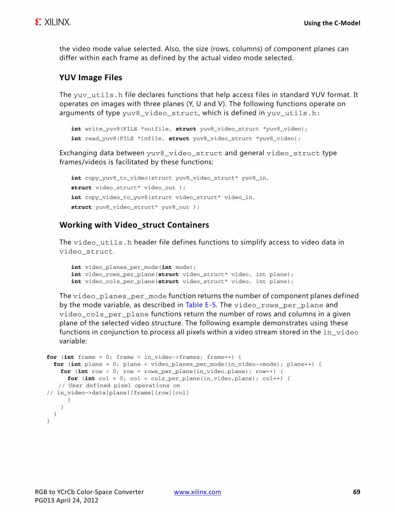
RGB to YCrCb Color-Space Converter www.xilinx.com 69PG013 April 24, 2012
Using the C-Model
the video mode value selected. Also, the size (rows, columns) of component planes can differ within each frame as defined by the actual video mode selected.
YUV Image Files
The yuv_utils.h f ile declares functions that help access f iles in standard YUV format. It operates on images with three planes (Y, U and V). The following functions operate on arguments of type yuv8_video_struct, which is defined in yuv_utils.h:
int write_yuv8(FILE *outfile, struct yuv8_video_struct *yuv8_video);
int read_yuv8(FILE *infile, struct yuv8_video_struct *yuv8_video);
Exchanging data between yuv8_video_struct and general video_struct type frames/videos is facilitated by these functions:
int copy_yuv8_to_video(struct yuv8_video_struct* yuv8_in,
struct video_struct* video_out );
int copy_video_to_yuv8(struct video_struct* video_in,
struct yuv8_video_struct* yuv8_out );
Working with Video_struct Containers
The video_utils.h header f ile defines functions to simplify access to video data in video_struct.
int video_planes_per_mode(int mode);int video_rows_per_plane(struct video_struct* video, int plane);int video_cols_per_plane(struct video_struct* video, int plane);
The video_planes_per_mode function returns the number of component planes defined by the mode variable, as described in Table E-5. The video_rows_per_plane and video_cols_per_plane functions return the number of rows and columns in a given plane of the selected video structure. The following example demonstrates using these functions in conjunction to process all pixels within a video stream stored in the in_video variable:
for (int frame = 0; frame < in_video->frames; frame++) { for (int plane = 0; plane < video_planes_per_mode(in_video->mode); plane++) { for (int row = 0; row < rows_per_plane(in_video,plane); row++) { for (int col = 0; col < cols_per_plane(in_video,plane); col++) {
// User defined pixel operations on // in_video->data[plane][frame][row][col] } } }}

RGB to YCrCb Color-Space Converter www.xilinx.com 70PG013 April 24, 2012
Compiling with the RGB to YCrCb C-Model
C Model Example CodeAn example C f ile, run_bitacc_cmodel.c, is provided to demonstrate the steps required to run the model. After following the compilation instructions, run the example executable. The executable takes the path/name of the input f ile and the path of the output as parameters. If invoked with insufficient parameters, this help message is issued:
Usage:run_bitacc_cmodel in_file out_path
in_file : path/name of the input file (24-bit RGB BMP file)
out_path : path to to the output files
The C model demonstrator run_bitacc_cmodel.c also generates stimuli and results text f iles which in turn can be processed by the example Verilog test-bench.
Compiling with the RGB to YCrCb C-Model
Linux (32- and 64-bit)To compile the example code, f irst ensure that the directory in which the files libIp_v_rgb2ycrcb_v5_00_a_bitacc_cmodel.so and libstlport.so.5.1 are located is present in your $LD_LIBRARY_PATH environment variable. These shared libraries are referenced during the compilation and linking process. Then cd into the directory where the header files, library f iles and run_bitacc_cmodel.c were unpacked. The libraries and header files are referenced during the compilation and linking process.
Place the header f ile and C source f ile in a single directory. Then in that directory, compile using the GNU C Compiler:
gcc -m32 -x c++ ../run_bitacc_cmodel.c ../gen_stim.c -o run_bitacc_cmodel -L. -lIp_v_rgb2ycrcb_v5_00_a_bitacc_cmodel -Wl,-rpath,.
gcc -m64 -x c++ ../run_bitacc_cmodel.c ../gen_stim.c -o run_bitacc_cmodel -L. -lIp_v_rgb2ycrcb_v5_00_a_bitacc_cmodel -Wl,-rpath,.
Windows (32- and 64-bit)Precompiled library v_rgb2ycrcb_v5_00_a_bitacc_cmodel.dll, and top level demonstration code run_bitacc_cmodel.c should be compiled with an ANSI C compliant compiler under Windows. Here an example is presented using Microsoft Visual Studio.
In Visual Studio create a new, empty Windows Console Application project. As existing items, add:
• The llibIpv_rgb2ycrcb_v5_00_a_bitacc_cmodel.dll f ile to the "Resource Files" folder of the project

RGB to YCrCb Color-Space Converter www.xilinx.com 71PG013 April 24, 2012
Compiling with the RGB to YCrCb C-Model
• The run_bitacc_cmodel.c and gen_stim.c f iles to the "Source Files" folder of the project
• The v_rgb2ycrcb_v5_00_a_bitacc_cmodel.h header f iles to "Header Files" folder of the project (optional)
After the project has been created and populated, it needs to be compiled and linked (built) to create a win32 executable. To perform the build step, choose Build Solution from the Build menu. An executable matching the project name has been created either in the Debug or Release subdirectories under the project location based on whether Debug or Release has been selected in the Configuration Manager under the Build menu.

RGB to YCrCb Color-Space Converter www.xilinx.com 72PG013 April 24, 2012
Appendix F
Additional Resources
Xilinx ResourcesFor support resources such as Answers, Documentation, Downloads, and Forums, see the Xilinx Support website at:
http://www.xilinx.com/support.
For a glossary of technical terms used in Xilinx documentation, see:
http://www.xilinx.com/support/documentation/sw_manuals/glossary.pdf.
For a comprehensive listing of Video and Imaging application notes, white papers, reference designs and related IP cores, see the Video and Imaging Resources page at:
http://www.xilinx.com/esp/video/refdes_listing.htm#ref_des.
Solution CentersSee the Xilinx Solution Centers for support on devices, software tools, and intellectual property at all stages of the design cycle. Topics include design assistance, advisories, and troubleshooting tips.

RGB to YCrCb Color-Space Converter www.xilinx.com 73PG013 April 24, 2012
References
ReferencesThese documents provide supplemental material useful with this user guide:
1. UG761 AXI Reference Guide
2. Jack, Keith. 2004. Video Demystified, 4th Edition. Burlington, MA: Newnes: pp 15-19.
3. Poynton, Charles. 2003. Digital Video and HDTV. San Francisco: Morgan Kaufmann: pp 302 - 321.
4. ITU Recommendation BT.601-5, International Telecommunication Union, 1995.
5. ITU Recommendation BT.709-5, International Telecommunication Union, 2002.
6. Proakis, John G., and Dimitris G. Manolakis. Digital Signal Processing, 3rd edition. Upper Saddle River, NJ: Prentice Hall: pp 755-756.
7. Sullivan, Gary. 2003. Approximate theoretical analysis of RGB to YCbCr to RGB conversion error. Presented for Joint Video Team (JVT) of ISO/IEC MPEG & ITU-T VCEG (ISO/IEC JTC1/SC29/WG11 and ITU-T SG16 Q.6), July 22-24, in Trondheim, Norway.
Technical SupportXilinx provides technical support at www.xilinx.com/support for this LogiCORE™ IP product when used as described in the product documentation. Xilinx cannot guarantee timing, functionality, or support of product if implemented in devices that are not defined in the documentation, if customized beyond that allowed in the product documentation, or if changes are made to any section of the design labeled DO NOT MODIFY.
See the IP Release Notes Guide (XTP025) for more information on this core. For each core, there is a master Answer Record that contains the Release Notes and Known Issues list for the core being used. The following information is listed for each version of the core:
• New Features
• Resolved Issues
• Known Issues
RGB to YCrCb Color-Space Converter www.xilinx.com 74PG013 April 24, 2012
Ordering Information
Ordering InformationThe RGB to YCrCb Color-Space Converter v5.00.a core is provided under the Xilinx Core License Agreement and can be generated using the Xilinx® CORE Generator™ system. The CORE Generator system is shipped with Xilinx ISE® Design Suite software.
Contact your local Xilinx sales representative for pricing and availability of additional Xilinx LogiCORE IP modules and software. Information about additional Xilinx LogiCORE IP modules is available on the Xilinx IP Center.
Revision HistoryThe following table shows the revision history for this document.
Notice of DisclaimerThe information disclosed to you hereunder (the “Materials”) is provided solely for the selection and use of Xilinx products. To the maximum extent permitted by applicable law: (1) Materials are made available “AS IS” and with all faults, Xilinx hereby DISCLAIMS ALL WARRANTIES AND CONDITIONS, EXPRESS, IMPLIED, OR STATUTORY, INCLUDING BUT NOT LIMITED TO WARRANTIES OF MERCHANTABILITY, NON-INFRINGEMENT, OR FITNESS FOR ANY PARTICULAR PURPOSE; and (2) Xilinx shall not be liable (whether in contract or tort, including negligence, or under any other theory of liability) for any loss or damage of any kind or nature related to, arising under, or in connection with, the Materials (including your use of the Materials), including for any direct, indirect, special, incidental, or consequential loss or damage (including loss of data, profits, goodwill, or any type of loss or damage suffered as a result of any action brought by a third party) even if such damage or loss was reasonably foreseeable or Xilinx had been advised of the possibility of the same. Xilinx assumes no obligation to correct any errors contained in the Materials or to notify you of updates to the Materials or to product specifications. You may not reproduce, modify, distribute, or publicly display the Materials without prior written consent. Certain products are subject to the terms and conditions of the Limited Warranties which can be viewed at http://www.xilinx.com/warranty.htm; IP cores may be subject to warranty and support terms contained in a license issued to you by Xilinx. Xilinx products are not designed or intended to be fail-safe or for use in any application requiring fail-safe performance; you assume sole risk and liability for use of Xilinx products in Critical Applications: http://www.xilinx.com/warranty.htm#critapps.© Copyright 2011–2012 Xilinx, Inc. Xilinx, the Xilinx logo, Artix, ISE, Kintex, Spartan, Virtex, Zynq, and other designated brands included herein are trademarks of Xilinx in the United States and other countries. All other trademarks are the property of their respective owners.
Date Version Revision10/19/2011 1.0 Initial Xilinx release of Product Guide, replacing DS657 and UG834.
4/24/2012 2.0 Updated for core version. Added Zynq-7000 devices, added AXI4-Stream interfaces, deprecated GPP interface.