Log ASCII Standard Document #1 – File Structures
44
Log ASCII Standard Document #1 – File Structures Kenneth Heslop - Oakrock Ltd., Calgary (Committee Chairman) Jim Karst - Schlumberger GeoQuest, Calgary Stephen Prensky - SPE, Consultant, Silver Spring, MD Dennis Schmitt - Texaco Upstream Technology, Houston Release 3.00 – June 6, 2000 LAS 3.0
Transcript of Log ASCII Standard Document #1 – File Structures

Log ASCII StandardDocument #1 – File Structures
Kenneth Heslop - Oakrock Ltd., Calgary (Committee Chairman)Jim Karst - Schlumberger GeoQuest, Calgary
Stephen Prensky - SPE, Consultant, Silver Spring, MDDennis Schmitt - Texaco Upstream Technology, Houston
Release 3.00 – June 6, 2000
LAS 3.0

LAS 3.0 File Structure Specifications -- Page # 2
Table of Contents
LAS Ver 3.0 Discussion 4
What’s new in LAS Ver 3.0 5
Conventions Used in this Document. 6
Major Components of a LAS Ver 3.0 File 7
Primary Section Types 7Parameter Data Sections 7Column Definition Sections 7Column Data Sections 7User Defined Sections 7
Lines Within Sections 7Parameter Data Lines 7Column Definition Lines 8Column Data Lines 8
Structure Details 9
Sections 9
Lines within Sections 9Section Title Lines 9Parameter Data Lines 10Column Definition Lines 11Column Data Lines 11
Individual Section Descriptions 13Required sections 13
~Version section 13Required Contents (All files) 13Details Specific to the ~Version section 13
~Well section 14Required Contents (All files) 14Details Specific to the ~Well section 15
Data Section Sets 17
Log Data sections 17Core Data sections 18Inclinometry Data sections 19Drilling Data sections 20Tops Data sections 21Test Data sections 22
LAS 3.0 Data Formats 23
Floating Point 23Integer 23String 23Exponential 24Date and Time 24Degree Minute Seconds 24
Three Dimension Data Arrays in Column Data sections 25
Section Title Arrays 27
Parameter Data Line Arrays 27
Associations in LAS 3.0 28
Example 1. Storing Multiple Runs 28Example 2. Column Data Channel Matrix Identification 29

LAS 3.0 File Structure Specifications -- Page # 3
Example 3. Parameter Zoning 29Column Data and Column Definition Section Associations 30
Adding User Defined Data and Sections 31
Appendix I Example LAS Ver 3.0 file 32Appendix II LAS Ver 3.0 Restricted Characters and Words 36
Characters 36Section Titles 37Parameter and Definition section Mnemonics 37
Appendix III Definitions 39Appendix IV Termination Issues 41Appendix V Real Time Data Acquisition 42Appendix VI LAS Certify 3.0 43

LAS 3.0 File Structure Specifications -- Page # 4
LAS Version 3.0 Discussion
The LAS format began with the desire for a simple format to exchange well log data. Theworld-wide acceptance of LAS proved the need for such a format. As users embraced theconcept and the format, many new applications of the concept were attempted. As datausers, we have all been tempted to put more data into our LAS files than the format wasoriginally designed to handle. This led to the realization that LAS needed to expand.
LAS 3.0 was originally proposed as an update to LAS 2.0, with just minor changes tohandle more well log data, such as multiple logging runs. But, like a ball rolling down ahill, the process quickly gained speed. What we are now presenting is a major redesignof the LAS format. We have maintained the founding principles of LAS, and those usingLAS 3.0 for log data alone will find that the format is much the same as previousversions. However, those wishing to use LAS 3.0 for other data types will find in thisformat the expanded flexibility to accurately and completely describe their data.
Originally LAS was designed around a collection of file “sections”. Each section beganwith a title line, and that title line was marked with a tilde (“~”) at the beginning of theline. This design has been maintained, and we have added several new sections, plusadded the rules for adding user-defined sections.
The standard will be released in two major parts. This first part will describe the fileSTRUCTURES, including those defined to hold the new data types, and the details of howto build a LAS ver 3.0 file.
The next part of the LAS 3.0 release will describe specific CONTENT requirements. Thesecontent requirements will describe the exact sections, parameters, and channels that willsatisfy the specific needs of each group or organization that wishes to define a LAS 3.0content requirements.
To introduce the new structure concepts, remember that in previous versions of LAS thefollowing sections were required: ~Version, ~Well, ~Curve and ~ASCII. The ~Versionsection contains only data related to the LAS file. This section is still required in LAS 3.0,and now has additional options added. The ~Well section contains all data that iscommon to every data set related to that specific well, including the well identificationand location. This section has been maintained and expanded.
The remaining sections in an LAS file will be defined by the data set or sets beingincluded. In general terms they will follow the pattern of a Parameter section, Definitionsection, and a Data section for each data set. This is consistent with the historical~Parameter, ~Curve and ~ASCII sections used for log data. While these section nameshave been maintained for log data, the equivalent sections for new data sets will followthis new naming convention:
~Section_Parameter, ~Section_Definition, and ~Section_Data.
Some data sets will require all three of these section, others may only require aParameter section, or a combination of Definition and Data sections.
A LAS 3.0 file might contain just one data set, such as logs or core, or it could contain anumber of data sets. Whichever option is chosen, there must only be one ~Versionsection, and one ~Well section. These sections must also be the first two sections in thefile, and in this order. After that, each data set should appear as a set. For example, the~Parameter, ~Curve, and ~ASCII sections must appear together. Likewise~Core_Parameter, ~Core_Definition, and ~Core_Data must appear together.
The future has been designed into the new version of LAS. Using the following two datamodels, provision has been made to allow users to define new sections as the needarises. These new sections should fit either of the following cases:
1) Self-contained Sections, such as the ~Well Information and ~Parameter sections.(Note: In most cases the ~Parameter sections are related to other data sections.)Following this example, the new section would look something like this:
~NewSection_Parameter

LAS 3.0 File Structure Specifications -- Page # 5
Name .Unit Data : Description {F} | Association
2) Data Sections with related Definition and optional Parameter sections. These sectionswill follow the ~Parameter, ~Curve, ~ASCII model where ~Parameters contains headerinformation related to the log data, ~Curve contains the definitions of the log curvespresent, and ~ASCII contains an indexed table of log digits.
~NewSection_Parameter
Para1 .Unit Data : Description {F} | Association
~NewSection_Definition
Index .Unit Data : Description {F} | Association Chan1 .Unit Data : Description {F} | Association
~NewSection_Data | NewSection_Definition
1234.00,5678.001234.25,6789.001234.50,7890.00
The Parameter sections are optional, and should only be used for data that is directlyrelevant to the type of data intended for that section.
In all cases, user-defined sections must follow the same structure rules set out for thedefined sections in this document.
What’s new in LAS Ver 3.0
This is a short list of the new features in Ver 3.0
1. New Data types. (Core, Drilling etc).2. "Structure" rules separated from "Content" rules.3. New delimiters and structures.4. Comma Tab and Space delimited data.5. Handles 1D, 2D and 3D arrays6. Supports Multiple Runs.7. Parameter Zoning.8. Floating point, string, integer, Date and Time formats supported.9. Addition of User defined data is easy10. WRAP YES has been dropped.11. ~Other section has been dropped.
LAS 3.0 File Structure Specifications -- Page # 6
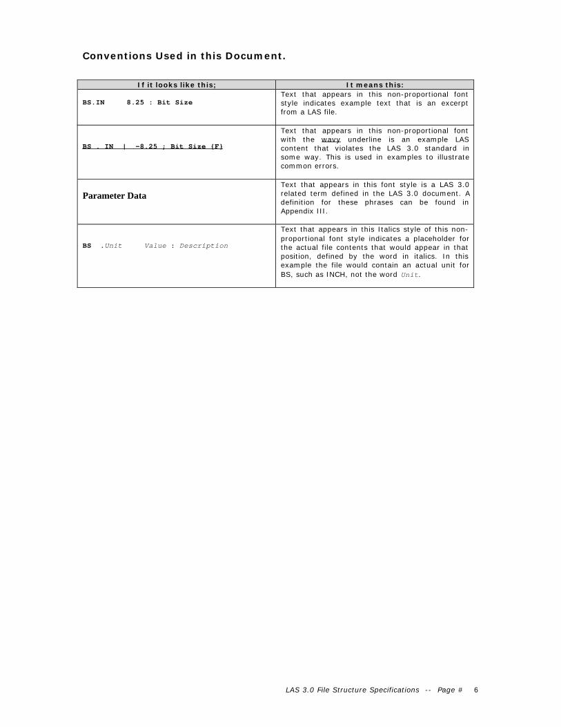
Conventions Used in this Document.
If it looks like this; It means this:
BS.IN 8.25 : Bit SizeText that appears in this non-proportional fontstyle indicates example text that is an excerptfrom a LAS file.
BS . IN | -8.25 ; Bit Size {F}
Text that appears in this non-proportional fontwith the wavy underline is an example LAScontent that violates the LAS 3.0 standard insome way. This is used in examples to illustratecommon errors.
Parameter Data
Text that appears in this font style is a LAS 3.0related term defined in the LAS 3.0 document. Adefinition for these phrases can be found inAppendix III.
BS .Unit Value : Description
Text that appears in this Italics style of this non-proportional font style indicates a placeholder forthe actual file contents that would appear in thatposition, defined by the word in italics. In thisexample the file would contain an actual unit forBS, such as INCH, not the word Unit.
LAS 3.0 File Structure Specifications -- Page # 7
Major Components of a LAS Ver 3.0 File
LAS Files are divided into logical sections. Sections are recognized by lines that beginwith the ~ (tilde, ASCII 126) character. These section defining lines are called SectionTitle lines. Specific sections are recognized by their names, which follow the ~(tilde)character. The entire word following the ~ is the section name, not just the firstcharacter after the ~.
Sections contain lines where data is described and/or stored. There are several types ofsections and several types of lines within sections.
The LAS 3.0 standard defines which combinations of sections must exist in LAS files, andin which order. For example, the ~Version and ~Well section must exist in that order inall Ver 3.0 LAS files.
As in LAS version 2.0, only one well will be described within a single file.
Data is stored as one, two or three dimensional arrays. The data are usually indexed todepth or time, but may be presented as discrete measurements if required.
Data is grouped by type into related sections, as they relate to the well in which thatdata was acquired. Types include depth and time indexed Logging, Core, Inclinometry,Drilling, Formation tops, test data, user defined types, etc.
Primary Section Types
Parameter Data Sections
Contains any number of Parameter Data lines (see below). Intended to hold Onedimensional data that relates in general to one of the data types described.
Column Definition Sections
Contains any number of Column Definition lines (see below). Intended to hold detaileddescriptions (name, unit, etc) of each 2D or 3D channels stored in a Column Datasection. There is always a matching Column Data section.
Column Data Sections
Contains any number of Column Data lines (see below). Intended to hold 2D and 3Dindexed and non-indexed channels. There is always a matching Column Definitionsection that fully describes each channel. There may also be a matching ParameterData section that holds related parameters.
User Defined Sections
Other types of sections can be defined as the user needs. Always use the above threeprimary types whenever possible. See the section on Adding User Defined Data foradditional details.
Lines Types Within Sections
Parameter Data Lines
Appear in Parameter Data sections.
Each Parameter Data line contains a one dimensional data item consisting of (usuallybut not restricted to) one or two elements. Each line also contains a full description ofthat data.
Some Parameter Data lines are required in certain sections. Some of these requiredParameter Data lines must also contain data, while other do not. Later sectionsdiscussing specific sections will state specific requirements.

LAS 3.0 File Structure Specifications -- Page # 8
Note: Required implies the Parameter Data line for each listed item must exist,consisting of the Mnemonic, unit (if applicable), and description. The Value field foreach required Parameter Data line does not have to filled in for LAS compliance. Theexception to this rule It is strongly recommended that
Column Definition Lines
Appear only in Column Definition sections.
Although structurally identical to a Parameter Data lines (see above), each ColumnDefinition line is used to describe each matching (by order) channel contained in thematching Column Data section. The name, unit, log code, description and format (if
used) contained in each Column Definition line fully describe the channel it refers to.
Column Data Lines
Appear only in Column Data sections.
Each line contains a series of delimited data values. The delimiting character is definedby the value of the DLM parameter in the ~Version section. Descriptions of each dataare contained in the matching Column Definition section.

LAS 3.0 File Structure Specifications -- Page # 9
Structure Details
The details of the sections and the lines within the sections are discussed.
Sections
The ~Version and ~Well sections must appear in every LAS 3.0 file as the first andsecond sections respectively.
Other sections are grouped by data type. Each group consists of two or three sections; aParameter Data section (optional for all but Log data), a Column Definition section,
and a Column Data section, in that order.
For example, core analysis data would have the following three sections:
~Core_Parameter~Core_Definition~Core_Data.
At least one group or data type of either the defined LAS 3.0 data types or a userdefined type must exist in every LAS 3.0 file.
The Column Definition and the Column Data sections for each data type are matchedsets and must both appear in that order. The corresponding Parameter Data section isoptional (except for Log data), but if used must appear before it's correspondingColumn Definition Section.
LAS 3.0 defines six specific well related data types and their root Section Title names.They are:
~Ascii or ~Log~Core~Inclinometry~Drilling~Tops~Test
Additional data types can be defined by the user and content rules discussed elsewherein the document may define other section titles.
Stand alone user defined Parameter Data sections can be included. Care must be takento use standalone Parameter Data sections only when the data contained does not fitinto any of the other defined data types.
When used, the section order of each set of the three sections for each data type mustbe Parameter, Definition, then Data.
Blank lines and comment lines can appear within Column Data sections, but can onlyappear BEFORE the first Column Data line of that section, or after the LAST ColumnData line of that section.
The names of each channel can optionally appear above each channel as a comment lineimmediately before, after or on the section title line of that section if space allows.
Note: Do not use the ~Other section recognized by LAS ver 2.0. It is no longer allowedin LAS 3.0. Any data that can be stored in such a section, must now be stored properlyin a user defined Parameter Data or Column Data section.
Lines Within Sections
Section Title Lines
First non-space character of the line must the ~ (tilde, ASCII 126) character.
The identifying Section Title is all characters from the first character after the ~ (tilde)until the next space, the next | (bar) character, or the end of that line.
LAS 3.0 File Structure Specifications -- Page # 10
Parameter Data section titles must be named by appending the suffix _Parameter tothe root Section Title such as ~Core_Parameter.
Column Definition section titles must be named by appending the suffix _Definitionto the root Section Title such as ~Core_Definition.
Column Data section titles must be named by appending the suffix _Data to the root
Section Title such as ~Core_Data.
Sections that are exceptions to the required suffix additions are the ~Parameter,~Curve and ~ASCII sections, which implies logging data.
The Column Data Section Title line must include an association to its matching
Column Definition section.
Do this by first placing a | (bar, ASCII 124) character after the Section Title, thenadding the full matching Column Definition section title (without the ~ tilde), such as;
~Core_Data | Core_Definition
This gives a reliable way of knowing which Column Definition section belongs with thisColumn Data section.
Note: No other section title lines other than a Data Section title line may use theassociation delimiter (|) followed by other section titles.
The Section Title line must contain at least the ~ (tilde) and a section title.The character immediately after the ~ (tilde) must not be a space, i.e. the section titlemust begin immediately after the ~ (tilde).
If the bar character and matching Column Definition section title are included, thenthat matching Column Definition section must exist in the LAS file.
Any number of spaces can separate the section title and | (bar) delimiter and thematching Column Definition section title.
Parameter Data Lines
Each Parameter Data line consists of at least four, and up to six delimited fields. Eachfield has a defined name. Some fields may only contain spaces if not needed (such asUnit).
MNEM.UNIT VALUE : DESCRIPTION {Format} | Assoc1,Assoc2 …
Delimiting characters and the following rules are used to separate the fields. Fulldescriptions of the delimiters can be found in Appendix II.
Each section should have the first period and last colon, and all other delimitingcharacters and fields aligned for each of reading, but this is not a requirement, nor ishaving the same alignment of the delimiters in all sections.
Note: Do not use TAB characters on a Parameter Data line in an attempt to space outthe items. Use Spaces only for this purpose. Tabs are reserved for use as delimitingcharacters, and may only be used on Parameter Data lines as delimiters betweenmultiple Value field data items or to delimit Association Parameters.
MNEMONIC (MNEM)
Any length >0, but must not contain periods, colons, embedded spaces, tabs, { }. [ ], |(bar) characters, leading or trailing spaces are ignored. It ends at (but does not include)the first period encountered on the line.
UNIT (if data has a unit)
LAS 3.0 File Structure Specifications -- Page # 11
Any length, but must not contain colons, embedded spaces, tabs, {} or | characters. Ifpresent, it must begin at the next character after the first period on the line. The Unitends at (but does not include) the first space or first colon after the first period on theline.
VALUE (may be required or optional)
Any length, but must not contain colons, {} or | characters. If the Unit field is present,at least one space must exist between the unit and the first character of the Value field.The Value field ends at (but does not include) the last colon on the line.
The Value field can contain more than one piece of data. Each piece must be delimitedby the character defined in the DLM (Data Delimiting Character) parameter in the~Version section.
Individual data items that themselves contain the delimiting character, must each beentirely surrounded by a single pair of quotes " " (ASCII 34 each). No data item cancontain a pair of double quote characters "" (ASCII 34 twice).
DESCRIPTION
Any length. Begins as the first character after the last colon on the line, and ends at thelast { (left brace), or the last | (bar), or the end of the line, whichever is encounteredfirst.
FORMAT (optional)
Contained within the last set of matching {} (left and right braces). If you do not wantto specify a format, then do not use a matched set of {} within the DESCRIPTION fieldor an error may result if the characters within the {} are not proper format characters.
If the format field is absent, this implies that any numerical data referred to by this linemust be in floating point format.
ASSOCIATION(s) (optional)
The Associations field contains one or more mnemonics found elsewhere in the LAS fileon Parameter Data or Column Definition lines. Those lines hold related pieces ofinformation to the data found on this line.
Association mnemonics are listed after the last | (bar) character on the line, delimited bythe DLM character for multiple mnemonics. Each Association mnemonic used must befound somewhere else in the LAS file as a legal mnemonic on a Parameter Data line orColumn Definition line.
Column Data section lines and comments cannot contain associated parameters.
Column Definition Lines
Column Definition Lines are identical in structure to Parameter Data lines and shareall rules discussed for Parameter Data lines. They do not carry data, rather they fullydescribe each data channel in the matching Column Data section elsewhere in the file.The order is most critical and must be the same as the order of the columns of data inthe referenced Column Data section.
Column Data Lines
Column Data lines contain delimited data values on each line of a Column Datasection.
Column Data Lines can be of any length and contain any number of data items. If theColumn Definition for any data item has a format { } specified (Floating point, integer,etc), then all data items must be formatted using that specified format.
Each line must contain the same number of delimiting characters, which is one less thanthe number of data items. The number of data items must match the number ofColumn Definition lines found in the matching Column Definition section.

LAS 3.0 File Structure Specifications -- Page # 12
Each column of data must be separated by exactly one delimiting character specified inthe Value field of the DLM parameter found in the ~Version section. If the delimiter isthe SPACE character, then continuous space characters are to be taken as a singledelimiter.
Comma and Tab delimited files only: Data items may be absent at any level, asindicated by two consecutive delimiter characters. The value of this missing data itemmust be taken as the NULL value described in the ~Well section by the NULL parameter.For space delimited files, data items cannot be absent. The NULL value must be used.
Data items that themselves contain the delimiting character, must each be entirelysurrounded by a single pair of quotes " " (ASCII 34 each). No data item can contain apair of double quote characters "" (ASCII 34 twice).
Cases where two or more consecutive delimiters (except space delimiters) occur, themissing data channel inferred between each delimiter shall be interpreted as the NULLvalue as defined in the ~Well section Null parameter.
1000.00,13.45,46.0985,,,
is equivalent to
1000.00,13.45,46.0985,-999.25, -999.25, -999.25
If a Column Data line has an indexed channel as the first channel, then that first dataitem cannot be blank or null, regardless of the delimiting character.

LAS 3.0 File Structure Specifications -- Page # 13
Individual Section Descriptions
Required sections
~Version
The ~Version section identifies information pertaining the file itself.
The ~Version section must be the first section of every LAS 3.0 file. It is classified as a
Parameter Data section, and must conform to the basic rules that apply to allParameter Data sections.
VERS, WRAP and DLM must be the first Parameter Data lines of the section. All other
Parameter Data lines must contain data that relates to the LAS standard or the fileitself, never to the well. Well related information must be placed in other appropriatesections.
No association mnemonics are allowed. Comment lines and blank lines are allowed.
Any other Parameter Data lines as defined by user need or future standards compliancedefinitions may also be present, but must come AFTER the three required parameters.
Required Contents (All files)
Three Parameter Data lines are required. The Value field of each must contain one ofthe indicated or optional values.
VERS. 3.0 : LAS Version Identifier
WRAP. No : WRAP mode
DLM . SPACE : Column Data Section Delimiter OR
DLM . COMMA : Column Data Section Delimiter OR
DLM . TAB : Column Data Section Delimiter
The delimiting characters referred to by the SPACE, Comma and Tab words are ASCII 32for Space, ASCII 44 for Comma and ASCII 9 for Tab.
Note: if the DLM Value field has no value, then Space delimiting is assumed by default.
Details Specific to the ~Version section
Column Data sections no longer have line length restrictions. This removes the need todefine a way to write multiple lines for each index step, as previously defined in LAS ver2.0 using the WRAP YES parameter. NO is the only legal LAS 3.0 value for WRAP.
The Value used for DLM must be one of the three possible words listed above. Never use
the actual ASCII characters described by the words for the Value field.
All Column Data, Parameter Data, and Column Definition sections in the LAS filemust use the same and actual ASCII character (not the word) as described by DLM’svalue for delimiting data.
Each single delimiter character represents the division between each successive columnof any Column Data section or Value field on a Parameter Data line. The onlyexception to this is the SPACE delimiter, where consecutive space characters areconsidered one delimiter.
If the delimiter is Tab or Comma, then the number of delimiter characters for everyindex step must be exactly one less than the number of channels being included. If the

LAS 3.0 File Structure Specifications -- Page # 14
delimiter is space, then at least one space delimiter must exist between each column atall index levels.
Cases where two or more consecutive delimiters (except space delimiters) occur, themissing data channel inferred between each delimiter shall be interpreted as the NULLvalue as defined by the Null parameter's value field found in the ~Well section.
1000.00,13.45,46.0985,,,
is equivalent to
1000.00,13.45,46.0985,-999.25, -999.25, -999.25
If a Column Data line has an index (first) channel, then that channel cannot be leftempty.
~Well
The ~Well section contains data that uniquely identifies the Well bore data.
Required Contents (All files)
The following eleven Parameter Data lines are required in every ~Well section. TheValue field of the STRT, STOP, STEP and NULL parameters must contain data. All other
Value fields are not required to contain data but it is strongly recommended that allParameter Data lines contain correct data.
STRT, STOP and STEP value fields must contain the actual first, last and incrementvalues of the index channel in the ~ASCII or the ~Log_Data section (if present, and ifthere is only one ~Log_Data section).
If the file contains more than one ~Log_Data section, then the STRT, STOP and STEPvalue fields must have the correct data for ~Log_Data[1]. Other sections ~Log_Data[n]sections do not require additional STRT, STOP and STEP parameters at this time.
STEP must be 0 if step increment is not exactly constant between every index.
STRT . Value : First Index ValueSTOP . Value : Last Index ValueSTEP . Value : STEP of index
The NULL value requires a value. –999.25 or –99999 are common examples.
NULL . Value : NULL VALUE
The Well identification, location and ownership parameters are as follows;
COMP . : Company WELL . : Well FLD . : Field LOC . : Location SRVC . : Service Company CTRY . : Country
CTRY value must be a valid internet country code.
DATE . : Service Date
X/Y location co-ordinate parameters are required. The Value fields are optional. Thereare two possible sets of parameters which must be used. Either set is acceptable, buteach set must be complete.

LAS 3.0 File Structure Specifications -- Page # 15
(Either)
LATI . : LatitudeLONG . : LongitudeGDAT . : Geodetic Datum
(OR)
X . : X or East-West coordinateY . : Y or North South coordinateGDAT . : Geodetic DatumHZCS . : Horizontal Co-ordinate System
If Country (CTRY) has the value of ca, (Canada) then these three Parameter Data linesmust be included.
PROV . : ProvinceUWI . : UNIQUE WELL IDLIC . : License Number
If Country (CTRY) has the value of us, (USA), then these three Parameter Data linesmust be included.
STAT . : StateCNTY . : CountyAPI . : API NUMBER
If Country (CTRY) has the no Value, then neither of these sets is required. The user canadd similar data applicable to the country in use.
Details Specific to the ~Well Section
No associations are allowed for any defined mnemonic in the ~Well section.
~Well must be the second section of every LAS 3.0 file. It may contain only ParameterData lines, comments and blank lines. Any user added Parameter Data lines mustcome after all defined or required lines.
The STRT, STOP and STEP parameter data lines must always appear as the first threelines of the ~Well section.
The STRT value must be exactly that of the FIRST index value (first column) in the~ASCII section or ~Log_Data section.
The STOP value must be exactly that of the LAST index value (first column) in the~ASCII section or ~Log_Data section.
The STOP parameter can have a value of NULL ( the same value as listed as the value ofthe NULL Parameter). This is necessary to accommodate an emerging need of real timedata acquisition where data files are being constantly updated. See Appendix V on Realtime Data Allowances for details. This rule only applies if the ~ASCII section is used forLog data.
The STEP value must be the exact value of the difference between every index value ofthe first channel of the ~ASCII section or ~Log_Data section. Where the STEP incrementis not a constant difference between successive index values, the STEP must be have thevalue of zero.
An excellent source of Geodetic datum and Horizontal Coordinate System parametervalues (GDAT and HZCS) is the EPSG database of geodetic information Check:http://www.petroconsultants.com/products/geodetic.html for further details.
The CTRY parameter value, if present, must be one of the two letter Internet countrycodes appropriate to the country in which the well is located. Check:
http://www.ics.uci.edu/pub/websoft/wwwstat/country-codes.txt
LAS 3.0 File Structure Specifications -- Page # 16
or search the internet for “Country Codes”. Several sources are available.
If CTRY has is a value other than ca or us, then neither of the above indicatedParameter Data line sets or any other additional parameters are required.
The DATE value format must either be specified in a format field on that line, or the{DD/MM/YYYY} format will be taken as the default

LAS 3.0 File Structure Specifications -- Page # 17
Data Section Sets
Each of the following six defined data type section sets are optional, but at least one setmust exist in each LAS 3.0 file. The Parameter Data section of each set is optionalexcept the ~Parameter or ~Log_Parameter sections if Log data is present.
Log Data Section(s)
Log data is defined and stored in the ~Parameter, ~Curve, and ~ASCII sections (forthose who wish to continue with Ver 2.0 guidelines) or in complete sets of~Log_Parameter, ~Log_Definition and ~Log_Data sections.
If Log data is stored in a LAS 3.0 file and the file contains only the ~ASCII section (no~Log_Data sections), then the ~ASCII section must the last section of the file.
If Log data is stored in a LAS 3.0 file and the file contains only a single ~Log_Datasection (no ~ASCII section), then the ~Log_Data section must the last section of the file.
If Log data is stored in a LAS 3.0 file and the file contains more than one ~Log_Datasection, then all ~Log_Data[n] sections must the last sections of the file.
~Parameter, ~Curve and ~ASCII as well as ~Log_Parameter, ~Log_Definition and~Log_Data are reserved LAS Ver 3.0 section names. Only the ~Log_Parameter,~Log_Definition and ~Log_Data sections can have multiple sections in the same file.(~Log_Data[n] etc). ~Parameter, ~Curve and ~ASCII section titles must not use [n]index suffixes.
~Parameter or ~Log_Parameter
The ~Parameter or ~Log_Parameter sections are the Parameter Data sections that
corresponds to Log Parameters. All rules that apply to Parameter Data sections apply tothese sections.
The Section Title line must look exactly like these options with possible [n] suffix asappropriate for multiple ~Log_Parameter sections.
~Parameter~Log_Parameter~Log_Parameter[n]
The parameters associated with each group of logging data are listed in the ~Parameteror ~Log_Parameter sections. An example of the section contents might look like this.
PDAT . : Permanent DataAPD .Unit : Above Permanent DataDREF . : Depth Reference (KB,DF,CB)EREF .Unit : Elevation of Depth ReferenceRUN . : Run Number
~Curve or ~Log_Definition
The ~Curve or ~Log_Definition sections are the Column Definition sections that
corresponds to Log Definitions. All rules that apply to Column Definition sections applyto these sections.
These sections holds the Column Definitions for each of the data items in the ~ASCIIor ~Log_Data sections. The Section Title lines must look exactly like these options withpossible [n] suffix as appropriate for multiple ~Log_Definition sections.
~Curve~Log_Definition~Log_Definition[n]
An example of the section contents might look like this.

LAS 3.0 File Structure Specifications -- Page # 18
DEPT.FT Log Code : DEPTHDPHI.PU Log Code : DENSITY POROSITYGR .GAP Log Code : GAMMA RAYPEF . Log Code : PHOTOELECTRIC FACTORRHOB.G/C3 Log Code : BULK DENSITY
~ASCII or ~Log_Data
The ~ ASCII or ~Log_Data sections are the Column Data sections that corresponds to
Log data. All rules that apply to Column Data sections apply to these sections. Theyhold the indexed log data values. The Section Title lines must look exactly like thesewith possible [n] suffix as appropriate for multiple ~Log_Data sections.
~ASCII | Curve~Log_Data | ~Log_Definition~Log_Data[n] | ~Log_Definition[n]
The | (bar) delimiter must be used with the ~Log_Data section to comply with the newColumn Data section title association rules. The association section title can be left offof the ~ASCII section title. The ~Curve section is then assumed to be the matchingColumn Definition section.
An example of the section contents might look like this.
3264.50000 -5.65000 146.25214 3.34967 2.74322
or
3264.50000,-5.65000,146.25214,3.34967,2.74322
The first channel of the ~ASCII or ~Log_Data section must be the index of the otherchannels. The index channel must be continuously increasing or decreasing.
Core Data Sections
Three new sections are designed to hold Core data.
~Core_Data, ~Core_Definition ~Core_Parameter are reserved LAS Ver 3.0 sectionnames. Multiple sections can have Index extensions to each of the three sections ([1],[2] etc)
These sections are not mandatory. If any are present, then all must be present.
~Core_Parameter
The ~Core_Parameter section is a Parameter Data section. All rules that apply to
Parameter Data sections apply to this section.
The parameters associated with each group of core data are listed in the~Core_Parameter section. An example would look like this.
C_SRS . : Core Source {S} C_TY . : Core Type {S} C_DT . : Recovery Date (Date Core Cut) {D} C_TP .Unit : Core Top Depth {F} C_BS .Unit : Core Base Depth {F} C_RC .Unit : Recovered Amount (Length) {F} C_FM . : Primary Formation Cored {S} C_DI .Unit : Core Diameter {F} C_AC . : Analyzing Company {S} C_AD . : Analysis Date {D}
~Core_Definition
The ~Core_Definition section is a Column Definition section. This section holds the
Column Definitions for each of the data items in the ~Core_Data section. The SectionTitle line must look exactly like this with possible [n] suffix as appropriate for multiplesections.

LAS 3.0 File Structure Specifications -- Page # 19
~Core_Definition
An example of the section contents might look like this.
CORT .Unit : Core Top depth {F} CORB .Unit : Core Bottom Depth {F} PERM .Unit : Core permeability {F} CPOR .Unit : Core porosity {F} OIL .Unit : Core Oil saturation {F} SWTR .Unit : Core water saturation {F} OILVOL.Unit : Core oil volume {F} WTR .Unit : Core water volume {F} CDES . : Core description {S}
~Core_Data
The ~Core_Data section is a Column Data section. It holds the core data values. The
Section Title line must look exactly like this with possible [n] suffix as appropriate formultiple sections.
~Core_Data | Core_Definition
An example of the section contents might look like this.
3460.0,3461.0,430.0,28.70,62.0,20.20,17.80,5.10,39.0,VfgrU SliShy
Inclinometry Data Sections
Three new sections are designed to hold Inclinometry data.
~Inclinometry_Data, ~Inclinometry_Definition, ~Inclinometry_Parameter arereserved LAS Ver 3.0 section names. Multiple sections can have Index extensions toeach of the three sections ([1], [2] etc)
These sections are not mandatory. If any are present, then all must be present.
~Inclinometry_Parameter
The ~Inclinometry_Parameter section is a Parameter Data section. All rules that
apply to Parameter Data sections apply to this section.
The parameters associated with each group of Inclinometry data are listed in the~Inclinometry_Parameter section. An example would look like this.
I_DT . : SURVEY_DATE {D}I_CO . : Recording Company {S}I_RF .Unit : Depth Datum Elevation (from MSL) {F}I_AT . : Azimuth North Type (e.g. Grid/ True) {S}I_DC .Unit : Magnetic Declination (if I_AT not magnetic) {F}I_KO .Unit : Kickoff Depth (M.D. of kickoff point) {F}I_GD . : Geodetic datum {S}I_ONS . : N/S Offset of well ref point to top hole {F}I_OEW .Unit : E/W Offset of well ref point to top hole {F}
The following additional parameters are required if eastings and northings and/or TVDare supplied in the file
I_CP . : COMPUTE_METHOD (e.g. Radius of Curvature) {S}I_CS . : COORDINATE_SYSTEM_NAME eg UTM18N {S}
~Inclinometry_Definition
The ~Inclinometry_Definition section is a Column Definition section. This sectionholds the Column Definitions for each of the data items in the ~Inclinometry_Datasection. The Section Title line must look exactly like this with possible [n] suffix asappropriate for multiple sections.
LAS 3.0 File Structure Specifications -- Page # 20
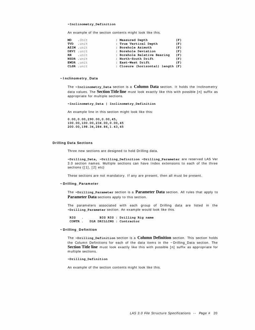
~Inclinometry_Definition
An example of the section contents might look like this.
MD .Unit : Measured Depth {F}TVD .unit : True Vertical Depth {F}AZIM .unit : Borehole Azimuth {F}DEVI .unit : Borehole Deviation {F}RB .unit : Borehole Relative Bearing {F}NSDR .unit : North-South Drift {F}EWDR .unit : East-West Drift {F}CLSR .unit : Closure (horizontal) length {F}
~Inclinometry_Data
The ~Inclinometry_Data section is a Column Data section. It holds the Inclinometry
data values. The Section Title line must look exactly like this with possible [n] suffix asappropriate for multiple sections.
~Inclinometry_Data | Inclinometry_Definition
An example line in this section might look like this:
0.00,0.00,290.00,0.00,45,100.00,100.00,234.00,0.00,45200.00,198.34,284.86,1.43,45
Drilling Data Sections
Three new sections are designed to hold Drilling data.
~Drilling_Data, ~Drilling_Definition ~Drilling_Parameter are reserved LAS Ver3.0 section names. Multiple sections can have Index extensions to each of the threesections ([1], [2] etc)
These sections are not mandatory. If any are present, then all must be present.
~Drilling_Parameter
The ~Drilling_Parameter section is a Parameter Data section. All rules that apply to
Parameter Data sections apply to this section.
The parameters associated with each group of Drilling data are listed in the~Drilling_Parameter section. An example would look like this.
RIG . BIG RIG : Drilling Rig name CONTR . DLR DRILLING : Contractor
~Drilling_Definition
The ~Drilling_Definition section is a Column Definition section. This section holdsthe Column Definitions for each of the data items in the ~Drilling_Data section. TheSection Title line must look exactly like this with possible [n] suffix as appropriate formultiple sections.
~Drilling_Definition
An example of the section contents might look like this.

LAS 3.0 File Structure Specifications -- Page # 21
DDEP .unit : Depth {F}DIST .unit : Cumulative increment of drilling. {F}HRS .unit : Hours of drilling {F}ROP .unit : Rate of Penetration {F}WOB .unit : Weight on bit {F}RPM .unit : Rotations per minute {F}TQ .unit : Torque on bit in amps {F}PUMP .unit : Mud pump pressure {F}TSPM .unit : Total strokes per minute {F}GPM .unit : Gallons per minute {F}ECD .unit : Effective circulation density {F}TBR . : Total barrels returned {F}
~Drilling_Data
The ~Drilling_Data section is a Column Data section. It holds the Drilling data values.
The Section Title line must look exactly like this with possible [n] suffix as appropriatefor multiple sections.
~Drilling_Data | Drilling_Definition
An example line in this section might look like this:
322.02,1.02,0.0,24.0,3,59,111,1199,179, 879,8.73,39323.05,2.05,0.1,37.5,2,69,118,1182,175, 861,8.73,202
Tops Data Sections
Three new sections are designed to hold Tops data.
~Tops_Data, ~Tops_Definition ~Tops_Parameter are reserved LAS Ver 3.0 sectionnames. Multiple sections can have Index extensions to each of the three sections ([1],[2] etc)
These sections are not mandatory. If any are present, then all must be present.
~Tops_Parameter
The ~Tops_Parameter section is a Parameter Data section. All rules that apply to
Parameter Data sections apply to this section.
The parameters associated with each group of Tops data are listed in the~Tops_Parameter section. An example would look like this.
TOPSRC. Logs : Formation Tops source {S} TOPDR . Subsea : Formation Tops Depth Reference {S}
~Tops_Definition
The ~Tops_Definition section is a Column Definition section. This section holds the
Column Definitions for each of the data items in the ~Tops_Data section. The SectionTitle line must look exactly like this with possible [n] suffix as appropriate for multiplesections.
~Tops_Definition
An example of the section contents might look like this.
TOPN . : Formation Name {S}TOPT .Unit : Formation Top Depth {F}TOPB .Unit : Formation Base Depth {F}
~Tops_Data
The ~Tops_Data section is a Column Data section. It holds the Tops data values. The
Section Title line must look exactly like this with possible [n] suffix as appropriate formultiple sections.

LAS 3.0 File Structure Specifications -- Page # 22
~Tops_Data | Tops_Definition
An example line in this section might look like this:
Viking,1000,1010Colony,1010.0,1020.5Sparky,1020.5,1050
Test Data Sections
Three new sections are designed to hold Test data.
~Test_Data, ~Test_Definition ~Test_Parameter are reserved LAS Ver 3.0 sectionnames. Multiple sections can have Index extensions to each of the three sections ([1],[2] etc)
These sections are not mandatory. If any are present, then all must be present.
~Test_Parameter
The ~Test_Parameter section is a Parameter Data section. All rules that apply to
Parameter Data sections apply to this section.
The parameters associated with each group of Test data are listed in the~Test_Parameter section. An example would look like this.
TESTT. DST :Test Type {S}
~Test_Definition
The ~Test_Definition section is a Column Definition section. This section holds the
Column Definitions for each of the data items in the ~Test_Data section. The SectionTitle line must look exactly like this with possible [n] suffix as appropriate for multiplesections.
~Test_Definition
An example of the section contents might look like this.
Test data contained within the LAS 3.0 format are not intended as a replacement orsubstitute for the PAS (Pressure ASCII Standard,) but are included in order to facilitatethe transfer of common test data annotations normally associated with petrophysicalanalysis presentations.
TSTN . :TEST Number {F} TSTT .unit :TEST Top Depth {F} TSTB .unit :TEST Bottom Depth {F} DDES . :TEST Recovery Description{S} ISIP .unit :Initial Shut in pressure {F} FSIP .unit :Final Shut in pressure {F} RATE .unit :Production Rate {F} BLOWD. :BLOW DESCRIPTION {S}
~Test_Data
The ~Test_Data section is a Column Data section. It holds the Test data values. The
Section Title line must look exactly like this with possible [n] suffix as appropriate formultiple sections.
~Test_Data | Test_definition
An example line in this section might look like this:
1,1500,1505,50ft oil,13243,13350,10000,TSTM2,2210,2235,Oil to surface,21451,21500,10000,Air3,2575,2589,Packer Failure,0,0,0,TSTM

LAS 3.0 File Structure Specifications -- Page # 23
LAS 3.0 Data Formats
LAS version 2 only allowed the use of floating point number format for data stored in the~ASCII section. Data stored in the Value field of any Parameter Data line was allowedto be either a floating point number or a string of text.
BS .unit 8.25 : Bit SizeLMF. Kelly Bushing : Log Measured From
Ver 3.0 allows six formats types; Floating point, Integer, Exponential, String, Dateand Time, Deg/min/sec
The optional (for floating point and String data types) format specification is placedinside a matched set of {} braces, that are placed after the DESCRIPTION field andbefore the ASSOCIATION | (bar) delimiter (if present) on any Parameter Data line orColumn Definition line.
The format specification that appears on each line either refers to the data value on thatline for Parameter Data lines, or to all data items of the corresponding channel in theColumn Data section for Column Definition lines.
If no format field is included, then the old floating point rules apply for Column Datasection channels. For Parameter Data lines, the absence of the format specificationimplies either String or Floating point format, depending on the value that is present.Typically an absence of units implies a string value, while the presence of units impliesfloating point. Since this is not a conclusive rule, the use of the format {} field onParameter Data lines is strongly recommended, and required when formats other thanString or Floating point are used.
The only exception to this rule is the format of the required DATE parameter in the ~Wellsection. If the format specification is absent, the format of the date must be{DD/MM/YYYY}.
The format specification must contain no embedded spaces. The only exception is if aformat contains both a date and time specification such as {DD/MM/YYYY hh:mm}. Thena single space can be used between the date and time format.
Floating Point {Fx.y}
The floating point format begins with the F as the first character after the { (left brace).The optional x.y value is an decimal number > 0 that expresses the total length of thefloating point number, and the number of decimals. x is the total length, while y is thenumber of decimal places. x must be at least equal to y+2 to be a valid format. The x.yvalue is optional, although if used then both x and y must appear.
If no specific format is used, then every data value must have at least one decimalplace. It is customary that every number for this channel has the same number ofdecimals, even if padding zeros must be added.
If the number being presented has fewer digits than the format, then padding spacesare appended BEFORE the number. (- dash characters are used to show spacecharacters in the examples)
12.4567 expressed with a format of: {F10.4} ---12.4567
If the number of decimal places in the format is more than the number has, thenpadding zero’s are added to the end of the number.
12.45 expressed with a format of: {F10.4} ---12.4500
If the number of decimal places in the format is less than the number has, then thenumber is rounded to the specified number of decimals.
12.456 expressed with a format of: {F10.2} -----12.46
Integer {Ix}

LAS 3.0 File Structure Specifications -- Page # 24
The Integer format begins with the I as the first character after the { (left brace). Theoptional x value is an integer >0 that expresses the total length of the integer number.If x is specified, then ALL data items must be written using this number of characters,even if padding spaces must be added. If the x value is not specified, then Integer canbe of any length. Valid examples are {I2} or {I10}.
String {Sx}
The string format begins with the S as the first character after the { (left brace). Thisimplies that the data it refers to is to interpreted as text. The optional x value is aninteger >0 that expresses the total length of the string. If x is specified, then ALL dataitems must be written using this number of characters, even if padding spaces must beadded, or extra characters removed. If the x value is not specified, then each text stringcan be of any length. Valid examples are {S} or {S32}.
Exponential {E0.00E+00}
The exponential format begins with the E as the first character after the { (left brace).The remainder of the format is the standard exponential format. The + (plus) indicatesthe placeholder for the sign (which may be + or – for any particular number) of theexponent. The number of zero’s is not restricted in any part of the format. All numbersof the channel must be written with exactly this format. Leading padding spaces can beadded as required.
Number Format Number using format
1230000 0.00E+00 1.23E+071230000 00.000E+00 12.345E+07
Date and Time {DD/MMM/YYYY hh:mm:ss}
The Date and time format uses ISO 8601 standards. The format includes both Dates(upper case letters) and Time (lower case letters) formats. Either can be used withoutthe other, or both together.
Date
The Date format uses upper case D for days, upper case M for months, and uppercase Y for years. The number of each of these letters determines the exact format.
D – Day number expressed as single digit (1-9) or 2 digit (10-31)DD – Day number expressed as 2 digit (01-31)
M – Month expressed as single digit (1-9) or 2 digit (10-12)MM – Month expressed as two number code (01 - 12)MMM – Month expressed as three character month word (JAN FEB etc)MMMM - Month expressed as full month word (January, etc)
YYYY – Year expressed as full 4 digit year. This is the only year format acceptablefor LAS 3.0
The delimiters can be – (dash ASCII 45) or / ( forward slash ASCII 47). No spacesare allowed within the date format.
Time
The Time Format uses lower case letter, h for hours, m for minutes, and s forseconds. This is the only occurrence of case sensitivity in LAS 3.0
hh – Two digit hours, (00-24)mm – two digit minutes, (00-59)ss – two digit seconds (00-59)
The delimiters between hours minutes and sections can only be the : (colon). Nospaces are allowed within the time format.
The Time format can be hh, hh:mm or hh:mm:ss

LAS 3.0 File Structure Specifications -- Page # 25
The Date and time format (if both are used) must be separated by at least onespace
Degree Minute Seconds {° ‘ "}
The format for Latitude and Longitude type may be expressed using the degree, minuteand second symbols as shown in this example.
23.45° 34.06' 58.19"
The three special symbols ° (ASCII 176) degree, ' (ASCII 39) single quote, and "(ASCII 34) double quotes. All three must be used when using this format.
Alternately, simple decimal degrees is also accepted. This would represented by thefloating point format {F}.

LAS 3.0 File Structure Specifications -- Page # 26
Three Dimension Data Arrays in Column Data sections
Three dimensional arrays don’t naturally fit into a decidedly two dimensional ASCII file.The data in the third dimension often has another index or reference than the data inthe other dimension.
LAS 3.0 provides a way to define this third dimension.
Consider an example of an ~ASCII section containing the usual two dimensional data, inthis example with two data channels measured at each depth. They are differentiatedhere with different font.
~ASCII Chan1 Chan21000.0 1.23 222.451001.0 1.56 245.091002.0 3.45 257.81
Consider the case where CHAN1 was measured five times will the logging sensor wasstationary at each depth level. These five measurements are the data items in the thirddimension, with in this case, an index of TIME.
The first dimension is depth (the first column). The second dimension is the time indexof each data sample at that depth, and the third dimension is each of the measurementsof each channel while at that one depth at each time step.
LAS 3.0 defines a convention that allows three dimensional data to be stored as twodimensional data.
In our example where CHAN1 had five different measurements taken while stopped ateach of the depths (first column), the five measurements are just listed as additionalchannels next to the first.
The CHAN1 data value (1.23) is the first measurement that you expect for each channel,and the other four remaining channels are the remaining measurements taken in timewhile at each depth. The other data channel, CHAN2, just falls normally after the fivethree dimensional array values of CHAN1 channels.
~ASCII Chan1 Chan1 Chan1 Chan1 Chan1 Chan21000.0 1.23 1.24 1.25 1.24 1.20 222.451001.0 1.56 1.57 1.58 1.59 1.55 245.091002.0 3.45 3.24 3.25 3.24 3.20 257.81
The Column Definition section for this Column Data section is used to indicate whichchannels are members of the 3D array, and which are regular 2D components. We justadd additional information to each line of the array channels in the Column Definitionsection that determines which channels are members of a 3D array.
This additional information needs to record to pieces of information;
1. This channel is a member of a 3D array.2. The index and spacing for this channel. Each sample may be distributed with time,
or distance, or rotational angle, or may just be a non-indexed list.
Rather than introducing a new indicator, the Format field {} is used. We use a specialFormat character, A, to indicate that a channel is a member of an array. If a regularformat character (F, I, S E or Dates/Time) is also needed, then add the Formatspecification immediately after the A, like {AF10.4}. The A must always be the firstcharacter in the format specification if it is used.
The index or spacing of each array member may also be recorded within the formatspecification. Use the ; (semicolon) delimiter to list the spacing and its units, after the Aand the format specification, like this;
{AF10.4;5ms}
This says that this array element is spaced 5 milliseconds after the first array element.Additional indexes are possible. Just add another ; (semicolon), then the next index, like{AF10.4;5ms;10ft}.

LAS 3.0 File Structure Specifications -- Page # 27
Each channel’s name is the same for each member of the array, as each array memberis the same channel. To indicate the difference, each name has the [ ] index suffixappended with the sequential index number within the brackets..
CHAN[1].Unit : Description {AF10.4;0ms}CHAN[2].Unit : Description {AF10.4;5ms}CHAN[3].Unit : Description {AF10.4;10ms}CHAN[4].Unit : Description {AF10.4;15ms}CHAN[5].Unit : Description {AF10.4;20ms}
This [ ] marker is not part of the channel name. It is another way of saying this channelis a member of an array. The number in the [ ] indicates the counter of the array that itis part of.
Channels that are members of a 3D array, must occur sequentially from [1] to [n], withno other channels intermixed. Different sets of 3D array channels can occur before,mixed with or after regular two dimensional data channels, but each set must becontinuous within itself.

LAS 3.0 File Structure Specifications -- Page # 28
Section Title Arrays
It is now possible to have more than one of any ~ (tilde) section, with the exception ofthe ~Version, ~Well, ~Parameter, ~Curve and ~Ascii sections.
To have more than one section with the same section title as another section, eachsection title must be suffixed with the array index brackets, [], containing a sequentialnumber, beginning with 1.
~Log_Data[1] | Log_Definition~Log_Data[2] | Log_Definition
Note that in this case, both Column Data sections share the same Column Definitionsection. This just means that they have the same type of data in each column. There isno need to have one Column Data sections for every Column Definition section if thedata contained in each column are indeed identical in all Column Data sections.
If they had any difference in column order, name, units, formats etc, then each wouldneed their own Column Definition section. In this case, each Column Definitionsection would also need [] index suffixes.
~Log_Data[1] | Log_Definition[1]~Log_Data[2] | Log_Definition[2]
If there are matching Parameter Data sections for each Column Data section, thenthey too must get the same [x] index suffix.
~Log_Parameter[1]~Log_Parameter[2]
(Note that for Log or ASCII data section, Parameter Data sections are required)
These rules apply to any section title (with the above exceptions).
Parameter Data Line Arrays
If you have two identical mnemonics in the same Parameter Data section, then youhave two choices.
1. Add different association parameters, such as for run differentiation if this is thereason for having multiple occurrences.
BS .UNIT 8.75 : BIT SIZE | RUN[1]BS .UNIT 6.25 : BIT SIZE | RUN[2]
2. Add sequential index suffixes [n] to each. The association parameters are thenoptional, and should be used if appropriate to the application.
BS[1] .UNIT 8.75 : BIT SIZE | RUN[1]BS[2] .UNIT 6.25 : BIT SIZE | RUN[2]
See the section on Association in LAS 3.0 for further examples and details of thesetechniques.
Index numbers must begin with 1 and must be sequential. They do not have to appearsequentially in the file however.

LAS 3.0 File Structure Specifications -- Page # 29
Associations in LAS 3.0
LAS 3.0 defines several association arrangements to handle the following types ofsituations. Associations allow you to connect one piece of data to another.
Often one piece of information in a LAS file is directly related to another piece of data. Acommon example is the matrix density value (SAND, LIME or DOLO density) which wasused to convert Bulk Density data to Density Porosity. To connect the two, we simplyadd the related mnemonic to the end of the Parameter Data or Column Definition line(after a new delimiter) that relates to it.
Parameter line found in ~Parameter section
MDEN .K/M3 2650 : Matrix Density
Channel definition line in ~Curve section, that depends on MDEN
DPHI .V/V Log Code : Density Porosity | MDEN
In any case, you must never specify a circular set of associations. That is, theassociation mnemonic used on one Parameter Data line, must not have as itsassociation parameter, the mnemonic found on that line. Below MDEN points to DPHI andDPHI points to MDEN!
Wrong!
MDEN .K/M3 2650 : Matrix Density | DPHI
DPHI .V/V Log Code : Density Porosity | MDEN
The following examples are only guidelines of what can be accomplished withAssociations. It is expected many other uses will be found.
Note that several of the parameter mnemonics used in the examples are now reservedLAS 3.0 mnemonics which are intended to be used as shown in these examples. SeeAppendix II.
Example 1. Storing Multiple Runs
To indicate multiple sets of any Parameter Data section parameters that may havecome from more than one logging run, LAS 3.0 defines the following technique.
~ParameterRUNS . 2 : # of Runs described in this fileRUN[1]. 2 : Run numberRUN[2]. 3 : Run number
The value must be equal to the number of runs being described in the file.
Note: If a single run is described, it is not necessary to include or use the RUNS or RUN[]parameter or associations. The RUN parameter should indicate the run number.
The RUN[] parameters (one line per run) defines the run number for each logging run.Since there are multiple RUN parameters, you must use the [] index counters.
Now for any parameter in a Parameter Data section that is associated with each run,add the matching RUN[] parameter name after the | (bar) delimiter.
BS .UNIT 8.75 : BIT SIZE | RUN[1]BS .UNIT 6.25 : BIT SIZE | RUN[2]
This then states that the first BS value applies to the run found in the value of theRUN[1] parameter found else where in the file (2 in this case).
Now two or more complete sets of run specific parameters can be included in a single~Parameter section for example.

LAS 3.0 File Structure Specifications -- Page # 30
Example 2. Column Data Channel Matrix Identification
Often there are critical parameters that are connected with certain logging data types,such as the matrix (SAND, LIME, DOLO) that was used to compute density or Neutronporosity, or environmental correction settings applied.
This becomes even more important if there are more than one of the same type ofporosity channel.
Begin by building Parameter Data lines that describe each of the values for eachapplicable parameter. This example defines two sets of matrix parameters for Neutron,density and sonic porosity channels.
#Service Company specific ParametersMATR[1] . SAND : Neutron Porosity MatrixMDEN[1] .KG/M3 2650 : Density Porosity MatrixDTMA[1] .US/M 182 : Sonic Porosity Matrix
MATR[2] . LIME : Neutron Porosity MatrixMDEN[2] .KG/M3 2710 : Density Porosity MatrixDTMA[2] .US/M 156 : Sonic Porosity Matrix
MATR[3] . DOLO : Neutron Porosity MatrixMDEN[3] .KG/M3 2870 : Density Porosity MatrixDTMA[3] .US/M 142 : Sonic Porosity Matrix
Now, in the Column Definition Section where each channel is defined, append theappropriate parameter name as an association parameter.
~Curve…NEUT1 .V/V : Neutron Porosity | MATR[1]DENS1 .V/V : Density Porosity | MDEN[1]SPOR1 .V/V : Sonic Porosity | DTMA[1]
NEUT2 .V/V : Neutron Porosity | MATR[2]DENS2 .V/V : Density Porosity | MDEN[2]SPOR2 .V/V : Sonic Porosity | DTMA[2]…
Now it is clear which channel was run on which matrix.
Example 3. Parameter Zoning
Associations are also used for zoning parameters. Zoning allows you to indicate thatcertain parameters have a certain value over a certain zone (depth interval), or thatcertain data channels in a Column Data section have certain input parameter valuesover certain intervals.
You need to define parameter(s) that define the zone interval(s). The Value of theparameter(s) will have two values, separated by the DLM character, indicating thestarting and ending depth of this zone.
In this example, matrix parameters for Neutron, Density and sonic channels havedifferent values over two intervals.
First define parameters that list the depths of each zone for each parameter involved.
NMAT_DEPTH[1].unit D1,D2 : Neutron Matrix Depth intervalNMAT_DEPTH[2].unit D2,D3 : Neutron Matrix Depth intervalDMAT_DEPTH[1].unit D1,D2 : Density Matrix Depth intervalDMAT_DEPTH[2].unit D2,D3 : Density Matrix Depth intervalSMAT_DEPTH[1].unit D1,D2 : Sonic Matrix Depth intervalSMAT_DEPTH[2].unit D2,D3 : Sonic Matrix Depth interval
Then define parameters that list the various values of the parameters in each depthinterval or zone. Add as associations the parameters that contain the depth interval thatapplies to each parameter value.
LAS 3.0 File Structure Specifications -- Page # 31
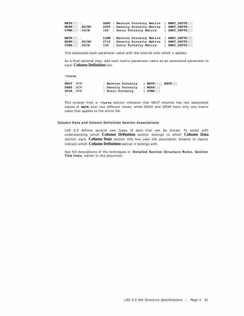
MATR[1] . SAND : Neutron Porosity Matrix | NMAT_DEPTH[1]MDEN[1] .KG/M3 2650 : Density Porosity Matrix | DMAT_DEPTH[1]DTMA[1] .US/M 182 : Sonic Porosity Matrix | SMAT_DEPTH[1]
MATR[2] . LIME : Neutron Porosity Matrix | NMAT_DEPTH[2]MDEN[2] .KG/M3 2710 : Density Porosity Matrix | DMAT_DEPTH[2]DTMA[2] .US/M 156 : Sonic Porosity Matrix | SMAT_DEPTH[2]
This associates each parameter value with the interval over which it applies.
As a final optional step, add each matrix parameter name as an associated parameter toeach Column Definition line.
~Curve…NEUT .V/V : Neutron Porosity | MATR[1], MATR[2]DENS .V/V : Density Porosity | MDEN[1]SPOR .V/V : Sonic Porosity | DTMA[1]…
This excerpt from a ~Curve section indicates that NEUT channel has two associatedvalues of MATR over two different zones, while DENS and SPOR have only one matrixvalue that applies to the entire file.
Column Data and Column Definition Section Associations
LAS 3.0 defines several new types of data that can be stored. To assist withunderstanding which Column Definition section belongs to which Column Datasection, each Column Data section title line uses the association scheme to clearly
indicate which Column Definition section it belongs with.
See full descriptions of the techniques in Detailed Section Structure Rules, SectionTitle lines, earlier in this document

LAS 3.0 File Structure Specifications -- Page # 32
Adding User Defined Data and Sections
Users can define and include their own data into Ver 3.0 LAS files.
First the user needs to decide how his data relates to the previously defined data typesfor LAS 3.0. If they fit in within a preexisting data type, they must be placed in thatsection type. Add addition sections to existing section using the [1] [2] index extensionsrather than creating your own.
If the data being added does not fall into one of predefined data types, then newsections may be defined.
New Column Data sections must be accompanied by a matching Column Definitionsection. Optionally, a matching Parameter Data section can be defined that containsindividual related data items to that which are stored in the new Column Data section.
These sections must conform to the same rules for section naming and content as allParameter Data, Column Definition and Column Data sections.
~User_Data~User_Definition~User_Parameter
Standalone _Parameter sections can also be used for unrelated one-dimensional orsingle item data. Be sure the data placed in these sections does not belong to one of theother data types stored in the file.

LAS 3.0 File Structure Specifications -- Page # 33
Appendix I: Example Ver 3.0 LAS files.
# Note! Ver 3.0 specifications are preliminary! Do not assume they will not change.# This is strictly an example to illustrate the proposed changes!
~Version VERS. 3.0 : CWLS LOG ASCII STANDARD - VERSION 3.0 WRAP. NO : ONE LINE PER DEPTH STEP DLM . COMMA : DELIMITING CHARACTER (SPACE TAB OR COMMA)
~Well#MNEM.UNIT DATA DESCRIPTION#----- ----- ---------- ------------------------- STRT .M 1660.1250 : First Index Value STOP .M 1660.8750 : Last Index Value STEP .M 0.1250 : STEP NULL . -999.25 : NULL VALUE
COMP . ANY OIL COMPANY INC. : COMPANY WELL . ANY ET AL 01-02-03-04 : WELL FLD . WILDCAT : FIELD LOC . 1-2-3-4W5M : LOCATION SRVC . ANY LOGGING COMPANY INC. : SERVICE COMPANY DATE . 13/12/1986 : Service DATE {DD/MM/YYYY}
CTRY . CA : COUNTRY
PROV . ALBERTA : PROVINCE UWI . 100010200304W500 : UNIQUE WELL ID LIC . 0123456 : LICENSE NUMBER
LATI . 45.37° 12' 58" : X LOCATION LONG . 13.22° 30' 09" : Y LOCATION GDAT . NAD83 : Geodetic Datum
~Parameter#MNEM.UNIT VALUE DESCRIPTION#-------------- ---------------- ---------------------------
#Required Parameters PDAT . GL : Permanent Data APD .M 4.2 : Above Permanent Data DREF . KB : Depth Reference (KB,DF,CB) EREF .M 234.5 : Elevation of Depth Reference RUN . 1 : Run Number
#Defined Run Related parameters RUNS . 2 : # of Runs for this well. {I} RUN[1]. 2 : Number of the indexed RUN {I} RUN[2]. 3 : Number of the indexed RUN {I}
RUN_Depth[1].M 0.0,1500.0 : Run 1 Depth Interval {F} RUN_Depth[2].M 1500.0,2513.0 : Run 2 Depth Interval {F}
#Parameters that are zoned. NMAT_Depth[1].M 523,1500 : Neutron Matrix Depth interval {F} NMAT_Depth[2].M 1500,2500 : Neutron Matrix Depth interval {F} DMAT_Depth[1].M 523,1510 : Density Matrix Depth interval {F} DMAT_Depth[2].M 1510,2510 : Density Matrix Depth interval {F}
#Parameters that have different values over different intervals MATR[1]. SAND : Neutron Porosity Matrix | NMAT_Depth[1] MATR[2]. LIME : Neutron Porosity Matrix | NMAT_Depth[2] MDEN[1].KG/M3 2650 : Neutron Porosity Matrix | DMAT_Depth[1] MDEN[2].KG/M3 2710 : Neutron Porosity Matrix | DMAT_Depth[2]
#Defined First/Last channel readings parameters FR_LR[1].M 500,100 : | DT FR_LR[2].M 523,100 : | DPHI FR_LR[3].M 520,100 : | NPHI FR_LR[4].M 500,100 : | YME FR_LR[5].M : | CDES FR_LR[6].M 510,100 : | NMR[1] FR_LR[7].M 510,100 : | NMR[2] FR_LR[8].M 510,100 : | NMR[3] FR_LR[9].M 510,100 : | NMR[4] FR_LR[10].M 510,100 : | NMR[5]
#Required parameters for AEUB compliance (but not LAS compliance
TDL .M : Total Depth Logger | RUN_Depth[1] TDD .M : Total Depth Driller | RUN_Depth[1] CSGL .M : Casing Bottom Logger | RUN_Depth[1] CSGD .M : Casing Bottom Driller | RUN_Depth[1] CSGS .MM : Casing Size | RUN_Depth[1] CSGW .KG/M : Casing Weight | RUN_Depth[1] BS .MM : Bit Size | RUN_Depth[1] MUD . : Mud type | RUN_Depth[1] MUDS . : Mud Source | RUN_Depth[1] MUDD .KG/M3 : Mud Density | RUN_Depth[1] MUDV .S : Mud Viscosity (Funnel) | RUN_Depth[1] FL .CC : Fluid Loss | RUN_Depth[1] PH . : PH | RUN_Depth[1] RM .OHMM : Resistivity of Mud | RUN_Depth[1] RMT .DEGC : Temperature of Mud | RUN_Depth[1] RMF .OHMM : Rest. of Mud Filtrate | RUN_Depth[1] RMFT .DEGC : Temp. of Mud Filtrate | RUN_Depth[1] RMC .OHMM : Rest. of Mud Cake | RUN_Depth[1]

LAS 3.0 File Structure Specifications -- Page # 34
RMCT .DEGC : Temp. of Mud Cake | RUN_Depth[1] TMAX .DEGC : Max. Recorded Temp. | RUN_Depth[1] TIMC . : Date/Time Circulation Stopped | RUN_Depth[1] TIML . : Date/Time Logger Tagged Bottom | RUN_Depth[1] UNIT . : Logging Unit Number | RUN_Depth[1] BASE . : Home Base of Logging Unit | RUN_Depth[1] ENG . : Recording Engineer | RUN_Depth[1] WIT . : Witnessed By | RUN_Depth[1]
#Next Run parameters
TDL .M : Total Depth Logger | RUN_Depth[2] TDD .M : Total Depth Driller | RUN_Depth[2] CSGL .M : Casing Bottom Logger | RUN_Depth[2] CSGD .M : Casing Bottom Driller | RUN_Depth[2] CSGS .MM : Casing Size | RUN_Depth[2] CSGW .KG/M : Casing Weight | RUN_Depth[2] BS .MM : Bit Size | RUN_Depth[2] MUD . : Mud type | RUN_Depth[2] MUDS . : Mud Source | RUN_Depth[2] MUDD .KG/M3 : Mud Density | RUN_Depth[2] MUDV .S : Mud Viscosity (Funnel) | RUN_Depth[2] FL .CC : Fluid Loss | RUN_Depth[2] PH . : PH | RUN_Depth[2] RM .OHMM : Resistivity of Mud | RUN_Depth[2] RMT .DEGC : Temperature of Mud | RUN_Depth[2] RMF .OHMM : Rest. of Mud Filtrate | RUN_Depth[2] RMFT .DEGC : Temp. of Mud Filtrate | RUN_Depth[2] RMC .OHMM : Rest. of Mud Cake | RUN_Depth[2] RMCT .DEGC : Temp. of Mud Cake | RUN_Depth[2] TMAX .DEGC : Max. Recorded Temp. | RUN_Depth[2] TIMC . : Date/Time Circulation Stopped | RUN_Depth[2] TIML . : Date/Time Logger Tagged Bottom | RUN_Depth[2] UNIT . : Logging Unit Number | RUN_Depth[2] BASE . : Home Base of Logging Unit | RUN_Depth[2] ENG . : Recording Engineer | RUN_Depth[2] WIT . : Witnessed By | RUN_Depth[2]
~Curve#MNEM.UNIT LOG CODES CURVE DESCRIPTION#------------------ ------------ ------------------------- DEPT .M : DEPTH {F} DT .US/M 123 456 789 : SONIC TRANSIT TIME {F} DPHI .V/V 123 456 789 : DENSITY POROSITY {F} | MDEN[1],MDEN[2] NPHI .V/V 123 456 789 : NEUTRON POROSITY {F} | MATR[1],MATR[2] YME .PA 123 456 789 : YOUNGS MODULES {E0.00E+00} CDES . 123 456 789 : CORE DESCRIPTION {S}# A 3D array channel begins here. It has 5 elements, and the amplitude is in# millivolts NMR[1] .mv 123 456 789 : NMR Echo Array {AF;0ms} NMR[2] .mv 123 456 789 : NMR Echo Array {AF;5ms} NMR[3] .mv 123 456 789 : NMR Echo Array {AF;10ms} NMR[4] .mv 123 456 789 : NMR Echo Array {AF;15ms} NMR[5] .mv 123 456 789 : NMR Echo Array {AF;20ms}
# The next 5 sets of 3 sections each are the newly defined sections.# The ~ names are # now defined and must not be used for other sections.
# Drilling data section
~Drilling_Parameter RIG . BIG RIG : Drilling Rig name CONTR . DLR DRILLING : Contractor
~Drilling_Definition DEPT .ft : Depth {F} DIST .ft : Cumulative increment of drilling. {F} HRS .hour : Hours of drilling {F} ROP .ft/hr : Rate of Penetration {F} WOB .klb : Weight on bit {F} RPM .RPM : Rotations per minute {F} TQ .AMPS : Torque on bit in amps {F} PUMP .psi : Mud pump pressure {F} TSPM .SPM : Total strokes per minute {F} GPM .gal/min : Gallons per minute {F} ECD .ppg : Effective circulation density {F} TBR . : Total barrels returned {F}
~Drilling_Data | Drilling_definition322.02,1.02,0.0,24.0,3.0,59.0,111.0,1199.0,179.0, 879,8.73,39323.05,2.05,0.1,37.5,2.0,69.0,118.0,1182.0,175.0, 861,8.73,202
~Core_Parameter[1] C_SRS . : Core Source {S} C_TY . : Core Type {S} C_DT . : Recovery Date (Date Core Cut) {DD/MM/YYYY} C_TP .M : Core Top Depth {F} C_BS .M : Core Base Depth {F} C_RC .M : Recovered Amount (Length) {F} C_FM . : Primary Formation Cored {S} C_DI .mm : Core Diameter {F} C_AC . : Analyzing Company {S} C_AD . : Analysis Date {DD/MM/YYYY}
~Core_Definition[1] CORT .M : Core top depth {F} CORB .M : Core Bottom Depth {F} PERM .md : Core permeability {F} CPOR .% : Core porosity {F} OIL .% : Core Oil saturation {F}

LAS 3.0 File Structure Specifications -- Page # 35
WTR .% : Core water saturation {F} Oilvol.% : Core oil volume {F} GAS .% : Core gas saturation {F} WTR .% : Core water volume {F} CDES . : Core description {S}
~Core_Data[1] | Core_Definition[1]13178.00, 13179.00, 5.00, 17.70, 41.20, 40.10, 7.30, 3.30, 67.00,13180.00, 13181.00, -999.00, -999.00, -999.00, -999.00, -999.00, -999.00, -999.00,13182.00, 13183.00, -999.00, -999.00, -999.00, -999.00, -999.00, -999.00, -999.00,13184.00, 13185.00, -999.00, -999.00, -999.00, -999.00, -999.00, -999.00, -999.00,13186.00, 13187.00, 0.10, 13.30, 23.00, 87.20, 3.00, 1.40, 71.00,13188.00, 13189.00, -999.00, -999.00, -999.00, -999.00, -999.00, -999.00, -999.00,13190.00, 13191.00, -999.00, -999.00, -999.00, -999.00, -999.00, -999.00, -999.00,13192.00, 13193.00, -999.00, -999.00, -999.00, -999.00, -999.00, -999.00, -999.00,13194.00, 13195.00, -999.00, -999.00, -999.00, -999.00, -999.00, -999.00, -999.00,13196.00, 13197.00, -999.00, -999.00, -999.00, -999.00, -999.00, -999.00, -999.00,13458.00, 13459.00, 460.00, 29.60, 28.40, 47.90, 8.40, 7.00, 40.00,13460.00, 13461.00, 430.00, 28.70, 62.00, 20.20, 17.80, 5.10, 39.00, VfgrU SliShy13462.00, 13463.00, 180.00, 263.00, 59.70, 183.00, 15.70, 5.80, 46.00, VfgrU SliShy-Shy13464.00, 13465.00, 150.00, 26.20, 48.90, 33.60, 12.80, 4.60, 48.00, VfgrU SliShy-Shy13466.00, 13467.00, 43.00, 15.40, 16.40, 40.00, 25.00, 6.70, 63.00, VFgrL VShy13468.00, 13469.00, -999.00, -999.00, -999.00, -999.00, -999.00, -999.00, -999.00,13470.00, 13471.00, -999.00, -999.00, -999.00, -999.00, -999.00, -999.00, -999.00,13472.00, 13473.00, -999.00, -999.00, -999.00, -999.00, -999.00, -999.00, -999.00, Sdy WellCem13474.00, 13475.00, -999.00, -999.00, -999.00, -999.00, -999.00, -999.00, -999.00, Sdy WellCem13476.00, 13477.00, -999.00, -999.00, -999.00, -999.00, -999.00, -999.00, -999.00, Sdy WellCem
~Core_Parameter[2] C_SRS . : Core Source {S} C_TY . : Core Type {S} C_DT . : Recovery Date (Date Core Cut) {DD/MM/YYYY} C_TP .M : Core Top Depth {F} C_BS .M : Core Base Depth {F} C_RC .M : Recovered Amount (Length) {F} C_FM . : Primary Formation Cored {S} C_DI .mm : Core Diameter {F} C_AC . : Analyzing Company {S} C_AD . : Analysis Date {DD/MM/YYYY}
~Core_Definition[2] CORT .M : Core top depth {F} CORB .M : Core Bottom Depth {F} PERM .md : Core permeability {F} CPOR .PU : Core porosity {F}
~Core_Data[2] | Core_definition[2]13178.00, 13178.00, 5.00, 17.7013180.00, 13180.00, -999.00, -999.0013182.00, 13182.00, -999.00, -999.0013184.00, 13184.00, -999.00, -999.00
~Inclinometry_Parameter I_DT . : SURVEY_DATE {DD/MM/YYYY} I_CO . : Recording Company {S} I_RF .M : Depth Datum Elevation (from MSL) {F} I_AT . : Azimuth North Type (e.g. Grid/ True) {S} I_DC .DEG : Magnetic Declination (if I_AT not magnetic) {F} I_KO .M : Kickoff Depth (M.D. of kickoff point) {F} I_GD . : Geodetic datum {S} I_ONS . : N/S Offset of well ref point to top hole {F} I_OEW .Unit : E/W Offset of well ref point to top hole {F} I_CP . : COMPUTE_METHOD (e.g. Radius of Curvature) {S} I_CS . : COORDINATE_SYSTEM_NAME eg UTM18N {S} TIEMD .M 0 : Tie Point Measured depth TIETVD .M 0 : Tie Point True Vertical depth TIEDEV .M 0 : Tie Point Deviation TIEAZM .M 0 : Tie Point Azimuth TIENSDR.M 0 : Tie Point North South drift TIEEWDR.M 0 : Tie Point East West drift
~Inclinometry_Definition MD .M : Measured Depth {F} TVD .M : True Vertical Depth {F} AZIM .DEG : Borehole Azimuth {F} DEVI .DEG : Borehole Deviation {F} RB .DEG : Relative Bearing {F}
~Inclinometry_Data | Inclinometry_definition0.00,0.00,290.00,0.00,45.0100.00,100.00,234.00,0.00,45.0200.00,198.34,284.86,1.43,45.0300.00,295.44,234.21,2.04,45.0400.00,390.71,224.04,3.93,45.0500.00,482.85,224.64,5.88,45.0600.00,571.90,204.39,7.41,45.0
~Test_Parameter TESTT. DST :Test Type {S}
~Test_Definition TSTN . :TEST Number {I} TSTT .M :TEST Top Depth {F} TSTB .M :TEST Bottom Depth {F} DDES . :TEST Recovery Description{S} ISIP .KPAA :Initial Shut in pressure {F} FSIP .KPAA :Final Shut in pressure {F} RATE .BOPD :Production Rate {F} BLOWD. :BLOW DESCRIPTION {S}
~Test_Data | Test_definition

LAS 3.0 File Structure Specifications -- Page # 36
1,1500,1505,50ft oil,13243,13350,10000,TSTM2,2210,2235,Oil to surface,21451,21500,10000,Air3,2575.0,2589.0,Packer Failure,0.0,0.0,0.0,TSTM
~Tops_Parameter TOPS. Prognosis : Formation Source {S} TOPDR. Subsea : Tops Depth Reference {S}
~Tops_Definition TOPT.M : Formation Top Depth {F} TOPB.M : Formation Base Depth {F} TOPN. : Formation Top Name {S}
~Tops_Data | Tops_Definition-1545.50,-1603.00,Viking-1603.00,-1614.80,Colony-1614.80,-1656.00,Basal Quartz
~Perforation_Parameter PERFTYPE. 55 gr BIG HOLE : Charge Type {S}
~Perforation_Definition PERFT.M : Perforation Top Depth {F} PERFB.M : Perforation Bottom Depth {F} PERFD.SHOTS/M : Shot density per meter {F}
~Perforation_Data | Perforation_Definition 545.50,550.60,12.0 551.20,554.90,12.0 575.00,595.00,12.0
~Ascii 1660.125,123.450,0.110,0.370,1.45E+12,DOLOMITE W/VUGS,10.0,12.0,14.0,18.0,13.0 1660.250,123.450,0.120,0.360,1.47E+12,LIMESTONE,12.0,15.0,21.0,35.0,25.0 1660.375,123.450,0.130,0.350,2.85E+12,LOST INTERVAL,18.0,25.0,10.0,8.0,17.0 1660.500,123.450,0.140,0.340,2.85E+12,LOST INTERVAL,18.0,25.0,10.0,8.0,17.0 1660.625,123.450,0.150,0.330,2.85E+12,LOST INTERVAL,18.0,25.0,10.0,8.0,17.0 1660.750,123.450,0.160,0.320,2.85E+12,"SANDSTONE, SHALE STREAKS",18.0,25.0,10.0,8.0,17.0 1660.875,123.450,0.170,0.310,2.85E+12,LOST INTERVAL,18.0,25.0,10.0,8.0,17.0

LAS 3.0 File Structure Specifications -- Page # 37
Appendix II: LAS Ver 3.0 Reserved Characters and Words
Several ASCII characters and words are reserved for use by the LAS Ver 3.0 standard.
The individual characters are used to separate or “delimit” individual data fields or items in LASfiles.
The restricted words are the section titles and mnemonics that are defined as part of the LAS Ver3.0 standard content rules.
Delimiters
Delimiter characters must be carefully used. Whenever possible, do not use them in thedata items stored in the LAS file. Obvious exceptions are the period which appears inmost numbers. Periods, Colon, Semicolon | (bar), [ ] and {} are only used as delimitersin Parameter Data and Column Definition lines, so they can be freely used in dataitems in Column Data sections.
Char ASCIICode
Name Delimits what Delimiter when: Used asDelimiters in:
~ 126 Tilde Start of Section title Section Title Lines
# 35 Pound Start of Comment lineFirst non-space
Parameter Datasection, ColumnDefinition section
. 46 Period MNEM and Unit First period on line
: 58 Colon Value and Description Last colon on line
; 59 Semi-Colon Format and Array Spacingindicators
Within { } formatfield
{ 123 Left Brace Begins Format
} 125 Right Brace Ends Format
After Description,before | or EOL
[ 91 Left Bracket Begins Section Title orMNEM index
] 93 Right Bracket Ends Section Title orMNEM index
Appended to anyMNEM or section
title
Parameter Datalines, Column
Definition lines
| 124 Bar Description or Format andAssociation
After Description orFormat { }
Section Title lines,Parameter Data
lines, ColumnDefinition lines
Tab 9 Tab Column Data lines
, 44 Comma
Column Data items
Parameter Datalines, Column Data
linesSpace 32 Space Unit and Value on
Parameter Data lines, andColumn Data Items
Present betweenitems
Section Title lines,Parameter Data
lines, ColumnDefinition lines
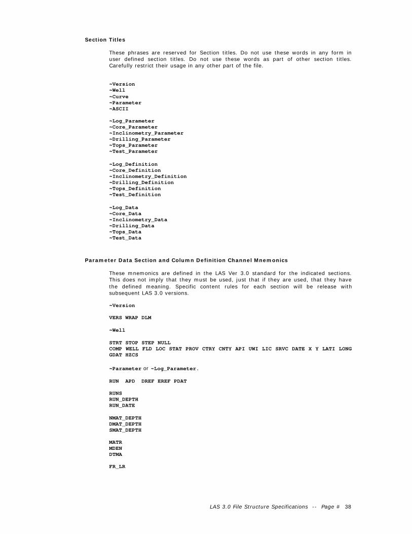
LAS 3.0 File Structure Specifications -- Page # 38
Section Titles
These phrases are reserved for Section titles. Do not use these words in any form inuser defined section titles. Do not use these words as part of other section titles.Carefully restrict their usage in any other part of the file.
~Version~Well~Curve~Parameter~ASCII
~Log_Parameter~Core_Parameter~Inclinometry_Parameter~Drilling_Parameter~Tops_Parameter~Test_Parameter
~Log_Definition~Core_Definition~Inclinometry_Definition~Drilling_Definition~Tops_Definition~Test_Definition
~Log_Data~Core_Data~Inclinometry_Data~Drilling_Data~Tops_Data~Test_Data
Parameter Data Section and Column Definition Channel Mnemonics
These mnemonics are defined in the LAS Ver 3.0 standard for the indicated sections.This does not imply that they must be used, just that if they are used, that they havethe defined meaning. Specific content rules for each section will be release withsubsequent LAS 3.0 versions.
~Version
VERS WRAP DLM
~Well
STRT STOP STEP NULLCOMP WELL FLD LOC STAT PROV CTRY CNTY API UWI LIC SRVC DATE X Y LATI LONGGDAT HZCS
~Parameter or ~Log_Parameter.
RUN APD DREF EREF PDAT
RUNSRUN_DEPTHRUN_DATE
NMAT_DEPTHDMAT_DEPTHSMAT_DEPTH
MATRMDENDTMA
FR_LR

LAS 3.0 File Structure Specifications -- Page # 39
~Core_Parameter
C_SRS C_TY C_DATE C_TOP C_BS C_RC C_FM C_DI C_AC C_AD
~Core_Definition
CORT CORB CDES
~Drilling_Definition
DDEP DIST HRS ROP WOB RPM TQ PUMP TSPM GPM ECD TBR RIG CONTR
~Inclinometry_Parameter
I_DT I_CO I_RF I_AT I_DC I_KD I_GD I_ONS I_OEW I_CP I_CS
~Inclinometry_Definition
MD TVD AZIM DEVI RB NSDR EWDR CLSR TIEMD TIETVD TIEDEVI
~Tops_Definition
TOPT TOPB TOPN TOPSRC TOPDR
~Test_Definition
TSTT TSTB TSTN DDES ISIP FSIP RATE BLOWD TESTT
Note: Also includes all array forms of these mnemonics in any Parameter Data sectionor Column Definition section as well, such as RUN[1], RUN[2] etc.

LAS 3.0 File Structure Specifications -- Page # 40
Appendix III: Definitions
Section Title Line
A line beginning with ~ that contains a Section title. Common examples are ~Version,~Well, ~Curve, ~Parameter, ~ASCII, etc.
Comment Line
A line whose first non-space character is a # (pound) character. # characters elsewhereon a line do not indicate the start of a comment at that character position.
Example:
#This is a comment line
Format Field {}
The format field is the characters found between a matched set of {} braces. Itdescribes the format used to write the data value(s) referred to by the Parameter Dataline or Column Definition line on which it is found.
Index Indicators [ ]
Found appended to mnemonics in Parameter Data lines or Column Definition lines, toindicate that there are multiple instances of that mnemonic. Also used on section titlesfor the same reason.
Parameter Data Section
A section such as the ~Parameter or ~Core_Parameter section that contains onlyParameter Data lines and comment lines.
Parameter Data Line
A line containing these elements within any section other than a Column Data section:
MNEM.UNIT VALUE : DESCRIPTION {Format} | Assoc1 Assoc2
Example:
BS.IN 8.25 : Bit Size {F13.5} | Run[1]
Column Definition Section
A section such as the ~Curve section that contains Parameter Data lines that describe
each channel of a matching Column Data section
Column Definition Line
A line within a Column Data section containing a name, unit, Log Code and Descriptionof one channel appearing in the matching Column Data section. These lines share the
same structure rules as the Parameter Data Lines.
MNEM.UNIT VALUE : DESCRIPTION {Format} | Assoc1 Assoc2
Example:
CALI.IN : Caliper Channel
Column Data Section
A section such as the ~ASCII section that contains delimited multi-Column Data. The
description of each channel is in the Column Definition section associated with theColumn Data section.

LAS 3.0 File Structure Specifications -- Page # 41
Column Data Line
A single line found in a Column Data section such as ~ASCII that contains delimitedcolumn style data channels.
Column Data Channel
Any single vertical column of data residing in a Column Data section.
Array Spacing Indicators
{AF;50ms;5ft}
For a Column Data channel that is a member of an Array, the Array SpacingIndicators are additional index information for that array member. They appear assemi-colon delimited items after the A or other Format characters within the Format field

LAS 3.0 File Structure Specifications -- Page # 42
Appendix IV: Termination Issues
Unix Line termination verses PC Line termination and its affect on the LASStandard.
Windows/DOS and MAC PC’s ASCII files use line termination characters that are actuallytwo consecutive characters: ASCII 13 then ASCII 10, referred to as CRLF or CarriageReturn & Line Feed.
Unix systems build ASCII files with only the ASCII 10 character, referred to as LF orLine Feed.
Each type of file is properly usable on the system on which they are produced. Whenfiles are transferred between the platforms, considerable confusion is possible.
The file is judged as being LAS Ver 3.0 compliant under these rules.
1. If the file is CRLF (PC) terminated and resides on a PC platform computer,it is considered a valid LAS file (assuming it passes all other LASCompliance tests).
2. If the file is LF only (UNIX) terminated and resides on a UNIX platformcomputer, it is considered a valid LAS file (assuming it passes all other LASCompliance tests).
3. If termination does not match the platform, then the file is in violation ofthe LAS Ver 3.0 Standard.
Whether the file is actually usable on any particular computer is a matter of whether theprogram reading the LAS file can handle CRLF and/or LF termination properly. Thisvaries widely. Converters are available as shareware.
The LAS Certify for Ver 3.0 LAS converts Unix terminated files to PC terminated fileswhen run.
LAS 3.0 File Structure Specifications -- Page # 43
Appendix V: Real Time Data Acquisition Considerations
Service companies have recently begun offering real time data acquisition systems.
These systems allow remote monitoring of data acquisition in the field and the remotetransfer of digital data and graphic files.
One of the expected popular digital data formats for real time transfer is LAS.
The only problem this raises is a reality of the current real time file transfer protocols.These systems can only append data to remote files, it cannot change any portion of thefiles already transferred.
The implication for LAS is that the STOP parameter value in the ~Well section, oncewritten, cannot be changed to the correct value as the file grows with new appendeddata. A file with a STOP value that does not match the final index value in the ~ASCIIsection would be a Ver 2.0 standard violation.
This is addressed in LAS Ver 3.0 by allowing the STOP value to be set to the NULL value.This is the only other legal value other than the correct value.
The ~ASCII section final value needs to be read and the STOP value needs to beupdated to this value as soon as possible.
The LAS Certify 3.0 program that is to be part of this standard, automatically performsthis correction if it is encountered.
The ~ASCII section must be the last section of the file for real time acquisition cases.The addition of new data in real time can only occur as an appending operation to theend of the file.

LAS 3.0 File Structure Specifications -- Page # 44
Appendix VI : LAS Certify Ver 3.0
LAS Certify Ver 3.0.1 is a software program designed to check the compliance of anyLAS ver 3.0 file to this documented standard. It is part of the LAS 3.0 standard.
The initial version (3.0.1) checks LAS structure rules only at this time. Content(presence of required Parameter data lines) in the ~Version and ~Well section ischecked for those specific rules as outlined above.
These checks are performed. Each general group has one or more individual checksrelated to that group. Refer to the on-line help for further details.
1. File Naming, Availability, Termination and Size.
2. ~Version VERS, WRAP, DLM present and values correct
3. Line structure syntax check delimiters, format etc.
4. Section title syntax check.
5. ~Well section mnemonics check.
6. Units on SSS and First Index channels match.
7. STRT/STOP/STEP Values match ~Ascii or ~Log_Data section.
8. _Data sections same # of channels as matching _Definition section.
9. Data sections have consistent # of channels
10. All referenced association mnemonics present.
11. Array channel _Definition section syntax check.