
Lofting - ANZ Ship Register History/Lofting_RAN... · t ! ' I I i ' ; I l! ~ 2 LOFTING TOOLS Tools...
52
. l I ,. - '·· " . ;,..· . ' I I I II I '' I l Royal Australian Navy Apprentice Training Establishment LOFTING
Transcript of Lofting - ANZ Ship Register History/Lofting_RAN... · t ! ' I I i ' ; I l! ~ 2 LOFTING TOOLS Tools...

. l
I
,. -
' ··
"
. ;,..·
. '
I
I I
II I
'' I
l
Royal Australian Navy Apprentice Training Establishment
LOFTING

MOULD LOP!'
CONTENTS PAGE NO.
lc The Mould Loft 1
l\ 2. Loft Tools 2 ~
;. De!ini tions (Hull S!'la.pe) 4 : f~it
4. . 'l'oDDS.t;."'8 Defini tiona 7 ., 5. Line Work 8
\ 6. To Draw A ~ut Grid 11
7. Defini tiona (Lines Plan) 12
8. Laying Off The Sheer Draught On Loft Floor 13
9. Fairing Ships Lines 14
J.O. Contracted Fairing 19
11. Moulds 20
12. Deck Camber - 1-lethod 1 21 folethod 2 22 Method 3 23
13. Scrieve Board 24
14. TaJd.ng Off The Plank 25
15. Lifting Off Bevels 26
16. Method Of Lifting A Bevel For A Frame Or Floor 28
"17. 'l'o Lay Off Cant Frame And Obtain Ita JfWels 30
18. To Take Off Plank Forward And Obtain te Beading Line 31
19. Half Block Model 33
\ 20. Setting Off Draught Marks On The Stem land Stern 35 "
21. lOTh. Scale Lofting 37
" 22. Shell Erpansion -~ Method 40 - ~ T.ri ation Method 42
Centre Square Me'fhod 44
' 23. Expansion Of Margin Plate 47
24. Expansion Of CUrved Raked Transom 49

' .
1
TifE MOULD LOFT
The traditional Mould Loft used in shipyards enables the shape of various parts of the vessel to be drawn full size.
It must be appreciated that the provision of adequate natural and ~rtificial lighting is essential· for work of this type.
The most important part of the loft is the working floor area on which the lines of the ship and the shape of the various structural items are drawn out full size.
The floor, constructed of wood planks, should be laid diagonally. Straight lines drawn in longitudinally and transversely on the floor might othe.rwise fall at the same places as the joints between planks and so become obscured; planks laid diagonally enable the majority of lines drawn to cross the joints at a reasonable angle.
TONG-uE f>..N D G R.OOVI:: F L.OOP.Jl'ol G'
The diagonal planking may be laid directly on the joists or on top of an ordinary planked wood floor. Planks 50 mm x 150 rnm are used, tongued and grooved to ensure that one plank cannot move in relation to the next, holding a true surface. The foundation for the floor must be substantial and level. In order that the white chalk lines are clearly visible the surface should be painted with flat black paint.
Along each side of the working floor area runs a 150 mrn wide by 50 mm deep board known as the Base Board; this is fastened permanently and checked periodically to ensure straightness. It is from this Base Board that all vertical dimensions are taken eg,waterline heights, vertical offset dimension~. The centreline, buttock line in the body plan and station lines in half breadth and profile are drawn perpendicular to the base line.
LOFT fLOOR
Du~ .. C30NF>.L PLANKING-

t ! ' I
I i ' ; I
l! ~
2
LOFTING TOOLS
Tools used on mould loft floor are:
1. Lofting pins, to pin batten to required shape. 2. Chalk line, used to mark straight lines on the floor. 3. Steel tape. The ~ero mark is some way from the end,
so that it can be placed exactly. 4. One metre folding rule. 5. French chalk, sharpened to chisel point, for drawing
in curves around battens. 6. Heavy steel rule. 7. Loft hammer with large claw. 8. Trammel -a stiff batten some 3 metres . in length on
which points are clamped at the required distance apart. It has the same use as a pair of compasses.
9. Scrieve knife , for scrieving, cutting in, lines some
10.
11.
12.
13.
1.5 mm of an inch deep on ·floor to provide a permanent record of the vessels flaired lines that will not become obscured through use and dirt. Pinning battens, of various shapes and sizes, for laying down and fairing curved lines. Tangent square "T" square, used to draw a line "normal" or square to the tangent of a curve. Clincher, a s teel plate which slips under the template wood to nails or tacks entering the floor when template is nailed together . Taking Off Battens, straight lengths of timber used for transferring offsets.
LoFT Pm£>.
FRENC.H CHALK

.... ....,. ....
I
I l-l
I
i !
I l . I I l
3
STEEL Cot~~ P ~s~E5
Sc.RJVER .
CLINC..HER TP.K INCT 0F'F B~'TTENS

:;
' I'
6
FLARE: is the opposite to tumble home, that . is the fall out of the ship's side, seen in most vessels at the fore end.
CAMBER OF BEAM: .The transverse curvature of the deck from the centreline down to the sides. This camber is used on exposed decks to drive water to the sides of the ship. Other.decks ·are often cambered. Standard camber allowed in ·freeboard calculations is one fiftieth of the beam.
SHEER: The curvature of the deck in a fore and aft direction, rising from midships to a maximum at the ends. The sheer forward is usually twice , aft. Sheer on exposed decks makes a ship seaworthy by raising the deck at the fore and after ends further from the water and by reducing the volume of water coming on the deck.
FORE FOOT: is the part connecting the keel with the stern.
CHANGE OF FRAMES: The bosom of the fore body frames look toward midships and the after body frames do the same.
Mout.oeo 0~~=>.\..lul-rr
cAMBER OF' BEAW'I
/ / ,
T
MouLDED BEP>.W'I
Mout..DED DEPTH
---Tu~N o~ 81t..GE

7
TONNAGE DEFINITIONS
The amount of water displaced or put aside by a vessel is termed her displacement. The total weight of a vessel is equal to the total w~ight of the water displaced when the vessel is floating in still waters and is at rest. The tons displacement is equal to·the under water volume of the vessel divided by 35 for salt water or 36 for fresh water.
Gross Tonnage
Is the total capacity of the ship in cubic feet divided by one hundred. It should be noted that gross tonnage is a unit of volume and hence an expression of capacity. There are three main divisions, (1) the upper deck, (2) between decks, (3) deck houses and spaces on the upper deck.
Net Tonnage
Is obtained from gross tonnage by deducting certain spaces from the gross tonnage. The principal deductions are crew spaces, navigating space and allowance for propelling power. Broadly speaking, net tonnage is gross tonnage less the non earnings capacity of the ship.
Load draught
Is the maximum draught to which the vessel ~s allowed to sink and is dependant on the freeboard.
Light Draught
Is the draught at which the vessel floats with steam up ready for sea but without stores, cargo, fuel, water, crew and their effects, passengers, luggage and provisions.
Dead Weight Tonnage (D.W.T.)
Is the difference between light draught and load draught weight with fuel~ passengers, stores, etc.
Net Dead Weight Tonnage
Is the weight of cargo only.
Cubic Capacity
This 1s g~ven 1n gra~n or bale measurement.
Grain Capacity
This is the maximum space available for cargo measured in cubic feet. The measurement being taken to the outside of the frames, (mould line of ship) and to the top of the deck beams. The grain is assumed to flow between the frames and to the top of the deck beams and occupies the maximum space available.
Bale Capacity Is the space available for cargo measured in cubic feet. The
measurement being taken from the inside of the cargo batterns on the frames and to the underside of the deck beams. This applies to a cargo of mixed commodities or when stowed comes into contact with cargo batterns and as a rule does not extend to the shell plating.

8
LINE WORK
The importance of laying out the datum lines correctly caJmot be overstressed, and meticulous care must be taken to ensure that measurements are exact and that square lines are truly square. If these lines are not set out exactly the ship may not be finished to the correct fair shape, and the structure may not align correctly.
STRAIGHT LINES: The usual method is to use a chalk line and this is essential if the line is a long one. To strike in a long straight line, the line (well chalked) is stretched tightly between the extreme points desired and raised above the floor at its center. The cord is suddenly released and allowed to snap down to the floor; the sudden impact jars loose the chalk particles adhering to the cord and a straight line is imprinted where it strikes. It is important that the cord be raised square off the floor, otherwise a slightly curved line is the result of its striking the floor at an angle.
_C._H_P\_'-_l_~_L_INe: ~ -===--~-----------------------------------------------------------------------~~~==~--~7
To draw a line square to another line. be as follows:
The method to be adopted should
Suppose it is required to draw a straight line perpendicular to XV through the point z. Mark off on each side of z equal distances Z.A and ZB. With A and B as centres respectively
.and at any convenient radius make small arcs at C. Then the line joining CZ will be perpendicular to XV.
6 X v

----- ----------· . ..
9
Distances are transferred from one part of the floor to another by using take off battens. They are either of flat triangular or of a square section.
To draw a normal to a curved line a Tangent square is employed. The head is rounded terminating at two points which are equidistant from the drawing edge of the square. Therefore, by placing the square on a curved line the ed~e bisects and is normal to the chord joining the points where the head touches the curved line. The centre of curvature of the curved line will be in this nonnal.

10
CURVED LINES: Curved lines are drawn by pinning battens made of pine of rectangular section. 'Ihey are of various size and lengths. There are three classes ·of pinning battens :
1. 2. 3.
Parallel used for regular curves Tapered at one end for curves of gradually increasing curvature Tapered in the middle for curved lines which are desired to be drawn in one length, but which have a sharp curvature on the middle portion such as the sections of a ship near midships which are usually sharp at the bilges.
The battens are held in position to the required shape by means of floor pins nailed into the floor each side of the batten at convenient intervals, It is important to note when bending a batten that the lowest number of pins possible should be used in order that the batten may take up an easy natural curve. When the (natural) curve is satisfactory then extra pins may be added to stiffen the batten while marking in the line with french chalk. The pins should be placed in pairs each side of the batten. It is always desirable to use the stiffest batten that will take the curved desired as there is a better chance of fairness by this means.
Trammels and Steel Compasses are used to draw curved lines which are arcs of large and small diameter circles respectively.

11
TO DRAW A LAYOUT GRID
In ship work where the offsets are given on waterlines and buttocks, it is necessary, before the curves of the profile, half breadth and the body plan are drawn, to prepare a grid of square lines for the offset dimensions. A perpendicular is first erected above the.hase lineA-E-Cat the point B which should be the centreline of the hull. At the point of greatest depth of the hull D on the centreline, arcs D-E and D-F are swept equal to the half beam. The same radius (B-e and B-f) is used to lay out the half beam on the base line. The beam lines on the extreme right and left sides of the grid are now drawn. The heights of the various waterlines are now laid off on the beam lines and the centreline. These are now connected with straight lines. The spacing of the buttocks is now laid off on the base line and the uppermost waterlines. These points connected by straight lines will give the buttock lines.
The grid can be checked by laying a diagonal line across the intersections of the waterlines and buttocks and, provided that they are of equal spacing, the diagonal line will exactly cross every intersection. When the waterlines and buttocks are not of the same spacing, but are equally spaced in each system, the diagonal will still cross every intersection. The grid for the longitudinal layout can be drawn in a similar manner, using the midship frame for the centreline and the fore and after perpendiculars in the same way that the half beams were used. The station or frame spacing is laid out according to the figures given on the lines plan for these ordinates. · ·
sn:~~T,oNs D.~~·wX OP. '5EC.T&ONS
~'I Dl PIC,.ONAL ')/ f.-'F D /.
/ v ~~ v
/ •/ / i '
.,- L_ / WAT~A. lL
/_ ~INf!\ lL" I
/ L e / A ~/ B c. BP-s
LIN E ~ f. ~ e""'
- ... -
BRE.P\OTH
STA1"ION:!> OQ..
~~C.TION~
~~
-
B 0 OY. P\-P\N
~uTfOC.I<. LuJI:!.S

12
DEFINITIONS (LINES PLAN)
BASE LINE: A horizontal line set underneath the profile, sheer, drawing.
WATER LINES: Are horizontal planes parallel to the base line and at given intervals.
STATIONS OR SECTIONS: Are vertical planes erected from the base line at convenient intervals (usually LWL) which cut the vessel transversely. ~
10 BliTTOCK LINES: Are the vertical planes parallel to the centre line.
DIAGONALS: Are longitudinal planes set at an angle other than 90° to the centre line intersect as many sections as is possible. These lines are mainly used for checking the fairness of the design.

13 LAYING OFF TilE SHEER DRAUGHT
ON THE LOFT FLOOR
TI-IE TERM LAYING OFF is used to express the method adopted for laying off the vessel to full size on the loft floor. The drawings from which the particulars are taken for laying off the vessel on the loft floor is the Sheer Draught which is composed of three plans, the Profile or Sheer, the Half-breadth Plan and the Body Plan, showing the moulded form of the vessel, that is the form to the outside, heel, of the steel frames.
THE PROFILE: Usually called the sheer is a longitudinal elevation with the stern placed on the right hand side. It shows the sheer of the rail, knuckle and decks at side, the position of the frame stations or sections, the level of water lines, the form of the ship at the centre line and at fixed longitudinal vertical planes, parallel to the centre line, called bow or buttock lines.
THE HALF BREADTHS: Made for the Port side only represents the form of the rail, knuckle and deck in plan, the longitudinal horizontal shape of equidistant parallel planes form the top of the keel to an assumed load line, also the position of the frame stations, the buttocks and bow lines.
THE BODY PLAN: Is the shape of the vessel at transverse vertical planes at different frame stations in length, taken square to the keel and centre line upon which is also indicated the deck, rail and knuckle (if any). In the case of yachts warships and other craft with a fixed trim the frames are usually made square to the load line. These sections show the shape of the vessel for one side only. Those which come aft of the midship section being shown on the left hand side of the centre line and those forward on the right hand side.
LINES IN PP.OFILE :iALF- ' : ~.E/\DT: I BODY PLAN ------ - . ..,., __ __ ~ _., ___ ------------ ---- - --- -____ ..___ ------ -----
RAIL CURVED CURVED CURVED
KNUCKLE CURVED CURVED CURVED
DECK CURVED CURVED CURVED
WATER-LINE STRAIGHT CURVED STRAIGHT
BU'ITOCK LINE CURVED STRAIGHT STRAIGHT
DIAGONAL CURVED CURVED CURVED
FRAME STATIONS STRAIGHT STRAIGHT CURVED

14
FAIRING SHIPS LINES
The Lines Plan as supplied by the Drawing Office is drawn to a small scale so that even the thickness of an line may represent 25 mm or more full size depending on the size of the ship and the scale used in the Lines Plan. This means that although the Lines Plan may appear fair at its small scale when it is translated to full size, it will prove to be unfair. Before the ship can be laid off, it is therefore necessary to 11fair the lines11 full scale, and hence ensure that the hull surface is smooth.
As ships are usually too large to allow the setting out to be done 1n separate Plans as in the Lines Plan, it is usual to combine the Half-Breadth Plan and Shear on a common base line, so that they are superimposed.
DAWM LINES: The first step is to put in the base line for the combined Half Breadth and Sheer parallel and about 300 mrn from the base board on one side of the loft: waterlines and buttocks are then placed parallel to this line.
Frame lines are then drawn square to these by means of a trammel. The datum lines for the body may be drawn in the desired position using the same methods.
BODY PLAN: Now using the half-breadths of "offsets" given in the Loft Book, supplied by the Drawing Office with the Lines Plan, the Body Plan can be drawn.
From the Loft Book, offsets of the frame considered can be read off at each waterline and measured along the corresponding waterline in the Body on the floor; the deck edge position at this frame can also be read from the Book and put in. Heights above the base line where the frame crosses the buttocks are also put in; a wood batten is then pinned rotmd the curve and the frame shape drawn in with French chalk.
This procedure is followed with the rema1n1ng frames in the fore and after bodies. In practice, waterlines and buttocks about 600 mm apart might well be used for the larger type of vessel.
The deck at side can now be drawn in and the frame will run into the rise-of-floor at the bottom.
TifE SHEER: The operation is to put in the outline of the centreline plane of the hull on the sheer, using contours of stem and stern and deck sheer as supplied in the Loft Book.
SETTING THE WATERLINE
The shape of the waterline may now be transferred from the Body Plan to the Half Breadth. The principle of this is illustrated in the figure below which shows frame lines (full lines in the Body) near the forward end of a vessel and a waterline.

15
A batten is laid along the waterline in the Body and distances a, b, c, d etc marked on it as shown. These offsets are now transferred to the appropriate frames in the Half Breadth marked by circled points. A batten is now pinned round the curve so formed, and the waterline drawn in with French Chalk; the batten follows a fair curve without bumps and allows a curve to be drawn in through as many points as possible, and it is important that the curve of the batten is nsighted0 by the loftsman to ensure that it is a fair curve with no sudden discontinuities.
As so often happens at this stage, it can be seen that, at frame 3, the point transferred from the Body is inside the fair curve, indicating that the offsets sent from the Drawing Office may be wrong at that frame; the distance b is therefore lifted from the Half Breadth and transferred back to the body. Other \vaterlines are transferred similarly, and if the fair waterlines show a similar trend at frame 3 then the revised frame line may be drawn in as shown by the broken line.
In many cases it will be necessary to change both some waterlines and some frame lines in order to ensure that the offsets "marry up" in Body and Half Breadth. This process marks the first stage in "fairing the lines".
FAIRING THE BUTTOCKS
\Vhen the waterlines and frames are fair, the buttocks may be drawn on the Sheer by transferring the heights above the base line at which they cross the frames in the Body, in the same manner as for the waterlines. The fairing process must now be repeated taking into account frames, waterlines and buttocks; it will be appreciated that the buttocks must cross waterlines in the same longitudinal position on both Half Breadth and Sheer, in addition to their heights of crossing the frames being correct.

16
E 0)
E C\J .
f ...0 •
0
Ill "" t(
----------~--~~--~--#H~~~~~~~~--~w~m

17
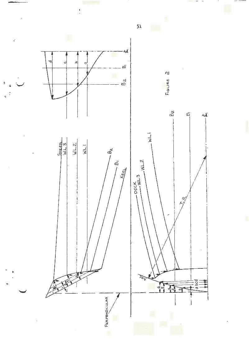
Let us assume, for instance, that the spot off on frame 3 for the ~ metre buttock, as measured from the body plan cannot be made to fair. We would also note that the intersection of this buttock ~ith the 1.2 metre waterline will not exactly make a fair curve. In this case the batten is allowed to run fair, and frame 3 in the Body Plan is altered to allow the buttock to run fair in the Profile. Now we note that there appears to be unfair spots in the waterlines in the proximity of this frame so the 1.2 metre and 1.8 metre waterlines are also altered from the new frame line in the Body Plan to make all lines come fair.
The dotted lines show the effect of the unfair spot in the height of the buttock. The full lines are fair. \'lhile the sketch only shows the forebody lines, the after lines are treated in a similar manner. Where it is only possible to lay down half the length of the ship on the floor the overlap of the lines fore and aft should encompass several frames.
111E DIAGONALS
The fairing is completed by the setting out of one or several diagonals, to ensure that the sharp bilge curvature of the frames is correct; because of the very sharp and changing curvature in this region, waterlines and buttocks alone may miss an important unfairness, but diagonals ensure complete coverage.
The endings of the diagonals in the Half Breadth are determined by the intersection of their heights on the centreline of the boat in the Body Plan. The heights are projected from the body plan to the profile, and where they meet the slope of the ends of the boat, they are projected down to the Half Breadth.
The offsets for the diagonals in the Half Breadth are measured from the body plan along the rlDl of the diagonal. These are now laid out in the Half Breadth in the same manner that waterlines would be. It is often necessary to lay each diagonal off on a separate datum to keep the diagonals from overlapping. TI1e diagonals must be fair in the Half Breadth and Sheer, passing through all points; if as sometimes happens, the diagonal is not fair, then small adjustments must be made to the lines until fairness is obtained.

H
\
cC
UJ :I lfl
\
\
~I ol 2)
1('1
w .J -\J.
<to:: a..
18
1/1 1
J ~ Ul c:( a: z
0 ~ u a:
Q ' J a: :I
'----'

19
CONTRACTED FAIRING
In order to ensure that a batten is fair when pinned round points marked on the floor, it must have a reasonable amount of curvature; this is difficult to achieve in the amidships region of the ship, as most of the waterlines and buttocks are practically straight lines.
These lines can be given greater curvature by reducing the spacing of the frames in the Half Breadth and Profile, over much of the vesse 1' s length to a half or a quarter of the actual. As the buttock crossings, heights and offsets are maintained full size, the actual fairing process is correct, but the waterlines and buttocks are given greater curvature so that a batten pinned around them is more likely to set a fair curve.
If the reduced spacing is adopted, it is usual to lay out the fore and after ends of the ship separately, due tG the large natural curvature in these parts and in order to provide information on the true shape of these regions needed in later work.
This whole process is known as "contracted fairing" and it also has the advantage that one batten can cover a greater length of each curve, so saving time in ensuring that the Joining of the lines is correct and fair. In addition larger vessels can be set out in the Loft than would otherwise be possible and due to the working area being reduced, less time and effort is wasted by the loftsman being forced to walk considerable distances in order to transfer measurements.
16 15" 14 l3 l2.. 8 7 6 4 3 2 0
IGP.EF\T~ P.. CuRV~TUR.e.
I I I I 1
l6 15 \4 13 ll. II \0 9 5 7 6 5 4 3 2. b L.-- N oRMA. I.- -~~ \-1 AL~ F Rf"'t<I E IP l,. N o R N1AL . _ ___JI 1 Fa..FIME SPP..C.I~ SPACIN C7 1 FP-f'IM~ SPA CIN &
P~o~1 L'E (~~ ONT R.P.c.T F~I R INC:r)

20
MOULDS
After the ship is faired up on the loft floor wood moulds or templates are made and supplied for.constructing many of the parts.
Owir.g to the close accuracy required in warships they are more numerous than in merchant work. It is scarcely possible to state all the moulds, for every vessel will create its own necessity; but the following are some of the principal named in order of sending out: '-"'
1. Flat Keel Plate 2. Vertical Centre Keelson 3. Stern and Stem Posts 4. Stem tubes and struts in twin screws 5. Beam camber 6. Longitudinals and Armour Shell 7. Protective Deck and Stringers 8. Backing Plating · 9. Belt ·neck ·
10. Barbette or Redoubts 11. Gun Galleries 12. Conning Tower 13. Pilot Bridge 14. Boat Davits and Chocks.
TEMPLATES OR PATTERNS TI-IAT ARE MADE FOR BOA'IWORK
Set of moulds for the stations required. Stern template, Transom template, Apron, Forward Deadwood, Stern knee, Shape of Keel.
Templates for sawn frames "if any" with the various bevel spots marked on them.
All templates must be clearly marked with all identifying lines scribed.

. ......__,
'-''
21
DECK CAMBER
Two pieces of work remain to be completed before perparation of the Scrieve Boa-rds can begin, the first being to lay off the "camber11 or "roWld of deck" which is worked at the upper deck. The amount of camber (transverse curvature of the deck) varies according to the vessel's breadth, and usually takes the form of a circular arc; it is defined as the amount by which the deck at centreline lies above the deck at the ship's side, and common amounts for merchant vessels are 6 mm per 300 mm of Moulded Breadth or 1/50 of the Breadth Moulded.
A number of methods are in common use to lay off the shape of this circular arc, and three of these are given here. The first two methods construct the camber·on one side of the centreline, so saving floor space and enabling shorter battens to be used. The third method, which draws the whole curve for both sides of the centreline, involves less work when building the Camber Mould.
METI-IOD 1
1.
2. 3. 4.
5. 6.
7. 8.
9. 10.
Let AB equal half the Moulded Breadth of the ship at the deck on the midship frame. Set up perpendicular BC equal to the required camber. Join C to A and erect AD perpendicular to CA at point A. Draw AL perpendicular to AB at point A and equal to BC Produce CL to D. Divide AB into say four equal parts with the points E,F,G. Divide CD into the same number of equal parts with the
' E' F' G' po1nts , , • Join EE', FF', GG' by straight lines. Divide AL in to the same number of equal parts, as AB and CD with the points M,N,O. Join M,N,O to C. The points on the camber curve shown ringed are given where CM cuts GG' , CN cuts FF' , CO cuts EE 1 ; the paints C and A are the end points of the curve. Repeat process for the other side.

----------------· -·· . -
B
22
In the sketch, four divisions have been used so that the picture is not confused; in practice more points would be taken, the number depending on the vessel's beam.
a b
METIIOD 2
c D E
bf I I
1' : t;<?, I /
1 l I (
---- ---- __________________ i_ -- ---------
F G-A
(a) Solid Lines
1. Let AB equal half the ~loulded Breadth of the ship at the deck on the midship frame.
2. Set up perpendicular BC equal to the reclu ired camber. 3. Describe from B a quadrant of a circle with BC
as the radius to cut All and D. 4. Divide DB into say four equal parts with the points
a, b, c and the arc CD into the same number of equal parts e, f, g.
S. Join ae, bf, cg. 6. Divide AB into four equal parts •..;ith the points E, F, G.
Erect perp~ndiculars to An at these points. 7. Using the lengths under the arc step off along perpendiculars
ae on E, bf on F and e.g on G to give point E', F' and G' in the camber curve.
8. Using point A and C as the end points draw a curve through E 1 , F 1 and G 1 •
Repeat process for the other side.
This method is r~garded as only approximate but it is very near the truth and because of its simplicity is often used on the Loft Floor.
(b) Broken Lines. Steps 1 to 5 inclusive are the same as for (a).
6. 7. 8.
Divid~ Jill into four equal 11ar.t~ with points E, F,G. Drmv lines parallel to lines ae at E, bf at F and cg at G. Using lengths under the arc step off dist<:~.nces ae on E, bf on f and cg on G. to give points on the camber curve.
This variation of method 2 is more accurate than the one given above but is by past for the simpler method in practical circumstances.

A
23
METIIOD 3 D
B
In this case the whole camber curve is dram1.
1. Point B is the vessel's centreline, draw AE equal to the Moulded Breadth of the ship at the deck on the midship frame.
2. At B erect a perpendicular BD equal to twice the camber. 3. Join D to A and E. 4. Divide DA and DE into a number of equal parts, four shown. S. The points are number 1. 2, 3 from A to D and 1, 2, 3 from
D to E. 6. Join the points of the same number together to give the lines
1-1, 2-2, 3-3; these lines are tn.ngents to the round of the beam curve ACD, \vhich is dram1 in by a batten pinned so that it touches all the lines.
E
In the sketch only a small number of tangents have been shown in order to avoid confusion; in practice DA and DE would be divided into a large number of parts and when the points are joined the camber curve will be seen to ~orm itself.'
CAMBER r.iOULD
For much of the work in the Mould Loft it is necessary to use the ca.11ber curve and a mould is therefore constructed to its shape from timber. The centreline of the camber and a horizontal datum line are scribed on the mould to enable the curve to be lined up easily.
The first use of the camber mould is for fairing the deck at centre and deck at side lines in the Sheer and the Body. As the width of the deck varies in the vessels length, the amount by which the deck at centre is above the deck at side will vary until at each end of the ship the lines will run into a common point.

24
SCRIEVE BOARD
The Scrieve board consists of a large pointed floor on which is copied the complete Body plan both sides for t.he fore and after bodies. The lines are cut in ·.~i th a uscrieve knife 11 so that they .become permanent and \vill not be obscured through use and dirt.
The Scrieve Boards are made up of a number of sheets of 12 mm plywood which, when laid out cover adequately tl1e area of th~ body plan.
Unless there is room for two complete body plan(and there rarely is) overlapping must occur. The figure below gives one r.1.ethocl of doing this which has considerable merit, the same centreline is used for both bodies and also the same Ll'lL (load waterline). The after body is placed inverted to the fore body and the places where congestion occurs (viz, at the floors on the lower frame) are well ~:eparated and these arc in places where comt)aratively few other lines cross the •·JOrk.
lNFO!Th!ATION PLACED ON THE SCRIEVE BOARD
TI1e moulded shape of every frame, floor and tank knee. The posit ion of the frames of all decks, platforms, shell plate edges, keelsons, keels, ribbons, side stringers and girders, all fore and aft bulkheads, traces of bilge ke-els, stern cants and propeller boss.
ITS PURPOSE: is that every frame, reverse frame, floor .md beam, may be tu::.T.(~d to their proper shape, punched and marked for receiving the ether parts of the structure.
P\FTEP. Boot
\.I L.W.L --- ---··-----L ',J'v', L ____ r
'-.__;·

...._,
25
TAKING OFF TI1E PLANK
With a Sheathed or Composite ship the Sheer drawing is drawn to the outside surface and it is necessary in order to obtain the moulded surface to "take off" the plank.
Forward and aft of amidships a normal to the ship's surface will generally not be either in a level or transverse plane. To "take off the plank" accurately is a problem of some difficulty. The following approximate method is found to be sufficiently accurate:
Let the waterline :md frame be as in the sketch below.
1.
2.
3.
4.
Square in from the run of the waterline BC (equal to the thickness of planking) to cut the frame at E. Take AE to the body and square in to the run of the frame to obtain the pointE'. A line through all such points as E will give approximately the moulded waterline shown as the dotted line. A line through all such points as E' will give approximately the moulded breadth of the frames shown as the dotted line. Where outside of planking intersects half siding of the stern describe a circle of radius equal to thickness of planking. Then draw a tangent inside of planking to cut circle.
I I
I
I
I I
I
I·C...m vJ. 1-..
I·Zrn W.L. I I I 1,_ /
BoDY /
-...._
----...J I -..,
I -
J
--...... .....
I ....... I .....
I .....
...... ...... .....,,
I , ......
I I" ! I
---L- I 4- ~ 2
HALF" BRt::I\DTH

26
LIFTING OFF BEVELS
The sketch below represents a wooden machine for lifting the bevel at the plate edges or at ribbands from the loft floor after the vessel has been laid down and ·faired. The distance from AB is the fore and aft distance the frames are apart from heel of frame to heel of frame, measured on the centre line of the machine. The screw 11 811 is fixed on the centre line through the groove on the moveable leg.
ScREW
LEC:r
P.EP>.DINGS
BEVE:L BoP\~o
MEUIOD:
Lift the distances as shown between consecutive scrieves (frames cut in scricve board) square off from the frame you are dealing with. Centre the distances on a piece of paper or book. See sketch below.
FR~=~.""e: BE:V~\...5 Il--l NO·
mn'"'o
I 2. 3 4 s G 7 T 2.50
6 2.1~ 300:
:;
+ 3 -·
~ t!
\:i z ~
I w 3
I I w 3 f- ~ w
en "1. !r4
\II
1\FTEP. BaoY
I
[
~
uJ i'J u 2 > <!: w
~ (i
- .J a ...n
-~ .

27
A bevel board is made of soft wood 1 metre to 1!2 metre long and of a width equal to tl1e flange of the frame.
The bevel board is placed behind the moveable arm of the wooden machine. The front edge of the moveable leg is moved to the distance between the scrieves given above and a line drawn across the board and numbered. This mark gives the distance the bar has to be opened from· the heel to the top, or the angle of opening "a''. The process is repeated until the bevels on all the frames are lifted.
BEVEL BoF>-..P-0.

28
METHOD OF LIFTING A BEVEL FOR A FRAME OR FLOOR
Take a piece of timber, cardboard or plywood about two frame spaces long and about 300 mm wide. Down the centre of this strike a base line the length of the board then erect perpendiculars to this at three points measured off to equal the spacing of three frames. edge to edge or centre line to centre line. Extend these perpendiculars across the board. Mark the middle perpendicular, with the frame munber whose bevels are required.
Tun1 to this particular frame on the Loft Body plan and make marks on its outline, which are spaced to give the desired number of bevel points on the frame.
Lay a rule on one of these marks, laying the rule as nearly at right angles as possible to the frame outline at the marked point and noting the exact measurements to the intersection of the rule \vi th the frames on each side of the chosen one,
Now take notice of the chosen station in regards to the position of it to the side of the boat, that is 1 which 1vay the bevel must slope. If the bevel formed is an acute angle, it is an under bevel, if an obtuse angle it is a standing bevel. Bevels are ahvays taken from the side of the frame that has been
. represcn ted in the body plan.
UNDER. BEVEL
OBTUSE f\NfrLE
.\ __ l ___ _ ~TP\NDINcr BE\Jr.L
Now take the board and set off the distances measured on the body plan from the chosen frame to the adjoining ones on either side of the middle perpendicular (which represents the chosen frame), one dimension will be above the base line and the other below, according to which way the bevel stru1ds.
A line is now drawn with a batten from the measurement on one perpendicular to the other t~ith the line passing through the point of intersection of the base line with the perpendicular representing the chosen frame. This line is usually straight but may be curved if necessary to pass through the three points.
To illustrate suppose that three frames or floor timbers are taken as examples A, t1 and C. 111ese are in the forebody and C is the farthest forward, B is the frame on which the bevels arc required.
The bevels board has been laid out and the peTpendiculars representing the frames drawn.
-... _,..·

29
The bevel points on B are marked in the Body plan and the measurements to the frames adjoining (A and C) have been there, for one bevel mark. It is £~'..~-! :~:.: ~ :!.!! t~e Sody plan is the after face of the frame, which will make the bevels "under•• since the forward face must be smaller due to the nm of the sides of the hull towards the bow.
Therefore, the measurement on 11 Cn on the bevel board will be taken above the base line and that on 11A11 below. Since 11B11 is the face from which the bevels
. ..__, are set off, strike in the forward side of the frame.
Now the bevel line is drawn from NA" through "B" to "C". From this board then, can be measured the amount of timber to be cut from Frame 11 B" on its forward edge to get the proper bevel at that particular spot.
The bevels for the transom may be taken in the same \'lay but the spacing of the perpendiculars of the bevel board must vary ivith each mark plotted when the transom rakes or curves. The reason for this is the variation in distance between the transom and after frame.
l ,_1-----t--TRANSOWl
FRf\tv"'E."G"
PROF.Jl-£ Boo'f
! ~ ~
FRf:\tr\E BE\IE_LS STP..TiQN B
c
00
--~-
·--·-------~------~ ___,_P....._P __ ~--------il.-.t
T RP\NSOM BE VEL
_ _ ......:::;.- ~--- ·----+---+--'' &'' Lowt=.R B~ve: L
---- --_:~_.. . .:::.::__ UPPER BE.\JEL
, .. ,, . ,..,
!

30
TO LAY OFF CANT FRAME AND OBTAIN ITS BEVELS
An ordinary Cant frame lies in a plan which is vertical but inclined to the sheer, it is adopted in order to avoid excessive beveling. The principle place in which it is now employed is for frame·s to an overhanging stern.
In the figure let AB be the plan of the Cant frame cutting the level lines at E, F, G, Hand the deck at B, square B up to B to the deck at side and level across to the body. Lift the intersections of tfle mould edge in the half breadth by placing a batten on the run of the line and marking on it the centre A and the poi~ts ~· Fz G, 2H and ~ and se~ out these points at their respective positions E , F , G , H and B then E , F2, G2, H2 and B2 is the shape of the true expanded edge.
TO OBTAIN THE BEVEL: Draw AC perpendicular to AB, AC being the width of the flange frame or some convenient length (say 150 mm). Draw CD// to AB cutting the bevel lines at k212m2n2 and d2. Then a bevel at any point such as f 2 is the square distance from the bevel edge to the moulded edge on a base equal to AC.
NB the bevel is always taken square to the frame so that it is the square distance that is required and not the distance F2 or 12
HALF= BA.EP-.DTH

. .._...,
31
TO TAKE OFF TI-lE PLAliJK FORWARD AND OBTAIN TI-lE BEADING LINE
The beading line is the intersection of the moulded or framed surface of the ship with the stern, keel and stern.post, the intersection of the outer surface with these being termed the fore edge, bottom, or aft edge of the rabbet as the case may be.
P:._r-,,-Jr··.~ t·-J ~., \ -·--·--·-·
BEPIRDING
/LIN~
···· .... .....
-~~- .• ·-·~··---· :'<":
RAB(~ET LlNS
In the sketch the shape of the ship forward is defined by the full lines BC being the fore edge of the rabbet. Up to the stem the plank is taken off in the manner as described previously resulting in the dotted moulded surface and the problem is to find the ending of this surface at the keel and stern.
The step by step method of obtainbg the beading line is set out below:
1. In the body plan, with the rabbet line as centre, scribe a circle with radius equal to normal thickness of planking.
2. Produce the inside edges of planking to meet the circle at a tangent. Where these lines cross the half siding of stern and keel, project these intersections 0, P, Q, over
3.
4.
s.
6.
7.
to the profile to the corresponding frame. Square a line from any point E on the water line normal to the stern to cut the frames 1, 2 and 3 at F, G, H. From points F, G and H in the Profile draw lines square to the original normal. Project the height of points G, F, and H in the Profile to the moulded surface at frrunes 1, 2 and 3 in the body plan. These points being called c1, F1 and H1. Take half breadths of G 1, F 1 and H1 and set in Profile from G, F and H respectivelyo Giving points h, k, j . From the point E set off the distance equal to the half siding of the stern E.C. From C draw a line (C, L) parallel to our original normal. At point C on the rabbet line draw a circle radius equal to the nominal thickness of planking.
8. Take a fair line through h, k and j and finish as a tangent to the circle and cutting CL at M.
9. From point M square up a line till i~ cuts the original normal at point N.
10. The faired line through points 0, P, Q and N is the bearling line,

32

33
HALF BLOCK MODEL
1' Where the model is made to a set of lines .2. Where the model is made' first and the lines lifted from it,
L Taking the first case:
The model is made to the lines so that the different information may be fomd:
a.
b.
In the case of steel vessels plate sight edges, butts, decks, bulkheads are marked onto the hull of the model so that shell plate etc may be ordered well before it will be used. The sight edges are marked on with the help of thin battens which are laid on in their natural positions and held in place with elastic bands and the edgr marked in with Indian Ink.
Other information fow1d, the comparison of o hull design against another (this would be in the case of large pleasure yacht through to commercifl vessels). This is done by ta~k testing a full model in a long tank in which all sorts of conditions that tl'e ship in real life is likely to encounter are assimil~;ed. (This inclu~es waves, wind, heel angles, variou1 changes of trim and stability tests, etc) - all o scale Fd crlculated electronically.
2. Tak~ng the second case:
Mooi::L
In the second case the flOdel is made first until a desirable shape is obtained, in t:P,is case the;re may be qur· te a few . models made. Designing a boat by this method s good p actice because a three dimensional picture may be seen and is o~ good value to a customer lvho cannot tmderstand a lin s plan. J.l From the model the lines are taken off either by the use of a base board, horse and pointer or by cutting the model at each section and plotting the measurements from the wa.terlines and buttocks which are drawn onto the sect~on. The o ~sets are tabulated and the design is lofted on the loft floor ~11 size and £aired in.
BLOC..K.S
~ur ON N'loDEL

I -2~LATE ~OR FRAM~~
BACKING BOARD
(
.. . ~r
Foo.e: ·Se:c:.T>ON 0'" F\ T~PtC.AL H"L" BLot.J<. Mooe:L - -
BR-IDG-E (HoRse)
.;.
DP..PIWING PE~J
(
\)>1 -1:>.

35
SETTING OFF DRAUGHT MARKS ON TilE STEM AND STERN
These are placed on both sides of the term and stern, by means of which the draught of water that the ship draws at any time when afloat may be correctly ascertained.
Figure 1 shows the outline of a vessel on the stocks. The bottom of the keel should be a straight line. It is tested by placing "dark sight" boards,
~ like H in Figure 2 with an open space P of about 5 mm on a level with the bottom of the keel at various positions in the length of the vessel A, B, C and adjusting A and C until the sight holes are in a line with B and each other, and so that the sight edge embraces the extreme bottom points of the keel.
The sight line may then be produced on to D, any upright at the stem, and a temporary shore placed in for the purpose will secure L in the same way. To these points L and D a straight edge is attached. Then stand the measuring batten G as shown, on top of this keeping it square to the edge LD with set square K, and a line off the marks on the stern to about 1 metre above the load line.
It is not necessary to place any figures, except in shallow draught boats, below about 1 metre, as the ship is never likely to draw less water. The after end may be lined off in the same n~ner.
Tile figures are stencilled in and then cut with a chisel. are 100 mm deep and are set out as shown below.
The figures

DRAUG-HT
I I
\
\ \ ., \ ~ \ ~
~----Jd:!
II~ ul
I I
H
Ft G-URE 2

.. \._/
' .
e •
37
lOTH SCALE LOFTING
OPTICAL MARKING OF PLATES
A drawing, 1/10th full size is made of each portion of the structure and this drawing is photographed on a·glass plate negative 1/10th the size of the drawing, or l/100th ·full size. The thickness of the . lines drawn is as fine as practicable and corners are drawn as sharp and square as required.
The process of marking out the plates takes place in a darkened tower at the top of which is a projector which projects the slide on to the plate lying horizontally beneath. The outline of the plate is then marked in the conventional manner by centre punchi~g.
Obviously any slight shrinkage of the paper or tracing film during the drawing of the original wi·ll result iri considerable errors in the marked off plates; standard .marks are therefore put in on the drawing at' specified distances apart. When the image is projected adjustments can be made so that the marks show their correct spacing on the plate bei~g marked off.
Optical lofting is not widely used, but besides its modest cost it can be used to mark out thin plate or sheet, which cannot be easily profiled burned automatically without severe distortion. It can 1e use~ as a very economical method of marki.ng out rectilinear plates which can biJ cut by ~hear~ or guillotine.
Special precautions are to be taken .to a o~d t1.1ouble from v!ibiati1 and building distortion from wind. .
BLP>..c.K OuT CuRTAINS
I I I I I
I I
PAo.Je c.ioR R.s:N'\Cll"E Cci'.ITI=l.OLE o fP-OlV'\ V\Ja~K~HOP !=' L...OOR.
~ t-----l I I t-----'==--==::...;;:::;:::::;:;:~,..__
!\ ~ I I
I ~0..\E.C.T~A.
\TowE.P.I
I I I I I I I \ \
I I
\ [2j \ fZ1
\ ~ \
\ 0 \ 0 \ ~·
0 LWIF>.P..Klt.J/1 O!:F T ABLE VJiiH
R. 0 L l .• E P.S.

38
SMALL SCALE LOFTING FOR AUTO~~TIC CUTTING MACHINE
In this system the shapes of the plates are drawn 1/lOth full size, exactly as they are required to be cut (with certain exceptions mentioned below) on sheets of treated aluminium, plastic or stabilized plastic film.
Care must be taken with the inking of these lines as the cutting machine is very sensitive to change of thickness. Extreme care is required in the preparation of the drawings and it is a common practice to use a pair of magnifying lenses or other form of magnification to reduce eye strain.
The exception regarding the actual drawing work is that nominally sharp corners are carefully tailored with a knife to enable the sensing cell of the cutting machine to follow a smooth curve. If the corners are drawn absolutely square, the machine over-runs, loses the line, and stops.
1\ LEP.D-IN CuT P.,,- A.N
OBTUSE P-..NC7LE. Muo:.T BE PRoviDG.D FoP. GuT OuTs--....___
P..NG·LE'::> Sr·nF\LI..ER. T1-11!>.N 70° MusT HP..vE T r\E. (oRNEP.S CuT OFF
//
CoNNE.C..T\NCr PHi( ES
MusT BE DRJ>.WN IN / FoP- P-. C..oNi1NUOU5
GuT--~
--~---
J_l/_j DETAIL OF lro ScALE DRP-WIN&
Tr1U.I.E MusT BE No Mf'\RKS NEF>.R THi:O: ln·J.t-_ ~
L. IN~ Tv\tJr,T t--loT BE: BROKE ~,.
LtNE MusT bE F\ C1N~T~NT WiDTH.
Drawings are also prepared to show the method of r~sting the pieces to be cut from the plate and the technique is to arrange these in such a manner that the machine makes the longest single cut on one plate without stopping (see sketch). This holds all the pieces together and prevents them falling away from the supports, but in some cases it is necessary to add bridges at strategic points around the cut to hold the pieces in position. These bridges are later cut by hand when the plate is removed from the machine.
SKETCH Of CUTTING I.JNE: ON .fl.ill._

39
The cutting drawings must be prepared strictly in accordance with the instructions for the type of cutting machine for which it has been prepared. In particular the thickness of the lines of the drawing must suit the design of the sensing unit. For some machines the lines may require to be as narrow as between 0. 008 and 0. 010 in width for the sensing unit, and hence the machine, to operate satisfactorily when cutting on 1/lOth scale.
The operating instructions must also be correctly followed as regards the use of the tracing unit which the operator guides along the cutting line to control the cutting head. For some machines the tracing unit must be made to follow the middle of the cutting line and for others to follow one edge of the line.
The sketches below illustrate the general arrangement of two types of machine. In the first type the cutting drawing is secured on a rotary table integral with the control console and in the second type on a flat table separate from the control panel. Some machines are designed for cutting a single plate and others for cutting two identical plates simultaneously using the same 1/lOth scale drawing.
PLATE CUTTING MACHINES
IIDnfo~~ DRAW\N<r CAI\IIli<Jl.. llUR N8
I Pl"TE
Ct.IH":D L PANEL j I I I
COWTAOL Plt.IJE<... 6UIO,~f~ Pl~f"E:
PlATE" DIIAWIN<i- CAIIIliER

40
SHELL EXPANSION
DIAGONAL METIIOD
a. CONSTRUCTION
In Figure 1 let xx and yy represent the top and bottom of the shell plates respectively in the body plan. Draw the line NN passing through the girth centre of each frame from xx to yy. Draw the diagonals, aof, boe, bog, co£, etc. "---"
3
r:ICURF. 1
b. EXPANSION OF DIAGONALS
In Figure 2 set of 2 set off 2 frame spJces as shown and erect a perpendicular at each frame. In Figure 1 girth ~e diagonal "aof" and apply
S.taHT
Eou-E XX
this to Figure 2 11ao" to one frame and "afl' to the other. A line drawn through a, o and f will give the true length of the diagonal A. The remaining diagonals expanded in siniilar manner. ·
--ExPP.NOEO of
0

Oi.e
41
c. EXPANSION OF PLATE (SIGHT) EDGES
In Figure 3 set off the frame spacing as shown and erect perpendiculars. From Figure 1 girth the sight edge xx from a to b, a to c, a to d, and apply to their respective frames in Figure 3. A batten through these spots will give the trJe expansion of the top sight edge xx. The bottom sight edge yy is expanded in c. :imil ar manner. · · ·
4 6 7
o \e ExPANDED
FIGURE 3
d. APPLICATION
Apply a batten to the top and bottom expanded sight edges xx and yy and mark on these bat.:ens the expanded frames. Pin one end of each batten a distance apart equal to the girth distance from x to y on frame 3. From "a" apply the expanded diagonal A until it meets frame 5 on yy. Similarly from "e" apply expanded diagonal F till it meets fratle 5 on xx.
9
Similarly by using the expanded diagonals B, E, C and D the positions of the expanded sight edges xx and yy are found.
The expanded girth centre NN, is used as a check to test the of the expansion
NOTE: Diagonal not necessarily straight
FIGURE 4
y

42
TRIANGULATION METI-IOD
a. CONSTRUCTION
In Figure 1 let xx and yy edge respectively in the body plan. centre of each frame at PQRSTV etc. straight lines.
represent the top sight edge and bottom sight Draw the·line 00 passing through the girth Draw the diagonals aQ,bPj, bR etc, these being
6
ioP St~Hi E oG-e::
Y Bc:rrr~Wl SIG-HT EoG-E..
FIGURE 1
b. EXPANSION OF DIAGONALS
In Figure 2 AB represents the normal frame spacing, AC is drawn perpendicular to AB. On AC mark the diagonal aQ. joint Q to B, then this line QB is the expanded diagonal.
-....--.--E: :;.<.PAN0£0 DIP.G-01-JAL
a ;:--------..-:~---fl.. B
FIGURE 2
c, EXPANSION OF SIG~IT EDGE
This is done in the same manner as shown previously in Figure 3. (Shell Expansion by Diagonal method). Pick up the expanded frrune spaces.

\._..!
,·
43
4 5 6 2. 3
y..
NOP.IYlAL 0 F~AN\6 SPACING-
y
FIGURE 3
d. APPLICATION
TI1ese expanded frame spaces are marked A on the battens xx, oo and yy . Pin one end of each batten at a distance apart of the girth distance aP and Ph which will be the girth between the sight edges on frame 1. Apply from a on xx the expanded diagonal which is obtained from Figure 2 and in this case is represented by aQB (Figure 4) •
FIGURE 4
NOTE: Expansion by triangulation is more accurate than the previous method and is the method most commonly used. In general practice allowance must be made for laps and butts in the actual expansion.

44
CENTRE SQUARE ME TIIOD
a. CONSTRUCTION
In Figure 1 let xx and yy represent.the top and bottom sight edges respectively in the body plan. Draw the chords ah; bJ, cK and ell etc connecting the top and bottom sight edges.
\
6
' }'
FIGURE 1
b. EXPANSION OP SIGHT EDGES
This is done in same manner as in the previous method and the expanded frames obtained.
c. SQUARING TilE CENTRE . SPOTS IN 'IHE BODY PLAN
From the chord at frame 7 in Figure 1 select a spot that is about midway between the sight edges and mark the spot A. Take a square and hold it along the chord at frame 7 at the spot A, where the blade crosses the chord at frame 6, mark this spot B. Now reverse the square and hold it on the chord of frame 6 with the blade on the spot A (chord 7). At the spot where the square rests on chord 6, mark the spot C, if these straight lines of chords at each frame were parallel there would be no twist in the· plate and spots B and C would be identical, but if there is a twist in the plate there will be a slight space between B and C, divide this space evenly and mark the spot A on chord 6 which becomes a new square root.
By using the edge of the square as a straight edge, set the square at spot s A on chords 6 and 7 at the same time crossing t he curve frame line 7 on which mark the spot D.

.·
45
This spot D will be the working spot from which the actual development is done. Next hold the square on chord 6 at spot A and square to spot A (chord 6) and mark C on chord 5. Halve this distance between B and C on chord 5 and obtain the spot A. Repeat the performance of producing the spots A on chords 5 a.'l·'. 6 back to the curved frame line 6 thus obtaining the spot D. The spot D is thus obtained on each curved frame line in a similar manner for the length of the plate.
The expansion of the sight edges having already been obtained, the width of the plate between the' sight edges must also be obtained. The plate being bent around curved frames, the frames must be girthed or measured around the curve to obtain the width between the sight edges. · Ttds is done with a batten l'o'hich has the same thickness as the plate if there is very much curvature.
With D as the working spot on frame 7, girth frame 7 and mark the top and bottom sight edges on the batten. With the same batten and holding it at the spot D on frame 6, girth f~ame 6 and mark the top and bottom sight edges on the batten. This is ·repeated for each frame remembering that D is the working spot in each case.
For convenience a developing square is made as shown in Figure 2 and the girthed spots are transferre.d from this girth batten to the edge of the s'luare.
DEVELOPING SQUARE
d. APPLICATION
FIGURE 2 I[ I
I
I
11
1
I
D
l I
A straight. line repres~nting frame 1 is d~aw~ land ~~he upper and lower sight edge expansion batt:ens placed in their appro:d;nat . · pos:iti.ons as shown in Figu"!e 3. The developing square on which the girth spots have been placed is set on top of these battens which are fastened at frame 1 to the spread between the girth spots for this frame. Then place a nail in the floor at the working spo.t D on t'rame 1.

46
Hold the square against this nail and mark along the blade of this square approximately where frame 2 will cross obtaining the spot B. Move the square ahead to frame 2 on the sight edge expansion battens at the same time holding the blade of the square against the nail at frame 1.
With the square in this position mark C on frame 2, then remove the nail from frame 1 and place it midway between the spots B and C on the frame 2 for the spot D. Hold the square against this nail in order to set the edge battens properly at frame 2, now hold the developing square against this nail at frame 2 and mark along the blade at approximately where frame 3 will cross, obtaining the spot B, then move the square ahead to frame 3 on the sight edge expansion battens at the same time holding the square against this nail at frame 2, mark the spot C . · ·
Remove the nail from frame 2 and place it midway between B and C on frame 3, for spot D. Hold the square against this nail to set the edge battens properly at frame 3. Continue this construction at each frame until the end of the development is reached.
NOTE: In all shell expansions particular attention should be given to the plate, which is to be expanded, as to whether it is an inside or an outside strake so that allowance can be made for laps.
2 3
D D ----------_3 ---------- --------
's
·.

•
47
EXPANSION OF MARGIN PLATE.
Place the level line g.o. in the Body (Fig. 2 ), lift points g, h, cl, m etc., from the centre line, and place them in the Half Breadth on their respective frames. Then girth this line for the position of the frames and place these expanded on a straight line about the midship frame, from which points, square lines indefinitely above and below. Lift the widths of the margin plate below the level line on the Body sections gD, hF, etc. and transfer them to their respective expanded frame stations below the level line.
Pass a curve through the spots which will give the lower edge of the margin plate.
The top edge may be found on a large section, or on the left floor Body, by drawing the curve of the plate and its position on the inner edge, see Fig. 1.
Then girth from g, h, i, etc., to each inner point "a11
, and set these girths off above the expansion line g, o, on their respective stations and draw a curve through the spots. This is the expanded top edge of the margin plate.
a
Pu:~on:
FtGURE. 1._

48
\\\ 0
/\ ~TER Boo'J' (DouBLE. BoTioM)
FIG-UP.E 2
8 7 6 5 4
g
~ h .
~ J: Q_ m n 0 p
NoP. IYIAI.. -- FP-AmE. .,..__ h SPI\ClNG
8 7 6 5 4- 3
f---_ rft_ j L tJ p s u
(j h.ll r . L t rn (\ 0 f'
II
r- T D F H K M 0

..
49
TI-lE PROCEDURE ADOPTED TO ARRIVE AT, (AND EXPAND A) CURVED RAKING TRANSOM
Having already established the positions of:-
The Waterlines, (Chine) Sheer in the ~Breadths Plan,
•.•.....•....... the Sections and False Transom in the Body
P la.1 ...•.•.... , . . . . the Keel, Buttocks, Sheer and Tr·ansom
Angle in the Profile,
It is necessary to find 1st the outboard edge of the transom
in the Profile and~ Breadths Plan.
To do this:-
Plumb a perpendicular down from the Profile to the ~ Breadths Plan, strike in an arc of a given radius at a tangent to this perpendicular at the centre line of the ~Breadths Plan,
Next measure the distances from the perpendicular to the arc, along each Buttock line, then draw lines parallel too, and spaced these distances from the centre line of the transom in the Profile.
(Thus giving the ends of the buttocks up the transom face) Now from the Body Plan measure the heights of the top and bottom intersections of the buttocks with the False transom (or End Elevation of it) project these heights to the Profile and finish off the buttocks.
Now in the Body Plan measure off the ~ Breadths of a number of datum points (on the out board edge of the false transom) and transfer to the ~ Breadths Plun cutting the arc, now measure the distances from the perpendicular to these points and transfer to the Profile at right angles to the centre line of the transom to intersect their respective heights (\vhich have to be transferred from the Body Plan). This then gives u nwnber of point.s to fair in the outboard edge of the transom in Profile,
Project all necessary points down to the ~ Breadths Plan to obtain the outboard edge in this view.
Now to expand the Transom
From the points where the sheer, (chine) and waterlines intersect the edge of the transom in the ~ Breadths Plan scribe an arc of the correct radius, to the centre line, and from the respective points in the Profile, square lines from the centre line of the transom out board.
Girth around the waterline arc's in the ~ Breadths Plan (obtaining their lengths and position of the buttocks) transfer these lengths to their respective positions jn tJ1e Profile, mc~a.'iured from the centre line of the transom. The height of the buttocks can be now squared across to their respective positions and the expanded }"2 Breadth of the transom drawn in.
If the Plank thickness has not already been removed, it must be done so now in the approved manner.
The bevels to a1101~· the planking to fit must be obtained also7 remembti'ing tha 1: t.h is shape (f:.xpancted '1 uw;omj 1 ~' t:he ~ifter face.

50
~ ...-! co w rr. -._..~
N· J .
a:l " w u.. .
UJ 0
w w ~ 3
_] Ul
ul >
~ (\j ~ z ro
cO co
I
0 I In
z: <(
('{1 rJ ..... a: w.....1 _J _..J I 1-w3 ~ s :r. UJ
Vl f[l
C\1 ..... cO <(
u... .-j
cc 0
l ~.
I ~
I . l I I ..J"l I. ' ! %
(( ...1
a.. Ill \JJ z
_Jl
.J ~
f a: 0 z
;;
----'-"
l\ ' li w t w
---~-
0
! v ~
"
('() UJ__j
· J3
,. I
I . I
rJ . .J :3
I
I I
I I
I
----~
ci5
nJ ·--co
tU cQ
~T z UJ Q.
0: uJ
Q_
51
C"\J
Ul r:f.
J ~
L,;.:
C\.1 o5 Ad( cO
I _l
~
,-
~11 ru -! 3
,y • / I
Q;. I f....'
l
II __

52
f .
,.
\
~~ o/ z w Q.. .
a: ~
-co ro
t:t'
i I
• :J:
b . <(
UJ cc
.c:Q 2 !:\1 • Sl~ w z uJ ...! 6: -a::~ lL
!-'-- 2 u. z Q_
01-1 0 11.1
Ul llJ :r (1. :J: ~ cr 1-:x: tl 0
l.fl0!-=
w <.!! 0 ;:, 2 w
1:1: - 0:: 1- UJ ct: cow
tt. ~ D <J1 z u 'Z - 4. 3 cO ri. ll) t-
J.. a: ·o <J1 z ;c&:
<1'1 1-UJ ~ z z :z ([
_J- w .J
_10-
-..


![AD PO0O097o7 · 2011. 5. 14. · lofting", in analogy with the drafting procedure known as lofting. Ps P t[F], which is linearly whitruled in both directions, is termed bilinear,](https://static.fdocuments.in/doc/165x107/60811d10765cf350b64b4a14/ad-po0o097o7-2011-5-14-lofting-in-analogy-with-the-drafting-procedure.jpg)


![Lofting Rev 3 Final 2009-07-30.pptx [Read-Only]adfisher/7962-09/Lofting-HO.pdf · 8/1/2009 1 July30, 2009 Brake & Wheel Assembly Team What is Lofting? A loft combines two or more](https://static.fdocuments.in/doc/165x107/5b854b5a7f8b9ae5498e16cf/lofting-rev-3-final-2009-07-30pptx-read-only-adfisher7962-09lofting-hopdf.jpg)