Loft Conversions and the Building...
36
A City and County of Swansea Dinas a Sir Abertawe Environment Department The Guildhall, Swansea SA1 4PE Tel No: (01792) 635636 Fax No: (01792) 648079 e-mail: www.swansea.gov.uk/bcon Minicom: (01792) 635609 LOFT CONVERSIONS and the BUILDING REGULATIONS Simplified Guidance LOCAL AUTHORITY BUILDING CONTROL SERVICES 2005 Rev1.
Transcript of Loft Conversions and the Building...
A City and County of Swansea
Dinas a Sir Abertawe
Environment Department The Guildhall, Swansea SA1 4PE
Tel No: (01792) 635636 Fax No: (01792) 648079 e-mail: www.swansea.gov.uk/bcon
Minicom: (01792) 635609
LOFT CONVERSIONS
and the
BUILDING REGULATIONS
Simplified Guidance
LOCAL AUTHORITY BUILDING CONTROL SERVICES
2005 Rev1.
C O N T E N T S
Page 1:00 Introduction 3 2:00 Design Considerations 4 3:00 Structural Stability 5 4:00 Fire Safety 8 5:00 Ventilation 18 6:00 Staircase Access 21 7:00 Thermal Insulation 26 8:00 Electrical Safety 27 9:00 Typical Problems and Solutions 28 10:00 Checklist 32
The original edition of this document was developed by colleagues at Exeter City Council to whom
Local Authority Building Control Wales are obliged
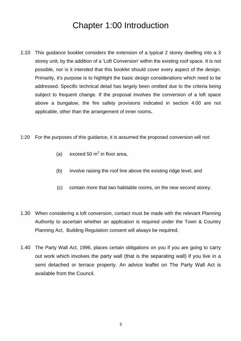
Chapter 1:00 Introduction 1:10 This guidance booklet considers the extension of a typical 2 storey dwelling into a 3
storey unit, by the addition of a 'Loft Conversion' within the existing roof space. It is not
possible, nor is it intended that this booklet should cover every aspect of the design.
Primarily, it's purpose is to highlight the basic design considerations which need to be
addressed. Specific technical detail has largely been omitted due to the criteria being
subject to frequent change. If the proposal involves the conversion of a loft space
above a bungalow, the fire safety provisions indicated in section 4:00 are not
applicable, other than the arrangement of inner rooms.
1:20 For the purposes of this guidance, it is assumed the proposed conversion will not:
(a) exceed 50 m2 in floor area,
(b) involve raising the roof line above the existing ridge level, and
(c) contain more that two habitable rooms, on the new second storey.
1.30 When considering a loft conversion, contact must be made with the relevant Planning
Authority to ascertain whether an application is required under the Town & Country
Planning Act, Building Regulation consent will always be required.
1.40 The Party Wall Act, 1996, places certain obligations on you if you are going to carry
out work which involves the party wall (that is the separating wall) if you live in a
semi detached or terrace property. An advice leaflet on The Party Wall Act is
available from the Council.
3

2:00 DESIGN CONSIDERATIONS
2:10 The booklet will examine what we consider to be the most important areas of the
design, and those, which through experience, have caused problems during both the
design and construction stages.
2:20 Structural Stability of the dwelling, considering both the existing structure and the
proposed alterations, with reference to the supporting Approved Document A, of
Schedule 1 to the Building Regulations.
2:30 Fire Safety of the proposed conversion with reference to the Approved Document B,
of Schedule 1 to the Building Regulations.
2:40 Ventilation of the rooms and the control of condensation in roofs, with reference to
the Approved Document C and F, of Schedule 1 to the Building Regulations.
2:50 Staircase provision to the new storey with reference to the Approved Document K, of
Schedule 1 to the Building Regulations.
2:60 Thermal Insulation of the conversion with reference to the Approved Document L, of
Schedule 1 to the Building Regulations.
4
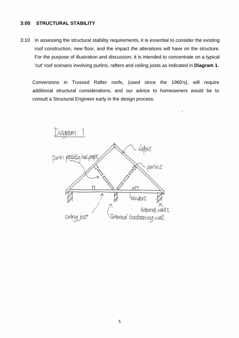
3:00 STRUCTURAL STABILITY
3:10 In assessing the structural stability requirements, it is essential to consider the existing
roof construction, new floor, and the impact the alterations will have on the structure.
For the purpose of illustration and discussion, it is intended to concentrate on a typical
'cut' roof scenario involving purlins, rafters and ceiling joists as indicated in Diagram 1.
Conversions in Trussed Rafter roofs, (used since the 1960's), will require
additional structural considerations, and our advice to homeowners would be to
consult a Structural Engineer early in the design process.
5
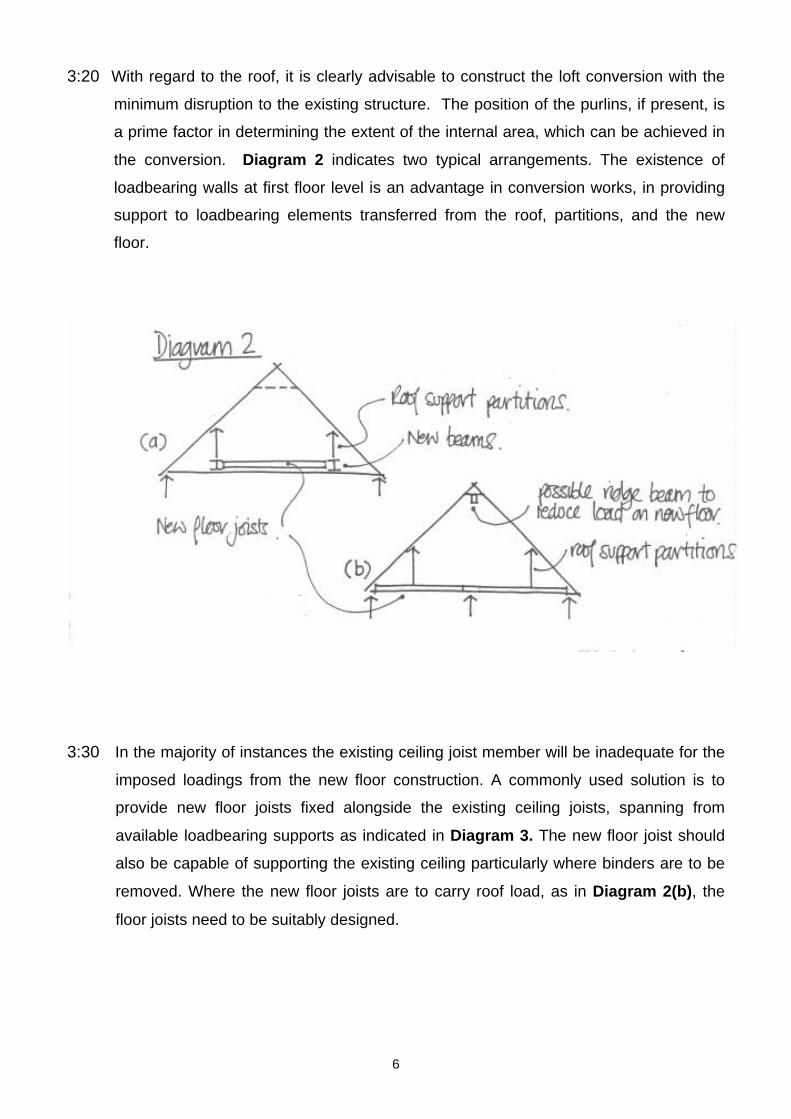
3:20 With regard to the roof, it is clearly advisable to construct the loft conversion with the
minimum disruption to the existing structure. The position of the purlins, if present, is
a prime factor in determining the extent of the internal area, which can be achieved in
the conversion. Diagram 2 indicates two typical arrangements. The existence of
loadbearing walls at first floor level is an advantage in conversion works, in providing
support to loadbearing elements transferred from the roof, partitions, and the new
floor.
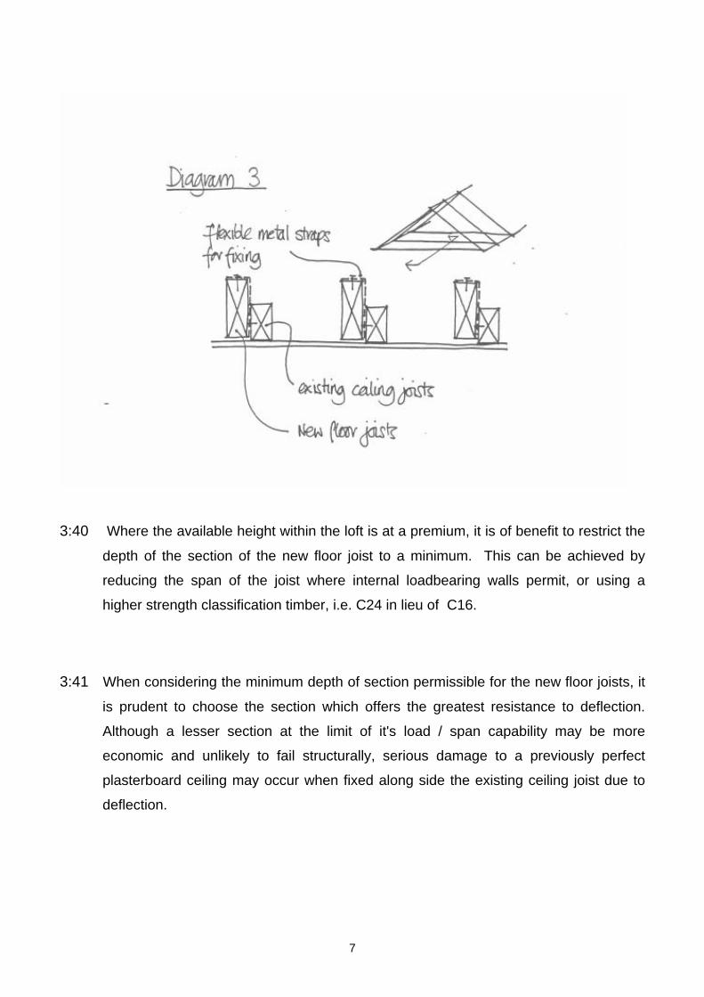
3:30 In the majority of instances the existing ceiling joist member will be inadequate for the
imposed loadings from the new floor construction. A commonly used solution is to
provide new floor joists fixed alongside the existing ceiling joists, spanning from
available loadbearing supports as indicated in Diagram 3. The new floor joist should
also be capable of supporting the existing ceiling particularly where binders are to be
removed. Where the new floor joists are to carry roof load, as in Diagram 2(b), the
floor joists need to be suitably designed.
6
3:40 Where the available height within the loft is at a premium, it is of benefit to restrict the
depth of the section of the new floor joist to a minimum. This can be achieved by
reducing the span of the joist where internal loadbearing walls permit, or using a
higher strength classification timber, i.e. C24 in lieu of C16.
3:41 When considering the minimum depth of section permissible for the new floor joists, it
is prudent to choose the section which offers the greatest resistance to deflection.
Although a lesser section at the limit of it's load / span capability may be more
economic and unlikely to fail structurally, serious damage to a previously perfect
plasterboard ceiling may occur when fixed along side the existing ceiling joist due to
deflection.
7
4:00 FIRE SAFETY
4:10 MEANS OF ESCAPE IN CASE OF FIRE
The addition of a third storey to a dwelling house introduces a greater risk to the
occupants of that storey in the event of a fire occurring on either of the lower floors.
Accordingly the Building Regulations require additional measures to ensure a safe
means of escape is provided within the building.
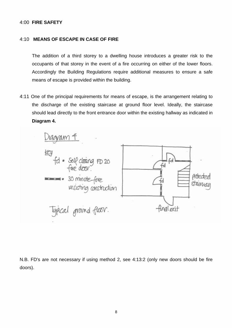
4:11 One of the principal requirements for means of escape, is the arrangement relating to
the discharge of the existing staircase at ground floor level. Ideally, the staircase
should lead directly to the front entrance door within the existing hallway as indicated in
Diagram 4.
N.B. FD's are not necessary if using method 2, see 4:13:2 (only new doors should be fire
doors).
8
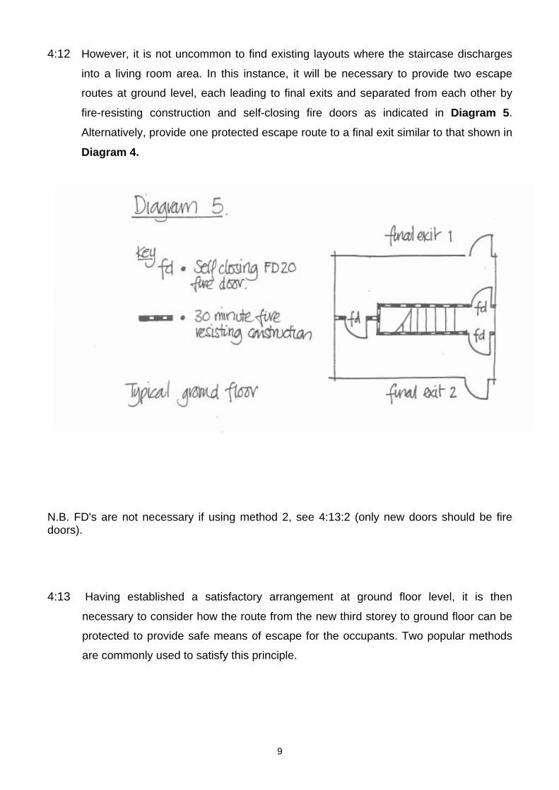
4:12 However, it is not uncommon to find existing layouts where the staircase discharges
into a living room area. In this instance, it will be necessary to provide two escape
routes at ground level, each leading to final exits and separated from each other by
fire-resisting construction and self-closing fire doors as indicated in Diagram 5.
Alternatively, provide one protected escape route to a final exit similar to that shown in
Diagram 4.
N.B. FD's are not necessary if using method 2, see 4:13:2 (only new doors should be fire doors). 4:13 Having established a satisfactory arrangement at ground floor level, it is then
necessary to consider how the route from the new third storey to ground floor can be
protected to provide safe means of escape for the occupants. Two popular methods
are commonly used to satisfy this principle.
9
4:13:1 Method 1. The highest standard of 'passive' safety is achieved by providing a fully
protected enclosure, achieving 30 minutes fire resistance, from the third storey to the
final exit at ground floor level. This will involve assessing the performance of the walls
and partitions to the staircase enclosure in addition to the floor construction, (guidance
on upgrading floors to achieve 30 minutes fire resistance is contained in paragraphs
4:30 - 4:32, "Structural Fire Resistance").
In applying this solution, all doors to habitable rooms leading onto the staircase
enclosure must also achieve 20 minutes fire resistance, by either replacing them with
proprietary fire doors of a FD20 standard (see checklist), or upgrading the existing
doors to achieve a similar performance. In either case, the doors must be fitted with a
positive self-closing device which returns the door into the frame, thus maintaining the
fire protection to the staircase enclosure.
4:13:2 Method 2. A more common approach is to protect the staircase enclosure to a
reduced performance, with the addition of a window or rooflight suitable for escape or
rescue purposes, (guidance on this item is contained in paragraph 4:16).
The reduced performance of the staircase protection allows the retention of existing
doors leading onto the enclosure, provided that they are fitted with positive selfclosing
devices. The walls and partitions to the ground and first floor need to provide 30
minutes fire resistance, and any glazing in the enclosure, including all doors and
fan-lights, should be fire-resisting, (except glazing to a bathroom or w.c.).
10
4:14 In either solution, the new second storey needs to be separated from the rest of the
house by fire-resisting construction, and by the provision of a fire-resisting door (to a
FD20 standard), set in a 30 minute fire-resisting enclosure.
4:15 Consideration must be given to the position of access to the new storey from the first
floor level. Generally, the new stair will rise from the existing landing level and will be
afforded the protection detailed above, however, the situation can arise where, due to
space restrictions, access is more suitably gained from an existing bedroom. In this
instance, it is essential to create a lobby arrangement to remove the necessity to pass
through the bedroom to reach the staircase enclosure.
4:16 Where the provision of an escape window is required, (para 4:13:2), it should be
located to allow access for rescue by ladder from the ground in an emergency
situation. Clearly therefore, suitable pedestrian access must be provided to the point
where the ladder would be set. Consideration must also be given to the position of
existing extensions at ground floor level which may affect the ability to pitch a ladder
to the escape window, (see the 'Checklist' for further commentary).
Acceptable arrangements for dormer windows and rooflights are indicated in Diagram
6 on page 12. Where rooflights are provided, it is essential that an ‘escape’ type unit
is specified and installed which achieves a clear opening of at least 0.33 sq. metres
with minimum clear dimensions of at least 450 mm high and 450mm wide. This is
generally achieved by providing a top-hung unit in lieu of the more common centrally
pivoted unit.
11
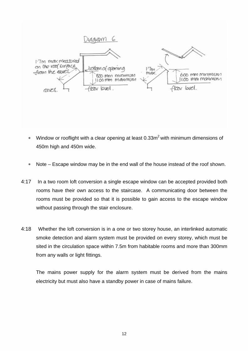
∗ Window or rooflight with a clear opening at least 0.33m2 with minimum dimensions of
450m high and 450m wide.
∗ Note – Escape window may be in the end wall of the house instead of the roof shown.
4:17 In a two room loft conversion a single escape window can be accepted provided both
rooms have their own access to the staircase. A communicating door between the
rooms must be provided so that it is possible to gain access to the escape window
without passing through the stair enclosure.
4:18 Whether the loft conversion is in a one or two storey house, an interlinked automatic
smoke detection and alarm system must be provided on every storey, which must be
sited in the circulation space within 7.5m from habitable rooms and more than 300mm
from any walls or light fittings.
The mains power supply for the alarm system must be derived from the mains
electricity but must also have a standby power in case of mains failure.
12
4:20 SURFACE SPREAD OF FLAME
The Building Regulations control the performance of materials provided for the surface
finish of walls and ceilings. The choice of surface finish can significantly affect the
spread of a fire and it's rate of growth, even though they are not likely to be the
materials first ignited.
4:21 It is not the intention of this booklet to delve into the technicalities of this requirement,
however, it is sufficient to say that the traditional finish of plaster to the internal walls
and ceiling will be adequate. If more unconventional finishes are to be specified,
contact should be made with the Building Control Surveyor.
4:30 STRUCTURAL FIRE RESISTANCE
For the purpose of this requirement, there are two items, which require investigation to
enable a design solution to be achieved.
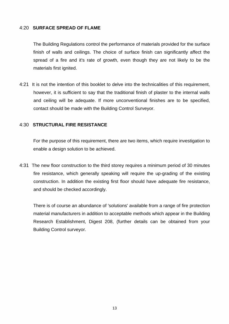
4:31 The new floor construction to the third storey requires a minimum period of 30 minutes
fire resistance, which generally speaking will require the up-grading of the existing
construction. In addition the existing first floor should have adequate fire resistance,
and should be checked accordingly.
There is of course an abundance of 'solutions' available from a range of fire protection
material manufacturers in addition to acceptable methods which appear in the Building
Research Establishment, Digest 208, (further details can be obtained from your
Building Control surveyor.
13
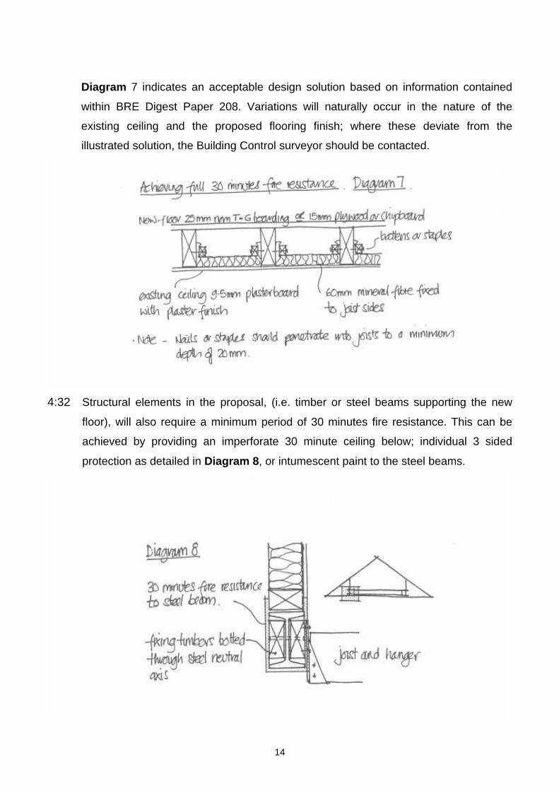
Diagram 7 indicates an acceptable design solution based on information contained
within BRE Digest Paper 208. Variations will naturally occur in the nature of the
existing ceiling and the proposed flooring finish; where these deviate from the
illustrated solution, the Building Control surveyor should be contacted.
4:32 Structural elements in the proposal, (i.e. timber or steel beams supporting the new
floor), will also require a minimum period of 30 minutes fire resistance. This can be
achieved by providing an imperforate 30 minute ceiling below; individual 3 sided
protection as detailed in Diagram 8, or intumescent paint to the steel beams.
14
4:40 EXTERNAL FIRE SPREAD
There are several considerations which need to be taken into account in respect of loft
conversions to satisfy this requirement, which are generally more onerous when
opting for a dormer, rather than a rooflight.
4:41 The roof covering of new dormers should be specified to give adequate protection
against the spread of fire over them. For practical purposes, the re-use of the existing
roof covering of natural or fibre reinforced cement slate, or, concrete or clay tile, will
satisfy the requirement.
Additional consideration should be given where a new flat roof is proposed. Where a
flat roof covered with a built-up bitumen felt system is specified, the performance will
be satisfactory if the surface finish is bitumen-bonded, stone chippings to a depth of at
least 12.5mm.
4:42 Space separation between buildings is important to restrict the chance of fire
spreading across an open space between buildings. Where such part of the external
wall does not achieve the relevant period of fire resistance, in this case 30 minutes. or
has a combustible surface material, they are referred to as 'unprotected areas'.
For the purpose of dormer installations within domestic loft conversions, the
relationship between 'unprotected areas' and the boundary line of the property,
becomes critical when the distance is less than lm. This might occur when the dormer
cheek, (the side wall of a dormer), or the window, faces the boundary.
15
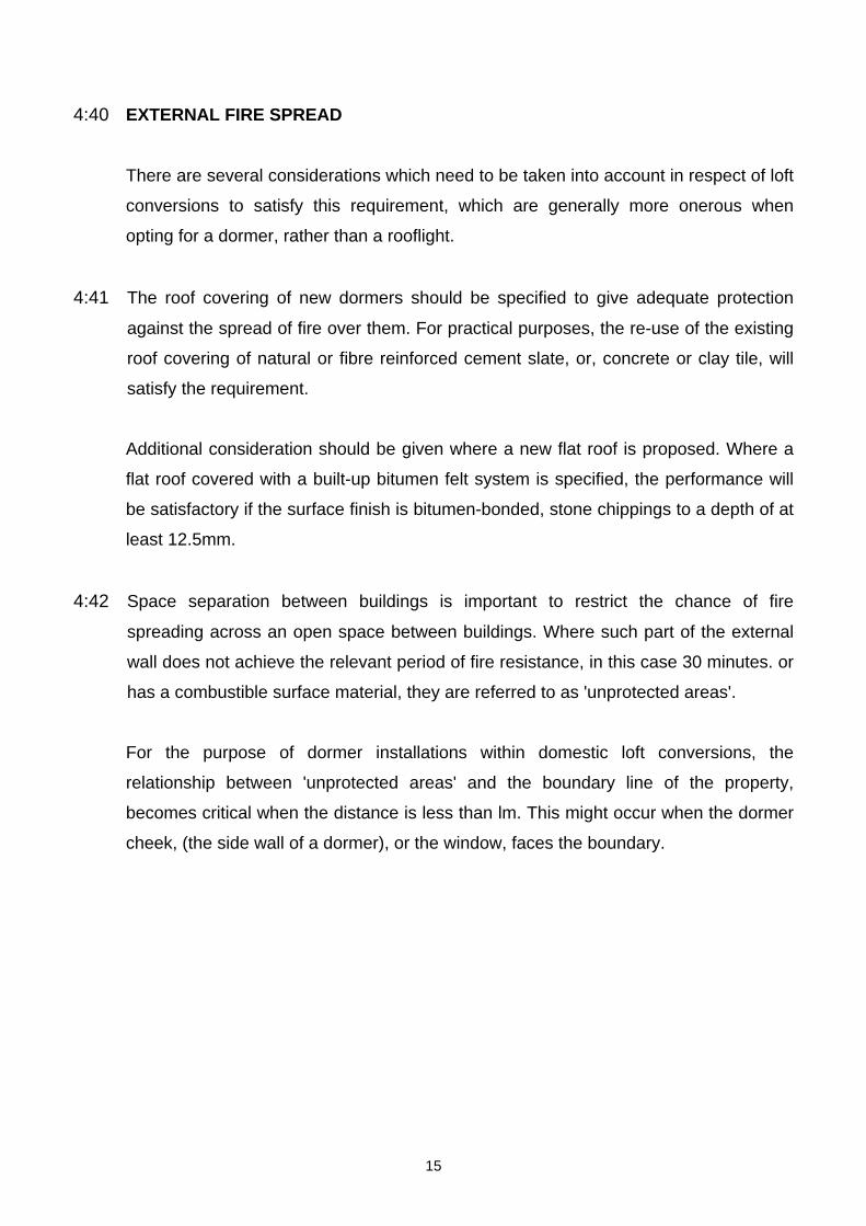
A wall is treated as facing a boundary if it is parallel with it, or makes an angle with it of 80° or
less, as indicated in Diagram 9
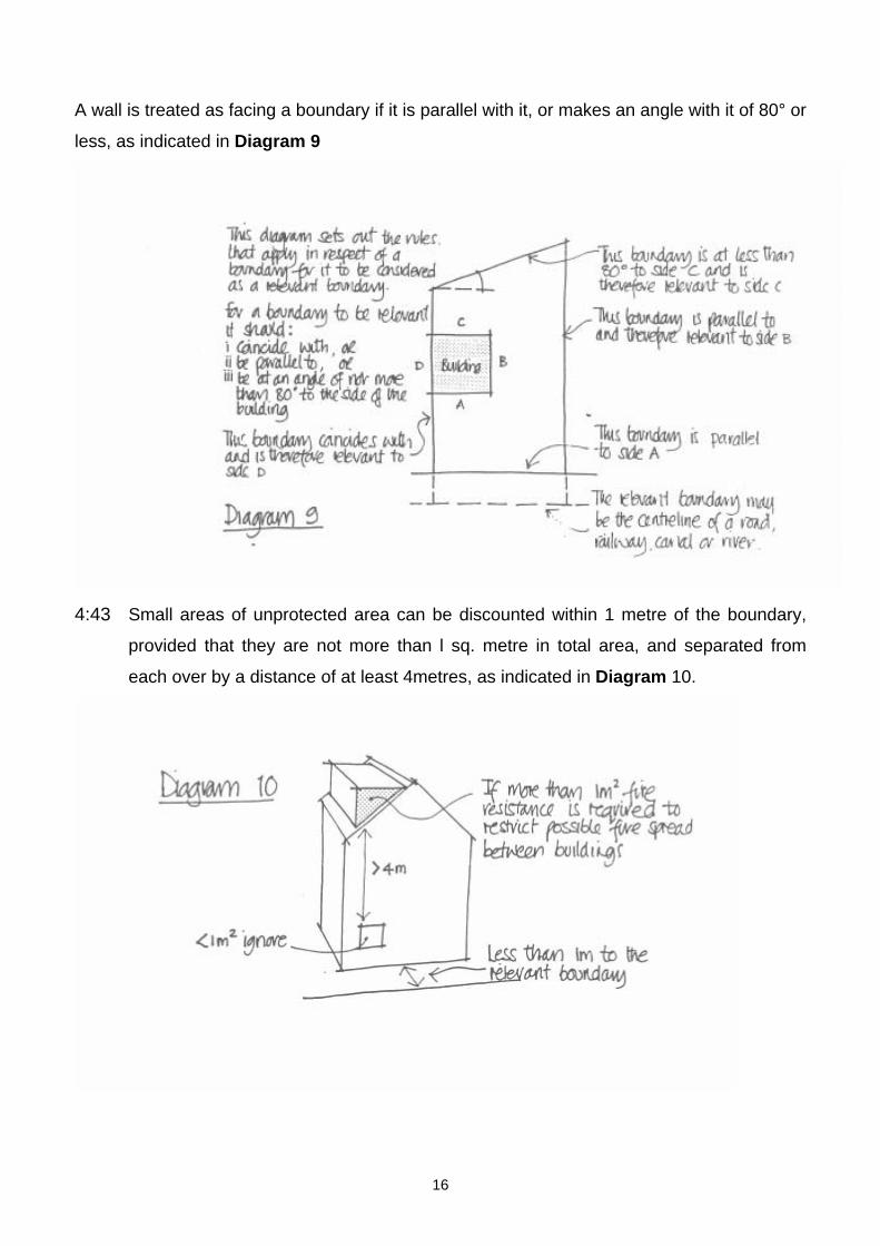
4:43 Small areas of unprotected area can be discounted within 1 metre of the boundary,
provided that they are not more than l sq. metre in total area, and separated from
each over by a distance of at least 4metres, as indicated in Diagram 10.
16
4:44 If an external wall has the appropriate fire resistance, (30 minutes in this instance), but
has a combustible material more than l mm thick as it's external surface, then that wall
is counted as an unprotected area amounting to half the actual area of the
combustible surface material. For example, if a dormer cheek of 2m2, within l metre of
the boundary, is clad with timber boarding, the unprotected area is expressed as 2 x
50% = lm2. This would therefore be satisfactory, see 4.43.
4:45 With regard to the construction of the external wall, or dormer cheek, the element
must achieve the relevant period of fire resistance (30 minutes), particularly when
within l metre of the boundary, when it will require fire resistance from both sides.
This is most important where the dormer cheek is framed in timber studwork, and will
require the addition of a fire resistant board within the cheek construction.
For example, if a dormer cheek within I metre of the boundary is clad externally with
slates, concrete or clay tiles as previously mentioned in 4:41, it will also require the
use of a 30 minute fire resistant board both internally and externally in order to protect
the studwork structure.
5:00 VENTILATION
17
5:10 ROOM VENTILATION
The formation of a habitable room requires the provision of both 'rapid ventilation', (an
opening window), and 'background ventilation'. In addition, if the conversion involves a
shower or bath facility, then 'mechanical ventilation' will also be required.
The following simplified guidance indicates suitable provisions for meeting the
requirements, however, other methods are available, i.e.; Passive Stack Ventilation
(further details are available from your Building Control surveyor.)
5:11 Habitable rooms, such as Bedrooms and Living Rooms, require rapid ventilation to an
area equivalent to 1/20th of the floor area, i.e.; Floor area 20m2 = Rapid vent opening
lm2, and background ventilation of 8,000mm2.
5:12 If a bathroom is proposed, then mechanical ventilation to the external air is required to
achieve an extract rate of at least 15 litres per second, with a 15 minute overrun
facility if the bathroom does not contain an opening window.
If a window is available, mechanical extract is still required, but in lieu of the fan
overrun, an opening window (no minimum size) and background ventilation of
4,000mm2, can be provided.
5:20 ROOF VENTILATION
18
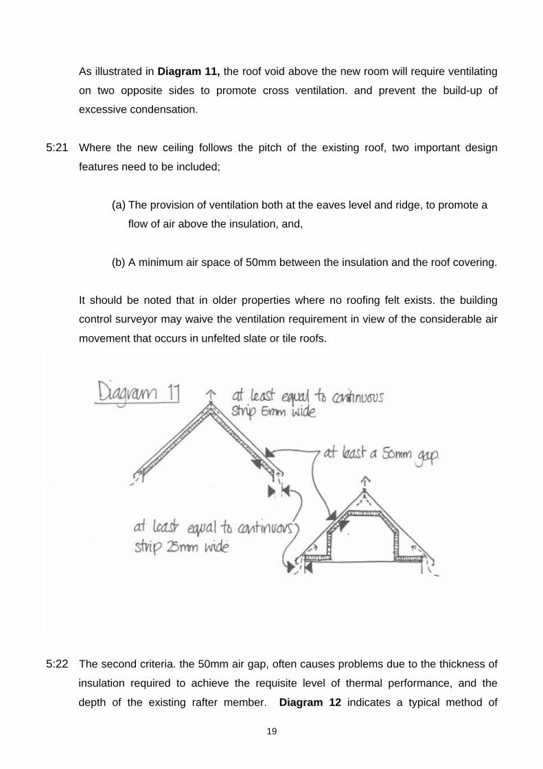
As illustrated in Diagram 11, the roof void above the new room will require ventilating
on two opposite sides to promote cross ventilation. and prevent the build-up of
excessive condensation.
5:21 Where the new ceiling follows the pitch of the existing roof, two important design
features need to be included;
(a) The provision of ventilation both at the eaves level and ridge, to promote a
flow of air above the insulation, and,
(b) A minimum air space of 50mm between the insulation and the roof covering.
It should be noted that in older properties where no roofing felt exists. the building
control surveyor may waive the ventilation requirement in view of the considerable air
movement that occurs in unfelted slate or tile roofs.
5:22 The second criteria. the 50mm air gap, often causes problems due to the thickness of
insulation required to achieve the requisite level of thermal performance, and the
depth of the existing rafter member. Diagram 12 indicates a typical method of
19
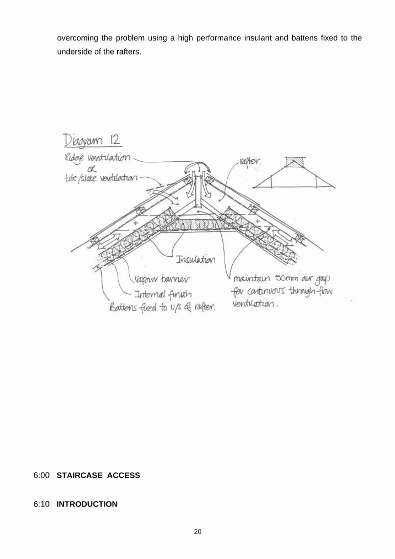
overcoming the problem using a high performance insulant and battens fixed to the
underside of the rafters.
6:00 STAIRCASE ACCESS
6:10 INTRODUCTION
20
When a new storey is proposed within a residential unit, a permanent access must be
provided, which ideally will take the form of a traditional staircase similar to that which
provides access from ground to first floor. In certain instances, access can be
arranged via a fixed ladder or alternating tread stair, subject to restrictions, which will
be discussed later.
6:20 TRADITIONAL STAIRCASE
If a traditional flight is proposed, the parameters for the rise, going and pitch of the
flight are as follows; Max Rise 220mm - Min Going 220mrn - Max Pitch 42°.
The normal relationship between the dimensions of the rise and going is that twice the
rise plus the going (2R + G) should be between 550rnm and 700mm.
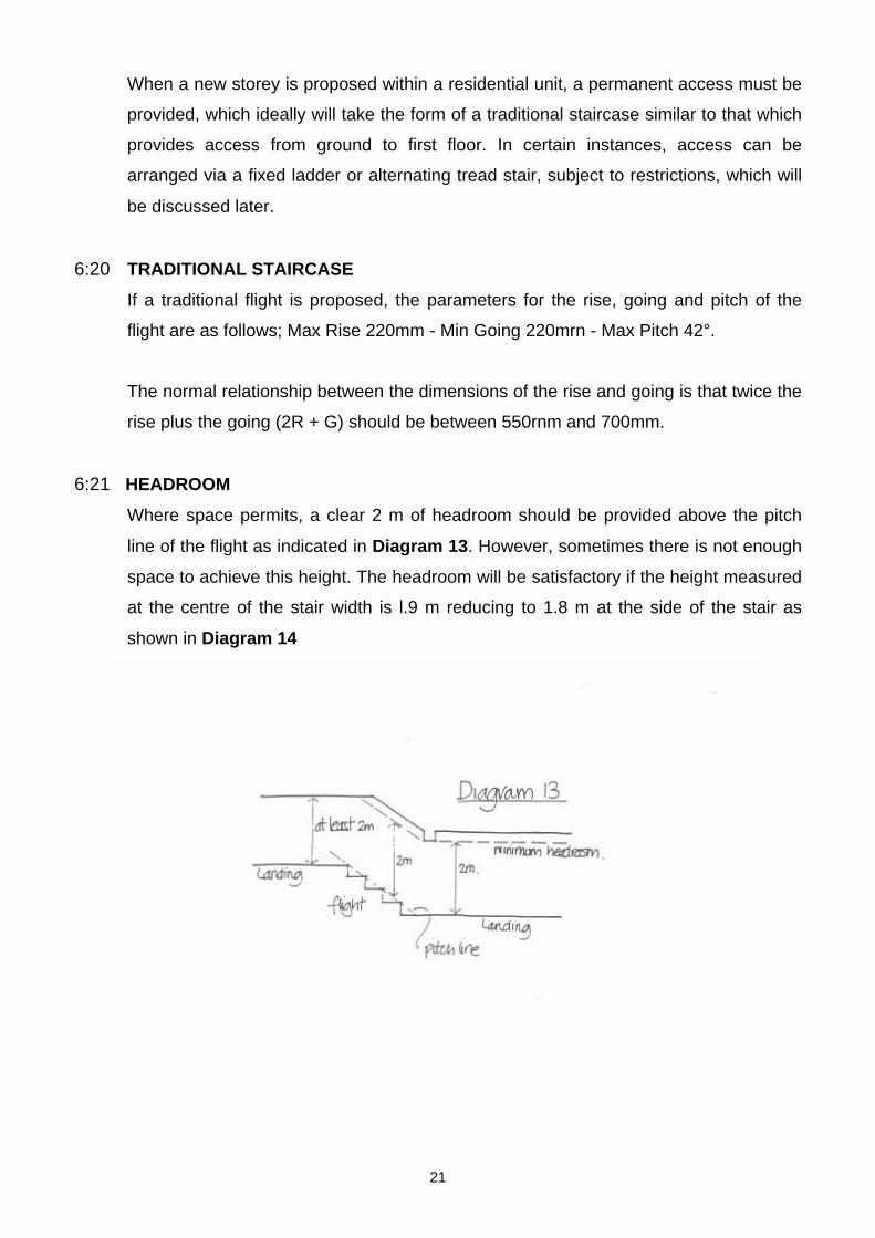
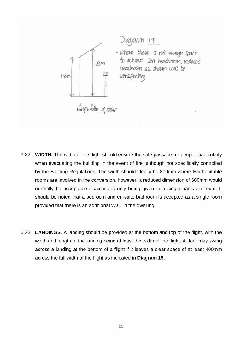
6:21 HEADROOM
Where space permits, a clear 2 m of headroom should be provided above the pitch
line of the flight as indicated in Diagram 13. However, sometimes there is not enough
space to achieve this height. The headroom will be satisfactory if the height measured
at the centre of the stair width is l.9 m reducing to 1.8 m at the side of the stair as
shown in Diagram 14
21
6:22 WIDTH. The width of the flight should ensure the safe passage for people, particularly
when evacuating the building in the event of fire, although not specifically controlled
by the Building Regulations. The width should ideally be 800mm where two habitable
rooms are involved in the conversion, however, a reduced dimension of 600mm would
normally be acceptable if access is only being given to a single habitable room. It
should be noted that a bedroom and en-suite bathroom is accepted as a single room
provided that there is an additional W.C. in the dwelling.
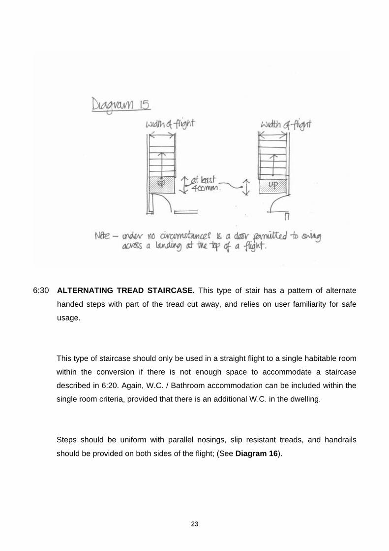
6:23 LANDINGS. A landing should be provided at the bottom and top of the flight, with the
width and length of the landing being at least the width of the flight. A door may swing
across a landing at the bottom of a flight if it leaves a clear space of at least 400mm
across the full width of the flight as indicated in Diagram 15.
22
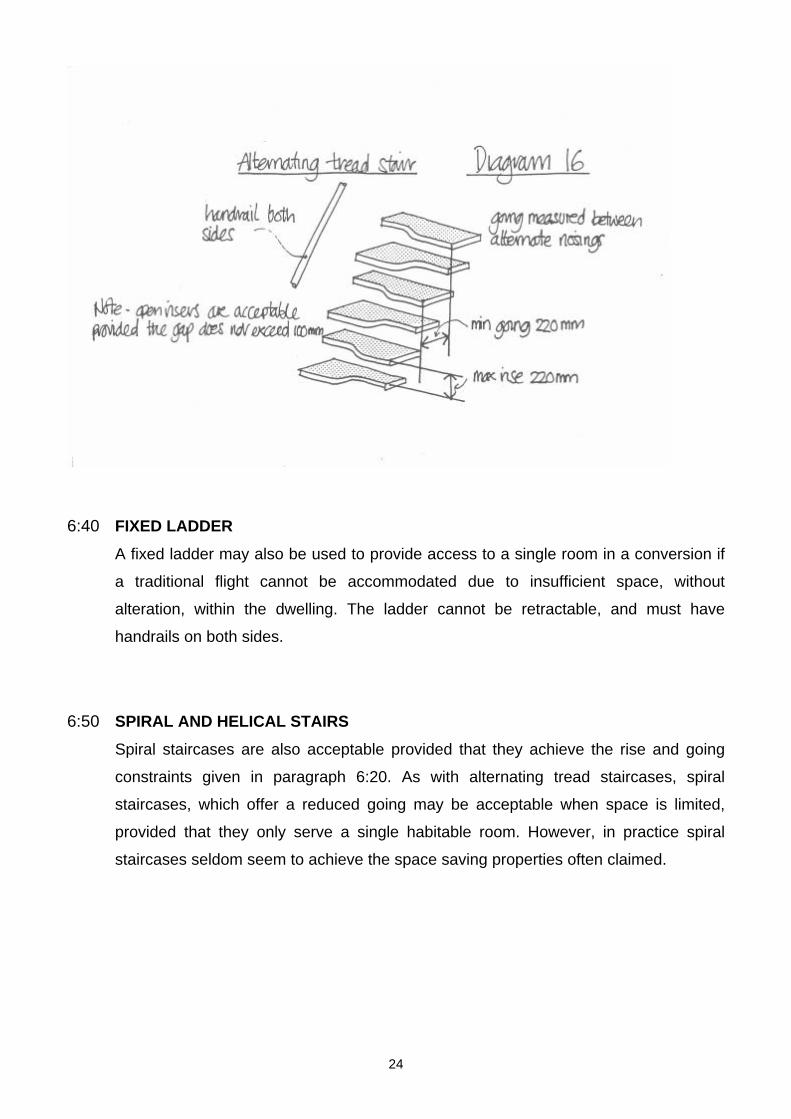
6:30 ALTERNATING TREAD STAIRCASE. This type of stair has a pattern of alternate
handed steps with part of the tread cut away, and relies on user familiarity for safe
usage.
This type of staircase should only be used in a straight flight to a single habitable room
within the conversion if there is not enough space to accommodate a staircase
described in 6:20. Again, W.C. / Bathroom accommodation can be included within the
single room criteria, provided that there is an additional W.C. in the dwelling.
Steps should be uniform with parallel nosings, slip resistant treads, and handrails
should be provided on both sides of the flight; (See Diagram 16).
23
6:40 FIXED LADDER
A fixed ladder may also be used to provide access to a single room in a conversion if
a traditional flight cannot be accommodated due to insufficient space, without
alteration, within the dwelling. The ladder cannot be retractable, and must have
handrails on both sides.
6:50 SPIRAL AND HELICAL STAIRS
Spiral staircases are also acceptable provided that they achieve the rise and going
constraints given in paragraph 6:20. As with alternating tread staircases, spiral
staircases, which offer a reduced going may be acceptable when space is limited,
provided that they only serve a single habitable room. However, in practice spiral
staircases seldom seem to achieve the space saving properties often claimed.
24
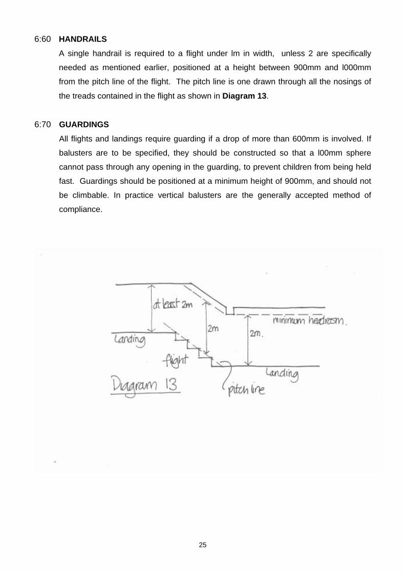
6:60 HANDRAILS
A single handrail is required to a flight under lm in width, unless 2 are specifically
needed as mentioned earlier, positioned at a height between 900mm and l000mm
from the pitch line of the flight. The pitch line is one drawn through all the nosings of
the treads contained in the flight as shown in Diagram 13.
6:70 GUARDINGS
All flights and landings require guarding if a drop of more than 600mm is involved. If
balusters are to be specified, they should be constructed so that a l00mm sphere
cannot pass through any opening in the guarding, to prevent children from being held
fast. Guardings should be positioned at a minimum height of 900mm, and should not
be climbable. In practice vertical balusters are the generally accepted method of
compliance.
25
7:00 THERMAL INSULATION
7:10 INTRODUCTION
Provision must be made for insulating the roof, including the pitched section, and
the new internal walls within the conversion to prevent heat loss.
7:20 ROOF INSULATION.
As mentioned in paragraph 5.22, the use of a high performance insulant to the pitched
roof section allows greater flexibility in providing effective cross-ventilation, and also
increased height within the room.
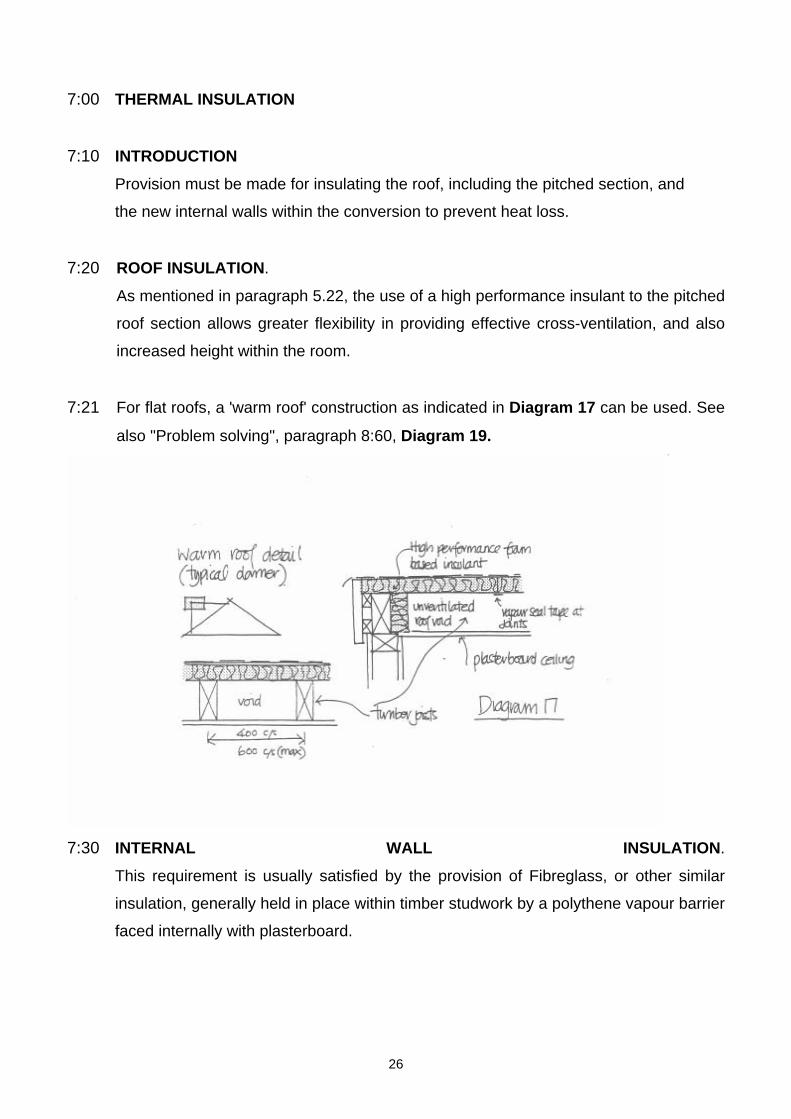
7:21 For flat roofs, a 'warm roof' construction as indicated in Diagram 17 can be used. See
also "Problem solving", paragraph 8:60, Diagram 19.
7:30 INTERNAL WALL INSULATION.
This requirement is usually satisfied by the provision of Fibreglass, or other similar
insulation, generally held in place within timber studwork by a polythene vapour barrier
faced internally with plasterboard.
26
8:00 ELECTRICAL SAFETY
From the 1st of January 2005, any new fixed electrical installations for domestic
premises will be required to be designed and installed in accordance with the
Building Regulations, Approved Document P & British Standards 7671. (Further
details can be obtained from your Local Building Control Authority).
NOTE:
If you are employing the services of an electrician registered to a self certifying
body, then Building Regulation Approval is not required.
27
9:00 TYPICAL PROBLEMS AND SOLUTIONS
9:10 PROBLEM:
Cill height of the roof window exceeds the 1100mm indicated in the Approved
Document guidance.
SOLUTION:
A fixed step may be constructed below the window opening to bring the cill height
within the 1100mm maximum. See Diagram 6
9:20 PROBLEM:
Insufficient headroom exists over the landing at the top of the loft staircase.
SOLUTION:
The obvious answer to this problem is to construct a small dormer window, but a far
more economical solution which will gain in the region of 200mm headroom, is to
install a roof window over the landing area. This will also provide natural light to the
staircase, but will need to be fixed shut if the central pivot type is used.
9:30 PROBLEM:
The existing fascia board is fixed directly against the wall providing no soffit for eaves
ventilation.
SOLUTION: Provide an adequate number of slate or tile ventilators, allowing an
interchange of air to the triangular roof void formed by the rafters, ceiling joists and vertical stud wall. Note, that the roofing felt must be penetrated below each vent.
9:40 PROBLEM:
28
A I00mm diameter drainage vent pipe is obstructed by the structure.
SOLUTION:
It may be possible to use an air admittance valve to solve this problem making it
possible to terminate the vent pipe within the roof space therefore avoiding the
constriction of space. However, in some instances these valves are not permitted and
in such cases it is possible for the vent pipe diameter to be reduced to 50mm in order
to negotiate the restricted area. The term vent pipe applies to the dry section of the
pipe only.
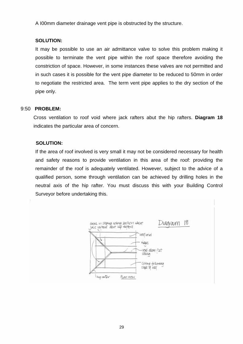
9:50 PROBLEM:
Cross ventilation to roof void where jack rafters abut the hip rafters. Diagram 18
indicates the particular area of concern.
SOLUTION:
If the area of roof involved is very small it may not be considered necessary for health
and safety reasons to provide ventilation in this area of the roof: providing the
remainder of the roof is adequately ventilated. However, subject to the advice of a
qualified person, some through ventilation can be achieved by drilling holes in the
neutral axis of the hip rafter. You must discuss this with your Building Control
Surveyor before undertaking this.
29
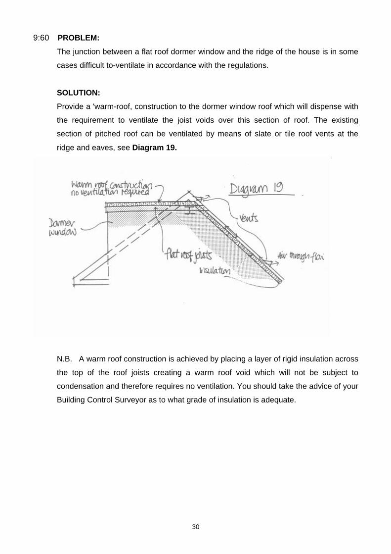
9:60 PROBLEM:
The junction between a flat roof dormer window and the ridge of the house is in some
cases difficult to-ventilate in accordance with the regulations.
SOLUTION:
Provide a 'warm-roof, construction to the dormer window roof which will dispense with
the requirement to ventilate the joist voids over this section of roof. The existing
section of pitched roof can be ventilated by means of slate or tile roof vents at the
ridge and eaves, see Diagram 19.
N.B. A warm roof construction is achieved by placing a layer of rigid insulation across
the top of the roof joists creating a warm roof void which will not be subject to
condensation and therefore requires no ventilation. You should take the advice of your
Building Control Surveyor as to what grade of insulation is adequate.
30

9:70 PROBLEM:
A steel or timber beam is often required at the ridge level but the point of bearing
coincides with the chimney flue.
SOLUTION:
This situation often occurs in large dormer window designs where a ridge beam is
normally a structural requirement. Reference to the checklist item on chimney flues
will reveal that combustible material and metal fixings should be separated from a
brick or blockwork chimney and this requirement generally precludes an easy solution
to the problem of beam support.
An. answer to this difficulty can be found if the property possesses a central
loadbearing masonry wall on which a suitable vertical metal or timber post can bear.
This post can then accept the load from the ridge beam provided it is separated from
the flue in accordance with the Approved Document guidance, and forms part of a
studwork wall suitably nogged and fixed at both rafter and new floor level. This will
ensure lateral stability is maintained within the structure.
We suggest that a structural engineer be consulted for any calculations that may be
required. N.B. It should be noted that a beam supporting the roof structure only, (i.e.:-
at ridge level), does not require fire proofing to the half hour standard.
31
10:00 CHECKLIST
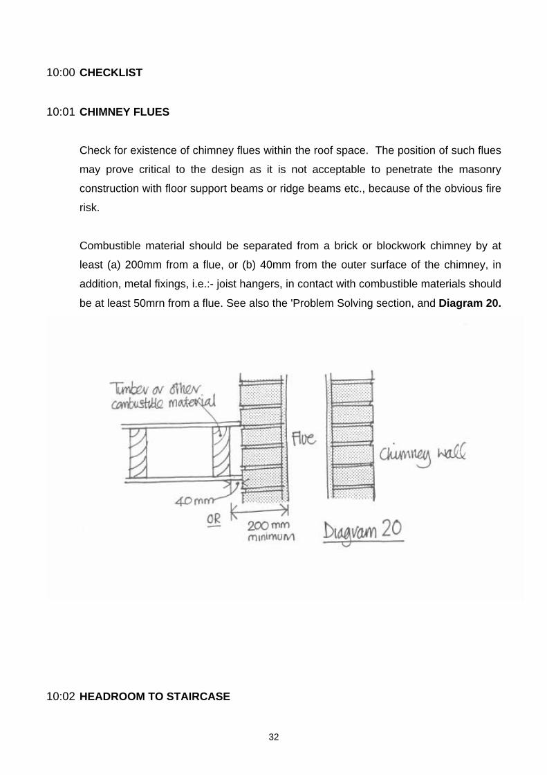
10:01 CHIMNEY FLUES
Check for existence of chimney flues within the roof space. The position of such flues
may prove critical to the design as it is not acceptable to penetrate the masonry
construction with floor support beams or ridge beams etc., because of the obvious fire
risk.
Combustible material should be separated from a brick or blockwork chimney by at
least (a) 200mm from a flue, or (b) 40mm from the outer surface of the chimney, in
addition, metal fixings, i.e.:- joist hangers, in contact with combustible materials should
be at least 50mrn from a flue. See also the 'Problem Solving section, and Diagram 20.
10:02 HEADROOM TO STAIRCASE
32
Check that sufficient headroom exists over the area designated for the new stair (see
Diagram 14), and refer to 'Problem Solving' for a possible solution if headroom is
limited.
10:03 THROUGH ROOMS
Check whether any load-bearing walls at ground floor level have been removed to
create a 'through-room' situation. Where this is the case it will be necessary to
ascertain the type of lintel/beam used to form the opening in a loadbearing wall in
order to establish it's ability to cope with any extra loading imposed by the loft
conversion. The Local Authority will normally request calculations.
10:04 CONSERVATORIES
Check whether a conservatory, or pitched roof extension exists below the point where
an escape window is to be provided. This is unacceptable for two reasons;
10:04:1 The conservatory / pitched roof extension could restrict the safe use of ladders for
escape purposes.
10:04:2 A translucent sheet roof is incapable of safely supporting the weight of any person
using it for escape purposes. It should be noted that flat roof extensions may be
acceptable in this situation.
10:05 SOIL & VENT PIPES
Check that any new or existing soil and vent pipe will terminate at least 900mm
above any opening into the building, which is within 3.0m of the pipe.
10:06 BAY WINDOWS
33
Check existing lintels over bay windows to ensure that they are capable of supporting
any extra loading imposed from floor joists etc. Calculations will normally be required
by the Building Control Surveyor if any doubt exists, and replacement with an
approved lintel requested if proved unsatisfactory.
10:07 SLIDING HINGES
Where an escape window is required, (see method two, para 4.16), ensure that this
window is not fitted with the 'slide-across' type of hinge. Although this facilitates easy
cleaning, it may also reduce the effective opening size of the window below the
minimum of at least 0.33m2 (clear area) and at least 450mm high and 450mm wide,
indicated in the Approved Document guidance.
10:08 ALIGNMENT OF WALLS
Check for alignment of load-bearing walls, as it is often the case that walls are offset
between floor levels resulting in existing floor joists taking considerable loads from the
wall above bearing upon them.
In this situation it will be necessary to ascertain the ability of the existing joists to
support any additional loading imposed upon them by the loft conversion.
Calculations will normally be requested by the Local Authority to prove the adequacy
of the structure.
10:09 PARTY WALLS
34
Check the construction of party walls at roof level. Cavity walls or 225mrn solid walls
usually present few problems, but 100rnrn thick single skin walls are problematical
when beams or floor joists have to bear upon them. Design solutions, which avoid
penetration of such walls, should be adopted. Fireproofing at roof level and at beam
bearings should also be addressed.
10:10 SLIDING DOORS
Check for the existence of sliding doors to habitable rooms opening off the staircase
enclosure. It is difficult to install self-closing devices to sliding doors and unacceptable
gaps invariably exist between door and frame. These doors are normally replaced by
traditional hinged doors, but care must be taken to ascertain that space exists to
accept the door swing.
10:11 PLASTIC / NYLON HINGES
It is not acceptable to use plastic or nylon type hinges and door furniture in
conjunction with fire doors.
10:12 MINERAL FIBRE / FIBREGLASS QUlLTS
Check that the quilt specified or used on site for achieving a full 30 minute fire
resistance to the new floor is mineral fibre and not combustible fibreglass; the former
being non-combustible and therefore fire retardant, the latter being highly inflammable
in some product forms, see Diagram 7.
10:13 RIGID BOARD INSULATION
35
Check that the rigid board insulation supplied for use in the rafter voids is a high
performance foam based insulant and not the cheaper white polystyrene normally
used for cavity wall insulation. The former is twice as efficient thermally and allows
increased height within the room. If in doubt, contact your Building Control Surveyor
for advice before installation. Thermal efficiency requirements change regularly,
please ask for the up to date ‘U Value’ requirement.
10:14 FD20 SPECIFICATION FIRE DOOR
A FD20 fire-resisting door rated to BS 476: Part 22, can be identified by 'core plugs'
set into the lipping of the door. If the plug has a red core within a white background,
an intumescent strip will be required in either the door or frame to achieve the rating.
However, if the door is identified by a blue core within a white background, then the
additional provision of intumescent is not required to satisfy a FD20 performance.
Other forms of identification are also being introduced, if in doubt ask your Building
Control Surveyor. Two hinges would normally be provided for this rating in addition to
a positive self-closing device.
36