Loess Hills Stormwater Best Management Practices …...Loess Hills Stormwater . Best Management...
45
Loess Hills Stormwater Best Management Practices Guidance Manual Prepared for: Golden Hills Resources and Conservation Development, Inc. 712 South Highway 6 P.O. Box 189 Oakland, IA 51560-0189 Prepared by: HDR Engineering 301 South 13 th Street, Suite 601 Lincoln, NE 68508-2532 and The Schemmer Associates 1044 North 115 th Street, Suite 300 Omaha. NE 68154-4436
Transcript of Loess Hills Stormwater Best Management Practices …...Loess Hills Stormwater . Best Management...
Loess Hills Stormwater Best Management Practices
Guidance Manual
Prepared for: Golden Hills Resources and
Conservation Development, Inc. 712 South Highway 6
P.O. Box 189 Oakland, IA 51560-0189
Prepared by:
HDR Engineering 301 South 13th Street, Suite 601
Lincoln, NE 68508-2532 and
The Schemmer Associates 1044 North 115th Street, Suite 300
Omaha. NE 68154-4436

Acknowledgements STEERING COMMITTEE
Shirley Frederiksen, Executive Director, Golden Hills RC&D Joni Sell, Mills County SWCD Danelle Schmielau, West Pottawattamie SWCD Rich Maaske. West Pottawattamie SWC Kay Mocha, Pottawattamie County Planning & Development Department John Rasmussen, Pottawattamie County Engineer Kevin Mayberry, Mills County Engineer Shelly Jager, Key Real Estate Jerry Duggan, Duggan Homes Kevin Seevers, West Pottawattamie SWCD Terry Smith, HGM Associates Melvyn Houser, Pottawattamie Board of Supervisors
CONSULTANT TEAM John Cambridge, HDR Engineering Brian Leaders, The Schemmer Associates Paul Gonzales, The Schemmer Associates Loras Klostermann, The Schemmer Associates
Loess Hills Stormwater BMP Guidance Manual
Table of Contents
Purpose of the Loess Hills Stormwater BMP Guidance Manual ...................................... 1 A discussion of loess soils and stormwater infiltration practices ................................... 4
Definitions ....................................................................................................................... 6 Stormwater Best Management Practices ....................................................................... 15
BMP Reference 2E-2 Infiltration Trenches or Dry Well Seepage Pits......................... 17 BMP Reference 2E-3 Infiltration Basin ....................................................................... 18 BMP Reference 2E-4 Bioretention Systems............................................................... 19 BMP Reference 2E-X Retentive Grading and Infiltration Berms ................................. 20 BMP Reference 2E-7 Soils Testing Requirements for Infiltration Practices ................ 21 BMP Reference 2E-7 Soils Testing Requirements for Soil Fill Embankment
Construction ........................................................................... 23 BMP Reference 2F-2 Surface and Perimeter Sand Filters ......................................... 24 BMP Reference 2F-3 Underground Sand Filter ......................................................... 25 BMP Reference 2G-2 Dry Detention .......................................................................... 26 BMP Reference 2G-3 Wet Pond Retention Basin ...................................................... 27 BMP Reference 2H-2 Constructed Wetlands ............................................................. 28 BMP Reference 2I-2 Grassed Swales........................................................................ 29 BMP Reference 2I-3 Dry and Wet Swales ................................................................. 30 BMP Reference 2I-4 Grassed Vegetated Filter Strips ................................................ 31 BMP Reference 2J-4 Pervious Pavement .................................................................. 32 BMP Reference 2J-4 Pervious Pavement (continued) ............................................... 33 BMP Reference 2K-1Mechanical System .................................................................. 34 BMP Reference 2L-1Chemical Treatment for Turbidity Removal ............................... 35 BMP Reference 2M-1 General Information for Storm Sewer Design .......................... 36 BMP Reference 2M-1 General Information for Storm Sewer Design (continued) ....... 37 BMP Reference 2N-1 General Information for Design of Culverts .............................. 38 BMP Reference 2O-1 Open Channel Flow ................................................................ 39 BMP Reference 2O-1 Open Channel Flow (continued) .............................................. 40
References .................................................................................................................... 41 Photography Credits...................................................................................................... 41
Cover Photo credit: Golden Hills RC&D

Loess Hills Stormwater BMP Guidance Manual

Loess Hills Stormwater BMP Guidance Manual
Version 1; October, 23 2008 Page 1 of 41
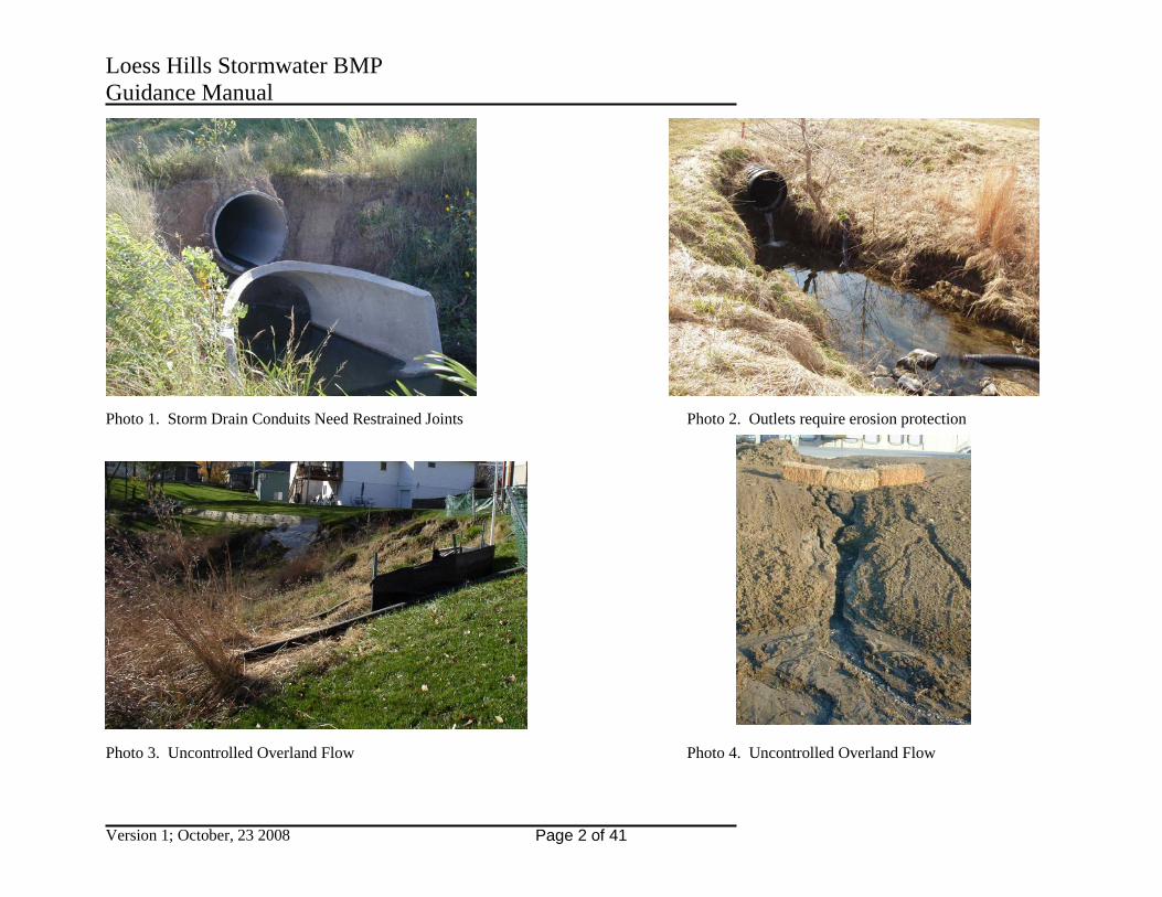
Purpose of the Loess Hills Stormwater BMP Guidance Manual This document is designed to be used as supplemental guidance for the design and use of low impact development best management practices in the Loess Hills area of Iowa. It is not a replacement of the Iowa Statewide Urban Design And Specifications (SUDAS) Iowa Statewide Urban Design Standards Manual. This document presents specific design recommendations and investigations of loess soil characteristics for the use of low impact development best management practices. Loess soils are not necessarily unique, as they cover tens of thousands of square miles across the Midwest. The loess soils are composed of wind deposited silts with high quartz content from Pleistocene era river valleys. In western Iowa, there existed just the right combination of climate, abundant outwash material, and valley width for unusually thick deposits to accumulate (source: Geology of the Loess Hills, Proceedings of the Iowa Academy of Science, 1986, Bettis, etal). The exceptional thickness, uniform grain size, permeability, easy erodibility, and propensity to stand in near-vertical faces explains much about the striking topography and the interest it holds for geologists, engineers, and past as well as present inhabitants (source: ibid). Striking topography as long created a desire for people to live among the loess hills, as documented prehistoric dwelling sites are common. Loess soil does have unique characteristics requiring special attention be given during planning, design and construction of developments to avoid undesirable outcomes. These characteristics must be identified and addressed by thorough geotechnical investigation, soils analysis and foundation design. Failure to adequately investigate and obtain proper design recommendations could result in loess soil failures resulting from low strength, settlement, and/or excessive erosion. See the photographs on the following page. The loess hills also provide unique habitat for vegetation, it is the western most range of the eastern deciduous species, and the eastern most range of the western plains species, making this an area of significant biological crossroads. This area harbors over 20,000 acres of remnant prairie representing about 75% of Iowa's remaining prairie heritage, of which 99.9% is already lost (source: Golden Hills RC&D Website). Communities will continue to feel the pressure to grow and developers and their planners, engineers, and contractors need tools to properly plan, design, and build subdivisions to meet the demand for more housing. Low Impact Development (LID) is an ideal approach for the inevitable urbanization that is occurring (and will continue to occur) in the loess hills. As the land use changes from undeveloped or agricultural to developed, impervious surfaces create increased amounts of stormwater runoff during rainfall events, disrupting the natural hydrologic cycle. Without stormwater management, these conditions erode stream channels and prevent groundwater recharge. Parking lots, roadways, rooftops, and other impervious surfaces increase the pollution levels and temperature of stormwater that is transported to streams, rivers, and groundwater resources.
Loess Hills Stormwater BMP Guidance Manual
Version 1; October, 23 2008 Page 2 of 41
Photo 1. Storm Drain Conduits Need Restrained Joints Photo 2. Outlets require erosion protection Photo 3. Uncontrolled Overland Flow Photo 4. Uncontrolled Overland Flow

Loess Hills Stormwater BMP Guidance Manual
Version 1; October, 23 2008 Page 3 of 41
LID concepts include; identification of areas that should not be disturbed such as wetlands, steep slopes, and prairie areas; clustering development to reduce the footprint and infrastructure needs; minimizing impervious area; and building stormwater best management practices to compensate for the remaining impervious area. Implementing the requirements in this manual will help protect the Loess Hills water resources, which in turn will provide great benefit to human health, fish and wildlife habitat, recreational resources, and drinking water. Stormwater management is also critical in terms of protecting the Loess Hills sanitary and stormwater infrastructure. Increased runoff contributes to combined sewer overflows (CSOs) and basement sewer backups. Implementing onsite infiltration and flow control measures will conserve the existing and future conveyance capacity of storm sewers and combined sewers. Increased flow concentration will result in higher erosive forces on previously stable drainage structures. Strategies for meeting the requirements in this manual depend on a number of site factors, including infiltration capacity, available infrastructure, proposed development plans, and the drainage basin the proposed development is in. The applicant’s ability to effectively use the design standards in this manual depends on a demonstrated understanding of the development site’s ecology and of the potential upstream, downstream, groundwater impacts resulting from stormwater management improvements. The guidance provided in this manual are intended to supplement the criteria provided in the ISWMM for the planning, design, construction, operation and maintenance of stormwater best management practices on loess soils in western Iowa, to make site-specific improvements to properties across the Loess Hills and to comprehensively manage stormwater by watershed. Stormwater management is critical to maintaining and enhancing the community’s livability and improving watershed health. The Loess Hills Stormwater BMP Guidance Manual allows the communities to protect both watershed resources and infrastructure investments with every land improvement. As each development and redevelopment project meets the requirements of this manual, it will contribute to achieving these important area-wide goals

Loess Hills Stormwater BMP Guidance Manual
Version 1; October, 23 2008 Page 4 of 41
A discussion of loess soils and stormwater infiltration practices Most of the stormwater infiltration BMP’s work in very similar manner. Each requires that the soil accept water by percolation. However, water must first pass into the soil by infiltration. It is noted that runoff water is not clean, containing silty soil particles and organic materials. The application of runoff water to a surface causes the non-water materials to be left on the soil interface and these soil and organic materials will quickly form a natural barrier to infiltration. This natural liner affect allows area lakes to hold water as the groundwater level or an area river level drops below the base of the impoundment and has been studied on area lakes, in particular Carter Lake in Iowa. Maintenance of each of these BMP’s will need to include cleaning of the natural liner materials from the soil surface to optimize infiltration and absorption. Without ground surface maintenance an infiltration bed becomes an evaporation pond. Absorption of water into soil changes with time and season. Percolation tests allow a physical measure of the ability of soil to absorb water at a certain time and at the insitu water content at the time of the test. Weather trends at the time of the test will affect the percolation rate even though an attempt to saturate a small area around the test holes is attempted by standard percolation test methods. These BMP’s will be taxed during wet weather cycles as the soil achieves a higher degree of saturation in the area of the infiltration BMP and the area soils also achieve a higher degree of saturation through natural absorption. These BMP’s will be expected to allow absorption of the greatest amounts of water during wet weather periods, at times when the soil water content and degree of saturation are greatest. Immediately after periods of drought, there may be a short time period when the soil will not accept water absorption due to a “vapor lock” affect. This is similar to the affect sometimes found on a hot engine with a carburetor fuel delivery system. A vapor lock impedes water infiltration until the excess air is expelled and capillary water conduits are reestablished. Surface Infiltration Beds, Subsurface Infiltration Beds, Infiltration Trenches, Pervious Pavement, etc. require the area soils accept water from the surface of a shallow impoundment. Overflow runoff will occur for some events. Percolation tests should be performed along with undisturbed soil sampling to allow determination of things like location of groundwater level, loessial collapse potential and degree of saturation prior to the percolation test. Percolation tests holes should be completed in sets of three holes, since some edge affects might be evaluated with the center test hole. A normal percolation test is conducted at a depth of about 3 feet, within the oxygenated surface soils, to determine absorption of water at the depth of leach field delivery of septic water. Other test depths may be applicable to infiltration beds. Loessial soils generally vary in a predictable manner. A suitable test frequency would appear to be one test set per every 40,000 square feet (per every 200 by 200-foot area). If disturbed soils are present due to fill placement, the percolation rate will be greatly reduced. Percolation tests must be performed in the layers below the base of the proposed BMP. It is noted that construction methods may affect the soil and backhoe excavation is preferred instead of front-end loader excavation. Undisturbed soil samples can be obtained at the time of percolation test-hole advancement. Additional holes of greater depth can be advanced in areas of slopes or streams to analyze

Loess Hills Stormwater BMP Guidance Manual
Version 1; October, 23 2008 Page 5 of 41
geotechnical soil parameters such as slope stability, loessial collapse potential, weak soil conditions that may affect constructability and long-term viability of the infiltration system. A visual review of the site is recommended prior to percolation testing to determine what potential soil issues may exist. The geotechnical analyses may show that a slope will not be stable when additional water is added to the soils. The percolation test and undisturbed soil testing will be used to assess the soil’s ability to accept water and the potential rate of water acceptance. Locations of old fill soils and low permeability interbedded seams in the soil may also be found. An overflow will be necessary for all infiltration beds, since it is usually uneconomical to design for “the big” rainfall events. Vegetative erosion protection with native grasses maintained by annual mowing is preferred. Blade grasses that mat down flat as water rushes over the surface should be used, such as brome or other similar range grasses. The mowed grass debris is one of the most effective erosion control agents. Therefore, harvesting of the grass from any drainage swale should be studied prior to harvesting being allowed. Alfalfa and other stem grasses may be used as a quick cover but not as a final vegetative surface. Crown vetch is not a suitable protective vegetation material. Concrete lined swales should be avoided in loess unless the combination of slope and flow rate is too great to allow grass to remain. Loess is quickly eroded below surfaces at discontinuities in the soil such as a fill interface and at the interface with concrete or other materials. Root penetration on vegetated surfaces appears to reduce subsurface erosion in some cases. Reinforced turf mats are recommended and porous plastic mats are recommended in areas of higher surface erosion forces. If an open stream or creek bed exists, these BMP’s are not suitable. If it is necessary for the water to be conveyed by a concrete lined system, the use of enclosed pipes with seepage collars and sealed joints is recommended. Water will always tend to flow along the edges of a concrete swale, eventually causing erosion from the base of the concrete in moist soil types. The erosion of soil below concrete swales in loess is noticed earlier because loess soil structure is easier for water to erode. Closed pipes with seepage collars provide a closed system to contain the water flow without erosion around the edges of the conveyance system. Numerous pipe failures have been linked to leaking joints in loess and in other geologic settings. Retained pipe joints should be recommended in any location where water hammer or pressure forces could displace the pipe; and especially on steep slopes where piping around the pipe can occur. It is noted that with any erosion behavior in soils, the eroded soil must go somewhere. Erosion around pipes and below concrete lined flumes is a progressive and hidden affect. The soil is first dislodged at the water outlet. The erosion then extends back in the system to all progressive locations where soil can be dislodged at a resulting soil surface until large holes develop. These notes area made, based on observations and testing of loessial soils for engineering and agricultural purposes.
Loess Hills Stormwater BMP Guidance Manual
Version 1; October, 23 2008 Page 6 of 41
Definitions Applicant: Any person, company, or agency that applies for a permit through the insert local government name here. Includes all parties represented by the applicant. Approved Receiving System (Discharge Point): Any system approved by a Jurisdictional Authority to receive stormwater runoff or other discharges. Receiving systems include, but are not limited to, groundwater; onsite, offsite, or public stormwater, sanitary, or combined sewers; and waters of the state. Bioretention Facility: A facility that uses soils and both woody and herbaceous plants to remove pollutants from stormwater runoff. Examples of bioretention facilities in this manual include vegetated swales, flow-through and infiltration planters, vegetated filters, and vegetated infiltration basins. Capacity: The flow volume or rate that a facility (e.g., pipe, pond, vault, swale, ditch, drywell, etc.) is designed to safely contain, receive, convey, reduce pollutants from, or infiltrate to meet a specific performance standard. Performance standards for pollution reduction, flow control, conveyance, and infiltration/discharge vary by facility, depending on location. Catch Basin: A structural facility located just below the ground surface, used to collect stormwater runoff for conveyance purposes. Generally located in streets and parking lots, catch basins have grated lids, allowing stormwater from the surface to pass through for collection. Catch basins also include a sumped bottom and submerged outlet pipe (downturned 90 degree elbow, hood, or baffle board) to trap coarse sediment and oils. Collapse Susceptible Loess: Only low water content loess is susceptible to collapse. Only low unit weight loess is susceptible to collapse. The loess needs to have both a low water content and low unit weight due to clay bridge structure in order for it to collapse. In the Midwestern United States, engineering practice in western Iowa since the 1950’s has found that loess with a water content of less than 10% and a dry unit weight of less than 80 pound has a high potential for loessial collapse. Loess with a water content of greater than 16% and a low in-place unit weight is already soft and compressible, but is not subject to significant collapse potential when new weight is added above it. Loess with a dry unit weight greater than 80 pcf does not generally have sufficient amount of bridge structure to allow collapse to occur. Combined (or Combination) Sewers: Pipes that convey both sanitary sewage and stormwater. Connection: Connecting a private sanitary sewage or drainage facility to the public sanitary sewer or drainage system. Containerized: The storage of any product, byproduct, or waste that is completely held or included on all sides, within a discrete volume or area. Containment: The temporary storage of potentially contaminated stormwater or process wastewater when a Insert local government name here sanitary sewer is not available for appropriate discharge. Control Structure: A device used to hold back or direct a calculated amount of stormwater to or from a stormwater management facility. Typical control structures include vaults or manholes fitted with baffles, weirs, or orifices. Conveyance: The transport of stormwater or wastewater from one point to another. CSO (Combined Sewer Overflow): A discharge of a mixture of sanitary sewage and stormwater at a point in the combination sewer system designed to relieve surcharging flows. Design Storm: Design criteria used for sizing stormwater management facilities and their conveyance. Design storms are a combination of the design storm return period (which refers to
Loess Hills Stormwater BMP Guidance Manual
Version 1; October, 23 2008 Page 7 of 41
the frequency) and the storm duration (which defines the rainfall depth or intensity). A prescribed hyetograph and total precipitation amount (for a specific duration recurrence frequency) are used to estimate runoff for a hypothetical storm for the purposes of analyzing existing drainage, designing new drainage facilities, or assessing other impacts of a proposed project on the flow of surface water. The minimum design storms are selected by the permit authority to reflect required levels of protection, the local climate, and catchment conditions. Design Water Surface Elevation: The elevation at the upper limit of the maximum depth and the lower limit of the freeboard, which corresponds to the overflow elevation. It can be considered the initial outlet elevation or over-topping elevation of the facility where an outlet is not included. The design water surface elevation is the upper limit of the capacity of the stormwater facility. Each cell of the facility may have a different design water surface elevation. The design water surface elevation can be relative to the final discharge point, a known actual elevation onsite, or can be set to zero. Detention Facility: A facility designed to receive and hold stormwater and release it at a slower rate, usually over a number of hours. The entire volume of stormwater that enters the facility is eventually released. Detention Tank, Vault, or Oversized Pipe: A structural subsurface facility used to provide flow control for a particular drainage basin. Development: Any human-induced change to improved or unimproved real estate, whether public or private, for which a permit is required, including but not limited to construction, installation, or expansion of a building or other structure; land division; street construction; drilling; and site alteration such as dredging, grading, paving, parking or storage facilities, excavation, filling, or clearing. Development encompasses both new development and redevelopment. Development Footprint: The new or redeveloped area covered by buildings or other roof structures and other impervious surface areas, such as roads, parking lots, and sidewalks. Discharge Point: The ultimate destination for the stormwater leaving a particular site, also known as the stormwater disposal point. Discharge can be through: 1. onsite infiltration (surface infiltration facilities, drywells, sumps, and soakage trenches) or 2. offsite flow to ditches, drainageways, streams, public or private separate stormwater piped systems, or combination sewers. Discharge Rate: The rate of flow expressed in cubic feet per second (cfs). Disposal: See definition of Discharge Point. Drainage Basin: A specific area that contributes stormwater runoff to a particular point of interest, such as a stormwater management facility, drainageway, wetland, river, or pipe. Drainageway: An open linear depression, whether constructed or natural, that functions for the collection and drainage of surface water. It may be permanently or temporarily inundated. Driveway: The area that provides vehicular access to a site. A driveway begins at the property line and extends into the site. In parking areas, the driveway does not include vehicular parking, maneuvering, or circulation areas. Drywell: A structural subsurface cylinder or vault with perforated sides and/or bottom, used to infiltrate stormwater into the ground. Ecoroof: A lightweight low-maintenance vegetated roof system consisting of waterproofing material, growing medium, and vegetation; used in place of or over the top of a conventional roof. Ecoroofs provide stormwater management by capturing, filtering, and evaporating rainfall. Ecoroofs are also called extensive green roofs. Extended Wet Detention Pond: A surface vegetated basin with a permanent pool of water and additional storage volume, used to provide pollution reduction and flow control for a particular

Loess Hills Stormwater BMP Guidance Manual
Version 1; October, 23 2008 Page 8 of 41
drainage basin. The permanent pool of water provides a storage volume for pollutants to settle out. During large storm events, stormwater temporarily fills the additional storage volume and is slowly released over a number of hours, reducing peak flow rates. Filter Fabric: A woven or non-woven water-permeable material, generally made of synthetic products such as polypropylene, used in stormwater management and erosion and sediment control applications to trap sediment or to prevent fine soil particles from clogging the aggregates. Flow Control: The practice of limiting the release of peak flow rates and volumes from a site. Flow control is intended to protect downstream properties, infrastructure, and natural resources from the increased stormwater runoff peak flow rates and volumes resulting from development. Flow Control Facility: Any structure or drainage device that is designed, constructed, and maintained to collect, retain, infiltrate, or detain surface water runoff during and after a storm event for the purpose of controlling post-development quantity leaving the site. Flow-through Planter: A structural facility filled with topsoil and gravel and planted with vegetation. The planter is completely lined and sealed, with a perforated collection pipe placed under the soil and gravel. The planter has an overflow that must be directed to an acceptable discharge point. The stormwater planter receives runoff from impervious surfaces, which is filtered and retained for a period of time. Freeboard: The vertical distance between the design water surface elevation (overflow elevation) and the elevation at which overtopping of the structure or facility that contains the water would occur. Geotechnical Report: A report of subsoil conditions authored by a registered engineer with experience in the field of geotechnical engineering to determine soil conditions and soil properties applicable to a proposed site use and providing engineering recommendations to accomplish the proposed site use. Site soil data is usually determined by samples borings or other subsurface exploration means with laboratory testing of soil properties. Recommendations are based on the soil test results with regard to engineering experience to arrive at a set of recommendations that are tailored for a specific set of project requirements. Greenstreets: Public stormwater facilities that accept runoff from the right-of-way. See definition of Street Swale. Groundwater: Subsurface water that occurs in soils and geological formations that are fully saturated. Groundwater fluctuates seasonally and includes perched groundwater. Groundwater related discharges include, but are not limited to, subsurface water from site remediation and investigations, well development, Brownfield redevelopment, discharges from footing and foundation drains, rainwater infiltration into excavations, and subsurface water associated with construction or property management dewatering activities. Groundwater Level: The level at which the surface of the water in the soil is at equilibrium with the current air pressure. Note: Groundwater levels vary significantly with barometric pressure even when no change in water condition occurs. Saturated soils generally extend above the groundwater level due to capillary rise in fine-grained soils. Growing Medium: Non-native soil mixture made up of sand, loam, and compost; used on the surface of stormwater facilities. Hazardous Material: Any material or combination of materials that, because of the quantity, concentration, or physical, chemical, or infectious characteristics, may cause or significantly contribute to an increase in mortality or an increase in serious, irreversible, or incapacitating reversible illness; or that may pose a present or potential hazard to human health, safety, or welfare, or to animal or aquatic life or the environment when improperly used, stored, transported

Loess Hills Stormwater BMP Guidance Manual
Version 1; October, 23 2008 Page 9 of 41
or disposed of, or otherwise managed. For purposes of chemical regulation by this manual, moderate to high toxicity and confirmed human carcinogenicity are the criteria used to identify hazardous substances. (Note: This manual does not use the Resource Conservation and Recovery Act [RCRA] definition of hazardous. For the purpose of this manual, hazardous material is intended to include hazardous, toxic, and other harmful substances.) Impervious Surface/Area: Any surface that has a runoff coefficient greater than 0.8 (as defined in SUDAS). Types of impervious surface include rooftops, traditional asphalt and concrete parking lots, driveways, roads, sidewalks, and pedestrian plazas. Note: Slatted decks are considered pervious. Gravel surfaces are considered pervious unless they cover impervious surfaces or are compacted to a degree that causes their runoff coefficient to exceed 0.8. Infiltration: The percolation of water into the ground. Infiltration is often expressed as a rate (inches per hour), which is determined through an infiltration test. Infiltration Planter: A structural facility filled with topsoil and gravel and planted with vegetation. The planter has on open bottom, allowing water to infiltrate into the ground. Stormwater runoff from impervious surfaces is directed into the planter, where it is filtered and infiltrated into the surrounding soil. Infiltration Test: Infiltration tests are conducted to determine the feasibility of onsite stormwater percolation for every new development. Three methods are described in the manual: the falling head test, the double-ring infiltrometer test, and the pit test. Infiltration Trench: A linear excavation backfilled with drain rock, used to filter pollutants and infiltrate stormwater. Inlet: 1) A structure located just below the ground surface, used to collect stormwater runoff. Generally located in streets and parking lots, inlets have grated lids, allowing stormwater from the surface to pass through for collection. 2) The initial entry into an overflow from a stormwater facility. 3) The point at which stormwater from impervious surfaces or conveyance piping enters a stormwater management facility. Landscaping: See definition of Stormwater Facility Landscaping. Loessial Soils: Loessial soils: A geologic formation characterized by eolian soils. In the Midwestern United States, the main source of loess is glacial outwash streams. Therefore, all significant deposits of loess are associated with a nearby period of glacial activity. Long-term Dewatering: When groundwater is drained or pumped from a subsurface or surface system. For site development, long-term is defined as dewatering that occurs during the longevity of the constructed subsurface system. Other permanent dewatering activities are defined as greater than three (3) years. Long-term dewatering includes, but is not limited to, groundwater remediation systems and development/construction sites. Manufactured Stormwater Treatment Technology: A proprietary structural facility or device used to remove pollutants from stormwater. Maximum Depth: The greatest vertical distance between the design water surface elevation (overflow elevation) and the top of the growing medium of a surface facility or the base of a subsurface facility, which creates a reservoir capable of providing safe storage capacity of stormwater. Also referred to as the storage depth. Offsite Stormwater Facility: Any stormwater management facility located outside the property boundaries of a specific development but designed to provide stormwater management benefits for that development. Onsite Stormwater Facility: Any stormwater management facility located within the property boundaries of a specific development and designed to provide stormwater management benefits for that development.
Loess Hills Stormwater BMP Guidance Manual
Version 1; October, 23 2008 Page 10 of 41
Open Channel: A fluid passageway that allows part of the fluid to be exposed to the atmosphere. Operations and Maintenance (O&M): The continuing activities required to keep stormwater management facilities and their components functioning in accordance with design objectives. Outfall: A location where collected and concentrated water is discharged. Outfalls can include discharge from stormwater management facilities, drainage pipe systems, and constructed open channels. Overflow Elevation: See definition for Design Water Surface Elevation. Partial Infiltration: When the total infiltration design storm (or another specified design storm as required) is unable to be completely percolated into the ground, a portion of the storm must be percolated for fulfillment of partial infiltration. Parking Area: The area of a site devoted to the temporary or permanent storage, maneuvering, or circulation of motor vehicles. Parking areas do not include driveways or areas devoted exclusively to non-passenger loading. Perched Groundwater: Groundwater held above the regional or main (permanent) water table by a less permeable underlying earth or rock material. Permeable Pavement: See definition of Pervious Pavement. Pervious: Any surface determined to have a runoff coefficient less than 0.8; a surface modified in a way to encourage infiltration of water (as defined in SUDAS). Pervious Pavement: The numerous types of alternative pavement systems that allow stormwater to percolate through them and into subsurface drainage systems or the ground (e.g., permeable pavers, pervious asphalt, and pervious concrete). Pollutant: An elemental or physical material that can be mobilized or dissolved by water or air and creates a negative impact to human health and/or the environment. Pollutants include suspended solids (sediment), heavy metals (such as lead, copper, zinc, and cadmium), nutrients (such as nitrogen and phosphorus), bacteria and viruses, organics (such as oil, grease, hydrocarbons, pesticides, and fertilizers), floatable debris, and increased temperature. Pollution Reduction Facility: A structure, landscape, or drainage device that is designed, constructed, and maintained to collect and filter, retain, or detain surface water runoff during and after a storm event for the purpose of maintaining or improving surface and/or groundwater quality. Pollutants of Concern: Watershed-specific parameters identified by the Iowa Department of Environmental Quality (DEQ) as having a negative impact on the receiving water body. Pollutants of concern can include suspended solids, heavy metals, nutrients, bacteria and viruses, organics, volatiles, semi-volatiles, floatable debris, and increased temperature. Porous Pavement: See definition of Permeable Pavement. Post-Construction Subsurface Drainage: Foundation, footing, or perimeter piping and drainage systems installed to collect subsurface water and convey it to a point of use or disposal. Subsurface water is defined as groundwater. See definition of Groundwater. Post-Construction Surface Drainage: Piped storm drainage systems and stormwater facilities used to convey stormwater runoff to a point of use or disposal when construction is complete. Post-Developed Condition: As related to new or redevelopment: A site’s ground cover and grading after development. Practicable: Available and capable of being done, as determined by the BES Director, after taking into consideration cost, resources, existing technology, and logistics in light of overall project purpose.
Loess Hills Stormwater BMP Guidance Manual
Version 1; October, 23 2008 Page 11 of 41
Pre-Developed Condition: As related to new development: A site’s ground cover and grading prior to development. As related to redevelopment: A site’s ground cover and grading prior to any development taking place. Public Facility: A street, right-of-way, sewer, drainage, stormwater management, or other facility that is either currently owned by the Insert local government name here or will be conveyed to the Insert local government name here for maintenance responsibility after construction. A new stormwater management facility that receives direct stormwater runoff from a public right-of-way becomes a public (Insert local government name here-maintained) facility unless the right-of-way is not part of the Insert local government name here’s road maintenance system. Public Works Project: Any development conducted or financed by a local, state, or federal governmental body, including local improvements and public improvements. Raingarden: See definition of Vegetated Infiltration Basin. Rainwater Harvesting: The practice of collecting and using stormwater for purposes such as irrigation and toilet flushing. For the purpose of this manual, harvesting is a stormwater facility only if the system is used for water quality or flow control, as determined by BES. When harvesting is proposed as a stormwater facility, the Performance Approach must be used to show how Chapter 1 requirements of the manual are met. Rational Method: The method used to estimate the peak rate of runoff from a drainage basin, using the formula: Q=CiA. Q is the peak discharge, cubic feet per second; “C” is the runoff coefficient; “i” is the rainfall intensity, inches per hour; and “A” is the drainage area, acres (as defined in SUDAS). Redevelopment: Any development that requires demolition or complete removal of existing structures or impervious surfaces at a site and replacement with new impervious surfaces. Maintenance activities such as top-layer grinding, repaving (where all pavement is not removed), and reroofing are not considered to be redevelopment. Interior remodeling projects and tenant improvements are also not considered to be redevelopment. Utility trenches in streets are not considered to be redevelopment unless more than 50 percent of the street width is removed and repaved. Regrading: Applies to areas that are excavated to a depth at or below the top of the subgrade and replaced with new pavement. The subgrade is taken to be the crushed surfacing directly below the pavement layer (asphalt concrete pavement, Portland cement concrete pavement, or bituminous surface treatment). If the removal and replacement of existing pavement goes below the pavement layer, the new surfacing is considered to be regrading. Repaving: Applies to areas that are not excavated to a depth at or below the top of the subgrade (pavement repair work included) and are replaced in kind. The subgrade is taken to be the crushed surfacing directly below the pavement layer (asphalt concrete pavement, Portland cement concrete pavement, or bituminous surface treatment). If the removal and replacement of existing pavement does not go below the pavement layer, as with typical portland cement concrete pavement grinding or asphaltic concrete pavement planing, the new surfacing is considered to be repaving. Reservoir: The volume available for holding runoff prior to overflow. For vegetated surface facilities it is defined as the volume between the top of the growing medium, the design water surface elevation (overflow elevation), and the edges of the facility (whether sloped or vertical). Retention Facility: A facility designed to receive and hold stormwater runoff. Rather than storing and releasing the entire runoff volume, retention facilities permanently retain a portion of the water onsite, where it infiltrates, evaporates, or is absorbed by surrounding vegetation. In this way, the full volume of stormwater that enters the facility is not released offsite.
Loess Hills Stormwater BMP Guidance Manual
Version 1; October, 23 2008 Page 12 of 41
Retrofit: Installation of a new stormwater facility to treat stormwater from existing impervious area, including, but not limited to, roofs, patios, walkways, and driving or parking surfaces. Roadway: Any paved surface used to carry vehicular traffic (cars/trucks, forklifts, farm machinery, or any other large machinery). Roof Garden: A heavyweight roof system of waterproofing material with a thick soil and vegetation cover. Roof gardens can provide stormwater management by capturing, filtering, and evaporating rainfall. Runoff Coefficient: A unitless number between zero and one that relates the average rate of rainfall over a homogenous area to the maximum rate of runoff, as defined in SUDAS, Iowa Statewide Urban Design Standards Manual. Safety Factor: A safety factor is based on a risk/value assessment that evaluates the specific conditions anticipated in an application, the failure mode of the construction material, unexpected construction deficiencies, and potential cost of system failure. The safety factor is applied to the maximum performance limit to calculate a lower value, which is then used as a design value. A safety factor must be used to provide reasonable assurance of acceptable long-term system performance. Sand Filter: A structural facility with a layer of sand, used to filter pollutants from stormwater. Seasonally High Groundwater Level: The highest level that the permanent groundwater table or perched groundwater may reach on a seasonal basis. Solid Waste Containers: Compactors, dumpsters, compost bins, grease bins, and garbage cans. Stormwater: Water runoff that originates as precipitation on a particular site, basin, or watershed. Also referred to as runoff. Stormwater Facility Landscaping: The vegetation (plantings), topsoil, rocks, and other surface elements associated with stormwater management facility design. Stormwater Management: The overall culmination of techniques used to reduce pollutants from, detain, retain, or provide a discharge point for stormwater to best preserve or mimic the natural hydrologic cycle, to accomplish goals of reducing combined sewer overflows or basement sewer backups, or to fit within the capacity of existing infrastructure. Stormwater Management Facility: A technique used to reduce pollutants from, detain and/or retain, or provide a discharge point for stormwater to best preserve or mimic the natural hydrologic cycle, to accomplish goals of reducing combined sewer overflows or basement sewer backups, and/or to fit within or improve the capacity of existing infrastructure. Stormwater Reuse: See definition of Rainwater Harvesting. Street Swale: A vegetated swale located next to a public or private street for the purpose of managing stormwater. Sump: A reference to any volume of a facility below the point of outlet, in which water can accumulate. Surcharge: A flow condition, i.e. pressure flow, resulting when the downstream hydraulic capacity is less than the upstream inflow causing water to accumulate and rise above the inside crown of a pipe or facility. It also refers to the greatest measured distance from the water surface above the pipe to the pipe crown. Surface Conveyance: The transport of stormwater on the ground surface from one point to another. Surface Infiltration Facility: A vegetated facility designed to receive and infiltrate stormwater runoff at the ground surface to meet stormwater infiltration/discharge requirements. Pollution reduction and flow control requirements can also be met with surface infiltration facilities.
Loess Hills Stormwater BMP Guidance Manual
Version 1; October, 23 2008 Page 13 of 41
Temporary Structure: A structure shall be deemed temporary if it is a separate and distinct entity from all other structures and it is created and removed in its entirety, including impervious area associated with the structure, within a continuous period of three years or less. Paved areas such as parking lots that are developed alongside structures are not considered temporary for the purpose of this manual. Time of Concentration (T of C or TOC): The amount of time it takes stormwater runoff to travel from the most distant point (measured by travel time) on a particular site or drainage basin to a particular point of interest. Total Infiltration: When the entire designated design storm is able to be completely percolated into the ground. Total Suspended Solids (TSS): Matter suspended in stormwater, excluding litter, debris, and other gross solids exceeding 1 millimeter in diameter. Vegetated Facilities: Stormwater management facilities that rely on plantings as an integral component of their functionality. Plantings can provide wildlife habitat and enhance many facility functions, including infiltration, pollutant removal, water cooling, flow calming, and erosion prevention. Vegetated Filter: A gently sloping, densely vegetated area used to filter, slow, and infiltrate sheetflow stormwater. Vegetated Infiltration Basin: A vegetated facility that temporarily holds and infiltrates stormwater into the ground. Vegetated Swale: A long and narrow, trapezoidal or semicircular channel, planted with a variety of trees, shrubs, and grasses. Stormwater runoff from impervious surfaces is directed through the swale, where it is slowed and in some cases infiltrated, allowing pollutants to settle out. Check dams are used to create small ponded areas to facilitate infiltration. Water Body: Water bodies include coastal waters, rivers, sloughs, continuous and intermittent streams and seeps, ponds, lakes, aquifers, and wetlands. Water Course: A channel in which a flow of water occurs, either continuously or intermittently, with some degree of regularity. Water courses may be either natural or artificial. Water Table: The upper surface of an unconfined water body, the surface of which is at atmospheric pressure and fluctuates seasonally. The water table is defined by the levels at which water stands in wells that penetrate the water body. Wet Pond: A vegetated basin with a permanent pool of water, used to provide pollution reduction for a particular drainage basin. The permanent pool of water provides a storage volume for pollutants to settle out. Wetland: An area that is inundated or saturated by surface water or groundwater at a frequency and duration sufficient to support, and that under normal circumstances does support, a prevalence of vegetation typically adapted for life in saturated soil conditions. Wetlands include swamps, marshes, bogs, and similar areas, except those constructed as pollution reduction or flow control facilities. Specific wetland designations are made by the U.S. Army Corps of Engineers.

Loess Hills Stormwater BMP Guidance Manual
Version 1; October, 23 2008 Page 14 of 41
This page intentionally left blank.

Loess Hills Stormwater BMP Guidance Manual
Version 1; October, 23 2008 Page 15 of 41
Stormwater Best Management Practices

Loess Hills Stormwater BMP Guidance Manual
Version 1; October, 23 2008 Page 16 of 41
This page intentionally left blank.
Loess Hills Stormwater BMP 2E-2 Guidance Manual
Version 1; October, 23 2008 Page 17 of 41
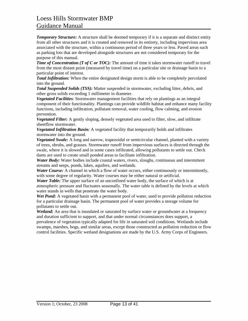
BMP Reference 2E-2 Infiltration Trenches or Dry Well Seepage Pits
Source: EPA Stormwater Fact Sheet – Infiltration Trench
The following items are recommendations in addition to the ISWMM design guidelines:
• Geotechnical o Perform percolation tests, soils analysis to determine allowable shear stress, soil
profiles, groundwater elevation, collapsible soils, and bedrock. o Upland slopes.
• Hydrology o Be mindful of stormwater source to infiltration trench o Size basins so that the water quality volume is infiltrated within 48-72 hours
• BMP Placement o Place downstream of collection and treatment facilities o Avoid placement near structures with basements o Avoid high sediment loading potential with upstream practices. o Phase construction of this BMP after upstream stormwater quality treatment
devices are in place to avoid fouling the trench or pit. o Ideally suited for roof runoff. o Avoid placement on fill soils – soil compaction reduces infiltration capacity. o Avoid placement on slopes greater than 12 percent. o Avoid placement near septic systems, adsorption fields or other on-site
wastewater facilities. o Avoid placement where potential is high for anthropogenic (man-made) spills.
Design Criteria for use in loess soils • Determine Existing and High Groundwater Elevations. • Identify Bedrock Elevation • Specify geotextile based on in-situ soil characteristics • Portion of trench or pit should be below frost line so that the practice will function in cold
weather.
Maintenance Requirements for use in loess soils • Maintenance items identified in ISWMM • Inspect and maintain stormwater treatment devices upstream of infiltration trenches
BMP Suitability for Loess Soils Residential Yes Commercial Yes Industrial Yes Retrofit Yes
Please refer to Iowa Stormwater Management Manual – Best Management Practice 2E-2 Infiltration Trench for specifics on use and design of this BMP.

Loess Hills Stormwater BMP 2E-3 Guidance Manual
Version 1; October, 23 2008 Page 18 of 41
BMP Reference 2E-3 Infiltration Basin
Photo: Bob Elbert Iowa State University
The following items are recommendations in addition to the ISWMM design guidelines: Required Site Investigations • Geotechnical
o Perform percolation tests, soils analysis to determine allowable shear stress, soil profiles, groundwater elevation, collapsible soils, and bedrock.
o Verify existing slopes. • Hydrology
o Be mindful of stormwater source to infiltration basin o Size basins so that the water quality volume is infiltrated within 48-72 hours
• BMP Placement o Place downstream of collection facilities. o Avoid placement near structures with basements. o Avoid placement on fill soils o Avoid placement on slopes greater than 20 percent.
Design Criteria for use in loess soils • Determine Existing and High Groundwater Elevations. • Identify Bedrock Elevation • Perform shear stress evaluation at outlet for energy dissipator design • Establish vegetation as soon as feasible on basin floor and slopes.
Maintenance Requirements for use in loess soils • Maintenance items identified in ISWMM • Inspect and maintain stormwater treatment devices upstream of infiltration trenches • Avoid excessive compaction and sediment loading during construction
BMP Suitability for Loess Soils Residential Yes Commercial Yes Industrial Yes Retrofit Yes
Please refer to Iowa Stormwater Management Manual – Best Management Practice 2E-3 Infiltration Basin for specifics on use and design of this BMP.

Loess Hills Stormwater BMP 2E-4 Guidance Manual
Version 1; October, 23 2008 Page 19 of 41
BMP Reference 2E-4 Bioretention Systems
The following items are recommendations in addition to the ISWMM design guidelines:
Required Site Investigations • Geotechnical
o Perform percolation tests, soils analysis, soil profiles, groundwater elevation, collapsible soils, and bedrock.
o Verify existing slopes. • Hydrology
o Be mindful of stormwater source to bioretention basin. High sediment loading will cause failure of the system.
o Size basins so that the water quality volume is infiltrated within 4-12 hours. • BMP Placement
o Place downstream of collection facilities. o Ideally suited for pavement runoff or roof runoff. o Avoid high sediment loading potential with upstream practice of filter strip or
grassed swale. o Avoid concentrated inflows. o Avoid placement on fill soils o Avoid placement on slopes greater than 15 percent.
Design Criteria for use in loess soils • Determine Existing and Seasonal High Groundwater Elevations. • Identify Bedrock Elevation. • Design inlet to bioretention overflow system to prevent scouring. • Design of bioretention overflow spillway to prevent scouring of spillway. • Establish vegetation as soon as feasible on basin floor and slopes. • Careful selection of native plants required. • Modify soil composition to support native plants and retain moisture for use by native
plants.
Maintenance Requirements for use in loess soils • Routine Maintenance items identified in Iowa Stormwater Management Manual • Inspect and maintain stormwater treatment devices upstream of bioretention systems. • Avoid excessive compaction and sediment loading during construction.
BMP Suitability for Loess Soils Residential Yes Commercial Yes Industrial Yes Retrofit Yes
Please refer to Iowa Stormwater Management Manual – Best Management Practice 2E-4 Bioretention Systems for specifics on use and design of this BMP.
Loess Hills Stormwater BMP 2E-X Guidance Manual
Version 1; October, 23 2008 Page 20 of 41
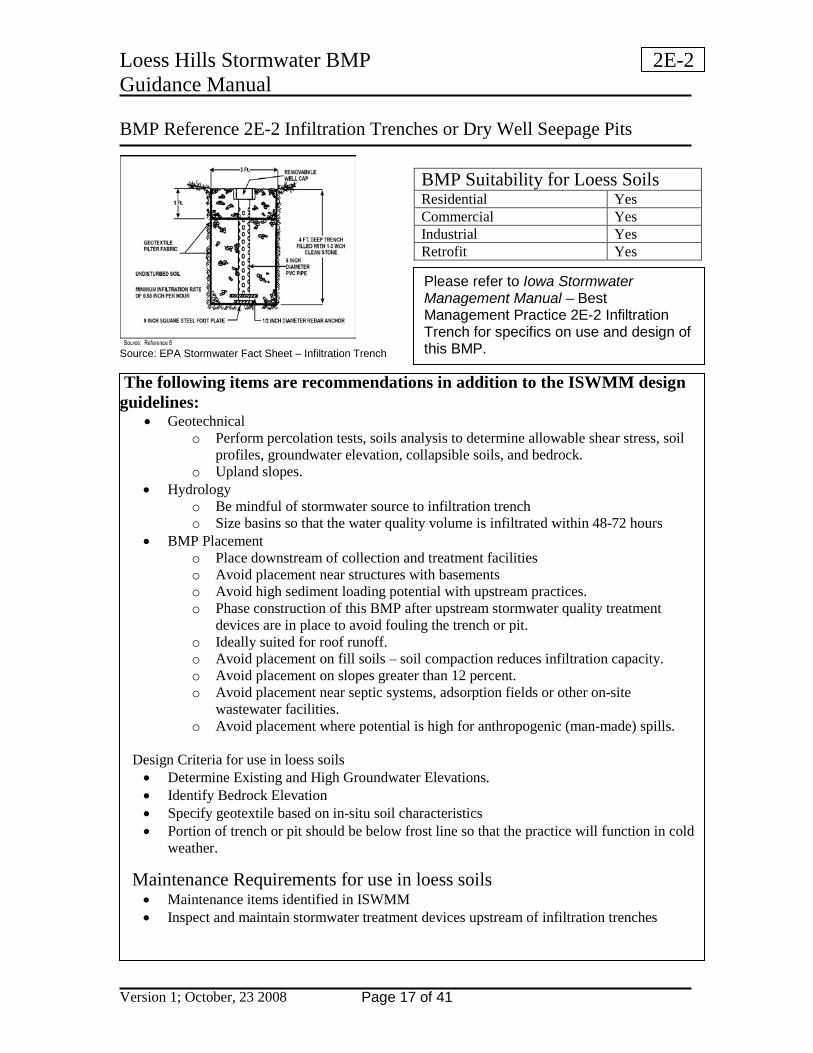
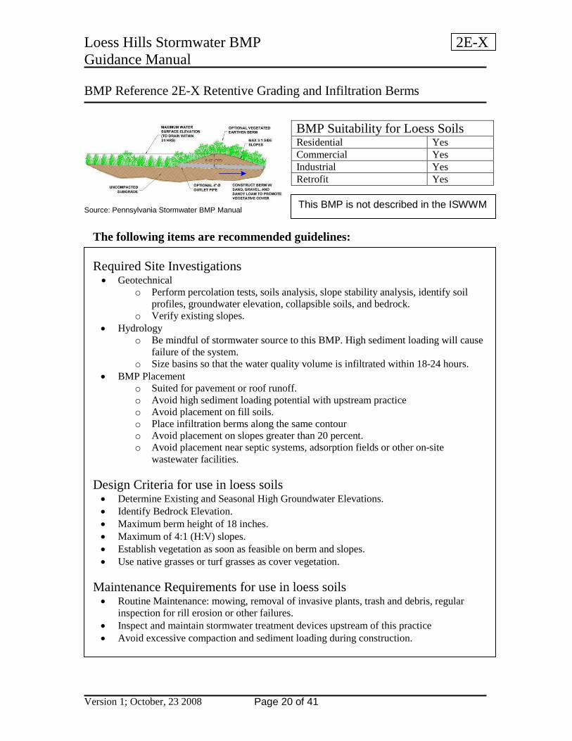
BMP Reference 2E-X Retentive Grading and Infiltration Berms Source: Pennsylvania Stormwater BMP Manual
The following items are recommended guidelines: Required Site Investigations • Geotechnical
o Perform percolation tests, soils analysis, slope stability analysis, identify soil profiles, groundwater elevation, collapsible soils, and bedrock.
o Verify existing slopes. • Hydrology
o Be mindful of stormwater source to this BMP. High sediment loading will cause failure of the system.
o Size basins so that the water quality volume is infiltrated within 18-24 hours. • BMP Placement
o Suited for pavement or roof runoff. o Avoid high sediment loading potential with upstream practice o Avoid placement on fill soils. o Place infiltration berms along the same contour o Avoid placement on slopes greater than 20 percent. o Avoid placement near septic systems, adsorption fields or other on-site
wastewater facilities. Design Criteria for use in loess soils • Determine Existing and Seasonal High Groundwater Elevations. • Identify Bedrock Elevation. • Maximum berm height of 18 inches. • Maximum of 4:1 (H:V) slopes. • Establish vegetation as soon as feasible on berm and slopes. • Use native grasses or turf grasses as cover vegetation.
Maintenance Requirements for use in loess soils • Routine Maintenance: mowing, removal of invasive plants, trash and debris, regular
inspection for rill erosion or other failures. • Inspect and maintain stormwater treatment devices upstream of this practice • Avoid excessive compaction and sediment loading during construction.
BMP Suitability for Loess Soils Residential Yes Commercial Yes Industrial Yes Retrofit Yes
This BMP is not described in the ISWWM
Loess Hills Stormwater BMP 2E-7 Guidance Manual
Version 1; October, 23 2008 Page 21 of 41
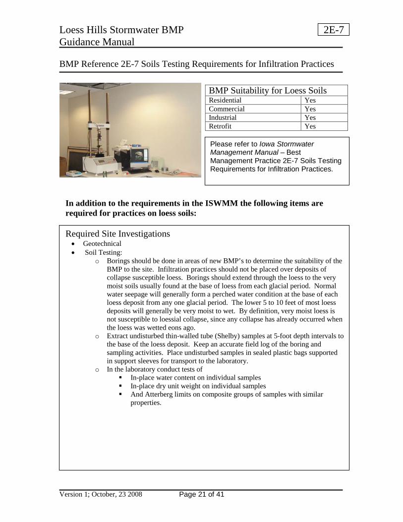
BMP Reference 2E-7 Soils Testing Requirements for Infiltration Practices
In addition to the requirements in the ISWMM the following items are required for practices on loess soils: Required Site Investigations • Geotechnical • Soil Testing:
o Borings should be done in areas of new BMP’s to determine the suitability of the BMP to the site. Infiltration practices should not be placed over deposits of collapse susceptible loess. Borings should extend through the loess to the very moist soils usually found at the base of loess from each glacial period. Normal water seepage will generally form a perched water condition at the base of each loess deposit from any one glacial period. The lower 5 to 10 feet of most loess deposits will generally be very moist to wet. By definition, very moist loess is not susceptible to loessial collapse, since any collapse has already occurred when the loess was wetted eons ago.
o Extract undisturbed thin-walled tube (Shelby) samples at 5-foot depth intervals to the base of the loess deposit. Keep an accurate field log of the boring and sampling activities. Place undisturbed samples in sealed plastic bags supported in support sleeves for transport to the laboratory.
o In the laboratory conduct tests of In-place water content on individual samples In-place dry unit weight on individual samples And Atterberg limits on composite groups of samples with similar
properties.
BMP Suitability for Loess Soils Residential Yes Commercial Yes Industrial Yes Retrofit Yes
Please refer to Iowa Stormwater Management Manual – Best Management Practice 2E-7 Soils Testing Requirements for Infiltration Practices.
Loess Hills Stormwater BMP 2E-7 Guidance Manual
Version 1; October, 23 2008 Page 22 of 41
Required Site Investigations continued
• Analyses: o Compare the in-place water content to the Atterberg limits to determine the in-
place soil phase; solid, plastic, or liquid. o Compare the in-place water content and dry unit weight to the 10% water content
and 80 pcf dry unit weight. Use these comparisons to determine potential for loessial collapse. If loessial collapse potential is high, water content less than 10% and dry unit weight less than 80 pcf, do not allow infiltration beds. If loessial collapse is moderate potential, dry unit weight of less than 80 pcf and water content between 10 and 16%, then look at soil in-place phase as determined by comparison of in-place water content to Atterberg limits. If the soil exists in the solid phase, do not allow infiltration beds. If the soil already exists in the plastic phase, allow infiltration beds. If the soil exists in the liquid phase, it is generally already too wet to allow additional infiltration. Percolation rate will further determine the ability of a soil that has a low potential for loessial collapse to accept infiltration water. Near steep slopes and other slopes with a history of failures, conduct additional test of:
• soil strength, shear strength and angle of internal friction with triaxial tests. Determine stability of slope as it exists. Determine stability of slope with new fill or with infiltration-related affects on the soil. Soil does not need to collapse in order for increased water content to affect it. The added effective weigh of the soil due to water content increase may initiate a failure with no change in soil strength occurring.
Loess Hills Stormwater BMP 2E-7 Guidance Manual
Version 1; October, 23 2008 Page 23 of 41
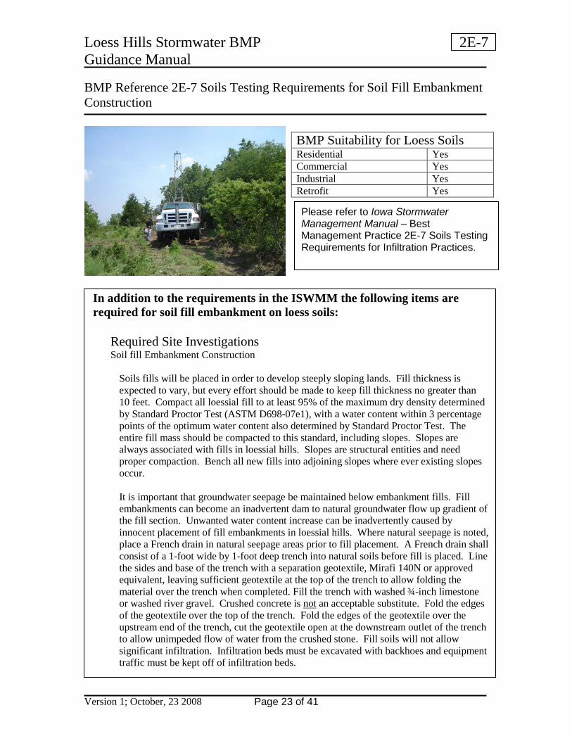
BMP Reference 2E-7 Soils Testing Requirements for Soil Fill Embankment Construction
In addition to the requirements in the ISWMM the following items are required for soil fill embankment on loess soils:
Required Site Investigations Soil fill Embankment Construction
Soils fills will be placed in order to develop steeply sloping lands. Fill thickness is expected to vary, but every effort should be made to keep fill thickness no greater than 10 feet. Compact all loessial fill to at least 95% of the maximum dry density determined by Standard Proctor Test (ASTM D698-07e1), with a water content within 3 percentage points of the optimum water content also determined by Standard Proctor Test. The entire fill mass should be compacted to this standard, including slopes. Slopes are always associated with fills in loessial hills. Slopes are structural entities and need proper compaction. Bench all new fills into adjoining slopes where ever existing slopes occur. It is important that groundwater seepage be maintained below embankment fills. Fill embankments can become an inadvertent dam to natural groundwater flow up gradient of the fill section. Unwanted water content increase can be inadvertently caused by innocent placement of fill embankments in loessial hills. Where natural seepage is noted, place a French drain in natural seepage areas prior to fill placement. A French drain shall consist of a 1-foot wide by 1-foot deep trench into natural soils before fill is placed. Line the sides and base of the trench with a separation geotextile, Mirafi 140N or approved equivalent, leaving sufficient geotextile at the top of the trench to allow folding the material over the trench when completed. Fill the trench with washed ¾-inch limestone or washed river gravel. Crushed concrete is not an acceptable substitute. Fold the edges of the geotextile over the top of the trench. Fold the edges of the geotextile over the upstream end of the trench, cut the geotextile open at the downstream outlet of the trench to allow unimpeded flow of water from the crushed stone. Fill soils will not allow significant infiltration. Infiltration beds must be excavated with backhoes and equipment traffic must be kept off of infiltration beds.
BMP Suitability for Loess Soils Residential Yes Commercial Yes Industrial Yes Retrofit Yes
Please refer to Iowa Stormwater Management Manual – Best Management Practice 2E-7 Soils Testing Requirements for Infiltration Practices.

Loess Hills Stormwater BMP 2F-2 Guidance Manual
Version 1; October, 23 2008 Page 24 of 41
BMP Reference 2F-2 Surface and Perimeter Sand Filters Flow-through Sand Filter Detail. Source: City of Portland 2004 Stormwater Management Manual.
The following items are recommendations in addition to the ISWMM design guidelines:
Required Site Investigations for Earthen Structures • Geotechnical
o Perform percolation tests and soils analysis to determine, infiltration rate, allowable shear stress, soil profiles, groundwater elevation, and depth to bedrock.
• Hydrology o Evaluate erosion potential of by-passed flows. o Use poly-liner or impermeable membrane to seal bottom of earthen structure.
Design Criteria • Perform shear stress evaluation at outlet for energy dissipator design if not discharging
into a conduit conveyance system. Operation and Maintenance Activities • Test for water tightness of membrane prior to placing filter media. • Monitor vegetation establishment in the overflow facilities.
BMP Suitability for Loess Soils Residential Yes Commercial Yes Industrial Yes Retrofit Yes
Please refer to Iowa Stormwater Management Manual – Best Management Practice 2F-2 Surface and Perimeter Sand Drain Filters for specifics on use and design of this BMP.

Loess Hills Stormwater BMP 2F-3 Guidance Manual
Version 1; October, 23 2008 Page 25 of 41
BMP Reference 2F-3 Underground Sand Filter Source Ben Urbonas at UDFCD
The following items are recommendations in addition to the ISWMM design guidelines:
Required Site Investigations for Earthen Structures • Geotechnical
o Perform soils analysis to determine, soil profiles, groundwater elevation, and depth to bedrock.
• Hydrology o Evaluate erosion potential of by-passed flows.
Design Criteria • Perform shear stress evaluation at outlet for energy dissipator design if not discharging
into a conduit conveyance system. Operation and Maintenance Activities • Not recommended for residential developments due to high maintenance costs. • Test for water tightness of structure prior to placing filter media. • Monitor vegetation establishment in the overflow facilities.
BMP Suitability for Loess Soils Residential No Commercial Yes Industrial Yes Retrofit Yes
Please refer to Iowa Stormwater Management Manual – Best Management Practice 2F-3 Underground Sand Filters for specifics on use and design of this BMP.
Loess Hills Stormwater BMP 2G-2 Guidance Manual
Version 1; October, 23 2008 Page 26 of 41
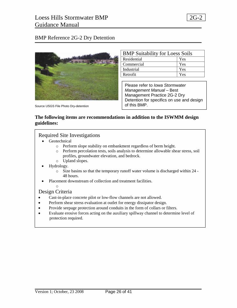
BMP Reference 2G-2 Dry Detention Source USGS File Photo Dry-detention The following items are recommendations in addition to the ISWMM design guidelines:
Required Site Investigations • Geotechnical
o Perform slope stability on embankment regardless of berm height. o Perform percolation tests, soils analysis to determine allowable shear stress, soil
profiles, groundwater elevation, and bedrock. o Upland slopes.
• Hydrology. o Size basins so that the temporary runoff water volume is discharged within 24 -
48 hours. • Placement downstream of collection and treatment facilities.
o Design Criteria • Cast-in-place concrete pilot or low-flow channels are not allowed. • Perform shear stress evaluation at outlet for energy dissipator design. • Provide seepage protection around conduits in the form of collars or filters. • Evaluate erosive forces acting on the auxiliary spillway channel to determine level of
protection required.
BMP Suitability for Loess Soils Residential Yes Commercial Yes Industrial Yes Retrofit Yes
Please refer to Iowa Stormwater Management Manual – Best Management Practice 2G-2 Dry Detention for specifics on use and design of this BMP.
Loess Hills Stormwater BMP 2G-3 Guidance Manual
Version 1; October, 23 2008 Page 27 of 41
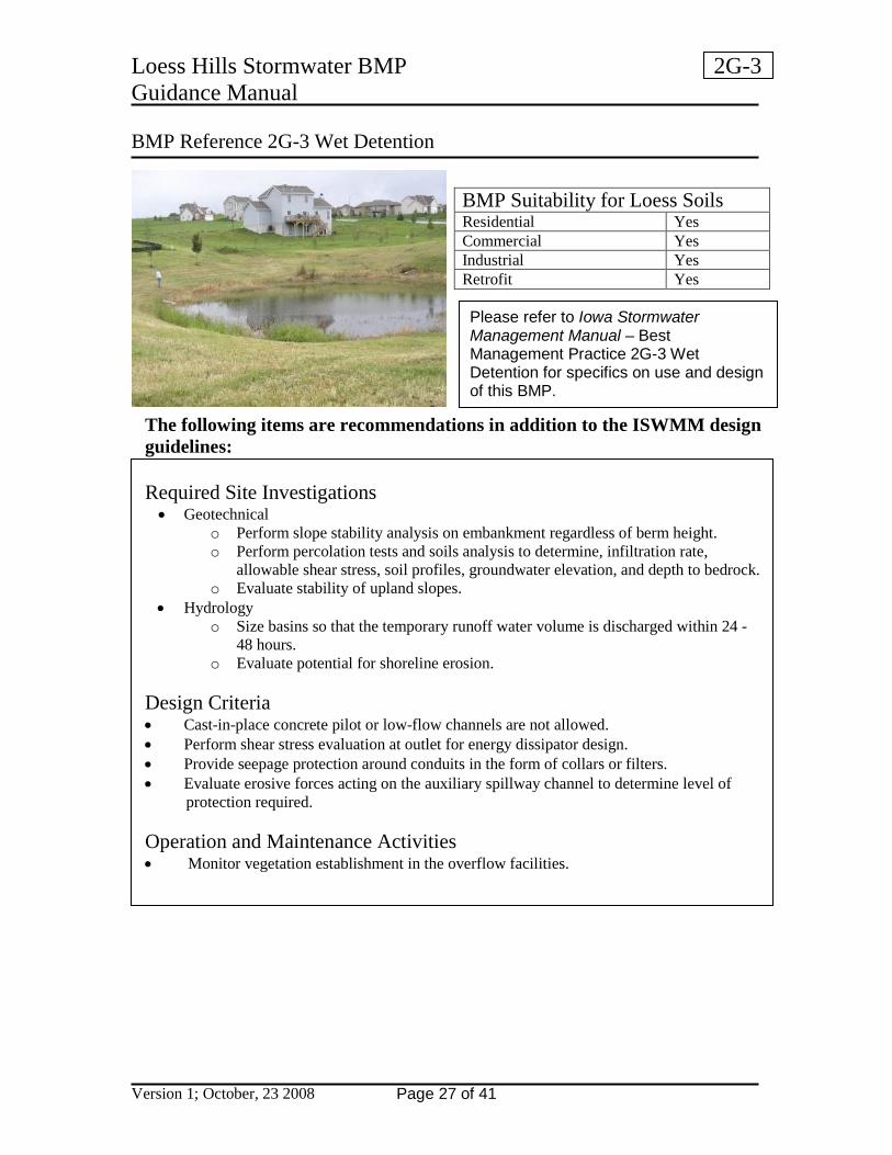
BMP Reference 2G-3 Wet Detention
The following items are recommendations in addition to the ISWMM design guidelines:
Required Site Investigations • Geotechnical
o Perform slope stability analysis on embankment regardless of berm height. o Perform percolation tests and soils analysis to determine, infiltration rate,
allowable shear stress, soil profiles, groundwater elevation, and depth to bedrock. o Evaluate stability of upland slopes.
• Hydrology o Size basins so that the temporary runoff water volume is discharged within 24 -
48 hours. o Evaluate potential for shoreline erosion.
Design Criteria • Cast-in-place concrete pilot or low-flow channels are not allowed. • Perform shear stress evaluation at outlet for energy dissipator design. • Provide seepage protection around conduits in the form of collars or filters. • Evaluate erosive forces acting on the auxiliary spillway channel to determine level of
protection required. Operation and Maintenance Activities • Monitor vegetation establishment in the overflow facilities.
BMP Suitability for Loess Soils Residential Yes Commercial Yes Industrial Yes Retrofit Yes
Please refer to Iowa Stormwater Management Manual – Best Management Practice 2G-3 Wet Detention for specifics on use and design of this BMP.
Loess Hills Stormwater BMP 2H-2 Guidance Manual
Version 1; October, 23 2008 Page 28 of 41
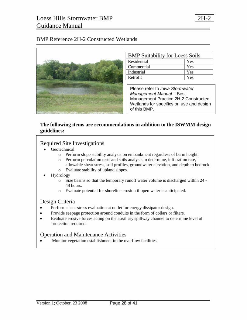
BMP Reference 2H-2 Constructed Wetlands
The following items are recommendations in addition to the ISWMM design guidelines:
Required Site Investigations • Geotechnical
o Perform slope stability analysis on embankment regardless of berm height. o Perform percolation tests and soils analysis to determine, infiltration rate,
allowable shear stress, soil profiles, groundwater elevation, and depth to bedrock. o Evaluate stability of upland slopes.
• Hydrology o Size basins so that the temporary runoff water volume is discharged within 24 -
48 hours. o Evaluate potential for shoreline erosion if open water is anticipated.
Design Criteria • Perform shear stress evaluation at outlet for energy dissipator design. • Provide seepage protection around conduits in the form of collars or filters. • Evaluate erosive forces acting on the auxiliary spillway channel to determine level of
protection required. Operation and Maintenance Activities • Monitor vegetation establishment in the overflow facilities
BMP Suitability for Loess Soils Residential Yes Commercial Yes Industrial Yes Retrofit Yes
Please refer to Iowa Stormwater Management Manual – Best Management Practice 2H-2 Constructed Wetlands for specifics on use and design of this BMP.

Loess Hills Stormwater BMP 2I-2 Guidance Manual
Version 1; October, 23 2008 Page 29 of 41
BMP Reference 2I-2 Grassed Swales
The following items are recommendations in addition to the ISWMM design guidelines:
Required Site Investigations • Geotechnical
o Perform soils analysis to determine, soil profiles, groundwater elevation, and depth to bedrock.
• Hydrology o Evaluate erosion potential. o Consider temporary by-pass during establishment of vegetation.
Design Criteria • Perform shear stress evaluation limit velocities to non erosive values. • Protect swale on downstream edge of check dams from erosion. • Maximum velocity for Qwq = 1.0 fps. • Maximum velocity for 2-year and 10-year storms based on allowable shear stress. Operation and Maintenance Activities • Observe the facility monthly to monitor erosion and vegetation establishment during first
year of operation.
BMP Suitability for Loess Soils Residential Yes Commercial Yes Industrial Yes Retrofit Yes
Please refer to Iowa Stormwater Management Manual – Best Management Practice 2I-2 Grassed Swales for specifics on use and design of this BMP.

Loess Hills Stormwater BMP 2I-3 Guidance Manual
Version 1; October, 23 2008 Page 30 of 41
BMP Reference 2I-3 Dry and Wet Swales
The following items are recommendations in addition to the ISWMM design guidelines:
Required Site Investigations • Geotechnical
o Perform soils analysis to determine, soil profiles, groundwater elevation, and depth to bedrock.
o Wet swales evaluate potential for bank erosion. • Hydrology
o Evaluate erosion potential. o Consider temporary by-pass during establishment of vegetation.
Design Criteria • Perform shear stress evaluation limit velocities to non-erosive values to reduce
resuspension of accumulated materials. • Protect swale on downstream edge of check dams from erosion. • Maximum velocity for Qwq = 1.0 fps. • Maximum velocity for 2-year and 10-year storms based on allowable shear stress. Operation and Maintenance Activities • Observe the facility monthly to monitor erosion and vegetation establishment during first
year of operation.
BMP Suitability for Loess Soils Residential Yes Commercial Yes Industrial Yes Retrofit Yes
Please refer to Iowa Stormwater Management Manual – Best Management Practice 2I-3 Dry and Wet Swales for specifics on use and design of this BMP.

Loess Hills Stormwater BMP 2I-4 Guidance Manual
Version 1; October, 23 2008 Page 31 of 41
BMP Reference 2I-4 Grassed Vegetated Filter Strips From City of Portland 2004 Stormwater Management Manual
The following items are recommendations in addition to the ISWMM design guidelines:
Required Site Investigations • Geotechnical
o Perform soils analysis to determine, soil profiles, groundwater elevation, and depth to bedrock.
• Hydrology o Evaluate erosion potential. o Consider temporary by-pass during establishment of vegetation.
Design Criteria • Perform shear stress evaluation limit velocities to non erosive values. • Operation and Maintenance Activities • Observe the facility monthly to monitor erosion and vegetation establishment during first
year of operation.
BMP Suitability for Loess Soils Residential Yes Commercial Yes Industrial Yes Retrofit Yes
Please refer to Iowa Stormwater Management Manual – Best Management Practice 2I-4 Grassed Vegetated Filter Strips for specifics on use and design of this BMP.

Loess Hills Stormwater BMP 2J-4 Guidance Manual
Version 1; October, 23 2008 Page 32 of 41
BMP Reference 2J-4 Pervious Pavement
The following items are recommendations in addition to the ISWMM design guidelines:
Required Site Investigations • Geotechnical
o Perform percolation tests, soils analysis, bearing capacities, slope stability analysis, identify soil profiles, groundwater elevation, collapsible soils, and bedrock.
o Verify existing slopes. • Hydrology
o Be mindful of stormwater source to this BMP. High sediment loading will cause failure of the system.
o Size basins so that the water quality volume is infiltrated within 18-24 hours. • BMP Placement
o Avoid high sediment loading potential. o Restrict to sidewalks, parking magazines, alleys, drives and private roads. o Avoid areas with a high potential for anthropogenic (man-made) spills. o Use with Subsurface Infiltration beds, bioretention systems or vegetated swales
as secondary treatment and conveyance methods. o Slopes should be less than 5 to 10 percent
Design Criteria for use in loess soils • Pavement must allow runoff to infiltrate into a permeable media below the pavement
section. • Provide distributed infiltration area (5:1 ratio of impervious area to infiltration area -
maximum), • Underdrain system will be required where existing soil conditions are not suited to
infiltration or soils are classified as collapsible.
BMP Suitability for Loess Soils Residential Yes Commercial Yes Industrial Yes Retrofit Yes
This BMP is under development in the ISWWM.
Loess Hills Stormwater BMP 2J-4 Guidance Manual
Version 1; October, 23 2008 Page 33 of 41
BMP Reference 2J-4 Pervious Pavement (continued)
• Infiltration Bed shall be wrapped in nonwoven geotextile. • Level or nearly level bed bottoms • Protect from sedimentation during construction • Provide perforated pipe network along bed bottom for distribution and conveyance as
necessary Maintenance Requirements for use in loess soils • Inspect catch basins and inlets every three months following installation and after
significant runoff events (>10-year) for the first two years. Semi-annual inspections after two years. Remove accumulated sediment, trash or debris as necessary.
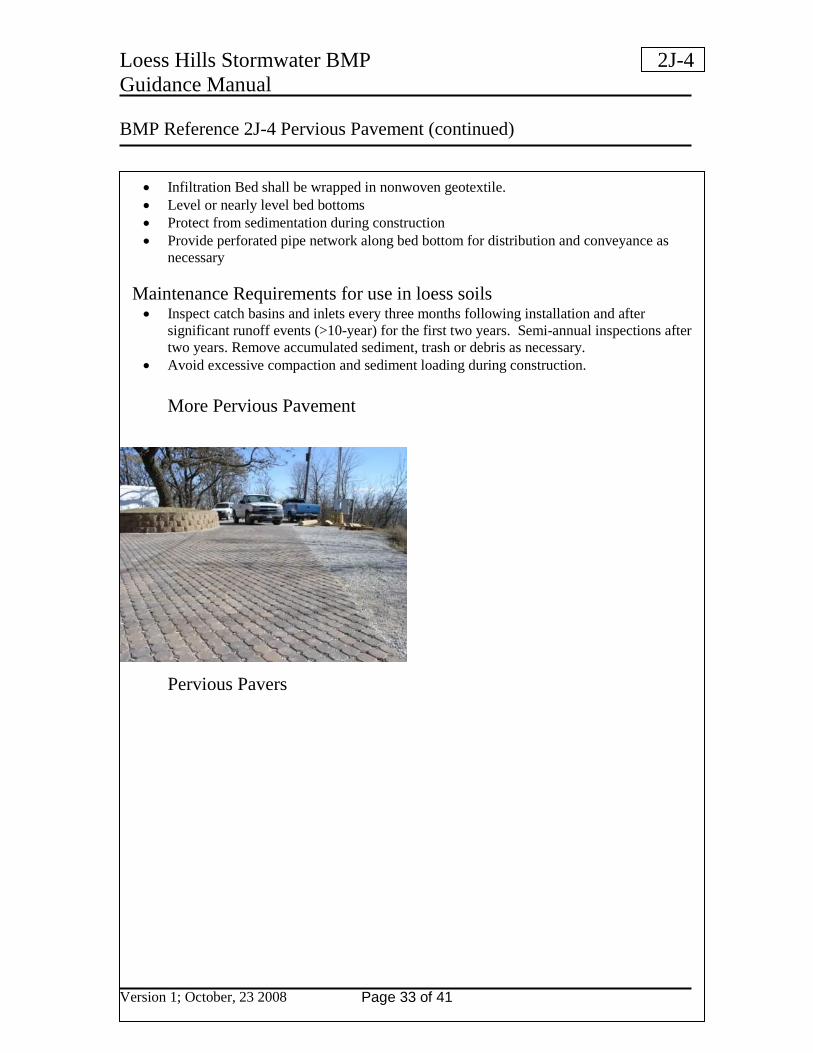
• Avoid excessive compaction and sediment loading during construction. More Pervious Pavement
Pervious Pavers
Loess Hills Stormwater BMP 2K-1 Guidance Manual
Version 1; October, 23 2008 Page 34 of 41
BMP Reference 2K-1Mechanical System No Photo
This BMP is under development and is not included in the ISWWM so no additional guidance is provided at this time.
BMP Suitability for Loess Soils Residential Yes Commercial Yes Industrial Yes Retrofit Yes
This BMP is under development in the ISWWM.
Loess Hills Stormwater BMP 2L-1 Guidance Manual
Version 1; October, 23 2008 Page 35 of 41
BMP Reference 2L-1Chemical Treatment for Turbidity Removal No Photo
This BMP is under development and is not included in the ISWWM so no additional guidance is provided at this time.
BMP Suitability for Loess Soils Residential Yes Commercial Yes Industrial Yes Retrofit Yes
This BMP is under development in the ISWWM.

Loess Hills Stormwater BMP 2M-1 Guidance Manual
Version 1; October, 23 2008 Page 36 of 41
BMP Reference 2M-1 General Information for Storm Sewer Design
The following items are recommendations in addition to the ISWMM design guidelines:
Required Site Investigations Numerous pipe failures have been linked to leaking pipe joints in loess and other geologic settings. • Geotechnical
o Perform slope stability analysis on embankment regardless of berm height. o Perform percolation tests and soils analysis to determine, infiltration rate,
allowable shear stress, soil profiles, groundwater elevation, and depth to bedrock. • Hydrology
o Evaluate potential for entrance and exit erosion.
Design Criteria • Require sealed joints on storm drain conduits. • Require restrained joints on steep slopes or other areas where water hammer or pressure
could displace the pipe. • Perform shear stress evaluation at outlet for energy dissipator design. • Provide seepage protection around conduits in the form of collars or filters for structures
with a permanent upstream water surface. • Refer to the addendum to Table 3 Section 2O-2 Open Channel Flow for permissible open
channel velocities when sizing energy dissipators, shown below.
BMP Suitability for Loess Soils Residential Yes Commercial Yes Industrial Yes Retrofit Yes
Please refer to Iowa Stormwater Management Manual – Best Management Practice 2M-1 General Information for Storm Sewer Design for specifics on use and design of this BMP.
Loess Hills Stormwater BMP 2M-1 Guidance Manual
Version 1; October, 23 2008 Page 37 of 41
BMP Reference 2M-1 General Information for Storm Sewer Design (continued)
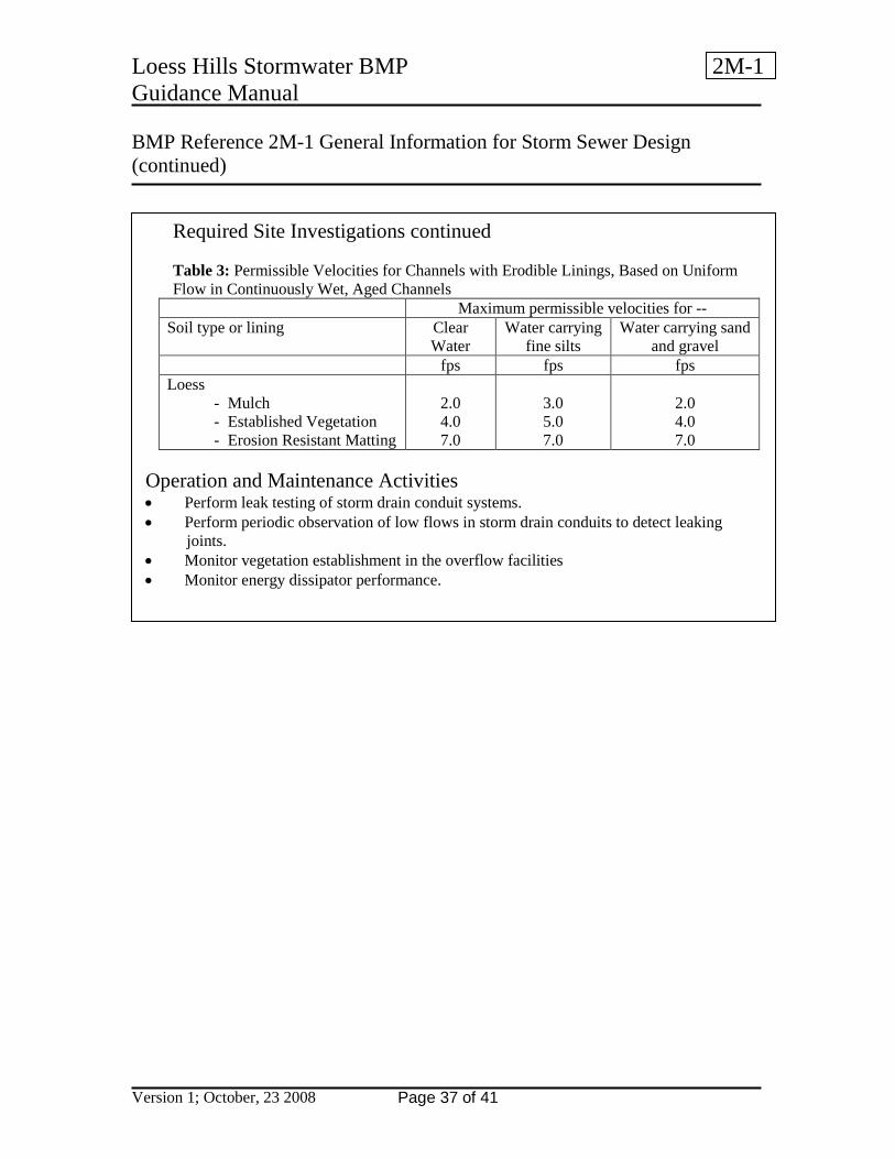
Required Site Investigations continued Table 3: Permissible Velocities for Channels with Erodible Linings, Based on Uniform Flow in Continuously Wet, Aged Channels
Maximum permissible velocities for -- Soil type or lining
Clear Water
Water carrying fine silts
Water carrying sand and gravel
fps fps fps Loess
- Mulch - Established Vegetation - Erosion Resistant Matting
2.0 4.0 7.0
3.0 5.0 7.0
2.0 4.0 7.0
Operation and Maintenance Activities • Perform leak testing of storm drain conduit systems. • Perform periodic observation of low flows in storm drain conduits to detect leaking
joints. • Monitor vegetation establishment in the overflow facilities • Monitor energy dissipator performance.
Loess Hills Stormwater BMP 2N-1 Guidance Manual
Version 1; October, 23 2008 Page 38 of 41
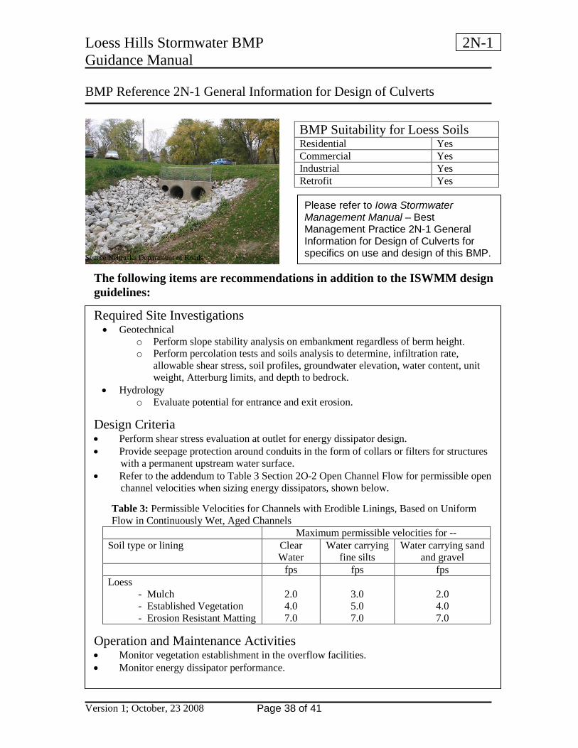
BMP Reference 2N-1 General Information for Design of Culverts Source Nebraska Department of Roads
The following items are recommendations in addition to the ISWMM design guidelines:
Required Site Investigations • Geotechnical
o Perform slope stability analysis on embankment regardless of berm height. o Perform percolation tests and soils analysis to determine, infiltration rate,
allowable shear stress, soil profiles, groundwater elevation, water content, unit weight, Atterburg limits, and depth to bedrock.
• Hydrology o Evaluate potential for entrance and exit erosion.
Design Criteria • Perform shear stress evaluation at outlet for energy dissipator design. • Provide seepage protection around conduits in the form of collars or filters for structures
with a permanent upstream water surface. • Refer to the addendum to Table 3 Section 2O-2 Open Channel Flow for permissible open
channel velocities when sizing energy dissipators, shown below. Table 3: Permissible Velocities for Channels with Erodible Linings, Based on Uniform Flow in Continuously Wet, Aged Channels
Maximum permissible velocities for -- Soil type or lining
Clear Water
Water carrying fine silts
Water carrying sand and gravel
fps fps fps Loess
- Mulch - Established Vegetation - Erosion Resistant Matting
2.0 4.0 7.0
3.0 5.0 7.0
2.0 4.0 7.0
Operation and Maintenance Activities • Monitor vegetation establishment in the overflow facilities. • Monitor energy dissipator performance.
BMP Suitability for Loess Soils Residential Yes Commercial Yes Industrial Yes Retrofit Yes
Please refer to Iowa Stormwater Management Manual – Best Management Practice 2N-1 General Information for Design of Culverts for specifics on use and design of this BMP.
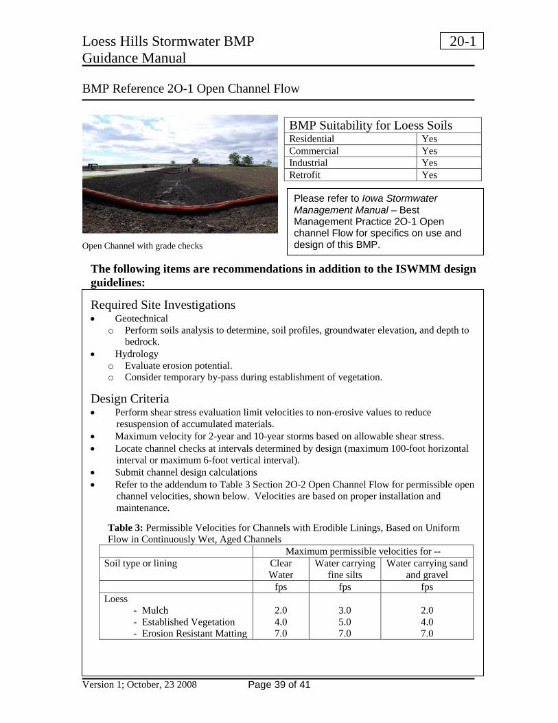
Loess Hills Stormwater BMP 20-1 Guidance Manual
Version 1; October, 23 2008 Page 39 of 41
BMP Reference 2O-1 Open Channel Flow Open Channel with grade checks
The following items are recommendations in addition to the ISWMM design guidelines:
Required Site Investigations • Geotechnical
o Perform soils analysis to determine, soil profiles, groundwater elevation, and depth to bedrock.
• Hydrology o Evaluate erosion potential. o Consider temporary by-pass during establishment of vegetation.
Design Criteria • Perform shear stress evaluation limit velocities to non-erosive values to reduce
resuspension of accumulated materials. • Maximum velocity for 2-year and 10-year storms based on allowable shear stress. • Locate channel checks at intervals determined by design (maximum 100-foot horizontal
interval or maximum 6-foot vertical interval). • Submit channel design calculations • Refer to the addendum to Table 3 Section 2O-2 Open Channel Flow for permissible open
channel velocities, shown below. Velocities are based on proper installation and maintenance.
Table 3: Permissible Velocities for Channels with Erodible Linings, Based on Uniform Flow in Continuously Wet, Aged Channels
Maximum permissible velocities for -- Soil type or lining
Clear Water
Water carrying fine silts
Water carrying sand and gravel
fps fps fps Loess
- Mulch - Established Vegetation - Erosion Resistant Matting
2.0 4.0 7.0
3.0 5.0 7.0
2.0 4.0 7.0
BMP Suitability for Loess Soils Residential Yes Commercial Yes Industrial Yes Retrofit Yes
Please refer to Iowa Stormwater Management Manual – Best Management Practice 2O-1 Open channel Flow for specifics on use and design of this BMP.

Loess Hills Stormwater BMP 20-1 Guidance Manual
Version 1; October, 23 2008 Page 40 of 41
BMP Reference 2O-1 Open Channel Flow (continued)
Operation and Maintenance Activities • Observe the facility monthly to monitor erosion and vegetation establishment during first
year of operation. • If mown, leave clippings on the ground.
Loess Hills Stormwater BMP Guidance Manual
Version 1; October, 23 2008 Page 41 of 41
References Statewide Urban Design and Specifications (SUDAS) Design Manual, 2008, Iowa SUDAS Corporation. Iowa Storm Water Management Manual (ISWMM), February 2007, Center for Transportation Research and Education. Storm Water Technology Fact Sheet - Infiltration Trench, EPA 832-F-99-019 September 1999, www.epa.gov-npdes-pubs-infltrenc.pdf, US Environmental Protection Agency. Portland Stormwater Management Manual Adopted July 1, 10999; revised September 1, 2004, City of Portland, Oregon. Pennsylvania Stormwater Best Management Practices Manual, December 30, 2006, Pennsylvania Department of Environmental Protection, Bureau of Watershed Management. Hydraulic Design of Sand Filters for Stormwater Quality by Ben R. Urbonas, Chief, Master Planning Program, Denver, Colorado, Urban Drainage and Flood Control District
Photography Credits All photographs unless otherwise noted provided by Rich Maaske or Danelle Schmielau West Pottawattamie County (Iowa) Soil and Water Conservation District.