Locking Assemblies Shrink Discs Rigid Couplings
20
www.mav.it M I N I Locking Assemblies Shrink Discs Rigid Couplings
Transcript of Locking Assemblies Shrink Discs Rigid Couplings

www.mav. i t
M I N I
Locking Assemblies Shrink Discs Rigid Couplings

M I N I2
We are an Italian company world renowned for our creativity and
ethics. Established in 1989 we have rapidly built a reputation for
professional, reliable and comprehensive service and our extensive
product range. We are located in Bosentino in Northern Italy, at the
foot of the Dolomites, one of the most beautiful areas of the Alps.
Just as our products connect mechanical components in motion
technology our purpose is to unite our partners with their goals,
feelings, wishes - emotions. We aim to raise the standards in our
industry in conjuntion with customers and suppliers who share our
goals of quality, safety and environmental conservation.
We see the market as a huge mosaic of which manufacturers,
suppliers and customers are all part. Together we form a global
partnership sharing common goals for our mutual benefi t. In this
mosaic we have a central position and wish to be a key point of
reference.
Sandro Zamboni (MAV President)
our mission
our company
our vision

M I N I 3
Index
Shaft-Hub Connections: Traditional Methods
Shaft-Hub Connections: The MAV System
MAV 2061
MAV 5061
MAV 7903
MAV 1204
MAV 3008
Installation Instruction for Mini Locking Assemblies
Installation Instruction for Mini Rigid Couplings
Installation Instruction for Mini Shrink Discs
Technical Support
4
56-7
8-910-11
This catalogue contains complete information for the new MAV Mini Series line of Keyless Shaft-Hub Locking Devices.
The following pages will help you to fi nd the perfect solution for your application. Should you require assistance with an application,
please feel free to contact MAV technical support. Our engineers will be pleased to provide any information you might need.
© 2005 MAV S.p.A. All rights reserved.
This catalogue may not be reproduced, either wholly or partly without the written authorisation of MAV S.p.A.
Information subject to change without prior notifi cation.
12-13
14-15
1617
1819

M I N I4
Keyway and splined locking systems show important disadvantages, in particular under
overload and frequent torque reversal conditions. Connected parts undergo micro
movements which cause them damage. The notch of keyway seat is a stress concentrator
which reduces the fatigue strength. The fi gures show some fatigue failures fractographs of
notched shafts (courtesy of ASM International, Metals Handbook, vol 9).
Shaft-Hub Connections Traditional Methods
Fig.1: shaft failure due to fatigue crack
(heat treated steel C45)
Keyways and splines are eliminated
by forced fi t systems (pressing,
heating), where high radial pressures
are generated due to shaft - hub
interference. A backlash free coupling
is obtained. In addition, sections of
shafts and bearings can be reduced
and, as a consequence, also costs.
But this kind of connection shows
diffi culties during the mounting-
dismantling steps.
Fig.2: fatigue problem caused by torsion
Fig.3: typical fatigue fracture

M I N I 5
Shaft-Hub Connections The MAV System
The MAV Locking Devices meet both the advantages of forced fi t systems and
simplifi ed installation-removal. It is based on the wedge principle: the axial load
of the screws generates through the tapers a high radial force that locks the
parts by friction.
The main features of MAV Locking Devices are:
· shaft - locking device - hub tolerances are suffi cient for easy mounting and
correct positioning
· high manufacturing precision permits close geometrical tolerances, leading to
a well balanced coupling, also for high speed conditions
· high pressures let high torque to be trasmitted, also in addition with bending
moment; fretting corrosion is eliminated
· absence of notches results in enhanced static and dynamical strength, leading
to lighter and more cost-effective designs
· the large variety and the possibility of designing and manufacturing customized
units let to fi nd the best solution for any kind of specifi cations
The following are used throughout:
Mt: transmissible torque with Fax=O kN
Fax: transmissible axial load with Mt=O Nm
Ps: contact pressure on shaft
Ph: contact pressure in hub bore

M I N I6
MAV 2061 Mini
L
ø d
ø D
ø D
1
L1
Application examples
Fig.1: fastening of a drive pulley with MAV 2061
Features• shaft - hub locking device with medium to high torque capacity
• single taper design, self-centering, self-locking
• general purpose unit, particularly recommended for servo- and stepping-motors
• no axial movement of hub during installation
• good bending moment capacity
• shaft tolerance h8; hub bore tolerance H8
• shaft and hub bore surface fi nish Ra < 3,2 μm
Example of order: MAV 2061 - 6 x 22 (d x D)

M I N I 7
Mini MAV 2061
d x D D1 L L1 Ma Mt Fax Ps Ph
mm mm mm mm mm Nm Nm kN N/mm² N/mm²
6 x 22 25 20,5 13,1 M 4 5 22 7,3 323 88
7 x 22 25 20,5 13,1 M 4 5 26 7,3 277 88
8 x 22 25 20,5 13,1 M 4 5 29 7,3 242 88
9 x 25 28 20,5 13,1 M 4 5 33 7,3 215 77
10 x 25 28 20,5 13,1 M 4 5 37 7,3 194 77
11 x 27 30 20,5 13,1 M 4 5 54 9,7 235 96
12 x 27 30 20,5 13,1 M 4 5 58 9,7 215 96
14 x 30 33 24,5 15,1 M 4 5 102 14,6 231 108
15 x 30 33 24,5 15,1 M 4 5 110 14,6 215 108
16 x 30 33 24,5 15,1 M 4 5 117 14,6 202 108
17 x 34 37 24,5 15,1 M 4 5 124 14,6 190 95
18 x 34 37 24,5 15,1 M 4 5 131 14,6 179 95
19 x 34 37 24,5 15,1 M 4 5 139 14,6 170 95
20 x 40 45 30 19,2 M 5 10 235 23,5 207 104
22 x 40 45 30 19,2 M 5 10 258 23,5 189 104
24 x 43 48 30 19,2 M 5 10 375 31,3 230 129
25 x 43 48 30 19,2 M 5 10 391 31,3 221 129
28 x 50 55 33 21,2 M 5 10 547 39,1 218 122
30 x 50 55 33 21,2 M 5 10 586 39,1 203 122
32 x 55 60 33 21,2 M 5 10 625 39,1 191 111
35 x 55 60 33 21,2 M 5 10 684 39,1 174 111
Composition• slotted inner ring, with intergrated
push-off threads
• slotted outer ring
• set of socket head cap screws,
grade 12.9
screws
inner ring
outer ring
Components of MAV 2061
Fig.2: mounting a lever arm with MAV 2061 Fig.3: using MAV 2061 to connect a linear wheel
DIMENSIONS SCREWS
size

M I N I8
MAV 5061 Mini
L
ø d
ø D
L1
ø D
1
Features• shaft - hub locking device with medium to high torque capacity
• single taper design, self-centering, self-locking
• designed for thin walled hubs
• no axial movement of hub during installation
• good bending moment capacity
• shaft tolerance h7-h11; hub bore tolerance H7-H11
• shaft and hub bore surface fi nish Ra < 3,2 μm
Example of order: MAV 5061 - 6 x 14 (d x D)
Fig.: mounting a pinion with MAV 5061
For applications with extremely thin
hubs we can offer special Locking
Assemblies designed according to
your requirements.
Application examples

M I N I 9
Mini MAV 5061
d x D D1 L L1 Ma Mt Fax Ps Ph
mm mm mm mm mm Nm Nm kN N/mm² N/mm²
6 x 14 25 26 10 M 4 5 21 7 273 134
7 x 15 27 29 12 M 4 5 25 7 199 104
8 x 15 27 29 12 M 4 5 28 7 177 104
9 x 16 29 31 14 M 4 5 42 9 182 112
10 x 16 29 31 14 M 4 5 47 9 166 112
11 x 18 32 31,5 14 M 4 5 52 9 149 99
12 x 18 32 31,5 14 M 4 5 57 9 138 99
13 x 23 38 31,5 14 M 4 5 61 9 122 78
14 x 23 38 31,5 14 M 4 5 66 9 114 78
15 x 24 44 42,5 16 M 6 17 130 17 167 115
16 x 24 44 42,5 16 M 6 17 130 17 159 115
17 x 25 45 45,5 18 M 6 17 190 22 179 131
18 x 26 47 45,5 18 M 6 17 200 22 169 126
19 x 27 49 45,5 18 M 6 17 210 22 160 122
20 x 28 50 45,5 18 M 6 17 220 22 152 117
Composition• slotted inner ring, with intergrated
push-off threads
• slotted outer ring
• spacer
• set of socket head cap screws,
grade 12.9
screws
inner ring
outer ring
Components of MAV 5061
spacer
Fig.2: connecting fan blade with MAV 5061
Since this fan blade is manufactured in
plastic, the Locking Device MAV 5061 is
the preferred solution, due to low contact
pressures on shaft and hub.
DIMENSIONS SCREWS
size

M I N I10
MAV 7903 Mini
L
ø D
ø d
Application examples
Features• medium to high torque capacity
• single taper design, self-centering, easy removal
• shaft tolerance h8-h11; hub bore tolerance H8-H11
• shaft and hub bore surface fi nish Ra < 3,2 μm
Example of order: MAV 7903 - 6 x 16 (d x D)
Fig.1: transmissible torque = Mt x 0,72
stepped shaft
Increasing / reducing torque capacity of MAV 7903

M I N I 11
Mini MAV 7903d
mmx D
mmL1
mmL
mmMaNm
MtNm
FaxkN
PsN/mm²
PhN/mm²
5 x 16 11 13,5 M 2,5 1,2 5,5 2,9 197 62
6 x 16 11 13,5 M 2,5 1,2 8 2,9 164 62
6,35 x 16 11 13,5 M 2,5 1,2 9 2,9 155 62
7 x 17 11 13,5 M 2,5 1,2 10 2,9 141 58
8 x 18 11 13,5 M 2,5 1,2 11 2,9 123 55
9 x 20 13 15,5 M 2,5 1,2 17 3,9 130 58
9,53 x 20 13 15,5 M 2,5 1,2 18 3,9 123 58
10 x 20 13 15,5 M 2,5 1,2 19 3,9 117 58
11 x 22 13 15,5 M 2,5 1,2 21 3,9 106 53
12 x 22 13 15,5 M 2,5 1,2 23 3,9 97 53
14 x 26 17 20 M 3 2,2 42 6 95 51
15 x 28 17 20 M 3 2,2 45 6 89 48
16 x 32 17 21 M 4 5 83 10,4 145 72
17 x 35 21 25 M 4 5 88 10,4 117 57
18 x 35 21 25 M 4 5 94 10,4 110 57
19 x 35 21 25 M 4 5 99 10,4 104 57
20 x 38 21 26 M 5 10 170 17,1 162 85
22 x 40 21 26 M 5 10 180 17,1 147 81
24 x 47 26 32 M 6 17 290 24,2 149 76
25 x 47 26 32 M 6 17 300 24,2 143 76
25,4 x 47 26 32 M 6 17 300 24,2 141 76
28 x 50 26 32 M 6 17 500 36,3 192 107
30 x 55 26 32 M 6 17 540 36,3 179 97
32 x 55 26 32 M 6 17 580 36,3 168 97
35 x 60 31 37 M 6 17 840 48,5 167 97
38 x 65 31 37 M 6 17 920 48,5 154 90
40 x 65 31 37 M 6 17 970 48,5 146 90
42 x 75 36 44 M 8 41 1400 67 163 91
45 x 75 36 44 M 8 41 1500 67 152 91
48 x 80 36 44 M 8 41 2140 89,4 190 114
50 x 80 36 44 M 8 41 2230 89,4 182 114
Composition• slotted outer ring, with intergrated
push-off threads
• slotted inner ring
• set of socket head cap screws,
grade 12.9
screws
inner ring
outer ring
Components of MAV 7903
Fig.2: transmissible torque = Mt x 1
straight shaft
DIMENSIONS SCREWS
size
M I N I12
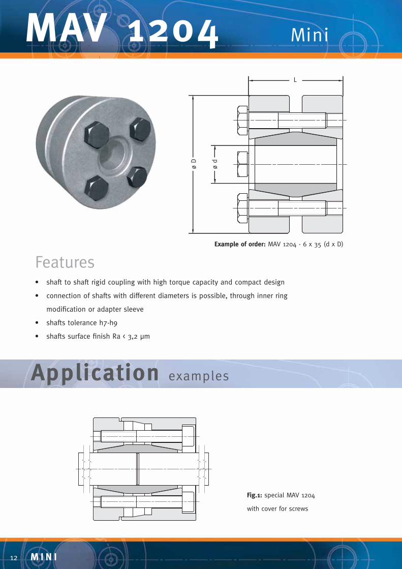
MAV 1204 Mini
ø D
L
ø d
Application examples
Features• shaft to shaft rigid coupling with high torque capacity and compact design
• connection of shafts with different diameters is possible, through inner ring
modifi cation or adapter sleeve
• shafts tolerance h7-h9
• shafts surface fi nish Ra < 3,2 μm
Example of order: MAV 1204 - 6 x 35 (d x D)
Fig.1: special MAV 1204
with cover for screws

M I N I 13
d x D L
mm
Ma Mt Fax
Nm Nm kN
Ps
N/mm² mm mm
6 x 35 19 M 5 4 27 9 491
7 x 35 19 M 5 4 31 9 421
8 x 35 19 M 5 4 36 9 368
9 x 39 23 M 5 4 50 11 327
10 x 39 23 M 5 4 55 11 294
11 x 39 23 M 5 4 61 11 268
12 x 44 30 M 5 4 80 13 226
13 x 44 30 M 5 4 87 13 209
14 x 44 30 M 5 4 93 13 194
15 x 52 34 M 6 12 160 22 275
16 x 52 34 M 6 12 170 22 258
17 x 52 34 M 6 12 180 22 242
18 x 52 34 M 6 12 200 22 229
19 x 52 34 M 6 12 210 22 217
20 x 60 40 M 6 12 360 36 301
Mini MAV 1204
screws
inner ring
thrust rings
Components of MAV 1204
Composition• slotted inner ring
• two outer thrust rings
• set of hexagonal head cap screws,
grade 10.9 (size M5 grade 8.8)
Fig.2: two different shaft sizes connected with special MAV 1204 Fig.3: adapter sleeve system for MAV 1204
DIMENSIONS SCREWS
size

M I N I14
MAV 3008 Mini
ø d
s
ø dø D
L
Application examples
Features• two-part shrink disc for shaft - hollow shaft connection with high torque capacity
• single taper design
• medium bending moment capacity
• recommended for high speed applications
• shaft and hollow shaft surface fi nish Ra < 3,2 μm
Fig.1: MAV shrink disc 3008 used to mount
hollow shaft gearbox onto driven shaft
Example of order:
MAV 3008 – 12 x 35 (d x D)
M I N I 15
Mini MAV 3008
d s d x D L Ma Mt Fax Ps Ph
mm mm mm Nm Nm kN N/mm² N/mm²
9 12 x 35 11 M 5 5 21 4,6 122 301
10 40 7,9 188 301
11 14 x 38 11 M 5 5 29 5,3 114 258
12 51 8,4 167 258
13 16 x 41 15 M 6 12 96 14 200 308
14 132 18 239 308
15 18 x 44 15 M 6 12 121 16 190 274
16 159 19 220 274
17 20 x 47 15 M 6 12 146 17 179 247
18 186 20 203 247
19 172 18 145 235
20 24 x 50 18 M 6 12 218 21 165 235
21 267 25 184 235
24 297 24 137 205
25 30 x 60 20 M 6 12 352 28 150 205
26 412 31 162 205
28 563 40 169 234
30 36 x 72 22 M 8 30 714 47 187 234
31 722 46 177 234
34 734 43 135 215
35 44 x 80 24 M 8 30 831 47 144 215
36 933 51 153 215
38 1230 65 166 241
40 50 x 90 26 M 8 30 1490 74 180 241
42 1760 84 193 241
6-10 H6-j6 0,011
11-18 H6-j6 0,014
19-30 H6-j6 0,017
31-50 H6-h6 0,032
Composition• slotted inner ring, with integrated
push-off threads
• outer thrust ring
• set of hexagonal head cap screws,
grade 10.9 (size M5 grade 8.8)
screws
inner ring
outer ring
Components of MAV 3008
Ps: contact pressure on shaft
(diameter ds)
Ph: contact pressure on hollow
shaft (diameter d)
DIMENSIONS SCREWS
ISO
tolerance
gap
max
(mm)
size

M I N I16
MAV Locking Assemblies are ready for installation. Performances are based on the following conditions:
• Locking Assembly, shaft and hub bore oiled
• oiled screws
Installation1. If necessary clean and slightly oil the parts. Do not use MoS2 based grease or similar to
lubricate shaft, hub and Locking Assembly.
2. Disengage the rings by loosening the screws or, if necessary, by moving some of them into
the push-off threads of the inner ring. Relocate any screws used to separate the rings.
3. Set torque wrench to the indicated tightening torque Ma. Tighten the screws in a
crosswise pattern in several steps. For the last run, set the torque wrench 3-5% higher than
the indicated tightening torque.
4. Reset torque wrench to the specifi ed torque and make sure no screw can turn, otherwise
repeat the procedure from step 3.
Installation Instructions Mini Locking Assemblies
Removal1. Sequentially loosen all screws and
move the appropriate number into
all push-off threads of the inner
ring.
2. Tighten the screws in a crosswise
pattern in several steps until rings
disengage.
Before reinstalling of the unit, restore
all the conditions as described above.
Please contact MAV for any technical
support you might require.
tightening
screws
inner ring
outer ring
Components of MAV Locking Assembly
push-off
threads
slit
M I N I 17
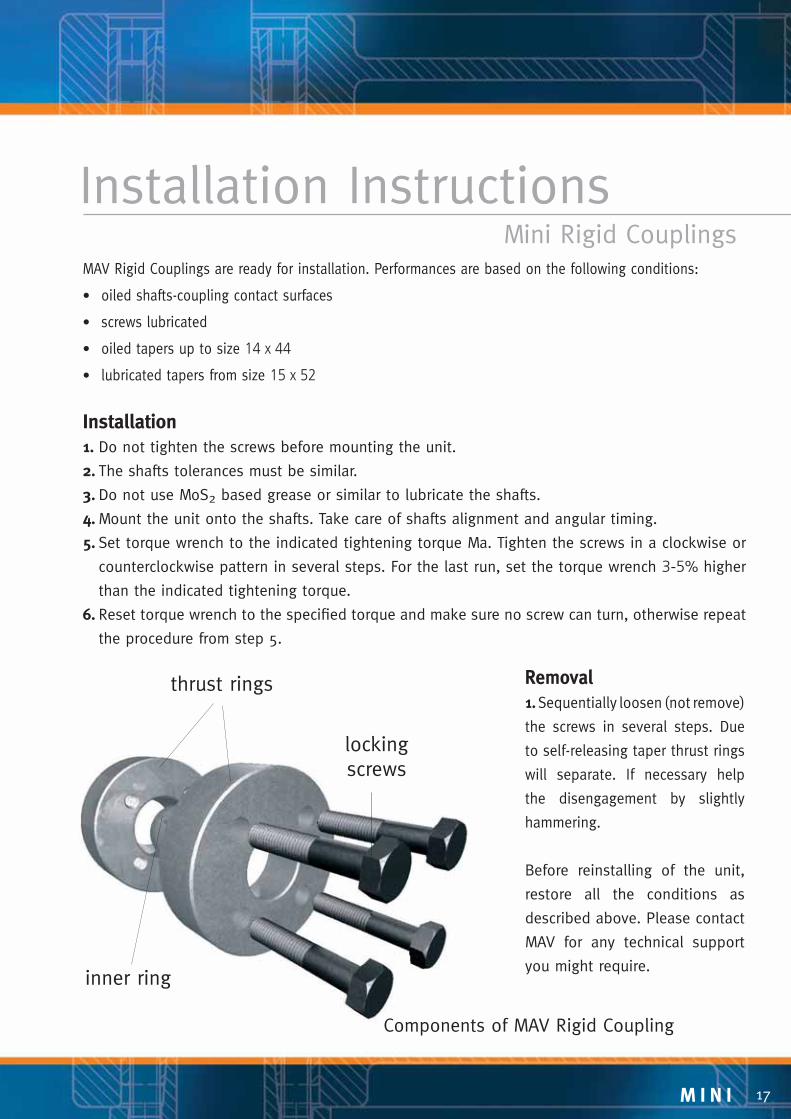
Installation InstructionsMini Rigid Couplings
inner ring
thrust rings Removal1. Sequentially loosen (not remove)
the screws in several steps. Due
to self-releasing taper thrust rings
will separate. If necessary help
the disengagement by slightly
hammering.
Before reinstalling of the unit,
restore all the conditions as
described above. Please contact
MAV for any technical support
you might require.
Components of MAV Rigid Coupling
MAV Rigid Couplings are ready for installation. Performances are based on the following conditions:
• oiled shafts-coupling contact surfaces
• screws lubricated
• oiled tapers up to size 14 x 44
• lubricated tapers from size 15 x 52
Installation1. Do not tighten the screws before mounting the unit.
2. The shafts tolerances must be similar.
3. Do not use MoS2 based grease or similar to lubricate the shafts.
4. Mount the unit onto the shafts. Take care of shafts alignment and angular timing.
5. Set torque wrench to the indicated tightening torque Ma. Tighten the screws in a clockwise or
counterclockwise pattern in several steps. For the last run, set the torque wrench 3-5% higher
than the indicated tightening torque.
6. Reset torque wrench to the specifi ed torque and make sure no screw can turn, otherwise repeat
the procedure from step 5.
locking
screws

M I N I18
Installation Instructions Mini Shrink Discs
Components of MAV Shrink Disc
Removal1. Remove dirt and rust from the hub
before dismantling the Shrink Disc.
2. Sequentially loosen (not remove)
the screws in several steps. Help
the disengagement using the push-
off threads.
Before reinstalling of the unit, restore
all the conditions as described above.
Please contact MAV for any technical
support you might require.
MAV Shrink Discs are ready for installation. Performances are based on the following conditions:
• indicated maximum shaft-hub clearance
• shaft-hub dry contact
• screws lubricated
• oiled tapers
Installation1. Clean and oil hub outer diameter and Shrink Disc bore prior to assembly. Do not tighten the
screws.
2. Clean carefully shaft and hub bore and mount hub onto shaft.
3. Set torque wrench to the indicated tightening torque Ma. Tighten the screws in a clockwise or
counterclockwise pattern in several steps. For the last run set the torque wrench 3-5% higher
than the indicated tightening torque.
4. Reset torque wrench to the specifi ed torque and make sure no screw can turn, otherwise repeat
the procedure from step 3.
locking
screws
inner ring outer ring
push-off
threads

M I N I 19
If you need technical assistance to select the right MAV Locking Device for your application,
please fi ll out this questionnaire and send it to us by fax using the following number:
+39 0461 84 51 50
Technical SupportData of application
Peak torque to be transmitted ........................Mt ______________ [Nm]
Peak axial force to be transmitted ................... Fax ______________ [kN]
Peak bending moment to be transmitted ........Mb ______________ [Nm]
Peak radial force to be transmitted ................. Fr _______________ [kN]
Maximum speed ............................................... n ________________ [1/min]
Operating temperature ..................................... To _______________ [°C]
Ambient temperature ........................................ Ta _______________ [°C]
SHAFT DATA:Size ................................................................... d ________________ [mm]
If hollow-shaft; inner diameter ......................... di _______________ [mm]
Material ............................................................. _________________
Yield point ........................................................ Rp0,2 ____________ [N/mm2]
HUB DATA:Outer diameter ................................................. dH ______________ [mm]
Length ............................................................... L ________________ [mm]
Material ............................................................. _________________
Yield point ........................................................ Rp0,2 ____________ [N/mm2]
Describe your application(if possible, please attach a sketch or a drawing)
______________________________________________________________________
______________________________________________________________________
______________________________________________________________________
______________________________________________________________________

MAV S.p.A. Via Venezia, 12 38049 Bosentino (TN) Italy Tel +39 0461 84 51 51 Fax +39 0461 84 51 50 www.mav.it [email protected]
Your local MAV distributor:M
09-E
NG
© 2
009
MAV S
.p.A
.