LOCATION PLANT VACUUM PUMP BIO VAC II / IV / SEC-...
6
Dear customer Congratulations. You have made a good choice when you decided to buy a GNATUS QUALITY product comparable to the best products available in the World. This manual is a general presentation of your product and it will give you important details We must also point out to you our chain of authorized dealers. Only dealers that make part of this chain will be able to keep your equipment constantly new for they count on technical assistants who have been trained and on spedific tools for the correct maintenance of your equipment. Doubts and information: GNATUS Call center (55-16) 2102-5000. Please, read it and keep this with you. ROOM AREA DIVISION 6-12 HOURS AXEL Divide the room in two areas: to the right and to the left of the dental chair. These areas are reserved to the dentist and his/her assistant respectively. AREA LIMITTED BY THE CIRCLE (A): It’s where everything is transferred to the patient’s mouth (the instruments and the tip of the hand pieces). This room should also have two stools. AREA LIMITED BETWEEN CIRCLES (A) AND (B): It’s the useful area that can be reached by the movements of a stretched arm. AREA LIMITED BETWEEN CIRCLES (B) AND (C): Sinks and cabinets are inside this area and once the drawers are open these should reach the area within circle (B). OPTION 2 OPTION 1 Directions to preparing the pre-installation of the dentist’s office In order to ensure the correct operation of the dentist’s office, we recommend that a qualified technician perform the pre-installation. For patient and operator safety and a perfect operation of the product, the installation of Gnatus dental clinics shall be performed in compliance with a grounding of about 10 Ω according to the Regulations NBR 5419/2005 e NBR 5410/2004. Thus, the dental clinics will operate properly and in compliance with safety standards established by NBR IEC, which Gnatus equipment were tested and approved by INMETRO. Any damage to the equipment caused by a failure (electrical, hydraulic or pneumatic) in the pre-installation will not be covered by the warranty. THEREFORE, THE DENTAL OFFICE SHOULD HAVE NO MORE THAN 3 METERS WIDE TO BE ERGONOMIC. Dental set ergonomic installation To obtain the best office space distribution, the place must be chosen to provide comfort to the operator in order to obtain good productivity. For this reason the equipment installation must be done under the strict recommendations by the I.S.O.(International Standards Organization) and the I.D.F. (International Dental Federation). To asses the equipment installation the I.S.O./I.D.F. made as a standard to divide the room in areas (see illustration). To perform this division, imagine the face of a clock, trace the concentric circuits (A),(B),(C) with its radius of 0.5, 1.0, 1.5 meters respectively, considering the center as the patient’s mouth lying on the chair. Cautions when installing the compressed air We recommend that the air used to activate the equipment be filtered to avoid oil, humidity and solid particles be introduced in the interior of the it affecting important internal parts such as valves, etc. This procedure helps to maintain internal components and hand pieces in good shape. It’s very important to choose the compressor specifications well to assure the best possible performance of all the equipment. • Ideal working pressure for a Gnatus dental set = 80 PSI • Maximum air consuption of a Gnatus dental set = 80 l/min The well functioning and durability of the gnatus dental set are directly influenced by the pre-installation, which should done according to instructions in this plant. Leaf 01 PRE-INSTALLATION MANUAL TOP VIEW (MEASUREMENTS IN MILIMETERS) AREA VACUUM PUMP LOCATION OF CONNECTION POINTS Location of connection points The vacuum pump can be installed inside the dental office (BIO-VAC II E BIO-VAC SEC), in a room aside of the main working or in a room proper for the installation of machinery. It’s important that the room to be protected from humidity, direct exposure to the sun rays and with good ventilation. G - WATER - PVC tube welding acceptable Ø 20 mm, glove at the tip with tin plug of Ø 20 X 1/2 ” in contact with the floor connected to the water supply. H - SUCTION - PVC tube welding acceptable Ø 25 mm, glove at the tip with tin plug of Ø 25 x 3/4” in contact with the floor connected to the point “H” of the connection box. I - DRAINING - PVC tube welding acceptable Ø 40 mm, glove at the tip with tin plug of Ø 25 x 3/4” in contact with the floor connected to the inspection box (with a minimum decline of 2%). J – SUCTION CONTROLS – Flexible electro duct of Ø 20 mm ending at 50 mm above the floor with wires of 3 x 0,75 mm² (different colors), 200 mm above the electro duct connected to the point J of the connection box. BIO VAC IV / X-RAYS Voltage(V) Cable diameter (mm²) Distance (m) 127 2,5 Up to 20 127 4,0 Of 21 up to 40 220 2,5 Up to 50 BIO VAC II / SEC Voltage(V) Cable diameter (mm²) Distance (m) 127 2,5 Up to 30 127 4,0 Of 31 up to 50 220 2,5 Up to 50 LOCATION PLANT VACUUM PUMP BIO VAC II / IV / SEC- “EXTERNAL CONNECTION” ELECTRICAL INSTALLATION VACUUM PUMP BIO VAC II / IV / SEC AND X-RAYS The vacuum pump can be installed inside the dental office (BIO-VAC II E BIO-VAC SEC), in a room aside of the main working or in a room proper for the installation of machinery. It’s important that the room to be protected from humidity, direct exposure to the sun rays and with good ventilation. BIO-VAC SEC G-WATER - Dispensable point: Operating Dry System. Don’t consume water in its operation. I-DRAINING - Can be directly connected to common draining. It doesn’t return because it has gravity drainage, thus it doesn’t generate pressure in draining. ** ** ** ** POWER OUTLET – Wires of 3x2,5mm² (live wire/ground). Electrical installation orientation: To ensure a proper functioning of the Equipment, please be aware of the voltage and the wires diameter specified by factory. NOTES: • The distance specified on the table above is from the distribution box up to the installation of the equipment. • The diameter of the wires that feed the main distribution box must be larger than the ones specified above. EQUIPAMENTOS MÉDICO-ODONTOLÓGICOS LTDA. Rod. Abrão Assed, Km 53+450m CEP 14097-500 - Ribeirão Preto - S.P. - Brasil Fone (16) 2102-5000 - Fax (16) 2102-5001 C.N.P.J. 48.015.119/0001-64 - Insc. Est. 582.329.957.115 www.gnatus.com.br - e-mail: [email protected] Cód.300038800 Rev.12 Cód.51000000051 Rev.12 POWER RATING SYNCRUS DENTAL CHAIR GL/G4/G3 200 VA SYNCRUS DENTAL CHAIR GLX/G8 530 VA LED DENTAL LIGHT - 5 LEDs 60 VA PERSUS L DENTAL LIGHT 55 VA X-RAY TIMEX 70 E / SOMMO 1200 VA OPTILIGHT LD MAX 17 VA OPTILIGHT MAX 8 VA OPTILIGHT PRIME / COLOR 5 VA JET-SONIC 60 VA AMALGAMIX II 90 VA BIO-VAC IV 1650 VA BIO-VAC II 1100 VA BIO-VAC SEC 770 VA AUTOCLAVE BIOCLAVE 12L/ VELOX 1600VA AUTOCLAVE BIOCLAVE 21L 1700VA BIO AQUA WATER DISTILLER 750VA INTRA-ORAL CAMERA 14 VA AIR COMPRESSOR 40L 127/220V 830/1100VA AIR COMPRESSOR 65L 127/220V 1660/2200VA SEALER BIOPACK 127/220V 570/460VA ULTRASONIC CLEANER 2L 127/220V 150/160VA ULTRASONIC CLEANER 6L 127/220V 290/310VA
Transcript of LOCATION PLANT VACUUM PUMP BIO VAC II / IV / SEC-...

Dear customerCongratulations. You have made a good choice when you decided to buy a GNATUS QUALITY product comparable to the best products
available in the World. This manual is a general presentation of your product and it will give you important details We must also point out to you our chain of authorized dealers.
Only dealers that make part of this chain will be able to keep your equipment constantly new for they count on technical assistants who have been trained and on spedific tools for the correct maintenance of your equipment. Doubts and information: GNATUS Call center (55-16) 2102-5000.
Please, read it and keep this with you.
ROOM AREA DIVISION6-12 HOURS AXELDivide the room in two areas: to the right and to the left of the dental chair.These areas are reserved to the dentist and his/her assistant respectively.
AREA LIMITTED BY THE CIRCLE (A):It’s where everything is transferred to the patient’s mouth (the instruments and the tip of the hand pieces). This room should also have two stools.
AREA LIMITED BETWEEN CIRCLES (A) AND (B):It’s the useful area that can be reached by the movements of a stretched arm.
AREA LIMITED BETWEEN CIRCLES (B) AND (C):Sinks and cabinets are inside this area and once the drawers are open these should reach the area within circle (B).
OPTION 2
OPTION 1
Directions to preparing the pre-installation of the dentist’s officeIn order to ensure the correct operation of the dentist’s office, we recommend that a qualified technician perform the pre-installation.For patient and operator safety and a perfect operation of the product, the installation of Gnatus dental clinics shall be performed in compliance
with a grounding of about 10 Ω according to the Regulations NBR 5419/2005 e NBR 5410/2004. Thus, the dental clinics will operate properly and in compliance with safety standards established by NBR IEC, which Gnatus equipment were tested and approved by INMETRO.
Any damage to the equipment caused by a failure (electrical, hydraulic or pneumatic) in the pre-installation will not be covered by the warranty.
THEREFORE, THE DENTAL OFFICE SHOULD HAVE NO MORE THAN 3 METERS WIDE TO BE ERGONOMIC.
Dental set ergonomic installationTo obtain the best office space distribution, the place must be
chosen to provide comfort to the operator in order to obtain good productivity.
For this reason the equipment installation must be done under the strict recommendations by the I.S.O.(International Standards Organization) and the I.D.F. (International Dental Federation).
To asses the equipment installation the I.S.O./I.D.F. made as a standard to divide the room in areas (see illustration). To perform this division, imagine the face of a clock, trace the concentric circuits (A),(B),(C) with its radius of 0.5, 1.0, 1.5 meters respectively, considering the center as the patient’s mouth lying on the chair.
Cautions when installing the compressed air We recommend that the air used to activate the equipment be
filtered to avoid oil, humidity and solid particles be introduced in the interior of the it affecting important internal parts such as valves, etc. This procedure helps to maintain internal components and hand pieces in good shape.
It’s very important to choose the compressor specifications well to assure the best possible performance of all the equipment.
• Ideal working pressure for a Gnatus dental set = 80 PSI• Maximum air consuption of a Gnatus dental set = 80 l/min
The well functioning and durability of the gnatus dental set are directly influenced by the pre-installation, which should done according to instructions in this plant.
Leaf 01
PRE-INSTALLATION MANUAL
TOP VIEW(MEASUREMENTS IN MILIMETERS)
AREA
VACUUM
PUMP
LOCATION OF CONNECTION POINTSLocation of connection points The vacuum pump can be installed inside the dental office (BIO-VAC II E BIO-VAC SEC), in a room aside of the main working or in a room proper for the installation of machinery. It’s important that the room to be protected from humidity, direct exposure to the sun rays and with good ventilation.
G - WATER - PVC tube welding acceptable Ø 20 mm, glove at the tip with tin plug of Ø 20 X 1/2 ” in contact with the floor connected to the water supply.
H - SUCTION - PVC tube welding acceptable Ø 25 mm, glove at the tip with tin plug of Ø 25 x 3/4” in contact with the floor connected to the point “H” of the connection box.
I - DRAINING - PVC tube welding acceptable Ø 40 mm, glove at the tip with tin plug of Ø 25 x 3/4” in contact with the floor connected to the inspection box (with a minimum decline of 2%).
J – SUCTION CONTROLS – Flexible electro duct of Ø 20 mm ending at 50 mm above the floor with wires of 3 x 0,75 mm² (different colors), 200 mm above the electro duct connected to the point J of the connection box.
BIO VAC IV / X-RAYS
Voltage(V) Cable diameter (mm²) Distance (m)
127 2,5 Up to 20
127 4,0 Of 21 up to 40
220 2,5 Up to 50
BIO VAC II / SEC
Voltage(V) Cable diameter (mm²) Distance (m)
127 2,5 Up to 30
127 4,0 Of 31 up to 50
220 2,5 Up to 50
LOCATION PLANT VACUUM PUMP BIO VAC II / IV / SEC- “EXTERNAL CONNECTION”ELECTRICAL INSTALLATION VACUUM PUMP BIO VAC II / IV / SEC AND X-RAYSThe vacuum pump can be installed inside the dental office (BIO-VAC II E BIO-VAC SEC), in a room aside of the main working or in a room proper for the installation of machinery. It’s important that the room to be protected from humidity, direct exposure to the sun rays and with good ventilation.
BIO-VAC SECG-WATER - Dispensable point: Operating Dry System. Don’t consume water in its operation.
I-DRAINING - Can be directly connected to common draining. It doesn’t return because it has gravity drainage, thus it doesn’t generate pressure in draining.
**
**
**
**
POWER OUTLET – Wires of 3x2,5mm² (live wire/ground).
Electrical installation orientation:To ensure a proper functioning of the Equipment, please be aware of the voltage and the wires diameter specified by factory.
NOTES:• The distance specified on the table above is from the distribution box up to the installation of the equipment.• The diameter of the wires that feed the main distribution box must be larger than the ones specified above.
EQUIPAMENTOS MÉDICO-ODONTOLÓGICOS LTDA.Rod. Abrão Assed, Km 53+450m
CEP 14097-500 - Ribeirão Preto - S.P. - BrasilFone (16) 2102-5000 - Fax (16) 2102-5001
C.N.P.J. 48.015.119/0001-64 - Insc. Est. 582.329.957.115www.gnatus.com.br - e-mail: [email protected]
Cód.300038800 Rev.12Cód.51000000051 Rev.12
POWER RATING SYNCRUS DENTAL CHAIR GL/G4/G3 200 VA
SYNCRUS DENTAL CHAIR GLX/G8 530 VALED DENTAL LIGHT - 5 LEDs 60 VAPERSUS L DENTAL LIGHT 55 VAX-RAY TIMEX 70 E / SOMMO 1200 VA
OPTILIGHT LD MAX 17 VAOPTILIGHT MAX 8 VAOPTILIGHT PRIME / COLOR 5 VAJET-SONIC 60 VAAMALGAMIX II 90 VABIO-VAC IV 1650 VABIO-VAC II 1100 VABIO-VAC SEC 770 VAAUTOCLAVE BIOCLAVE 12L/ VELOX 1600VAAUTOCLAVE BIOCLAVE 21L 1700VABIO AQUA WATER DISTILLER 750VAINTRA-ORAL CAMERA 14 VA
AIR COMPRESSOR 40L 127/220V 830/1100VA
AIR COMPRESSOR 65L 127/220V 1660/2200VA
SEALER BIOPACK 127/220V 570/460VA
ULTRASONIC CLEANER 2L 127/220V 150/160VA
ULTRASONIC CLEANER 6L 127/220V 290/310VA

BIO-VAC IVThe maximum distance allowed between a BIO-VAC IV and only one dental set is 15 m. Installing the equipment within a distance above the recommended one could affect the equipment’s performance.Whenever installed between 04 dental sets the equipment should be placed in the middle. The dental set furthest away shouldn’t be over 5 m.
BIO-VAC IIThe maximum distance allowed between a BIO-VAC II and only one dental set is 5 m. Installing the equipment within a distance above the recommended one could affect the equipment’s performance.Whenever installed between 02 dental sets the equipment should be placed in the middle.
BIO-VAC SECThe maximum distance allowed between a BIO-VAC SEC and only one dental set is 7 m. Installing the equipment within a distance above the recommended one could affect the equipment’s performance.Whenever installed between 03 dental sets the equipment should be placed in the middle.
IMPORTANT: The dimensions and facilities are to an only clinic. For other situations to request the orientation of the authorized resale. GNATUS reserves the right to alter the specifications of its products without prior notice.
COMPRESSED AIR (POINT A)
01
0202
03
04
WATER (POINT G)
08
11
12
13
10
02
ELECTRICAL CONTROL OF THE ASPIRATORS BIO-VAC (POINT J)
09
0502
07
ELECTRICAL (POINT B)
0502
06
04
SEWER INDEPENDENT OF THE WATER UNIT (POINT D)
0214
15
16
1718
19
INDEPENDENT SEWER BIO-VAC(POINT I)
15
16
1718
20
INTERCONNECTION SUCTION WITH BIO-VAC (POINT H)
15
16
23
24
0220
SUCTION BIO-VAC (POINT H)
20 02
15
16
23
25
SEWER INDEPENDENT (POINT I)
1520
16
17 18 19
WATER (POINT G)
08
11
12
13
10
02
ELECTRICAL CONTROL OF THE ASPIRATORS BIO-VAC (POINT J)
09
0502
26
INTERNAL CONNECTION POINTS (CONNECTION BOX)
INTERNAL CONNECTION POINTS (BIO-VAC)
01 - Bio-Vac02 - Conection Box03 - Pvc Tube (Sucction)04 - Three Ducting Wire (Suction Controls)
CONNECTIONS FOR MORE THAN ONE DENTAL SET INSTALLATION PROCEDURE “KIT OUT BOX SOMMO X-RAYS”
Built-in Electrical connection in the electrical control box - Prepare the installation previously; the extender cable must be passed through the electrical control boxes, making the connection
previously prepared to interconnect the X-Rays (A) and the Kit Out Box (B).- Remove the finishing lid from the X-Rays command (01), then, using an 11mm drill make a hole in the delimited area as shown below
(C). Now, pass one of the extender cable ends (02) through the lid hole (C) performing the connection of it to the remote control output.- Connect the other end of the extender cable (03) to the command lid of the Kit Out Box (D);- Using a Philips screwdriver fixe the Out Box command lid (D) into the electrical control box by means of two crews (05 e 06). Finish the
procedure connecting by remote control (E).
D
Command lid
rear view
Extender cable
connection
B
A
05
06
02
01
03
E
C
Extender cable
Electrical
command
box
Hole for theextender cable
Extender cableconnection
*01 - Copper tube Ø1/4”*02 - Finished floor*03 - Compressed air supply*04 - 3 threads 2,5mm²*05 - Flexible corrugated electricaldute Ø20mm*06 - Power inlet*07 - Linked to the point J of Bio Vac 08 - Connection inlet water Ø1/2”*09 - 3 threads 0,75mm² (in different collors)*10 - Link water inlet*11 - Soldered glove and with plug of brass Ø20mm x 1/2”*12 - Soldered knee 90º Ø20mm*13 - Soldered PVC tube Ø20mm 14 - Supressed *15 - Soldered glove and with plug of brass Ø25mmx3/4”*16 - Soldered knee 90º Ø25mm*17 - Soldered plug of reduction far away*18 - Soldered PVC tube Ø40mm*19 - Inspection box 150x150x50mm 20 - Hose Adapter Ø3/4”*23 - Soldered PVC tube Ø25mm*24 - Linked with of point H da Bio-Vac*25 - Linked with of point H da caixa de ligação*26 - Linked with of point J da caixa de ligação
* Material not supplied by Gnatus
BIO-VAC SEC (TO THREE DENTAL SET)
MAXIMUM NUMBER OF DENTAL SET SUPPORTED BY DENTAL SETBIO-VAC SEC (3 )
MAXIMUM NUMBER OF DENTAL SET SUPPORTED BY DENTAL SETBIO-VAC lV (4 )
MAXIMUM NUMBER OF DENTAL SET SUPPORTED BY DENTAL SETBIO-VAC ll (2 )
BIO-VAC IV (TO FOUR DENTAL SET)
BIO-VAC II (TO TWO DENTAL SET)
01
0204
03
Nota: The positioning of the Out Box Kit can be followed as installation of X-rays.
14
14
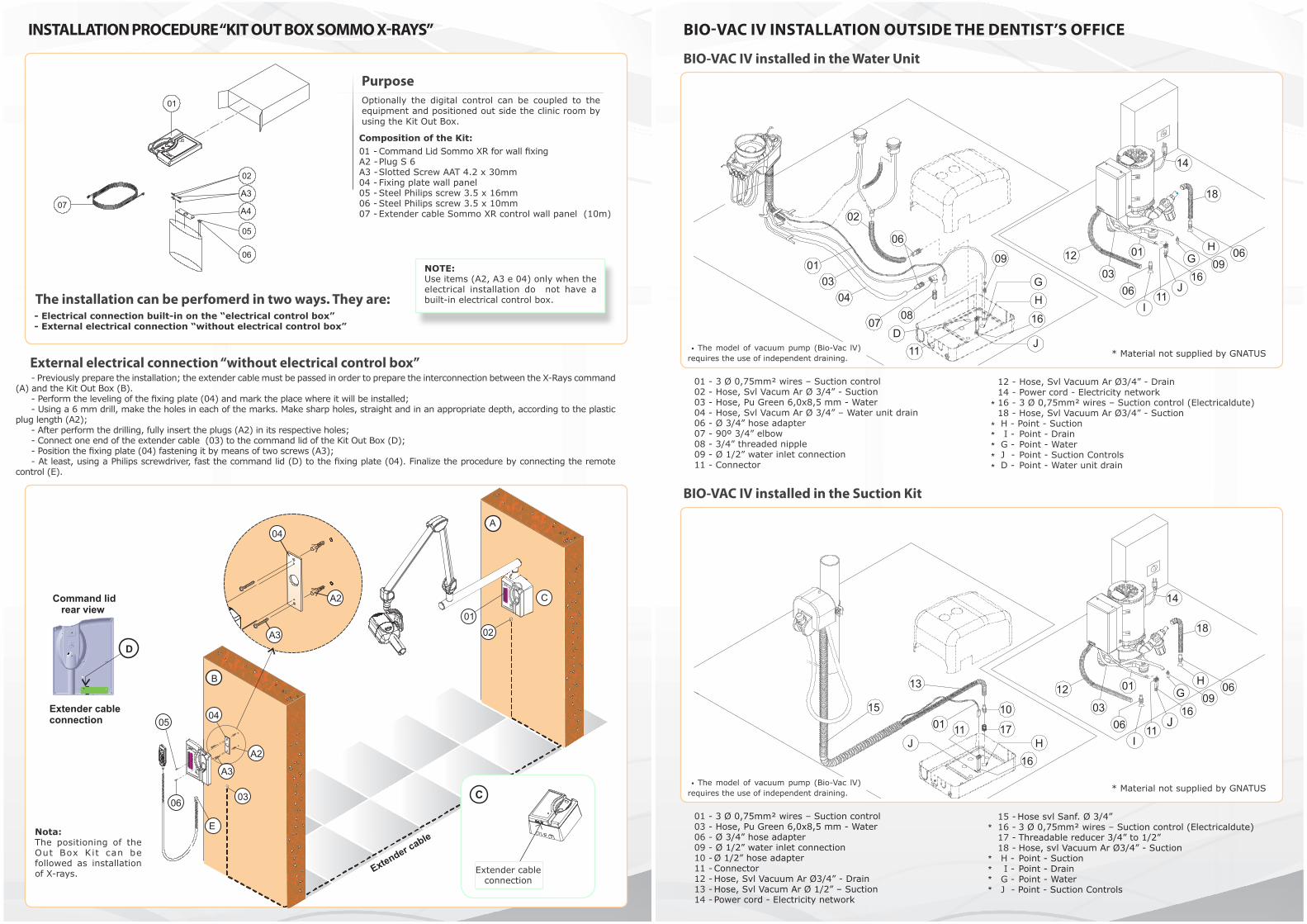
BIO-VAC IV installed in the Water Unit
BIO-VAC IV installed in the Suction Kit
1203
I
J11
GH
J17
H
13
15
110110
16
18
14
01
06
0609
16
01 - 3 Ø 0,75mm² wires – Suction control02 - Hose, Svl Vacum Ar Ø 3/4” - Suction03 - Hose, Pu Green 6,0x8,5 mm - Water04 - Hose, Svl Vacum Ar Ø 3/4” – Water unit drain06 - Ø 3/4” hose adapter07 - 90º 3/4” elbow08 - 3/4” threaded nipple09 - Ø 1/2” water inlet connection 11 - Connector
01 - 3 Ø 0,75mm² wires – Suction control03 - Hose, Pu Green 6,0x8,5 mm - Water06 - Ø 3/4” hose adapter09 - Ø 1/2” water inlet connection 10 - Ø 1/2” hose adapter11 - Connector12 - Hose, Svl Vacuum Ar Ø3/4” - Drain13 - Hose, Svl Vacum Ar Ø 1/2” – Suction 14 - Power cord - Electricity network
12 - Hose, Svl Vacuum Ar Ø3/4” - Drain14 - Power cord - Electricity network16 - 3 Ø 0,75mm² wires – Suction control (Electricaldute) 18 - Hose, Svl Vacuum Ar Ø3/4” - Suction H - Point - Suction I - Point - Drain G - Point - Water J - Point - Suction Controls D - Point - Water unit drain
15 - Hose svl Sanf. Ø 3/4” 16 - 3 Ø 0,75mm² wires – Suction control (Electricaldute) 17 - Threadable reducer 3/4” to 1/2”18 - Hose, svl Vacuum Ar Ø3/4” - Suction H - Point - Suction I - Point - Drain G - Point - Water J - Point - Suction Controls
BIO-VAC IV INSTALLATION OUTSIDE THE DENTIST’S OFFICE
18
14
12
03
01
06I
0609
16J
11
GH
J
16
HG
09
06
02
0103
04
0708
D11 * Material not supplied by GNATUS
* Material not supplied by GNATUS
*
*
*
****
****
INSTALLATION PROCEDURE “KIT OUT BOX SOMMO X-RAYS”
PurposeOptionally the digital control can be coupled to the equipment and positioned out side the clinic room by using the Kit Out Box.
The installation can be perfomerd in two ways. They are:- Electrical connection built-in on the “electrical control box”- External electrical connection “without electrical control box”
NOTE: Use items (A2, A3 e 04) only when the electrical installation do not have a built-in electrical control box.
Composition of the Kit:01 - Command Lid Sommo XR for wall fixingA2 - Plug S 6A3 - Slotted Screw AAT 4.2 x 30mm04 - Fixing plate wall panel05 - Steel Philips screw 3.5 x 16mm06 - Steel Philips screw 3.5 x 10mm07 - Extender cable Sommo XR control wall panel (10m)
External electrical connection “without electrical control box”- Previously prepare the installation; the extender cable must be passed in order to prepare the interconnection between the X-Rays command
(A) and the Kit Out Box (B).- Perform the leveling of the fixing plate (04) and mark the place where it will be installed;- Using a 6 mm drill, make the holes in each of the marks. Make sharp holes, straight and in an appropriate depth, according to the plastic
plug length (A2);- After perform the drilling, fully insert the plugs (A2) in its respective holes;- Connect one end of the extender cable (03) to the command lid of the Kit Out Box (D);- Position the fixing plate (04) fastening it by means of two screws (A3);- At least, using a Philips screwdriver, fast the command lid (D) to the fixing plate (04). Finalize the procedure by connecting the remote
control (E).
A
B
02
05
06
E
03
01
04
A2
A3
04
A2
A3
C
Extender cable
D
Command lid
rear view
Extender cable
connection
Extender cableconnection
A3
A4
Nota: The positioning of the Out Box Kit can be followed as installation of X-rays.
• The model of vacuum pump (Bio-Vac lV) requires the use of independent draining.
• The model of vacuum pump (Bio-Vac lV) requires the use of independent draining.

14
BIO-VAC II installed in the Water Unit
BIO-VAC II installed in the Suction Kit
01 - 3 Ø 0,75mm² wires – Suction control02 - Hose, Svl Vacum Ar Ø 3/4” - Suction03 - Hose, Pu Green 6,0x8,5 mm - Water04 - Hose, Svl Vacum Ar Ø 3/4” – Water unit drain05 - LL 3/4”- 1/2” reducer06 - Ø 3/4” hose adapter07 - 90º 3/4” elbow 08 - 3/4” threaded nipple
01 - 3 Ø 0,75mm² wires – Suction control03 - Hose, Pu Green 6,0x8,5 mm - Water06 - Ø 3/4” hose adapter09 - Ø 1/2” water inlet connection11 - Connector12 - Hose, Svl Vacuum Ar Ø3/4” - Drain
09 - Ø 1/2” water inlet connection11 - Connector12 - Hose, Svl Vacuum Ar Ø3/4” - Drain13 - Hose, Svl Vacuum Ar Ø 1/2” – Suction 14 - Power cord - Electricity network I - Point - Drain G - Point - Water D - Point - Water unit drain
13 - Hose, Svl Vacuum Ar Ø 1/2” – Suction 14 - Power cord - Electricity network15 - Hose Sve Sanf. Ø 3/4” I - Point - Drain G - Point - Water
BIO-VAC II INSTALLATION INSIDE THE DENTIST’S OFFICE
* Material not supplied by GNATUS
* Material not supplied by GNATUS
01
03
02 05
04
06 07
08I
D
G
09
1303
14
011211
06
15
G09
13
03
14
12
06
11
01
I
1301
*
*
*
*
*
“Wall Model” Scissors Arms X-Rays
“Wall Model” X-Rays
“Wall Model” Optilight CL Alcance
DIMENSIONS (MM)
• The model of vacuum pump (Bio-Vac ll) requires the use of independent draining.
• The model of vacuum pump (Bio-Vac ll) requires the use of independent draining.
To Wate
r Unit

BIO-VAC II installed in the Water Unit
BIO-VAC II installed in the Suction Kit
01 - 3 Ø 0,75mm² wires – Suction control02 - Hose, Svl Vacum Ar Ø 3/4” - Suction03 - Hose, Pu Green 6,0x8,5 mm - Water04 - Hose, Svl Vacum Ar Ø 3/4” – Water unit drain06 - Ø 3/4” hose adapter07 - 90º 3/4” elbow 08 - 3/4” threaded nipple09 - Ø 1/2” water inlet connection 10 - Ø 1/2” hose adapter11 - Connector
01 - 3 Ø 0,75mm² wires – Suction control03 - Hose, Pu Green 6,0x8,5 mm - Water06 - Ø 3/4” hose adapter09 - Ø 1/2” water inlet connection 10 - Ø 1/2” hose adapter11 - Connector12 - Hose, Svl Vacuum Ar Ø3/4” - Drain13 - Hose, Svl Vacum Ar Ø 1/2” – Suction14 - Power cord - Electricity network
12 - Hose, Svl Vacuum Ar Ø3/4” - Drain13 - Hose, Svl Vacuum Ar Ø 1/2” – Suction 14 - Power cord - Electricity network16 - 3 Ø 0,75mm² wires – Suction control (Electricaldute) 17 - Threadable reducer 3/4” to 1/2” H - Point - Suction I - Point - Drain G - Point - Water J - Point - Suction Controls D - Point - Water unit drain
15 - Hose svl Sanf. Ø 3/4” 16 - 3 Ø 0,75mm² wires – Suction control (Electricaldute)17 - Threadable reducer 3/4” to 1/2” H - Point - Suction I - Point - Drain G - Point - Water J - Point - Suction Controls
BIO-VAC II INSTALLATION OUTSIDE THE DENTIST’S OFFICE
* Material not supplied by GNATUS
* Material not supplied by GNATUS
I
06
12
14
03
1013
01
11
16
J G 09
H17
16
J1115
01
13
10
17G
H
01 03
02
04
06
07 08
I
D
06
12
14
03
1013
01
11
16
J G 09
H17
J 16H
G
1109
*
****
***
*
*
*
• The model of vacuum pump (Bio-Vac ll) requires the use of independent draining.
• The model of vacuum pump (Bio-Vac ll) requires the use of independent draining.
Installation on a wall of high resistance - concrete / stone / dense brick - “Using Bushes”
Installation on low resisteance wall - concrete block / pierced brick - “using Wall Kit (optional)”
CONDITIONS FOR PRE-INSTALLATION X-RAY WALL MOUNTED / OPTILIHT CL ALCANCE WALL MOUNTED
Specification of wall- To fasten the equipment the wall must withstand a load of 100 Kg and a traction force of 180 Kg at each point of fastening. - Above these conditions we recommend using the Wall Kit, applied in walls og low resistance “concrete block and pierced brick type”.
IMPORTANT: For fastening to Drywall walls, the weight of the product, the excess load and the place for fastening must be taken into consideration before yhe application.“Se the wall manufacture”.
NOTE: In order to install the Wall mounted X-Rays using the low resistance Wall Kit, proceed according to the information sheet which comes with the product.
Optional kit composed of:- 1 Plate for fastening (01);- 4 Staples (02) Used for fastening of the type bolted to the wall; - 4 Ties (03) Used for fastening of the layer type (fastening plate/control box);- 8 Nuts 3/8” (04) and 8 washers 3/8” (05).
Accompanies:- 4 AAT hexagonal head bolts (07)- 4 Plain steel washers 5/16” (08)- 4 Bushes S12 (09)
Power supply:Detail A - Eletrical connection embedded in the control boxEletrical passage box (11) must be positioned under the fastening plate in the area reserved for the embedded socket (06). Executive the installation respecting the dimensions.
Detail B - External electrical connection External electrical connection, with input power cable (10). “follow the product”
Sommo X-RaysChassis dimensional
Timex 70 E X-RaysChassis dimensional
02

BIO-VAC SEC installed in the Water Unit
BIO-VAC SEC installed in the Suction Kit
01 - 3 Ø 0,75mm² wires – Suction control02 - Hose, svl Vacum Ar Ø 3/4” - Suction03 - Hose, Pu Green 6,0x8,5 mm - Water04 - Hose, svl Vacuum Ar Ø 3/4” – Water unit drain06 - Ø 3/4” hose adapter07 - 90º 3/4” elbow 08 - 3/4” threaded nipple09 - Ø 1/2” water inlet connection 10 - Ø 1/2” hose adapter11 - Connector
01 - 3 Ø 0,75mm² wires – Suction control06 - Ø 3/4” hose adapter10 - Ø 1/2” hose adapter11 - Connector12 - Hose, svl Vacuum Ar Ø3/4” - Drain13 - Mangueira svl Vacuum Ar ø 1/2” - sucção 14 - Hose, svl Vacuum Ar Ø 1/2” – Suction
12 - Hose, svl Vacuum Ar Ø3/4” - Drain13 - Hose, svl Vacum Ar Ø 1/2” – Suction 14 - Power cord - Electricity network16 - 3 Ø 0,75mm² wires – Suction control17 - Threadable reducer 3/4” to 1/2” H - Point - Suction I - Point - Drain G - Point - Water J - Point - Suction Controls D - Point - Water unit drain
15 - Mangueira svl sanf. Ø 3/4” 16 - 3 Ø 0,75mm² wires – Suction control 17 - Threadable reducer 3/4” to 1/2” H - Point - Suction I - Point - Drain J - Point - Suction Controls
BIO-VAC SEC INSTALLATION OUTSIDE THE DENTIST’S OFFICE
* Material not supplied by GNATUS
01 0304
07 08
0206
09
14
0112
H17
1013
06
11
16
J
I
11
G
H16J
D
01
13
10
1715
06
14
H17
1013
11
1201
16
J
I
11
H
16
J
*
*
***
***
*
*
BIO-VAC SEC installed in the Water Unit
01 - 3 Ø 0,75mm² wires – Suction control02 - Hose, svl Vacum Ar Ø 3/4” - Suction03 - Hose, Pu Green 6,0x8,5 mm - Water04 - Hose, svl Vacum Ar Ø 3/4” – Water unit drain05 - LL 3/4”- 1/2” reducer06 - Ø 3/4” hose adapter07 - 90º 3/4” elbow08 - 3/4” threaded nipple
09 - Ø 1/2” water inlet connection11 - Connector12 - Hose, slv Vacuum Ar Ø3/4” - Drain13 - Hose, slv Vacuum Ar Ø 1/2” – Suction 14 - Power cord - Electricity network18 - T Connection 3/4 “ drain hose adapter G - Point - Water D - Point - Water unit drain
BIO-VAC SEC INSTALLATION INSIDE THE DENTIST’S OFFICE
01
02 05
0304
0618
07 08
D
G
09
13
01
14
1211
*
BIO-VAC SEC installed in the Suction Kit
01 - 3 Ø 0,75mm² wires – Suction control06 - Ø 3/4” hose adapter11 - Connector12 - Hose, svl Vacuum Ar Ø3/4” - Drain
13 - Hose, svl Vacum Ar Ø 1/2” – Suction 14 - Power cord - Electricity network15 - Hose svl Sanf. Ø 3/4” I - Point - Drain
* Material not supplied by GNATUS
01
15 13
13
01
14
12
11
06
I
*
*
• Although we recommend the use of independent draining, this model of vacuum pump (Bio-Vac Sec) releases the use of independent draining.* Material not supplied by GNATUS
• Although we recommend the use of independent draining, this model of vacuum pump (Bio-Vac Sec) releases the use of independent draining. * Material not supplied by GNATUS
• Although we recommend the use of independent draining, this model of vacuum pump (Bio-Vac Sec) releases the use of independent draining.
• Although we recommend the use of independent draining, this model of vacuum pump (Bio-Vac Sec) releases the use of independent draining.