Location-Aware Distributed Clustering with Eliminating GPS ...
13
Location-Aware Distributed Clustering with Eliminating GPS in Vehicular Ad-hoc Networks Samaneh Beheshti Department of Computer Engineering, North Tehran Branch, Islamic Azad University, Tehran, Iran [email protected] Sahar Adabi Department of Computer Engineering, North Tehran Branch, Islamic Azad University, Tehran, Iran [email protected] Ali Rezaee Department of Computer Engineering, Science and Research Branch, Islamic Azad University, Tehran, Iran [email protected] Abstract— Vehicular ad-hoc network (VANET) is a type of mobile network which is used for establishing connection between vehicles (M2M) and also between vehicles and nearby stationary equipment which are often road-side equipment. The main target of VANET is to provide security and convenience for the passengers. In order to achieve this goal, a special electronic device called OBU (On-Board Unit) is embedded in each vehicle which makes the connection between vehicles and between the vehicles and the road-side equipment possible. In this paper, the Location- Aware Clustering in Vehicular Ad-hoc Networks (LAC-VANET) is proposed. We try to achieve the main and major goal in VANET networks, i.e. fast propagation of security and urgent messages in ITS systems, using clustering and selecting the best cluster head based on Fuzzy logic such that the cluster head can transfer important information such as the obstacles and accidents detected on the road with a suitable speed and without creating a large traffic load in the vehicle network in order to notify other vehicles and prevent the danger and vehicle accidents. Moreover, LAC-VANET method is evaluated here via extensive simulations carried out in NS-2. The simulation results indicate that the VANET network performance metrics are improved in terms of average throughput, Packet Delivery Ratio (PDR), end to end delay, and packet loss rate. Keywords- Vehicular ad-hoc network (VANET); M2M; Fuzzy logic; ITS; LAC-VANET I. INTRODUCTION Vehicular Ad Hoc Networks (VANETs) are special class of Mobile Ad Hoc Networks (MANETs). Unlike the MANET nodes, VANET nodes move very fast. Maintaining a steady and stable path for the release of urgent and alert messages from a danger zone is a very challenging task. The main target of VANET is to provide security and convenience for the passengers. In order to achieve this goal, a special electronic device called OBU (On-Board Unit) is embedded in each vehicle which makes the connection between vehicles and between the vehicles and the road-side equipment. possible. Such a network must be implemented without the limitations of client-server network connection structures [1]. Each vehicle equipped with a VANET device is similar to a node in Ad-hoc networks and will be able to send and receive others’ messages through the wireless network. Traffic alerts, road signs, and online traffic monitoring which can be transferred through such a network give the driver the tools needed for making decisions about the best route. Since creating an inter-vehicle ad hoc network is associated with deadly and vital conditions, the quick transmission of security messages in this network is of utmost importance. Therefore, intelligent transportation systems (ITS) were created. The ITS system is a distributed system which is connected to the vehicles, road-side-units (RSU), and the user’s mobile phone and together they run the application services developed and managed by the software providers. All of the computational and control functions of the vehicle are managed by displaying information on a display or changing the speed of the vehicle. Therefore, communications in a vehicle are a necessary and important part of ITS. In its simplest format, vehicles are connected to the servers remotely and a there must be a wireless interface like mobile network or satellite connection for establishing the connection remotely. Data propagation in VANETs is used for improving the driving quality in terms of time, distance, and safety. There are various methods for optimizing V2V Preprints (www.preprints.org) | NOT PEER-REVIEWED | Posted: 30 January 2020 doi:10.20944/preprints202001.0367.v1 © 2020 by the author(s). Distributed under a Creative Commons CC BY license.
Transcript of Location-Aware Distributed Clustering with Eliminating GPS ...

Location-Aware Distributed Clustering with
Eliminating GPS in Vehicular Ad-hoc
Networks
Samaneh Beheshti
Department of Computer
Engineering, North Tehran
Branch, Islamic Azad University,
Tehran, Iran
Sahar Adabi
Department of Computer
Engineering, North Tehran
Branch, Islamic Azad University,
Tehran, Iran
Ali Rezaee
Department of Computer
Engineering, Science and Research
Branch, Islamic Azad University,
Tehran, Iran
Abstract— Vehicular ad-hoc network (VANET) is a type of mobile network which is used for establishing connection
between vehicles (M2M) and also between vehicles and nearby stationary equipment which are often road-side
equipment. The main target of VANET is to provide security and convenience for the passengers. In order to achieve
this goal, a special electronic device called OBU (On-Board Unit) is embedded in each vehicle which makes the
connection between vehicles and between the vehicles and the road-side equipment possible. In this paper, the Location-
Aware Clustering in Vehicular Ad-hoc Networks (LAC-VANET) is proposed. We try to achieve the main and major
goal in VANET networks, i.e. fast propagation of security and urgent messages in ITS systems, using clustering and
selecting the best cluster head based on Fuzzy logic such that the cluster head can transfer important information such
as the obstacles and accidents detected on the road with a suitable speed and without creating a large traffic load in the
vehicle network in order to notify other vehicles and prevent the danger and vehicle accidents. Moreover, LAC-VANET
method is evaluated here via extensive simulations carried out in NS-2. The simulation results indicate that the VANET
network performance metrics are improved in terms of average throughput, Packet Delivery Ratio (PDR), end to end
delay, and packet loss rate.
Keywords- Vehicular ad-hoc network (VANET); M2M; Fuzzy logic; ITS; LAC-VANET
I. INTRODUCTION
Vehicular Ad Hoc Networks (VANETs) are special class of Mobile Ad Hoc Networks (MANETs). Unlike the MANET nodes, VANET nodes move very fast. Maintaining a steady and stable path for the release of urgent and alert messages from a danger zone is a very challenging task. The main target of VANET is to provide security and convenience for the passengers. In order to achieve this goal, a special electronic device called OBU (On-Board Unit) is embedded in each vehicle which makes the connection between vehicles and between the vehicles and the road-side equipment. possible. Such a network must be implemented without the limitations of client-server network connection structures [1]. Each vehicle equipped with a VANET device is similar to a node in Ad-hoc networks and will be able to send and receive others’ messages through the wireless network. Traffic alerts, road signs, and online traffic monitoring which can be transferred through such a network give the driver the tools needed
for making decisions about the best route. Since creating an inter-vehicle ad hoc network is associated with deadly and vital conditions, the quick transmission of security messages in this network is of utmost importance. Therefore, intelligent transportation systems (ITS) were created. The ITS system is a distributed system which is connected to the vehicles, road-side-units (RSU), and the user’s mobile phone and together they run the application services developed and managed by the software providers. All of the computational and control functions of the vehicle are managed by displaying information on a display or changing the speed of the vehicle. Therefore, communications in a vehicle are a necessary and important part of ITS. In its simplest format, vehicles are connected to the servers remotely and a there must be a wireless interface like mobile network or satellite connection for establishing the connection remotely. Data propagation in VANETs is used for improving the driving quality in terms of time, distance, and safety. There are various methods for optimizing V2V
Preprints (www.preprints.org) | NOT PEER-REVIEWED | Posted: 30 January 2020 doi:10.20944/preprints202001.0367.v1
© 2020 by the author(s). Distributed under a Creative Commons CC BY license.

connections. Clustering is one of them. In clustered vehicles, the same vicinity gets grouped together in order to establish an efficient connection. Clustering can be used for improving scalability and routing reliability in VANETs. A sample vehicular ad-hoc network is shown in Fig. I.
FIGURE I. VEHICULAR AD-HOC NETWORK.
In this paper, we try to achieve the main and major goal in VANET networks, i.e. fast propagation of security and urgent messages in ITS systems, using clustering and selecting the best cluster head based on Fuzzy logic such that the cluster head can transfer important information such as the obstacles and accidents detected on the road with a suitable speed and without creating a large traffic load in the vehicle network in order to notify other vehicles and prevent the danger and vehicle accidents.
The paper presented here is organized as the following. Section II presents the related works on location-aware distributed clustering. In Section III, the details of our proposed LAC-VANET method is discussed. Moreover, parameters utilized for performance evaluation are investigated and simulation results are discussed in Section IV. Finally, in Section V, the paper is concluded.
II. RELATED WORKS
One of the most challenging issues of VANETs is routing. The dynamic nature of VANETs, which is due to high velocity and movement limitations (due to special traffic conditions on the road) of vehicles, has led to the fact that MANET’s routing protocols have been proven useless and insufficient for VANETs. Some of the researches activities in the context of developing a routing algorithm for VANETs are presented in this section. The work presented in [2] proposes an efficient routing protocol named AHP-based Multi metric Geographical Routing Protocol (AMGRP) as it adopts an Analytical Hierarchical Process (AHP) while considering multiple routing criteria such as mobility metric, link lifetime, node density and node status which have been accepted as crucial factors for better performance of a protocol. The protocol implements the computed single-weighing function to identify a next hop node within a defined range which can ensure an enhanced forwarding process.
The work presented in [3] introduces a Reliable Routing Protocol (R2P) for Vehicular Ad-hoc Networks (VANETs), which divides the network into overlapping zones. For each zone, a special node is promoted to be the Master Node (MN), which maintains an up-to-date routing boards for inter/intra-zone communication. R2P depends on two types of boards, namely; Internal Routing Board (IRB) and External Routing Board (ERB). Two types of IRB are used, namely; Zone Routing Board (ZRB) that is maintained by MNs, and Private Routing Board (PRB) that is maintained by each network node. Both ZRB and PRB register routes among zone nodes, while ERB, which is maintained by MN, registers available gateways to neighboring zones.
In [4], a reliable multi-level routing protocol based on clustering, RMRPTS has been introduced in VANETs. Even if this topology constantly changes, clustering based multi-level routing will create the possibility of self-organization and route maintaining; moreover, it will solve the problem of developing a trap in the local optimum using TABU search. At the first level, the proposed protocol is an extension of AODV routing protocol that has been improved using fuzzy logic in order to create reliable routing between cluster members. TABU search has been used at a higher level for routing between cluster heads and destination. TABU search is a meta-heuristic improved learning method used for solving hybrid optimization problems, and it uses cost function to select a solution among a set of possible solutions. The effective parameters used in the proposed method to select the best path include nodes distance, the velocity of nodes, node’s angle, link stability, and link reliability.
In [5], authors proposed PFQ-AODV, which is a portable VANET routing protocol that learns the optimal route by employing a fuzzy constraint Q-learning algorithm based on ad hoc on-demand distance vector (AODV) routing. The protocol uses fuzzy logic to evaluate whether a wireless link is good or not by considering multiple metrics, which are, specifically, the available bandwidth, link quality, and relative vehicle movement. Based on an evaluation of each wireless link, the proposed protocol learns the best route using the route request (RREQ) messages and hello messages. The protocol can infer vehicle movement based on neighbor information when position information is unavailable. PFQ-AODV is also independent of lower layers. Therefore, PFQ-AODV provides a flexible, portable, and practicable solution for routing in VANETs.
In [6], a graph-based reliable routing scheme for VANETs has been proposed to facilitate QoS support in routing process. In this routing development graph, Dijkstra’s algorithm was expanded to find the most reliable path in the VANET-oriented evolving graph.
In [7], a link reliability mathematical model, which considers not only the impact of the link duration, but also traffic density, was designed and presented. The aim of DeReQ algorithm is to find a route which is not only reliable, but also compliant with delay requirements. Adaptive QoS-based routing for VANETs using ACO sought to set up the best QoS route with a delay constraint from a source vehicle to
Preprints (www.preprints.org) | NOT PEER-REVIEWED | Posted: 30 January 2020 doi:10.20944/preprints202001.0367.v1

its destination in terms of three QoS metrics, namely, connectivity probability, packet delivery rate and delay.
In [8], an ACO and fuzzy logic-based approach has been proposed for enhanced framework in vehicular ad-hoc networks, which can present a high data packet delivery ratio and low end-to-end delay.
Souze et al. [9] have proposed the multicast with ant colony optimization for VANETs based on MAODV (MAV-AODV) protocol. This protocol, which inspired the principles of the ant colony optimization, builds stable trees base on vehicular mobility information. MAV-AODV protocol evaluates the route stability and estimates the link lifetime by using beacon messages. This mobility information is used to define the procedures for the route request to the multicast tree and for the multicast route reply. This protocol uses two types of messages: route request message (Ant-RREQ-J) and reply message (Ant-RREP) and builds the multicast tree by using paths with longer lifetime and smaller hop counts. Choosing these paths depends on the number of pheromones deposited by routing messages that function as ants. The simulation results represented that MAV-AODV is better than MAODV in terms of several metrics such as packet delivery ratio, maximum end-to-end delay and routing overhead.
III. THE PROPOSED LAC-VANET METHOD
In the following section, we design a Location-Aware Distributed Clustering schema by employing the Fuzzy Logic System. The proposed system consists of three steps, such as the assumptions in the LAC-VANET method is discussed in Sect, A. Next section defines the steps of the proposed LAC-VANET method. Section C describes performing re-clustering and selecting the new cluster head.
A. The Assumptions in the LAC-VANET Method
The proposed method is for urban areas and non-urban areas which have inter-vehicle facilities. Some of the assumptions of the proposed method are presented below:
• In the proposed LAC-VANET method, it is assumed that the vehicles are not equipped with GPS.
• In the proposed LAC-VANET method, it is assumed that the vehicles are equipped with OBU.
• Each vehicle sends its location in a HELLO message after discovering its information so that the vehicles in the cluster send the packets to each other.
• Each vehicle has a specific transmission range and can receive a data message from another vehicle only in case it is in the range of that vehicle. Range of each vehicle is
presented with a green circle in Fig. II.
FIGURE II. TRANSMISSION RANGE IN THE PROPOSED METHOD
B. Steps of the Proposed LAC-VANET Method
Our proposed LAC-VANET method consists of three phases: the first phase is the acquisition of the location information of each vehicle, the second phase is the propagation of information to neighboring vehicles in the network, and the third phase is selecting the cluster head and transmitting data using Fuzzy logic. The formation of the network in the proposed method in the ITS system is presented in Figure II. The green circle around each vehicle shows the transmission range of the vehicles. We mentioned that the vehicles are not equipped with a global positioning system (GPS) device. Therefore, we act as phase one in order to obtain the location of each vehicle.
1) Phase One: Discovering Vehicle Position In the proposed method, the vehicles are not
equipped with GPS. Therefore, each vehicle obtains its position from RSU based on the received signal strength (RSSI). The procedure is such that periodic messages are exchanged between the OBU device on the vehicle and the RSUs on the road. An OBU device scans all the messages in the range it can detect. Then, selects one of the RSUs for joining. In fact, RSU collects the RSSI values and generates the RSSI data according to the current location of the vehicle. All of the measured radio signal strength values and also the radio signal propagation loss model are used while calculating RSSI for obtaining the correct position.
Assuming the transmitted signal strength to be TXP and
the route drop model to be C and the route drop
coefficient to be α, the receiving RSU can use the
received signal power ( RECVP ) to calculate the distance
( VDi ) between itself and the transmitter vehicle. The
calculation can be carried out using Eq. (1).
* TX TXRECV V
V RECV
P cPP c Di
Di P= =
(1)
This method does not need any extra hardware and also the distance is obtained easily and without the need for coordination and transmission of extra signals. Therefore, it seems to be a suitable method. Although RSSI values are not constant and the received power value is variable, but the error can be reduced by sending the message repeatedly. Therefore, the RSU can calculate the position of the vehicle using Eq. (2)
with respect to its fixed position ( ,i iX Y ) and inform the
OBU.
Preprints (www.preprints.org) | NOT PEER-REVIEWED | Posted: 30 January 2020 doi:10.20944/preprints202001.0367.v1
( ) ( )2 2
V i j i jDi X X Y Y= − + −
(2)
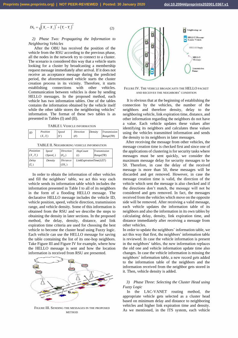
2) Phase Two: Propagating the Information to
Neighboring Vehicles After the OBU has received the position of the
vehicle from the RSU according to the previous phase, all the nodes in the network try to connect to a cluster. The scenario is considered this way that a vehicle starts looking for a cluster by broadcasting a membership request message immediately after arrival. If it does not receive an acceptance message during the predicted period, the aforementioned vehicle starts the cluster creation process in its vicinity. Therefore, it starts establishing connections with other vehicles. Communication between vehicles is done by sending HELLO messages. In the proposed method, each vehicle has two information tables. One of the tables contains the information obtained by the vehicle itself while the other table stores the neighboring vehicles’ information. The format of these two tables is as presented in Tables (I) and (II).
TABLE I. VEHICLE INFORMATION
ID ( , )i i
Position
X Y
( )
Speed
V
( )
Direction
Density ( )
Transmission
Range TR
TABLE II. NEIGHBORING VEHICLE INFORMATION
( , )j j
Posiotion
X Y
( )V
Speed
Speed
( )ID
Direction
( )
HopCount
t
( )
Transmission
Range TR
( )V
Delay
T
Density tan
( )V
Dis ce
DI
( )LinkExpirationTime LET
In order to obtain the information of other vehicles
and fill the neighbors’ table, we act this way each
vehicle sends its information table which includes the
information presented in Table I to all of its neighbors
in the form of a flooding HELLO message. The
declarative HELLO message includes the vehicle ID,
vehicle position, speed, vehicle direction, transmission
range, and vehicle density. Some of this information is
obtained from the RSU and we describe the steps to
obtaining the density in later sections. In the proposed
method, the delay, density, distance, and link
expiration time criteria are used for choosing the best
vehicle to become the cluster head using Fuzzy logic.
Each vehicle can use the HELLO message for saving
the table containing the list of its one-hop neighbors.
Take Figure III and Figure IV for example, where how
the HELLO message is sent and how the location
information is received from RSU are presented.
FIGURE III. SENDING THE MESSAGES IN THE PROPOSED
METHOD
FIGURE IV. THE VEHICLE BROADCASTS THE HELLO PACKET
AND RECEIVES THE NEIGHBORS’ CONDITION
It is obvious that at the beginning of establishing the
connection by the vehicles, the number of the
neighbors and therefore density, delay to the
neighboring vehicle, link expiration time, distance, and
other information regarding the neighbors do not have
a value. Each vehicle updates these values after
identifying its neighbors and calculates these values
using the vehicles transmitted information and sends
the density to its neighbors in later messages.
After receiving the message from other vehicles, the
message creation time is checked first and since one of
the applications of clustering is for security tasks where
messages must be sent quickly, we consider the
maximum message delay for security messages to be
50. Therefore, in case the delay of the received
message is more than 50, these messages will be
discarded and get removed. However, in case the
message creation time is valid, the direction of the
vehicle which sent the message is also checked and if
the directions don’t match, the message will not be
considered and gets removed. In fact, the messages
received from the vehicles which move on the opposite
side will be removed. After receiving a valid message,
each vehicle updates the information table of its
neighbors and also the information in its own tables by
calculating delay, density, link expiration time, and
distance immediately after receiving a message from
other vehicles.
In order to update the neighbors’ information table, we
act this way that first, the neighbors’ information table
is reviewed. In case the vehicle information is present
in the neighbors’ tables, the new information replaces
the old one and vehicle information update time also
changes. In case the vehicle information is missing the
neighbors’ information table, a new record gets added
to the information table of the neighbors and the
information received from the neighbor gets stored in
it. Then, vehicle density is added.
3) Phase Three: Selecting the Cluster Head using
Fuzzy Logic
In the LAC-VANET routing method, the
appropriate vehicle gets selected as a cluster head
based on minimum delay and distance to neighboring
vehicles and higher link expiration time and density.
As we mentioned, in the ITS system, each vehicle
Preprints (www.preprints.org) | NOT PEER-REVIEWED | Posted: 30 January 2020 doi:10.20944/preprints202001.0367.v1

seeks its current location information from RSU using
OBU. This information is calculated using RSSI and
using the information received from the neighbors, it
calculates the density, distance, delay, and link
expiration time between itself and the neighbor. In the
proposed LAC-VANET method, the cluster head gets
selected as the most appropriate cluster head for
transmitting the information packet based on criteria
like lower delay, shorter distance to the neighbors,
higher density, and link with longer expiration time.
After receiving the reports, the condition of the
neighbors, and receiving the information of
neighboring vehicles, each node calculates the delay
VT , distance (VDi ), link expiration time (LET), and
density for each neighbor as follows (V is short for
Vehicular meaning a vehicle)
Delay: Represents the time required for a vehicle with
a unique identification number for packet delivery to
the intended destination, calculated using Eq. (3).
Distance indicates the distance between the neighbor
vehicle and the destination which is obtained using Eq.
(2) and is also the speed related to neighboring
vehicles.
* TX TXRECV V
V RECV
P cPP c Di
Di P= =
(3)
Table III, for example, presents the condition where a
vehicle has five other vehicles in its communication
range. Vehicles A, B, C, D, and F for example. Delay
for each vehicle is calculated in Table III. In the
proposed LAC-VANET method, unlike other methods
where only the vehicle speed is used as the criterion for
choosing the vehicle, the criteria for selecting the
cluster head for quick propagation of information is the
delay to the destination, density, distance, and link
expiration time between neighboring vehicles. The
lower the delay of a node is, that node is more suited
for becoming the cluster head.
TABLE III. CALCULATING THE DELAY
Vehicle Distance(m) Speed(m/sec) Delay (T)
A 550 50 11
B 600 50 12
C 500 45 11
D 700 50 14
F 400 40 10
Link Expiration Time (LET): the next criterion used
as an input for the Fuzzy logic is the link expiration
time (LET). The link expiration time is the amount of
time when two mobile nodes can stay in touch with
each other. In order to evaluate LET in the proposed
method, we use important criteria used in inter-vehicle
like speed, movement direction, position, etc. This
information is obtained using the information
exchanged in the HELLO message and are available in
the neighbors’ table. LET is calculated using Eq. (4).
( ) ( ) ( )22 2 2
2 2
*ab cd a c r ad bcLET
a c
− + + + − −
= +
(4)
LET is the link expiration time and parameters a, b, c,
and d in Eq. (4) are obtained as follows:
cos cos
sin sin
i i j j
i j
i i j j
i j
a V V
b x x
c V V
d y y
= −
= −
= −
= −
i and j are two moving vehicles which have a
transmission range of (TR) meters.iV and
jV are these
two vehicles’ velocities whilei and
j represent their
movement direction. Also,iX ,
jX andiY ,
jY represent
their position. The higher the link expiration time
between two nodes is, the more suited that node is
because its connection links get destroyed later.
Distance (VDi ): the distance parameter presents the
overall distance of a node with its neighbors. The lower
this distance is, the node is more appropriate for
becoming the cluster head because it leads to a
decrease in delay and faster transmission of packets to
its neighbors. The distance criterion is described based
on the information in the neighbors’ table obtained
from the neighbors and the position of the vehicle,
using Eq. (2).
Density: Displays the number of neighbors in the
transfer range at the time the current HELLO message
is sent. The density is meant to be the number of
vehicles that are located in the neighborhood of the
node when HELLO message is sent, which is
calculated as the number of vehicles in the
neighborhood list of each node at the moment of
sending a HELLO message, divided by the transfer
range of the node. The neighbors list is made up of
vehicles in the transfer range that send HELLO packets
with high power, which these neighbors are considered
as stable neighbors. Each node calculates its current
density and puts it in the next HELLO message. The
Density is calculated in Eq. (5) follows:
( )( )ID
ID
Nnig tDensity t
TR=
(5)
Based on Eq. (5), when a node has a higher density than
other nodes, it is better option to choose, because nodes
with a denser region in the transfer range have the
potential for better sending the packet to the next node.
By obtaining this information, each node calculates
the delay ( VT ), distance ( VDi ), link expiration time
(LET), and density (tIDDensity ) for all of its neighbors
and the best vehicle gets selected as the cluster head
using Fuzzy logic.
Figure V presents the Fuzzy logic system with four
delay ( VT ), distance ( VDi ), link expiration time (LET),
and density (tIDDensity ) input variables.
Preprints (www.preprints.org) | NOT PEER-REVIEWED | Posted: 30 January 2020 doi:10.20944/preprints202001.0367.v1

FIGURE V. THE STRUCTURE OF THE FUZZY LOGIC FOR
DISCOVERING THE CLUSTER HEAD
Three main procedures in the fuzzy logic include
fuzzification, fuzzy inference, and defuzzification. In
this section, the fuzzification step is run in the fuzzy
logic system where numerical values get converted to
fuzzy values using the fuzzy membership function. As
mentioned above, the input of the fuzzy logic includes
delay (VT ), distance (
VDi ), link expiration time (LET),
and density (tIDDensity ). The function diagram of
these parameters is presented in Figures VI through IX.
FIGURE VI. FUZZY LOGIC DIAGRAM OF DELAY
FIGURE VII. FUZZY LOGIC DIAGRAM OF DISTANCE
FIGURE VIII. FUZZY LOGIC DIAGRAM OF LINK EXPIRATION
TIME
FIGURE IX. FUZZY LOGIC DIAGRAM OF DENSITY
After determining the fuzzy logic input parameters, we
performed the fuzzy inference phase and developed a
rule set using expert knowledge. The fuzzy-rules-based
knowledge is designed to integrate the input and output
variables; this is done based on the criteria expressed
by the origin. Since we have four criteria that each has
three levels (low, intermediate, and high), we will have
64 (43) fuzzy rules in the knowledge base to design the
fuzzy inference by the decision-making system. The
fuzzy rules have been written based on the If-Then law.
Every fuzzy rule includes an “If” term and a “Then”
term. Some of these rules are presented in Table IV.
TABLE IV. SOME OF THE FUZZY LOGIC RULES OF THE
PROPOSED LAC-VANET METHOD
Rules Delay Distance Density LET Fuzzy output
1 Low L H H Perfect
2 Low H L M Bad
3 Low M L L Bad
4 M H L L Bad
5 H H L L Very Bad
6 H H L M Very Bad
7 H H M L Very Bad
8 L M M H Good
9 M M H H Good
10 L L M M Good
Linguistic variables used for specifying the cluster
head are organized in one of the four {Very bad, Bad,
Good, Perfect} ranges similar to Figure X. A perfect
node is a node which has a low delay and distance to
other neighboring nodes and its density and link
expiration time are high. A good node is a node which
has a low delay or distance but average link expiration
time or density. Bad and very bad nodes are nodes
which are not suited for becoming the cluster head.
FIGURE X. NODE CONDITION DIAGRAM IN THE PROPOSED
LAC-VANET METHOD
0
0.2
0.4
0.6
0.8
1
0 0.1 0.2 0.3 0.4 0.5 0.6 0.7 0.8 0.9 1
Delay (𝑻𝑽)
Low Medium High
0
0.2
0.4
0.6
0.8
1
0 0.1 0.2 0.3 0.4 0.5 0.6 0.7 0.8 0.9 1Distance (𝑫𝑰𝑽)
Low Medium High
0
0.2
0.4
0.6
0.8
1
0 0.1 0.2 0.3 0.4 0.5 0.6 0.7 0.8 0.9 1Link expiration time (LET)
Low Medium High
0
0.2
0.4
0.6
0.8
1
0 0.1 0.2 0.3 0.4 0.5 0.6 0.7 0.8 0.9 1Density
Low Medium HighTotal distance
to neighbors
Total link
expiration
time
Density
Fuzzification Inference
engine
Defuzzification
Selecting the car
type to become the
cluster head
Total delay to
neighbors
Preprints (www.preprints.org) | NOT PEER-REVIEWED | Posted: 30 January 2020 doi:10.20944/preprints202001.0367.v1

In the last phase, the results obtained in the two
previous phases by the fuzzy system should be de-
fuzzified in the defuzzification phase to make them
understandable for the computer. In our proposed
approach, we use the Centroid of Area (CoA)
defuzzification method to defuzzify by Eq. (6) because
the CoA defuzzification method has been widely used
to defuzzify the Mamdani method.
( )
( )
A
Z
A
Z
x zdz
z dz
=
(6)
In Eq. (6), is the non-fuzzy output for the fuzzy
system (z) and ( )A z is the aggregated output
membership function. Based on the output value, the
node recognizes whether the node is suited to become
the cluster head or not. The node which has the highest
value and gets identified as perfect by the fuzzy logic
is the best option for becoming the cluster head. After
a vehicle is selected as the cluster head in each region,
it sends its ID as the cluster head along with the fuzzy
logic number to other members of the cluster. After
receiving the announcement message, each vehicle
compares its fuzzy logic number to its own fuzzy logic
number. In case the fuzzy logic number of the received
message is higher, it sends a connection request
message is to the cluster head vehicle.
After receiving the connection request message, first,
the cluster head reviews the node’s information in the
neighbors’ table and in case this node is in the allowed
range, it reviews the direction, velocity, and position
parameters of the request message. In case these
parameters are allowable for connecting to this cluster,
it accepts the cluster connection request and registers
the vehicle in the cluster. The cluster head also sends
its ID to the RSU in order to communicate to other
cluster heads. After forming the clusters and specifying
the cluster heads, the vehicles periodically send a
message containing the vehicle information to the
cluster head and the cluster head updates the vehicles’
information table based on the received information.
From this point on, each vehicle which is a member of
the cluster and has new information sends the
information to the cluster head to be broadcast on the
network. The cluster head broadcast the information in
its cluster and then transfers it to the RSU to provide it
to other clusters.
C. Performing re-clustering and selecting the new
cluster head
In any clustering method, it is essential to perform the clustering again and select a new cluster head after an amount of time has elapsed due to reasons like depletion of the cluster head’s energy or other events. If the cluster head’s energy gets depleted before the new cluster head is selected, the information sent to the cluster head will be lost. Therefore, clustering and selecting the cluster head must be done at the right time. Considering the movement of the nodes in this network and constant change in its topology, the proposed LAC-
VANET method performs re-clustering in case one of the following three conditions is met:
The amount of change in the battery level of the cluster head: if the energy level of the cluster head decreases after it has performed for a while, this node will not be able to work and therefore another node must be selected as the cluster head. In the proposed LAC-VANET method, if the energy level falls below 20 percent of the initial amount, this node must not be the cluster head anymore since its energy might get depleted during information transmission. For example, if the initial energy level of a node which has been chosen as the cluster head is 98 Joules, when its energy reaches 19 Joules it means that it has lost 80 percent of its initial energy and this node does not have the required capability to remain the cluster head. Therefore, it sends an energy reduction message to the members of its cluster in order to start the clustering and cluster head re-selection phase.
Cluster stability: another important factor in performing the clustering again is the stability of the nodes present in a cluster. In the intra-vehicle network, the stability of the clusters is hard to achieve due to the high mobility of the nodes in this type of network. If the number of new nodes added to the cluster is high or the number of nodes in the cluster decreases a lot, this cluster is no longer very suitable and cannot transmit all the information very well. In case the number of members is too high, the number of messages sent to the members of the cluster or the messages received from them increases and the cluster head might rapidly lose its capability. In the opposite case, if the number of cluster members is too few, cluster head stability with so few members is not so desirable. Therefore, in the proposed method, two threshold values are considered
for this condition. The first threshold ( HTH ) is the
threshold on the growth of the number of nodes in a cluster. If the number of cluster members grows by a certain percentage, the clustering phases gets executed again. This threshold and its percentage value will be specified during the simulation. The next threshold is (
LTH ) which if the number of cluster members
decreases by a certain percentage, the clustering phases gets executed again. This threshold and its percentage will be specified during the simulation as well. Therefore, the cluster head sends the re-clustering message to cluster members in order to perform clustering again.
Not receiving the periodic message: if a vehicle does not receive any messages from its cluster head after a time interval, assumes itself to be free and enters the re-clustering phase. Also, if the cluster head does not receive any messages from a member of the cluster during an interval, assumes the vehicle to have left the cluster region and removes it from the list of members.
Therefore, in the proposed LAC-VANET method, the conditions of re-clustering and selecting the new cluster head gets determined according to these two criteria in order to prevent information from being wasted and packets from being lost.
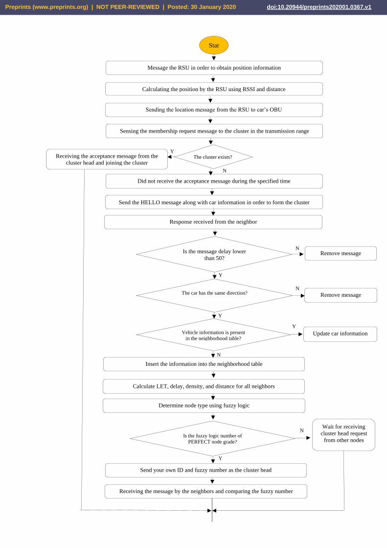
Flowchart of the operation steps of the proposed LAC-VANET method is presented in Figure XX.
Preprints (www.preprints.org) | NOT PEER-REVIEWED | Posted: 30 January 2020 doi:10.20944/preprints202001.0367.v1
Yes
Star
t
Message the RSU in order to obtain position information
Calculating the position by the RSU using RSSI and distance
Sending the location message from the RSU to car’s OBU
Sensing the membership request message to the cluster in the transmission range
Receiving the acceptance message from the
cluster head and joining the cluster
The cluster exists?
Did not receive the acceptance message during the specified time
Send the HELLO message along with car information in order to form the cluster
Response received from the neighbor
Is the message delay lower
than 50? Remove message
Calculate LET, delay, density, and distance for all neighbors
The car has the same direction?
Remove message
Insert the information into the neighborhood table
Vehicle information is present in the neighborhood table?
Update car information
Determine node type using fuzzy logic
Is the fuzzy logic number of
PERFECT node grade?
Wait for receiving
cluster head request
from other nodes
Send your own ID and fuzzy number as the cluster head
Receiving the message by the neighbors and comparing the fuzzy number
N
N
N
N
Y
es
Yes
Y
es
N
Y
Preprints (www.preprints.org) | NOT PEER-REVIEWED | Posted: 30 January 2020 doi:10.20944/preprints202001.0367.v1

FIGURE XX. FLOWCHART OF THE PROPOSED LAC-VANET METHOD
IV. EVALUATING THE PERFORMANCE
In the following section, the performance of our proposed LAC-VANET approach is evaluated to location-aware distributed clustering.
A. Performance metrics
In this section, the effectiveness and performance of our proposed LAC-VANET approach is thoroughly evaluated with comprehensive simulations. The results are compared with VMaSc approach proposed in [10-17] respectively. The average throughput, Packet
Delivery Ratio (PDR), end to end delay, and packet loss rate are evaluated.
1) Average throughput
Average throughput is the division of the sum of
packets sizes received at the destination sensor node,
to the difference of simulation stop and start time. Eq.
(7) obtains the average throughput for N experiments,
and is calculated in Kilobits per second [18].
1
*1 8
* *1000
n
i s
i
p T
X P
Throughputn S S
==−
(7)
Accept the cluster head and send your ID for admission
Sending periodic messages from cluster members to the cluster head
Received cluster head’s
fuzzy number is higher?
Do not accept the cluster head
and send your own ID and fuzzy
number as the cluster head
Send a message to the cluster head for broadcast in the network
Sending the message to the RSU by the cluster head for transmission to other
cluster heads and to all cluster members if needed
Continue data transmission procedure to the cluster head
Send a message to
members of the
cluster to restart
clustering
End
Cluster head energy is %30 of
the initial energy?
Is cluster stability> 𝑇𝐻𝐻 or cluster stability< 𝑇𝐻𝐿 ?
Not received the periodic
message from the cluster head
or cluster members?
N
Y
Y
N
N
Y
Y
N
Preprints (www.preprints.org) | NOT PEER-REVIEWED | Posted: 30 January 2020 doi:10.20944/preprints202001.0367.v1
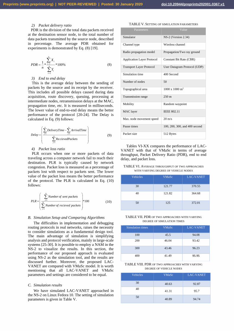
2) Packet delivery ratio
PDR is the division of the total data packets received
at the destination sensor node, to the total number of
data packets transmitted by the source node, described
in percentage. The average PDR obtained for
experiments is demonstrated by Eq. (8) [19].
1
1
1* *100%
n
i
i
n
i
i
X
PDRn
Y
=
=
=
(8)
3) End to end delay
This is the average delay between the sending of
packets by the source and its receipt by the receiver.
This includes all possible delays caused during data
acquisition, route discovery, queuing, processing at
intermediate nodes, retransmission delays at the MAC,
propagation time, etc. It is measured in milliseconds.
The lower value of end-to-end delay means the better
performance of the protocol [20-24]. The Delay is
calculated in Eq. (9) follows:
1 1
1
Re
n n
j j
n
j
DeliveryTime ArrivalTime
Delay
cievedPackets
= =
=
−
=
(9)
4) Packet loss ratio
PLR occurs when one or more packets of data
traveling across a computer network fail to reach their
destination. PLR is typically caused by network
congestion. Packet loss is measured as a percentage of
packets lost with respect to packets sent. The lower
value of the packet loss means the better performance
of the protocol. The PLR is calculated in Eq. (10)
follows:
1
1
*100
N
j
N
j
Number of sent packets
PLR
Number of recieved packets
=
=
=
(10)
B. Simulation Setup and Comparing Algorithms
The difficulties in implementation and debugging routing protocols in real networks, raises the necessity to consider simulations as a fundamental design tool. The main advantage of simulation is simplifying analysis and protocol verification, mainly in large-scale systems [25-30]. It is possible to employ a NAM in the NS-2 to visualize the results. In this section, the performance of our proposed approach is evaluated using NS-2 as the simulation tool, and the results are discussed further. Moreover, the proposed LAC-VANET are compared with VMaSc model. It is worth mentioning that all LAC-VANET and VMaSc parameters and settings are considered to be equal.
C. Simulation results
We have simulated LAC-VANET approached in the NS-2 on Linux Fedora 10. The setting of simulation parameters is given in Table V.
TABLE V. SETTING OF SIMULATION PARAMETERS
Parameters Value
Simulator NS-2 (Version 2.34)
Channel type Wireless channel
Radio propagation model Propagation/Two ray ground
Application Layer Protocol Constant Bit Rate (CBR)
Transport Layer Protocol User Datagram Protocol (UDP)
Simulation time 400 Second
Number of nodes 50
Topographical area 1000 x 1000 m2
Transmission range 250 m
Mobility Random waypoint
MAC layer IEEE 802.11
Max. node movement speed 20 m/s
Pause times 100, 200, 300, and 400 second
Packet size 512 Bytes
Tables VI-XX compares the performance of LAC-VANET with that of VMaSc in terms of average throughput, Packet Delivery Ratio (PDR), end to end delay, and packet loss.
TABLE VI. AVERAGE THROUGHPUT OF TWO APPROACHES
WITH VARYING DEGREE OF VEHICLE NODES
TABLE VII. PDR OF TWO APPROACHES WITH VARYING
DEGREE OF SIMULATION TIMES
TABLE VIII. PDR OF TWO APPROACHES WITH VARYING
DEGREE OF VEHICLE NODES
Vehicles VMaSc LAC-VANET
30 121.77 370.55
40 121.82 364.68
50 125 372.01
Simulation times VMaSc LAC-VANET
100 45.5 94.08
200 46.04 93.42
300 43.46 96.23
400 41.49 95.95
Vehicles VMaSc LAC-VANET
30 40.63 92.87
40 41.31 95.7
50 40.89 94.74
Preprints (www.preprints.org) | NOT PEER-REVIEWED | Posted: 30 January 2020 doi:10.20944/preprints202001.0367.v1

TABLE IX. DELAY OF TWO APPROACHES WITH VARYING
DEGREE OF VEHICLE NODES
TABLE X. DELAY OF TWO APPROACHES WITH VARYING
DEGREE OF SIMULATION TIMES
TABLE XX. PACKET LOSS RATE OF TWO APPROACHES WITH
VARYING DEGREE OF VEHICLE NODES
Figure XXX, demonstrates the comparison between our proposed LAC-VANET scheme, and VMaSc model in terms of throughput. Since throughput is a vital parameter in VANETs, we evaluated this parameter to evaluate our method. As shown in Figure XXX, LAC-VANET increases the throughput by more than 45% those of VMaSc model.
FIGURE XXX COMPARISON OF THE LAC-VANET
PROPOSED SCHEME AND VMASC MODEL IN TERM OF AVERAGE
THROUGHPUT.
Figure XL and L demonstrates the relationship
between PDR, number of vehicles, and Simulation
times. With 200 active vehicles, the PDR is relatively
low for the VMaSC method. The reason for this is the
fact that in such conditions, some packets fail to reach
destination in the designated timeframe. However,
since increasing the number of vehicles results in more
packets being delivered to the destination, using more
vehicles would slightly improve the PDR. As shown in
the Figure XL and L, LAC-VANET increases the PDR
by more than 43.5% those of VMaSC model.
FIGURE XL COMPARISON OF THE LAC-VANET PROPOSED
SCHEME AND VMASC MODEL IN TERM OF PDR.
FIGURE L COMPARISON OF THE LAC-VANET PROPOSED
SCHEME AND VMASC MODEL IN TERM OF PDR
Figure LX and LXX, shows end-to-end delay
against the simulation time and number of vehicles.
From the following graph, we can say that value of
end-to-end delay for VMaSC is increasing but not
constantly when we vary time of pause time from 100
to 200, end to end delay increases sharply for 300 until
400 pause time. In proposed approach at pause time
100 to 400, end-to-end delay is improved compared to
VMaSC when we vary time of pause time from 100 to
200, end to end delay decreases minor for 300 until 400
pause time.
FIGURE LX COMPARISON OF THE LAC-VANET PROPOSED
SCHEME AND VMASC MODEL IN TERM OF DELAY.
Vehicles VMaSc LAC-VANET
30 5171 945
40 5149 923
50 5253 1028
Simulation times VMaSc LAC-VANET
100 1228 331
200 2435 473
300 3739 685
400 5188 931
Vehicles VMaSc LAC-VANET
30 18.75 3.03
40 15.52 4.65
50 13.24 2.83
Preprints (www.preprints.org) | NOT PEER-REVIEWED | Posted: 30 January 2020 doi:10.20944/preprints202001.0367.v1

FIGURE LXX COMPARISON OF THE LAC-VANET
PROPOSED SCHEME AND VMASC MODEL IN TERM OF DELAY.
The number of lost packets in the network of
VANET is always high due to the existence of security
attacks. So, we also consider the number of lost packets
as a criterion to evaluate the proposed method. Figure
LXXX indicates that the proposed method reduces the
number of lost packets in different numbers of
vehicles. We try to achieve the main and major goal in
VANET networks, i.e. fast propagation of security and
urgent messages in ITS systems, using clustering and
selecting the best cluster head based on Fuzzy logic
such that the cluster head can transfer important
information such as the obstacles and accidents
detected on the road with a suitable speed and without
creating a large traffic load in the vehicle network in
order to notify other vehicles and prevent the danger
and vehicle accidents.
FIGURE LXXX COMPARISON OF THE LAC-VANET
PROPOSED SCHEME AND VMASC MODEL IN TERM OF PACKET
LOSS RATE.
V. CONCLUSIONS
In this paper, a new clustering algorithm called LAC-VANET which is based on the score values considering delay, distance, LET and density, is proposed. We try to achieve the main and major goal in VANET networks, i.e. fast propagation of security and urgent messages in ITS systems, using clustering and selecting the best cluster head based on fuzzy logic such that the cluster head can transfer important information such as the obstacles and accidents detected on the road with a suitable speed and without creating a large traffic load in the vehicle network in order to notify other vehicles and prevent the danger and vehicle accidents. In our
analysis, the performance of our proposed LAC-VANET scheme is evaluated using NS-2. The results confirmed that our scheme is capable of exhibiting high-levels of security and high average throughput (exceeding 350 kbps). It addition, our proposed scheme has high PDR (more than 95.41%), low Delay (less than 1000 sec), and low Packet loss rate (less than 4.1%), in comparison with the other approach currently being employed.
REFERENCES
1. Lakshmanaprabu, S. K., Shankar, K., Rani, S. S., Abdulhay, E., Arunkumar, N., Ramirez, G., & Uthayakumar, J. (2019). An effect of big data technology with ant colony optimization based routing in vehicular ad hoc networks: Towards smart cities. Journal of cleaner production, 217, 584-593.
2. Fotohi, R., & Jamali, S. (2014). A comprehensive study
on defence against wormhole attack methods in mobile
Ad hoc networks. International journal of Computer
Science & Network Solutions, 2, 37-56.
3. Jamali, S., & Fotohi, R. (2016). Defending against
wormhole attack in MANET using an artificial immune
system. New Review of Information Networking, 21(2),
79-100.
4. Jamali, S., Fotohi, R., Analoui, M. (2018). An Artificial
Immune System based Method for Defense against
Wormhole Attack in Mobile Adhoc Networks. TABRIZ
JOURNAL OF ELECTRICAL ENGINEERING, 47(4),
1407-1419
5. Fotohi, R. (2020). Securing of Unmanned Aerial
Systems (UAS) against security threats using human
immune system. Reliability Engineering & System
Safety, 193, 106675. 6. Yahiabadi, S. R., Barekatain, B., & Raahemifar, K.
(2019). TIHOO: An Enhanced Hybrid Routing Protocol in Vehicular Ad-hoc Networks. EURASIP Journal on Wireless Communications and Networking, 2019(1), 192.
7. Zandiyan S, Fotohi R, Koravand M. P‐method:
Improving AODV routing protocol for against network
layer attacks in mobile Ad‐Hoc networks. International
Journal of Computer Science and Information Security.
2016 Jun 1;14(6):95.
8. Jamali, S., & Fotohi, R. (2017). DAWA: Defending
against wormhole attack in MANETs by using fuzzy
logic and artificial immune system. the Journal of
Supercomputing, 73(12), 5173-5196.
9. Lodeiro-Santiago, M., Caballero-Gil, P., Aguasca-
Colomo, R., & Caballero-Gil, C. (2019). Secure UAV-
Based System to Detect Small Boats Using Neural
Networks. Complexity, 2019.
10. Fotohi, R., Heydari, R., & Jamali, S. (2016). A Hybrid
routing method for mobile ad-hoc networks. Journal of
Advances in Computer Research, 7(3), 93-103.
11. Fotohi, R., & Bari, S. F. (2020). A novel
countermeasure technique to protect WSN against
denial-of sleep attacks using firefly and Hopfield neural
network (HNN) algorithms. The Journal of
Supercomputing, 1-27. 12. Saleh, A. I., Gamel, S. A., & Abo-Al-Ez, K. M. (2017).
A reliable routing protocol for vehicular ad hoc networks. Computers & Electrical Engineering, 64, 473-495.
13. Moridi, E., & Barati, H. (2017). RMRPTS: a reliable multi-level routing protocol with tabu search in VANET. Telecommunication Systems, 65(1), 127-137.
14. Wu, C., Ohzahata, S., & Kato, T. (2013). Flexible, portable, and practicable solution for routing in
Preprints (www.preprints.org) | NOT PEER-REVIEWED | Posted: 30 January 2020 doi:10.20944/preprints202001.0367.v1

VANETs: A fuzzy constraint Q-learning approach. IEEE Transactions on Vehicular Technology, 62(9), 4251-4263.
15. Eiza, M. H., & Ni, Q. (2013). An evolving graph-based reliable routing scheme for VANETs. IEEE transactions on vehicular technology, 62(4), 1493-1504.
16. Sarkohaki, F., Fotohi, R., & Ashrafian, V. (2017). An
efficient routing protocol in mobile ad-hoc networks by
using artificial immune system. International Journal of
Advanced Computer Science and Applications
(IJACSA), 8 (4).
17. Fotohi, R., Ebazadeh, Y., & Geshlag, M. S. (2016). A
new approach for improvement security against DoS
attacks in vehicular ad-hoc network. International
Journal of Advanced Computer Science and
Applications, 7(7), 10-16.
18. Behzad, S., Fotohi, R., Balov, J. H., & Rabipour, M. J.
(2018). An Artificial Immune Based Approach for
Detection and Isolation Misbehavior Attacks in
Wireless Networks. JCP, 13(6), 705-720.
19. Mabodi, K., Yusefi, M., Zandiyan, S., Irankhah, L., &
Fotohi, R. Multi-level trust-based intelligence schema
for securing of internet of things (IoT) against security
threats using cryptographic authentication. The Journal
of Supercomputing, 1-25.
20. Fotohi, R., Jamali, S., Sarkohaki, F., & Behzad, S.
(2013). An Improvement over AODV routing protocol
by limiting visited hop count. International Journal of
Information Technology and Computer Science
(IJITCS), 5(9), 87-93
21. Xu, S., Guo, P., Xu, B., & Zhou, H. (2013). QoS evaluation of VANET routing protocols. Journal of Networks, 8(1), 132.
22. Fatemidokht, H., & Rafsanjani, M. K. (2018). F-Ant: an effective routing protocol for ant colony optimization based on fuzzy logic in vehicular ad hoc networks. Neural Computing and Applications, 29(11), 1127-1137.
23. Souza, A. B., Celestino, J., Xavier, F. A., Oliveira, F. D., Patel, A., & Latifi, M. (2013, January). Stable multicast trees based on Ant Colony optimization for vehicular Ad Hoc networks. In The International Conference on Information Networking 2013 (ICOIN) (pp. 101-106). IEEE.
24. Fotohi, R.; Nazemi, E. An Agent-Based Self-Protective
Method to Secure Communication between UAVs in
Unmanned Aerial Vehicle Networks. Preprints 2020,
2020010229 (doi: 10.20944/preprints202001.0229.v1).
25. Behzad, S., Fotohi, R., & Jamali, S. (2013).
Improvement over the OLSR routing protocol in mobile
Ad Hoc networks by eliminating the unnecessary loops.
International Journal of Information Technology and
Computer Science (IJITCS), 5(6), 2013.
26. Behzad, S., Fotohi, R., & Dadgar, F. (2015). Defense
against the attacks of the black hole, gray hole and
wormhole in MANETs based on RTT and PFT.
International Journal of Computer Science and Network
Solutions (IJCSNS), 3, 89-103.
27. Seyedi, B., & Fotohi, R. NIASHPT: a novel intelligent
agent-based strategy using hello packet table (HPT)
function for trust Internet of Things. The Journal of
Supercomputing, 1-24.
28. Fotohi, R., Bari, S. F., & Yusefi, M. (2019). Securing
Wireless Sensor Networks Against Denial‐of‐Sleep
Attacks Using RSA Cryptography Algorithm and
Interlock Protocol. International Journal of
Communication Systems. 29. Ucar, S., Ergen, S. C., & Ozkasap, O. (2013, April).
VMaSC: Vehicular multi-hop algorithm for stable clustering in vehicular ad hoc networks. In 2013 IEEE
Wireless Communications and Networking Conference (WCNC) (pp. 2381-2386). IEEE.
30. Jamali, S., & Fotohi, R. (2017). DAWA: Defending against wormhole attack in MANETs by using fuzzy logic and artificial immune system. the Journal of Supercomputing, 73(12), 5173-5196.
Preprints (www.preprints.org) | NOT PEER-REVIEWED | Posted: 30 January 2020 doi:10.20944/preprints202001.0367.v1