Exergy destruction and losses on four North Sea offshore ...
International Journal of Mechanical & Mechatronics Engineering IJMME-IJENS Vol:16 No:02 10
157306-1602-9191-IJMME-IJENS © April 2016 IJENS I J E N S
Localization of Exergy Destruction in Industrial
Thermal Oil Heater
S. S. Wahid1, M. Attalla
2, S. A. Ahmed
3, M. A. Mohamed 4 and Ahmed Ali Abd El-Rahman
5
1Dep.ofMechanical Power Engineering,MiniaUniversity,Egypt.
2,4Dep.ofMechanical Power Engineering, South Valley University, Egypt. 3
Dep.ofMechanical Power Engineering,BeniSuef University,Egypt. 4Lecturer, Department of Mechanical Engineering, Faculty of Engineering, South Valley University, Qena, 83523, Egypt.
5 The Corresponding Author
The Aluminum Company of Egypt, Qena, Egypt.
Email: [email protected], Mobile:00201000647689.
Abstract— Thermodynamic and technology parameters of
green carbon anode manufacture should be optimized in order to
decrease energy consumption. Exergy Efficiency or second law of
thermodynamics determinates the degree of sophistication of the
process. Its definition of system heat-using elements in green
carbon anode manufacture allows revealing some units defined
by considerable irreversibility. Exergy analysis allows accounting
and identifying the destruction of Exergy through the green
carbon anode plant elements.
Further than the aluminum industry has the highest Exergy
efficiency in the total aluminum plant of 52.5%. Mean ambient
environment
temperature is also proposed as a tool for understanding the
degree of quality of energy required in this industry and
consequently better quality matching which leads to better
energy quality utilization. The purpose of this study is to assess
the use of principal of availability of energy in Egyptian
industrial sector. The Exergy analysis has been performed along
with energy analysis, in order to gain deeper and more realistic
understanding of the sector’s condition. The sources of energy
degradation and the mechanisms which cause degradation
ofquality of energy have been identified. Moreover remedial
actions for better utilization of availability of energy are
proposed. Index Term--Combustion,Exergy, Energy, Green Anode, Coke,
Thermal System.
NOMENCLATURE
A Area [2 m ] S Distance [m]
AbsA The absolute availability of a system [-] oS Entropy of a system at
environmental state [J/kg]
pC , c Specific heat capacity [J/kgK] or heat
capacity [J/kg] iS Specific entropy, of substance I,
[J/kgK]
e, E Specific exergy [J/kg] or available work [J] T Temperature [K]
fE Fuel exergy [kJ/kg] u, U Specific internal energy [J/kg] or
internal energy [J]
ch
ch Ae Chemical exergy [kJ/kg] v, V Specific volume [ /kg m 3] or
volume [3 m ]
E/Q Exergy factor [no unit, %] σ Stefan-Boltzmann constant [42K W/m ]
h, H Specific enthalpy [J/kg] or enthalpy [J] Є The emissivity [-]
am Mass flow rate of air [kg/s] ώ Exergetic efficiency [-]
fm Mass flow rate of fuel [kg/s] q, Q Specific heat [J/kg] or heat [J]
oP Environment pressure [bar]
I. INTRODUCTION
The most common thermodynamic assessment parameter is
energy efficiency. It is considered an indicator how well an
energy conversion or transfer process is accomplished.
However, this definition is not sufficiently precise, as energy
efficiency does not take into account internal irreversibility.
Exergy analysis is a universal method for evaluating the
rational use of energy. It can be applied to any kind of energy
conversion system or chemical process. An exergy analysis
identifies the location, the magnitude and the causes of
thermodynamic inefficiencies and enhances understanding of
the energy conversion processes in complex systems,
moreover exergy destruction accounting give us the chance to
put our hands on the points where our available energy
destroyed and create more efficient machines and systems

International Journal of Mechanical & Mechatronics Engineering IJMME-IJENS Vol:16 No:02 11
157306-1602-9191-IJMME-IJENS © April 2016 IJENS I J E N S
which can use the energy by improved and optimized
methods.
The analysis of the real thermodynamic inefficiencies in a
system and the system components is valuable for improving
an energy-intensive operation. Exergy destruction accounting
may be used for make the systems more efficient for saving
energy, environment consideration, and less fuel consumption.
Exergy analysis allows accounting and identifying the
destruction of Exergy through the thermal oil heating plant
components. The plant is evaluated on the basis of the first
and second laws of thermodynamics, expressed by the mass,
energy and exergy balances of the system. Exergy rate of each
process stream is calculated and the exergetic balance of each
plant’s component is presented, in order to identify the amount
and the place where losses and irreversibility occur. Rational
and simple exergetic efficiency are calculated for each
component of the plant and compared.
Review of previous work
Exergy analysis is particularly valuable tools in the design and
analysis of thermal systems since they help in identifying
sources of irreversibility in the system. The second law has
been applied to analysis of internal combustion engines,
turbines, boilers, heaters, and power plants. As stated
previously, the current work aims to understand Exergy losses
during combustion regimes from the viewpoint of
implementing these strategies for more efficient combustion in
Direct Fired Heaters.
Significant work has been done with regard to applying the
second law to heaters and boilers simulations in the past.
One of the first works to include a rigorous treatment of the
chemical Exergy component in Exergy analysis of the engines
was conducted by Van Gerpen and Shapiro . Van Gerpen and
Shapiro outline the need for including the chemical Exergy
component for Exergy analysis. They also conclude that the
chemical Exergy contribution is significant and needs to be
incorporated into the calculations to obtain an accurate
estimate of the irreversibility of the processes. The work by
Van Gerpen and Shapiro showed that the chemical Exergy
increases in significance with increasing temperature and
pressure and for richer equivalence ratios. This is mainly due
to the increased concentrations of species such as carbon
monoxide and hydrogen which are not present in the
atmosphere and have a significant chemical energy associated
with them.
II. EXPERIMENTALTEST REG
Thermal fluid systems Figure1 provides an efficient means of
supplying indirect heat to one or more process systems. Such
systems offer both high temperature and low pressure, making
them ideal for a wide variety of process heating application.
The heat transfer fluid firstly heated by means of a direct fired
heater then circulated through a closed loop systems to the
users. Heat from the fluid is transferred to the user and then
re-circulated for reheating and the cycle repeated. However,
organic media has become more common and often replaces a
classic steam-water operation. The heaters are made with coils
made of seamless tubes. The thermal fluid is heated during the
flow through the tubes. The heat is transferred to the fluid as
radiant heat in the combustion chamber, where the inner
cylindrical tube coil and a flat tube coil forms the chamber
wall and the bottom respectively.
III. EXPERIMENTALBURNER
We will use the (Direct Fired Heater) which used in
EGYPTALUM company as test rig, and will describe this
heater consists here as follow:
Design of Directly Fired Heaters
Because most heat carriers decompose from a certain
temperature, this temperature must not be exceeded at any
point in the heater. A circular furnace cross-section is almost
exclusively chosen to maintain a constant ratio of flame
diameter to furnace diameter because of the axially
symmetrical flame shape. At our test rig the furnace have a
cylindrical furnace with a heating surface consisting of tubes
of constant diameter. The maximum permissible internal tube
wall temperature exists in this design only over a small range.
The life of the heat carrier depends on the maximum residence
time and the participating volume in the thermal boundary
layer, as will describe in next section. A heat carrier exposed
only partially to the maximum permissible temperature has a
longer life, Figure 1 show the construction of the Direct Fired
Heater.

International Journal of Mechanical & Mechatronics Engineering IJMME-IJENS Vol:16 No:02 12
157306-1602-9191-IJMME-IJENS © April 2016 IJENS I J E N S
EXPERIMENTALFUEL
The fuel that will be used in this test will be Natural gas. Natural
gas is a subcategory of petroleum that is a naturally occurring,
complex mixture of hydrocarbons, with a minor amount of
inorganic compounds. Table 1-1 shows composition of a typical
natural gas. It indicates that methane is a major component of
the gas mixture. The inorganic compounds nitrogen, carbon
dioxide, and hydrogen sulphide are not desirable because they
are not combustible and cause corrosion and other problems in
gas production and processing systems. Depending upon gas
composition, especially the content of inorganic compounds, the
heating value of natural gas usually varies from: 33,000 to 38,000
kj/m3. Table I
Composition of a typical natural gas:
SUPPLYING, CONDUCTING AND MONITORING THE
PRIMARY AIR
The radial fan impeller supplies and compresses the air and
conducts it, via the diffuser, to the hollow ring. The primary
air flow is about fifteen per cent of the required combustion air
flow. The pressure increase caused by the primary air fan is
monitored by a differential pressure monitor. By means of an
electromagnetic valve connected in parallel the proper
operation of the monitor can be checked.
Supplying, Conducting and Distributing the Combustion
Air
The fan unit suctions the combustion air through the air inlet
elbow unit from the ambient atmosphere and conducts it
through the air proportioning assembly and the carrying and
air guiding unit into the combustion air annulus which is
formed by the outer and inner air annulus rings. From there,
the combustion air is guided through several, axially arranged
vanes uniformly into the furnace. Part of the combustion air
passes via the ring body into the space between the shroud and
the inner air annulus ring. This air then flows past the vanes of
the axial vane ring unit, which impart a whirling motion to it,
and passes into the furnace. For monitoring the fan unit, a
pressure monitor is installed.
START UP IGNITION, DESCRIPTION OF
OPERATION AND DESIGN
The igniter operates on the principle of pressure jet oil
atomization. It is designed for firing light fuel oil of a
maximum viscosity of 17 mm2/s at 20C. The fuel oil
atomized by the nozzle is ignited by a high-voltage spark
drawn between the electrode tips Figure 2. The combustion air
is either taken from the windbox.
Compound Mole Fraction
Methane 0.8407
Ethane 0.1586
Propane 0.0220
i-Butane 0.0035
n-Butane 0.0058
Nitrogen 0.0345
Total 1.0000
Heat Transfer
Medium Feed Return
Flue Gas
4
2
12
10
9
5
11
1
6
3
7
8
Fig. 1. Direct Fired Heater ( Thermal Oil Heater )
1- Housing
2- Pipe coil
3- Cover
4- Oil burner
5-Sheathing
6- Heat insulation
7- Insulating concrete
8- Fire resistant concrete
9- Seal (cover pipe coil)
10- Seal (cover housing)
11- Flue gas ring channel
12- Observation point

International Journal of Mechanical & Mechatronics Engineering IJMME-IJENS Vol:16 No:02 13
157306-1602-9191-IJMME-IJENS © April 2016 IJENS I J E N S
Fig. 2.Schematic diagram for Ignition system.
The ignition transformer generates from the power supply
voltage the high voltage required for the formation of the
ignition spark in the igniter. The high tension lead to the
ignition electrode is firmly attached to the ignition transformer
and installed at its free end with a connection plug for the
ignition electrode. The igniter assembly comprises essentially
the igniter head, stabilizing disk and ignition electrode. For
presetting the ignition oil flow a setting screw is installed. No
special air supply system is required.
EXPERIMENTAL PROCEDURES
Measurement of excess air
One of the most critical operating parameters for attaining
good combustion is excess air. Too little air can be a source of
excessive unburned combustibles and can be a safety hazard.
Too much excess air increases stack gas losses. The total
gaseous products of combustion are referred to as wet flue gas.
Solid products or residue are excluded. The wet flue gas flow
rate is used for heat transfer calculations and design of
auxiliary equipment. The total gaseous products excluding
moisture are referred to as dry flue gas; this parameter is used
in the efficiency calculations and determination of flue gas
enthalpy. The wet flue gas is the sum of the wet gas from fuel
(fuel less ash, unburned carbon and sulfur captured),
combustion air, moisture in the combustion air, additional
moisture such as atomizing steam and, if sorbent is used,
carbon dioxide and moisture from sorbent. Dry flue gas is
determined by subtracting the summation of the moisture
terms from the wet flue gas.
Flue gas analysis
The major constituents in flue gas are CO2, O2, N2 and H2O.
Excess air is determined by measuring the O2 and CO2
contents of the flue gas. Before proceeding with measuring
techniques, consider the form of the sample. A flue gas sample
may be obtained on a wet or dry basis. When a sample is
extracted from the gas stream, the water vapor normally
condenses and the sample is considered to be on a dry basis.
The sample is usually drawn through water near ambient
temperature to ensure that it is dry. The major constituents of a
dry sample do not include the water vapor in the flue gas.
When the gas is measured with an in situ analyzer or when
precautions are taken to keep the moisture in the sample from
condensing, the sample is on a wet basis. The amount of O2 in
the flue gas is significant in defining the status of the
combustion process. Its presence always means that more
oxygen (excess air) is being introduced than is being used.
Assuming complete combustion, low values of O2 reflect
moderate excess air and normal heat losses to the stack, while
higher values of O2 mean needlessly higher stack losses.
The Testo 350S unit, which measures (CO2& H2O) and O2 on
a dry volumetric basis, remains a trusted standard for verifying
the performance of electronic equipment. The Testo 350S uses
chemicals to absorb the CO2 and O2, and the amount of each
are determined by the reduction in volume from the original
flue gas sample.
Temperature measurements
Thermal oil inlet, thermal oil outlet, ambient temperature, flue
gas temperature and outer surface temperature, all are
measured in this study for more accurate calculation.
Temperature of thermal oil inlet, thermal oil out, and flue gas
will measured by PT -100 Thermocouple.
Light oil from
storage tank
Ambient Air
Intake
220 VAC
input Spark
Plug Electrode
Flexible Hose
Transformer
220 VAC to 10000 VAC
Shut
off
Valve

International Journal of Mechanical & Mechatronics Engineering IJMME-IJENS Vol:16 No:02 14
157306-1602-9191-IJMME-IJENS © April 2016 IJENS I J E N S
Fig. 3. PT100 Thermocouple
Temperature of outer surface of heater will be measured by
using Raytek® MiniTemp device Model MT2 which use
Infrared sensor technology to measure temperature of surfaces
without contact, Figure5 photo of Raytek® MiniTemp device.
Fig. 4.Raytek® MiniTemp device Model MT2
EXPERIMENTAL PROCEDURES AND METHOD OF
CALCULATIONS
The most commonly used indicator for the efficiency of
energy conversion process is the ratio of the output of useful
energy to the total energy input. This ratio is called first law
efficiency. It is based on a quantitative accounting of energy,
which reflects recognition of the first law of thermodynamics
and the law of conservation of energy.
It is well known that the second law of thermodynamics
defines the availability of energy more restrictively than the
first law. Principally, first law is silent on the effectiveness
with which availability is concerned. Analysis in terms of the
second law of thermodynamics more closely describes the
effectiveness with which systems or processes use available
energy.
Exergy losses are calculated by making Exergy balance for
each component of the system. Unlike energy balance where
the inflow is equal to outflow (when there is no internal
energy generation or consumption), in Exergy balance due to
reasons of irreversibility, Exergy inflow is always greater than
the Exergy outflow and their difference gives the Exergy loss
or Exergy destruction. Ratio of Exergy output to Exergy input
gives the Exergetic efficiency of a system.
Tests and readout measurements for eight adjustment natural
gas flow rate, and for all natural gas flow rate adjustment, we
will execute five tests at different excess air ratio. The
summations of tests which will be run are forty tests. The
eight adjustment for natural gas flow rate are controlled by of
servomotor of burner which is responsible about adjustment
the air fuel ratio for all loads and start up conditions for
burner. For all test we will measure the following:
1- Thermal fluid inlet temperature ˚C.
2- Thermal fluid outlet temperature ˚C.
3- Flue gas temperature ˚C.
4- Ambient Air temperature ˚C.
6- Natural gas flow rate m3/hr
7- Thermal fluid flow rate m3/hr
8- Thermal fluid pressure bar.
9- Excess air %.
10- Flue gas compositions.
11- Heater outer surface temperature ˚C.
Energy Calculations (First law of thermodynamics)
In this section we will apply the first law of thermodynamics
on our system; the traditional method will be used in energy
analysis by using energy balance equations and energy
conservation principle. The tendencyof this analysis is to
obtain energy analysis of Direct Fired Heater which will be
compared after that with Exergy analysis which will obtain in
next section.
Energy Analysis Formula
The energy balance can be expressed in symbols as
which shows that an energy transfer across the system
boundary results in a change in one or more of the
macroscopic energy forms: kinetic energy, gravitational
potential energy, and internal energy.
Energy enter the control volume = Energy Out from system
In this experimental, Energy enter represented as natural gas
only, and Energy Out represented as
= Exergetic efficiency = Exergy output
(1) Exergy input
E2 - E1 = Q –W (2)
(3)
Ein= Eoil + Estack + Eloss, surface + Irriv. (4)
International Journal of Mechanical & Mechatronics Engineering IJMME-IJENS Vol:16 No:02 15
157306-1602-9191-IJMME-IJENS © April 2016 IJENS I J E N S
Qoil = m*Cp*T (5)
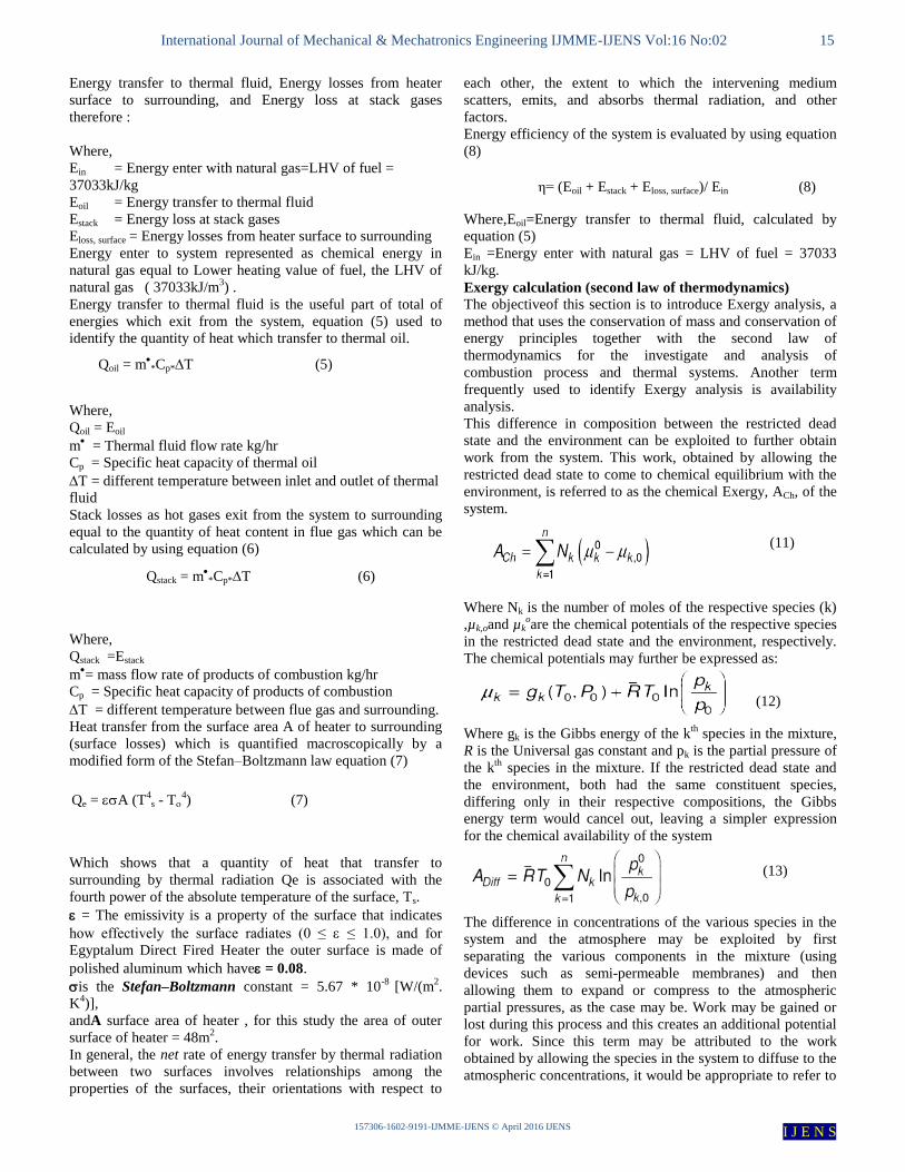
Energy transfer to thermal fluid, Energy losses from heater
surface to surrounding, and Energy loss at stack gases
therefore :
Where,
Ein = Energy enter with natural gas=LHV of fuel =
37033kJ/kg
Eoil = Energy transfer to thermal fluid
Estack = Energy loss at stack gases
Eloss, surface = Energy losses from heater surface to surrounding
Energy enter to system represented as chemical energy in
natural gas equal to Lower heating value of fuel, the LHV of
natural gas ( 37033kJ/m3) .
Energy transfer to thermal fluid is the useful part of total of
energies which exit from the system, equation (5) used to
identify the quantity of heat which transfer to thermal oil.
Where,
Qoil = Eoil
m = Thermal fluid flow rate kg/hr
Cp = Specific heat capacity of thermal oil
T = different temperature between inlet and outlet of thermal
fluid
Stack losses as hot gases exit from the system to surrounding
equal to the quantity of heat content in flue gas which can be
calculated by using equation (6)
Where,
Qstack =Estack
m= mass flow rate of products of combustion kg/hr
Cp = Specific heat capacity of products of combustion
T = different temperature between flue gas and surrounding.
Heat transfer from the surface area A of heater to surrounding
(surface losses) which is quantified macroscopically by a
modified form of the Stefan–Boltzmann law equation (7)
Which shows that a quantity of heat that transfer to
surrounding by thermal radiation Qe is associated with the
fourth power of the absolute temperature of the surface, Ts.
= The emissivity is a property of the surface that indicates
how effectively the surface radiates (0 ≤ ≤ 1.0), and for
Egyptalum Direct Fired Heater the outer surface is made of
polished aluminum which have = 0.08.
is the Stefan–Boltzmann constant = 5.67 * 10-8
[W/(m2.
K4)],
andA surface area of heater , for this study the area of outer
surface of heater = 48m2.
In general, the net rate of energy transfer by thermal radiation
between two surfaces involves relationships among the
properties of the surfaces, their orientations with respect to
each other, the extent to which the intervening medium
scatters, emits, and absorbs thermal radiation, and other
factors.
Energy efficiency of the system is evaluated by using equation
(8)
Where,Eoil=Energy transfer to thermal fluid, calculated by
equation (5)
Ein =Energy enter with natural gas = LHV of fuel = 37033
kJ/kg.
Exergy calculation (second law of thermodynamics)
The objectiveof this section is to introduce Exergy analysis, a
method that uses the conservation of mass and conservation of
energy principles together with the second law of
thermodynamics for the investigate and analysis of
combustion process and thermal systems. Another term
frequently used to identify Exergy analysis is availability
analysis.
This difference in composition between the restricted dead
state and the environment can be exploited to further obtain
work from the system. This work, obtained by allowing the
restricted dead state to come to chemical equilibrium with the
environment, is referred to as the chemical Exergy, ACh, of the
system.
Where Nk is the number of moles of the respective species (k)
,µk,oand µkoare the chemical potentials of the respective species
in the restricted dead state and the environment, respectively.
The chemical potentials may further be expressed as:
Where gk is the Gibbs energy of the k
th species in the mixture,
R is the Universal gas constant and pk is the partial pressure of
the kth
species in the mixture. If the restricted dead state and
the environment, both had the same constituent species,
differing only in their respective compositions, the Gibbs
energy term would cancel out, leaving a simpler expression
for the chemical availability of the system
The difference in concentrations of the various species in the
system and the atmosphere may be exploited by first
separating the various components in the mixture (using
devices such as semi-permeable membranes) and then
allowing them to expand or compress to the atmospheric
partial pressures, as the case may be. Work may be gained or
lost during this process and this creates an additional potential
for work. Since this term may be attributed to the work
obtained by allowing the species in the system to diffuse to the
atmospheric concentrations, it would be appropriate to refer to
Qstack = m*Cp*T (6)
Qe = A (T4s - T
4) (7)
η= (Eoil + Estack + Eloss, surface)/ Ein (8)
(11)
(12)
(13)

International Journal of Mechanical & Mechatronics Engineering IJMME-IJENS Vol:16 No:02 16
157306-1602-9191-IJMME-IJENS © April 2016 IJENS I J E N S
this as the “diffusion availability”. It may be noted that
diffusion availability of a system can be positive or negative,
depending on the concentrations of the various species in the
system.
The diffusion availability of a system is largely ignored since
its contribution is often small relative to the thermo-
mechanical availability ATMof the system. Also, it is not easy
to extract the diffusion availability component of the
availability since it would require the use of semi-permeable
membranes to extract the various species in the mixture before
allowing them to diffuse to atmospheric concentrations.
It is also evident from the expression for the diffusion
availability of a system that it depends on the composition of
the environment. The assumed composition of the atmosphere
therefore, makes a difference on the diffusion availability of
the system. The current work uses a standard wet atmospheric
composition unless otherwise stated. The availability of a
system, ATotal, incorporating the various components would
then be
The above expression for availability is valid for closed
systems. For open systems, the flow availability, ATotal,f needs
to be considered. This is defined as
Where H and H0 are enthalpies of the system and the restricted
dead state respectively.
In general, then, the availability of a system, ATotal, may be
expressed as a sum of the thermo-mechanical availability and
chemical availability.
ATotal=ATM+ACh (16)
The chemical availability term may further be split into
constituents, the reactive availability and diffusive availability
as:
ATotal=ATM+AReactive+ADiff(17)
Exergy analysis formula
The start point in the Exergy analysis is Exergy
balance for a system, Exergy balance for this
system can be symbolized as:
Where, Ein represent chemical Exergy involved in natural gas
enter to combustion chamber, also Exergy of fuel = LHV *
1.04.
that means Ein = 37033*1.04 = 38514 kJ/m3 natural gas
Eoilin equation (18) represent Exergy flow to thermal oil, and
calculated here from equation (19):
where, m = Thermal fluid mass flow rate kg/hr
Cp= average specific heat capacity kJ/(kg.k)
Tout=Thermal fluid outlet temperature Kelvin.
Tin = Thermal fluid inlet temperature Kelvin.
Estack in equation (18) represents Exergy flow to surrounding
with flue gases and calculated here from equation (20):
where
, in eq. (4-11), h and s represent the specific enthalpy
and entropy, respectively, at the inlet or exit under
consideration; h0 and s0 represent the respective values of
these properties when evaluated at the dead state. Values of h,
s, h0 and s0 are from standard tables of thermodynamics.
Where the underlined term is the thermomechanical
contribution of Exergy in combustion products ech
is the
chemical contribution evaluated as following :
Where, R__
= Universal Gas Constant = 8.314 kJ/kmol. K ,and
yiand e
iy denote, respectively, the mole fraction of component
i in the mixture of combustion products at T0, P0and in the
environment, with assumption that products of combustion
are modeled as an ideal gas mixture at all states considered.
Es.lossin equation (18) represents Exergy flow to surrounding
by radiation from the surface of heater and calculated here
from equation (22):
whereQe calculated from equation (4-7).
E Destruction in equation (18) represents Exergy Destruction
inside furnace because irreversibility and are calculated by
making Exergybalance for control volume in this study.
RESULTS AND ANALYSIS
In fig. (5) below, which represents the variation of energy
efficiency with variation of excess air at different levels of
fuel flow rate, it is obvious that energy efficiency trends to
decrease while excess air level increased. In microscopic view
for trend line, clear that high value of energy efficiency
achieved in range of 8% to 20% for excess air. For all levels
of fuel flow rate, energy efficiency values limited in range of
60% to 82% for all runs.
Exergy Efficiency
Exergy Efficiency Variation with Variation of excess air is
presented in the same figure (5) below at variation of natural
gas flow rate. From fig. (5) below, it is clear that the trend line
is the same as appear in energy efficiency representation in
(14)
(15)
Ein = Eoil + Estack + Es,loss+ E Destruction(18)
Eoil = Exergy flow to thermal oil = )lnTT
TTTcmin
out
oinoutp(
(19)
Estack = h - h0 - T0 (s-s0 ) + ech
(20)
Es.loss= (1 - [T / Tsurf])* Qe(22)
(21)

International Journal of Mechanical & Mechatronics Engineering IJMME-IJENS Vol:16 No:02 17
157306-1602-9191-IJMME-IJENS © April 2016 IJENS I J E N S
fig. (5) but change in value of exergy efficiency than energy
efficiency, since energy efficiency in range of 68% to 87%,
the exergy efficiency in range of 26% to 34% for the same
runs, and the higher value of exergy efficiency is achieved at
excess air in range of 8% to 20%.
0
10
20
30
40
50
60
70
80
90
100
0 20 40 60 80 100
Effic
incy
%
Excess Air Percent %
Energy Eff.
Exergy Eff.
Fig. 5. The Variations of energy efficiency and Exergy efficiency with variation of excess air ratio
Exergy losses through surface emission
Radiation and convection are the two modes that create
surface losses. The emission through these two modes depends
on the surface temperature, surface area, and condition of the
surface and wind velocity. In general, heaters are operated
inside a heaters room and the average wind velocity is almost
constant everywhere and it is around 1.5 m/s. The surface
area depends on the capacity of the heater but the surface
condition (the surface emissivity) is almost constant and in
average the surface emissivity is in the range of 0.08. The
percentage Exergy loss varies between 0.004% and 0.008 %.
Whereby, this achievesall possibilities to reduce the Exergy
loss through the surface emission, whereas the surface
temperature of the heater is in the range of 50°C to 70°C more
than the ambient. In the case of high losses from the surface it
is possible to bring the surface temperature closer to the
ambient. But the insulation cost will get increased while
reducing the surface temperature. Therefore, there should be a
compromise between these two factors and as a rule of thumb
it can be said that the surface temperature should be in the
range of 50°C more than the ambient.
The effect of variation of Flue Gas Temperature on
Energy efficiency with different levels of fuel flow rate:
In fig. (6) which represent the variation of energy efficiency
with variation of flue gas temperature, energy efficiency
decrease when flue gases temperature increase nearly in linear
relation as obvious in figure for natural gas variation between
134 m3/hr and 376 m3/hr as listed above. Therefore, by
implementing a proper operation and maintenance program,
the flue gas temperature can be maintained at a low level. But
the temperature reduction should be limited to 180°C.
According to this there should be an optimum limit for flue
gas parameters in Direct Fired Heaters. The equivalent O2
concentration is 1.5% - 3.0%. If the combustion is complete
the equivalent CO2 concentration is 11% - 13%.
The effect of variation of Flue Gas Temperature on Exergy
efficiency with different levels of fuel flow rate:
In fig. (6) which represent the variation of exergy efficiency
with variation of flue gas temperature, exergy efficiency
decreases when flue gases temperature increase nearly in
linear relation as obvious in figure for natural gas variation
between 136 m3/hr and 376 m3/hr. The effects of variation of
Flue Gas Temperature on Exergy efficiency with different
levels of fuel flow rate are the same as on energy efficiency
with different in the magnitude, also quality of the flue gas is a
measure of the combustion and the heat transfer. If the flue
gas temperature is high more Exergy is lost through the stack.
The variation of Energy Stack Losses with variation of
Excess air at variation of natural gas flow rate:
Fig. (7) below shows the variation of energy stack losses with
variation of excess air at different levels of fuel flow rate, in
this figure it is clear that general trend line go to high level of
energy which go to surrounding with flue gases with increase
of excess air level, but in range of 8% to 20% excess air stack
losses decrease and return to increase again with excess air.
Energy stack loss value limited by the range 13% to 32% for
all runs.

International Journal of Mechanical & Mechatronics Engineering IJMME-IJENS Vol:16 No:02 18
157306-1602-9191-IJMME-IJENS © April 2016 IJENS I J E N S
0
10
20
30
40
50
60
70
80
90
100
170 220 270 320 370 420
Effi
cin
cy %
Flue Gas Temp. ͦ C
Energy
Exergy
Fig.6.The variation of Energy efficiency and Exergy efficiency with variation of Flue Gas Temperatur
Fig. 7.The variation of Energy Stack Losses with variation of Excess air at variation of natural gas flow rate.
The variation of Exergy Stack Losses with variation of
Excess air at variation of natural gas flow rate:
Fig.(8) below shows the variation of exergy stack losses with
variation of excess air at different level of fuel flow rate, it is
obvious that the trend line of curve are the same as appear in
fig.(7) but with changes in value of exergy stack losses than
energy stack losses , since energy stack losses vary in range of
13% to 32%, while exergy stack losses vary in range 2% to
12% for the same runs. According to the measurements taken
from the stack the flue gas temperature varies between 200°C
and 450°C. The excess air level varies between 0 % and 120%.
The Exergy loss of the flue gas varies between 2 % & 12 %
and the average is 7 %. Reference to the figures given below
the Exergy loss gets increased with increase of excess air
level. That means the increase of excess air is most greatly
affected to the thermodynamics irreversibilities associated in
the flue gas.
5.9 The Relation between Exergy Stack Losses and energy
stack losses :
Variation of exergy loss with energy loss in flue gas follows a
linear relationship Fig.9 Exergy loss is always lower than the
energy loss and approximately energy loss is three times
greater than the exergy loss in terms of MJ. The following
figures illustrate the variation pattern. The approximate
variation can be given by the following formula:
Energy loss (MJ) = 2.7 x Exergy loss + 132
Percentage energy loss = 2.3 x Percentage Exergy loss + 5.2
0
5
10
15
20
25
30
35
40
45
50
0 20 40 60 80 100
Stac
k En
erg
y lo
sse
s %
Excess Air %

International Journal of Mechanical & Mechatronics Engineering IJMME-IJENS Vol:16 No:02 19
157306-1602-9191-IJMME-IJENS © April 2016 IJENS I J E N S
0
1
2
3
4
5
6
7
8
9
10
0 10 20 30 40 50 60 70 80 90
Ex
erg
y S
tack
Lo
sses
%
Excess Air %
Fig. 8.The variation of Exergy Stack Losses with variation of Excess air at variation of natural gas flow rate.
Fig. 9. Variation of exergy loss with energy loss in flue gas
Exergy Destruction
When a system undergoes an irreversible process, the entropy
always increases and anything that generates entropy always
destroys exergy. Fig. (10) below shows the variation of
exergy destruction with variation of excess air at different
level of fuel flow rate. From figure (10), appears that exergy
destruction within the system under investigation decrease
while excess air level increase for all runs, that means the
irreversibility within the system decrease with increase of
excess air levels. The Exergy of input fuel is at a higher level.
The temperature of the combustion products is in the range of
1500ºC and the energy in this mixture transfers to thermal
fluid which is in low temperature. Mainly Direct Fired Heater
is operated in range of 200 to 400ºC, and in this study the
range is 200 to 280 ºC for thermal fluid. There is a rapid
temperature reduction in this process and due to this reason
Exergy is destroyed rapidly. Apart from the temperature
variation, the irreversibility in combustion reaction also causes
Exergy destruction. Reference to the figures (11) & (12)
represented below which show the variation of Exergy
destruction with Exergy loss in flue gas we note that the
Exergy loss through the flue gas gets increase with reduce of
percentage Exergy destruction and inverse is correct. When
the flue losses are low, that means there are more Exergy
remaining in the combustion chamber to transfer to the
thermal fluid. While transferring Exergy from combustion
products to thermal fluid, Exergy gets destroyed rapidly due to
sudden temperature reduction between the two states. If the
flue gas losses are high, fewer amounts of Exergy transfers to
thermal fluid and thus the Exergy destruction is less, but the
Exergy loss at the flue gas is high. References to these there
are limitations to get the maximum Exergitec efficiency.
0
5
10
15
20
25
30
35
0 2 4 6 8 10
En
erg
y s
tack
lo
sses
%
Exergy Stack losses %

International Journal of Mechanical & Mechatronics Engineering IJMME-IJENS Vol:16 No:02 20
157306-1602-9191-IJMME-IJENS © April 2016 IJENS I J E N S
Fig. 10.variation of exergy destruction with variation of excess air at different level of fuel flow rate.
Fig. 11.Variation of exergy destruction with variation of Exergy Loss in Flue Gas at different level of fuel flow rate.
59
60
61
62
63
64
65
66
67
68
0 20 40 60 80 100
Pe
rce
nt
Exe
rgy
De
stru
ctio
n %
Percent Excess Air %
59
60
61
62
63
64
65
66
67
68
69
0 2 4 6 8 10
Pre
rsce
nt
xerg
y D
est
ruct
ion
%
Percent Exergy Loss In Flue Gas %

International Journal of Mechanical & Mechatronics Engineering IJMME-IJENS Vol:16 No:02 21
157306-1602-9191-IJMME-IJENS © April 2016 IJENS I J E N S
50
52
54
56
58
60
62
64
66
68
70
72
74
140 160 180 200 220 240 260 280 300 320 340 360 380 400
Pe
rce
nta
ge
Ex
erg
y D
est
ruct
ion
Flue Gas TemPerature
Fig. 12.The variation of Exergy Destruction with variation of flue gas Temperature.
CONCLUSION
Exergy means the real work output that can be extracted from
a given form of energy. According to this analysis the work
output of the thermal fluid is in a very low level compared to
the work input. Therefore the Exergitec efficiency is very low
comparing the energy efficiency in Direct Fired Heater. The
Exergy destruction is in the range of 12 to 60 % in Direct
Fired Heater. Figures above show Exergetic efficiency with
flue gas temperature at different excess air levels.
The Exergy loss through the flue gas is in the range of 20 to
65 % in Direct Fired Heater, and it is in the range of 0.004 to
0.008 % for surface emission. Depending on the previous
figures the average Exergetic efficiency becomes 33 % in
Direct Fired Heater. According to this analysis the minimum
possible Exergy losses in a Direct Fired Heater should be
within the following limits:-
Percentage Exergy loss through flue gas - 20 %.Percentage
Exergy loss through surface emission - 0.005 %.
With reference to these limits the percentage Exergy
destruction is 60 % and the Exergetic efficiency is 33 %. This
is the maximum possible Exergetic efficiency that can be
taken by maintaining the optimum running condition.
REFERENCES
[1] Mechanical Engineers’ Handbook: Energy and Power, Volume
John
Wiley & Sons, Inc. [2] Caton JA. A Review of Investigations Using the Second Law of
Thermodynamics to Study Internal Combustion Engines. SAE
Technical Paper Series. Society of Automotive Engineers, 2000. [3] Van Gerpen JH, Shapiro HN, Second Law Analysis of Diesel
Engine Combustion. Journal of Engineering for Gas Turbines
and Power; 112: 129-137. January 1990.
[4] Dunbar WR, Lior N. Sources of Combustion Irreversibility. Combustion Science and Technology; 103, 41-61. 1994.
[5] Richter HJ, Knoche KF. Reversibility of Combustion Processes. In: Efficiency and Costing: Second Law Analysis of Processes,
ACS Symposium series 235, 1983: 71-85.
[6] Caton JA. On the Destruction of Availability (Exergy) Due to Combustion Processes – with Specific Application to Internal
Combustion Engines. Energy; 25: 1097-1117. 2002.
[7] Lutz AE, Larson RS, Keller JO. Thermodynamic Comparison of Fuel Cells to the Carnot Cycle. International Journal of Hydrogen
Energy; 27: 1103-1111. 2002.
[8] Van Gerpen JH, Shapiro HN, Second Law Analysis of Diesel Engine Combustion. Journal of Engineering for Gas Turbines
and Power; 112: 129-137. January 1990.
[9] Daw S, Chakravarthy K, Conklin J, Graves R.Refining Understanding of Combustion Irreversibility. In: Proceedings of
the 2004 Technical Meeting of the Central States Section of the
Combustion Institute, 2004, March 21 – 23, Austin, Texas. [10] Moran MJ, Shapiro HN. Fundamentals of Engineering
Thermodynamics. Fourth edition. John Wiley and Sons Inc: New
York, 2004.Moran MJ. Availability Analysis: A Guide to Efficient Energy Use. Prentice Hall Inc: Englewood Cliffs, NJ,
1982.
[11] Cengel YA, Boles MA. Thermodynamics: An Engineering Approach. Fourth edition. McGrawHill Publications: New York,
2002.
[12] Rosen, M.A. and Dincer, I. 2001. Exergy as the Confluence of Energy, Environment and Sustainable Development. Exergy, an
International Journal 1(1), 3-13.
[13] Kotas, T.J. The Exergy Method of Thermal Plant Analysis. Essex: Butterworths, 1985.
[14] Cownden, R. et al. 2001. Exergy Analysis of a Fuel Cell Power System for Transportation Applications. Exergy, an International
Journal 1(2),112-121