LocalDirector - cisco.com · The virtual command is used to define IP address 192.168.1.99 as a...
24
Copyright © 1997 Cisco Systems, Inc. All Rights Reserved. Page 1 of 24 Reference Guide LocalDirector Overview LocalDirector is a hardware and software solution offered by Cisco Systems; it has a secure, real-time, embedded operating system that intelligently load balances TCP/IP traffic across multiple servers. Delivering very fast performance by distributing client requests across a cluster of low-cost servers, LocalDirector dramatically reduces the cost of providing large-scale Internet services, and speeds user access to those applications. The load-balancing options of Local Director provides a flexible and adaptable method for directing TCP/IP traffic. You can configure LocalDirector to maximize the number of TCP/IP connections a server farm can manage. TCP/IP traffic is directed to different servers based on service, speed, or quantity of connections. LocalDirector is a high-performance Internet appliance with over 45-Mbps throughput. It supports a combined total of 8000 virtual IP addresses and real servers. The real servers can be a collection of heterogeneous hardware platforms and operating systems. Quick setup with no network address changes reduces system administration time. Ideal for mission-critical applications, LocalDirector provides the capability to build a highly redundant and fault-tolerant server system. Servers are automatically and transparently placed in and out of service, providing fault tolerance for servers. LocalDirector itself is equipped with an optional hot-standby failover mechanism, building increased redundancy for the server system. Figure 1 shows the front of the LocalDirector appliance, and Figure 2 shows the back. Figure 1 Front View of the Cisco LocalDirector H7484 POWER RESET Power switch Reset switch Disk drive Disk eject button Power light
Transcript of LocalDirector - cisco.com · The virtual command is used to define IP address 192.168.1.99 as a...

Copyright © 1997 Cisco Systems, Inc. All Rights Reserved.Page 1 of 24
Reference Guide
LocalDirector
OverviewLocalDirector is a hardware and software solution offered by Cisco Systems; it has a secure, real-time, embedded operating system
that intelligently load balances TCP/IP traffic across multiple servers. Delivering very fast performance by distributing client
requests across a cluster of low-cost servers, LocalDirector dramatically reduces the cost of providing large-scale Internet services,
and speeds user access to those applications.
The load-balancing options of Local Director provides a flexible and adaptable method for directing TCP/IP traffic. You can
configure LocalDirector to maximize the number of TCP/IP connections a server farm can manage. TCP/IP traffic is directed to
different servers based on service, speed, or quantity of connections.
LocalDirector is a high-performance Internet appliance with over 45-Mbps throughput. It supports a combined total of 8000
virtual IP addresses and real servers. The real servers can be a collection of heterogeneous hardware platforms and operating
systems. Quick setup with no network address changes reduces system administration time.
Ideal for mission-critical applications, LocalDirector provides the capability to build a highly redundant and fault-tolerant
server system. Servers are automatically and transparently placed in and out of service, providing fault tolerance for servers.
LocalDirector itself is equipped with an optional hot-standby failover mechanism, building increased redundancy for the server
system. Figure 1 shows the front of the LocalDirector appliance, and Figure 2 shows the back.
Figure 1 Front View of the Cisco LocalDirector
H74
84
POWER
RESET
Power switch
Reset switch
Disk drive
Disk eject button
Power light
Copyright © 1997 Cisco Systems, Inc. All Rights Reserved.Page 2 of 24
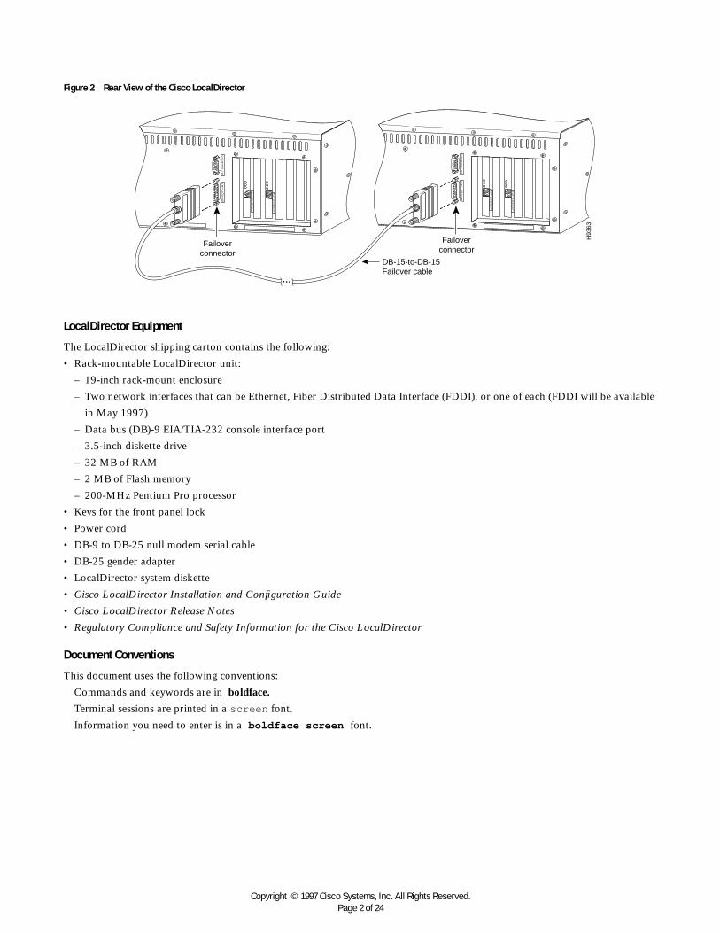
Figure 2 Rear View of the Cisco LocalDirector
LocalDirector Equipment
The LocalDirector shipping carton contains the following:
• Rack-mountable LocalDirector unit:
– 19-inch rack-mount enclosure
– Two network interfaces that can be Ethernet, Fiber Distributed Data Interface (FDDI), or one of each (FDDI will be available
in May 1997)
– Data bus (DB)-9 EIA/TIA-232 console interface port
– 3.5-inch diskette drive
– 32 MB of RAM
– 2 MB of Flash memory
– 200-MHz Pentium Pro processor
• Keys for the front panel lock
• Power cord
• DB-9 to DB-25 null modem serial cable
• DB-25 gender adapter
• LocalDirector system diskette
• Cisco LocalDirector Installation and Configuration Guide
• Cisco LocalDirector Release Notes
• Regulatory Compliance and Safety Information for the Cisco LocalDirector
Document Conventions
This document uses the following conventions:
Commands and keywords are in boldface.
Terminal sessions are printed in a screen font.
Information you need to enter is in a boldface screen font.
Failover connector
Failover connector
DB-15-to-DB-15 Failover cable
H93
63

Copyright © 1997 Cisco Systems, Inc. All Rights Reserved.Page 3 of 24
Basic ConfigurationsVirtual and Real Servers
Virtual servers present a single address for a group of real servers and load-balance service requests between the real servers in a
site. Real servers are actual host machines with unique IP addresses that provide TCP/IP services to the network. The virtual server
IP address is published to the user community, but the real IP address can remain unpublished, allowing you to hide actual site
implementation details and provide single points of contact for users.
Virtual servers and real servers can also be seen as a “TCP service” instead of just an IP address. When you define virtual and
real servers, you can specify the port traffic that will run on the server. This scenario provides the following benefits:
• You can configure application-specific server farms. In other words, with one virtual IP address and multiple virtual ports, File
Transfer Protocol (FTP) traffic can be directed to one server farm, and HyperText Transfer Protocol (HTTP) traffic can be sent
to another, allowing you to dedicate servers to specific tasks and allocate resources more efficiently.
• You can deny or accept access to a server based on service. For example, LocalDirector can deny all TCP traffic except for HTTP
traffic, providing an increased level of security.
• You can fail a service deamon instead of the server and all services running on that server. For example, multiple Web deamons
might be running on the same server, and if one of the Web deamons fails, just that deamon will fail and not the whole server.
This setup increases server farm reliability.
Basic Configuration with One Virtual Server and Multiple Real Servers
In this example, the LocalDirector is load balancing all TCP traffic over two servers to provide Web services. Figure 3 shows the
network configuration required. All traffic destined for virtual IP address 192.168.1.99 is load balanced across real servers with IP
addresses 192.168.1.1 and 192.168.1.2. Only the virtual server appears in the Domain Name System (DNS).
Figure 3 One Virtual Server and Many Real Servers
The following example shows the commands used to set up this configuration:
The enable command starts privileged mode. Then config t starts configuration mode:
LocalDirector> enable
Password:
LocalDirector# config t
The ip address command specifies LocalDirector IP address 192.168.1.89, and subnet mask 255.255.255.0:
LocalDirector(config)# ip address 192.168.1.89 255.255.255.0
The interface ethernet command with the auto option automatically determines the speed of the Ethernet interface:
LocalDirector(config)# interface ethernet 0 auto
LocalDirector(config)# interface ethernet 1 auto
Local Director Catalyst 5000Real IP
192.168.1.2 Server 1
Virtual IP 192.168.1.99
www.site.com
Real IP 192.168.1.3
Server 2

Copyright © 1997 Cisco Systems, Inc. All Rights Reserved.Page 4 of 24
The no failover command indicates that the failover option is not being used:
LocalDirector(config)# no failover
The virtual command is used to define IP address 192.168.1.99 as a virtual server, and then the name command is used to identify
192.168.1.99 as www.site.com:
LocalDirector(config)# virtual 192.168.1.99
LocalDirector(config)# name 192.168.1.99 www.site.com
The name command is used to identify IP address 192.168.1.1 as server1 and 192.168.1.2 as server2:
LocalDirector(config)# name 192.168.1.1 server1
LocalDirector(config)# name 192.168.1.2 server2
The real command is used to identify server1 and server2 as real servers:
LocalDirector(config)# real server1
LocalDirector(config)# real server2
The is (in-service) command enables the real and virtual servers to start accepting connections through the LocalDirector:
LocalDirector(config)# is real server1
LocalDirector(config)# is real server2
LocalDirector(config)# is virtual www.site.com
The bind command associates www.site.com with server1 and server2 and establishes the load-balancing relationship between the
virtual and real servers:
LocalDirector(config)# bind www.site.com server1 server2
Finally, the write mem command saves the new settings:
LocalDirector(config)# write mem
Building configuration...
[OK]
Note: The name command is optional, and can be used before or after a server is defined.
Except for failover, the default settings for LocalDirector were not changed in this example:
• No SYSLOG console is defined
• Routing Information Protocol (RIP) is not on
• Timeout is 120 minutes
• Sticky is 0
• Reassign is 3
• Threshold is 8
• Retry is 1
• Predictor is leastconns
• Weight is 1

Copyright © 1997 Cisco Systems, Inc. All Rights Reserved.Page 5 of 24
Use the write terminal command to view the running configuration before it is saved. View the saved configuration with the show
configuration command, as follows:
LocalDirector# show configuration
: Saved
: Local Director Version 1.5
syslog output 20.3
no syslog console
hostname LocalDirector
interface ethernet 0 auto
interface ethernet 1 auto
ip address 192.168.1.89 255.255.255.0
no rip passive
no failover
virtual 192.168.1.99 is
predictor 192.168.1.99 leastconns
real 192.168.1.2 is
real 192.168.1.1 is
reassign 3
weight 192.168.1.1 1
weight 192.168.1.2 1
maxconns 192.168.1.1 0
maxconns 192.168.1.2 0
name 192.168.1.1 server1
name 192.168.1.2 server2
name 192.168.1.99 www.site.com
timeout 192.168.1.1 120
timeout 192.168.1.2 120
bind 192.168.1.99 192.168.1.1
bind 192.168.1.99 192.168.1.2
sticky 192.168.1.99 0
threshold 192.168.1.2 8
threshold 192.168.1.1 8
no snmp-server contact
no snmp-server location
LocalDirector#
LocalDirector Bridging Feature
The LocalDirector has two network interfaces; one interface connects to the Internet or network, and one connects to the servers
that are load balanced by LocalDirector, which serves as a transparent learning bridge to forward data packets between its
interfaces.
Because of its bridge capability, LocalDirector must not be installed on the network parallel to another bridge. Only use
LocalDirector to connect to servers with a single way in or out to the network. If there is another path from the network to your
servers, a bridge loop is created and LocalDirector does not work properly. The LocalDirector automatically detects a bridge loop,
and SYSLOG messages are generated to indicate that there is a bridge loop.

Copyright © 1997 Cisco Systems, Inc. All Rights Reserved.Page 6 of 24
Session Distribution AlgorithmSession distribution algorithm (SDA) comprises several algorithms that allow you to distribute load between a heterogeneous cluster
of servers. The SDA harnesses the power of individual and inexpensive workstations and transforms that same cluster of servers
into a distributed computer system with the power of a supercomputer.
Server Response Curves
Figure 4 illustrates a typical response time curve for a Web server connected to the Internet via a T1 connection. Notice that for
arrival rates less than 35 (3.1 million hits per day) the response time is a mere fraction of a second. However, as the server
approaches full utilization, response time grows asymptotically toward infinity. For this Web server, the upper bound is 3.1 million
hits per day. At this point, the server is at its maximum capacity and cannot service any more requests. Web server software typically
fails at the asymptote. This response curve is similar for most servers and applications based on queuing theory (see Little’s Law).
Figure 4 Server Response Rates
Figure 5 shows how LocalDirector SDA increases the performance of a server system with two servers.
Figure 5 SDA Increases Performance
10 20 30 40 50 60 70
.065
.07
.075
.08
.085
.09
.095
Arrival (Hit) Rate (Millions)
Response Time (Seconds)
Capacity Threshold of Server
10 20 30 40 50 60 70
.065
.07
.075
.08
.085
.09
.095
Arrival (Hit) Rate (Millions)
Response Time (Seconds)
Capacity Threshold of Server
Server A+B=LocalDirector
Server B
Server A

Copyright © 1997 Cisco Systems, Inc. All Rights Reserved.Page 7 of 24
Server A and B response curves are shown individually. Also shown is the effect of SDA, when the servers are load balanced
with SDA. The response time of the server system does not increase with LocalDirector because it does not have an effect on the
CPU, memory, or input/output (I/O) of individual computers; however, the LocalDirector solution does improve the quantity and
rate of connections a server farm can service. In effect, the SDA pushes out the response curve to the right. As servers are added to
the systems, the response curve moves to the right incrementally. SDA does not increase response time; response can never be faster
than the fastest server.
Four major variables affect the shape of response curves for individual servers: bandwidth, server performance, file size, and
application performance. Less bandwidth, slower servers, and larger files shift the curve up and to the left. Different applications
respond differently and accept different quantities of connections. Ideally, the SDA analyzes your network system, determine response
curves, and automatically configure to produce the best response curve possible, given the network variables. Unfortunately, variables
involved are too diverse and random for SDA to accomplish this scenario. However, you can adjust the SDA, given your server choices,
and maximize the quantity of connections your server cluster can service.
Optimizing Server Response Curves
The predictor command options and the maxconns command allow you to optimize the response curve of the entire system:
• Least connections
• Weighted percentage
• Fastest
• Round-Robin
• Maximum connections
Least Connections
The leastconns predictor option directs the network connection to the server with the least number of open connections. Although
it may not be intuitively obvious that the leastconns predictor would provide effective load balancing, in fact, it does it quite well.
At Web sites where there is a collection of servers with similar performance, the leastconns option is effective in smoothing
distribution in situations where a server gets bogged down for any reason. In sites where there are large differences in the capacity
of various servers, the leastconns option also performs very well. In maintaining the same amount of connections to all servers,
those capable of processing (and thus terminating) connections the fastest will get more connections over time. A server deemed to
be twice as powerful as another server does, in fact, get about twice as many connections per second.
Weighted Percentage
The weighted predictor option allows you to assign a performance weight to each server. Weighted load balancing is similar to
leastconns, but servers with a higher weight value receive a larger percentage of connections at any one time. LocalDirector
administrators can assign a weight to each real server, and the LocalDirector will use this weight to determine the percentage of the
current number of connections to give each server. The default weight is one.
For example, in a configuration with five servers, the percentage of connections is calculated as follows:
Weight server1 = 7
Weight server2 = 8
Weight server3 = 2
Weight server4 = 2
Weight server5 = 5
Total weight of all servers = 24

Copyright © 1997 Cisco Systems, Inc. All Rights Reserved.Page 8 of 24
The result is that server1 will get 7/24 of the current number of connections, server2 will get 8/24, server3 will get 2/24, and
so on. If a new server, server6, is added with a weight of 10, it will get 10/34, and so on. Thus, the weighted option allows an
administrator to fine-tune LocalDirector load balancing for the Web site.
If you set the weight so that your fastest server gets 50 percent of the connections, it will get 50 percent of the connections at
that given time. Because it is faster than the other servers, it still can complete more than 50 percent of the total connections overall
because it will service the connections at a higher rate. Thus, the weight is not a fixed ratio, and it adjusts to server capacity over time.
Fastest
The fastest predictor option directs the network connection to the server with the fastest response rate, although it does not perform
consistently in varying server configurations. Web-server performance, in particular, does not follow a linear progression of response
time to number of connections. Web servers seem to respond flatly to a point, and then at a certain load there is a sharp, dramatic
increase in the response time (see Figure 4). In these situations, the fastest predictor tends to overload a particular server before
moving on to another. The fastest option works well when the server response curves are steady and do not have a sharp asymptote
as connections to the servers increase in number.
Round Robin
The roundrobin predictor option directs the network connection to the next server, and treats all servers as equals regardless of
number of connections or response time. Although the LocalDirector roundrobin predictor appears similar to DNS round robin,
there is no propagation delay or caching that would hinder the algorithm. Also, the LocalDirector can determine when a server is
not responding and avoid sending connections to that server.
Maximum Connections
Use the maxconns command to specify the maximum number of connections for each real server. By setting a limit to the maximum
connections that a server will accept, you can avoid exceeding the capacity threshold of the server as described in the section “Server
Response Curves.”
Failover and Related FunctionalityLocalDirector Failover
Failover provides a mechanism for LocalDirector to be redundant by allowing two identical units to serve the same functionality.
One LocalDirector unit is considered the “primary” unit, while the other is considered the “secondary” unit. The primary unit is
the default “active” unit, while the secondary unit is the default “standby” unit. The active unit performs its normal network
functions while the standby unit only monitors, ready to take control if the active unit fails to perform its functionality.
When a unit boots up, it defaults to Failover On and Secondary, unless “no failover” has been saved in the configuration. It
then checks to see if the failover cable is present. If the cable is not present, the unit automatically becomes the active unit. If the
cable is present, the unit that has the primary end of the failover cable plugged into it becomes the primary unit by default. The
Media Access Control (MAC) address of the primary unit is then given to the secondary unit.
The two units must be configured exactly the same and appear to the network as a single unit. They share the same IP address
and the same MAC address as well as any configuration parameters. Because the secondary unit is using the same IP and MAC
address as the primary unit, no Address Resolution Protocol (ARP) entries need to change or timeout anywhere in the network. The
MAC address used by the two units is that of the primary unit.

Copyright © 1997 Cisco Systems, Inc. All Rights Reserved.Page 9 of 24
Because each unit has the same IP address and the same MAC address, they both receive exactly the same network traffic.
Failover monitors receive network traffic counts, failover communications, and the power status of the other unit. A failure of any
of these parameters on the active unit causes the standby unit to take active control. In order for the standby unit to successfully
monitor the received traffic, it must “see” all the traffic that the active unit receives.
After a unit has entered the “failed” state, it will not assume active duty. The only way to restore a unit from the failed state is
to cycle the power. Whenever a failure or switch occurs SYSLOG messages are generated to indicate the cause of the failure.
Fault detection is based on the following:
• Received network traffic counts on incoming and outgoing network interface cards (NICs) (packet counts are kept and shared
between the units every 15 seconds); if the active unit stops receiving packets while the standby is still seeing them for two
consecutive 15-second intervals, the standby unit takes over as active
• Cable errors; the cable is wired so that each unit can distinguish between a power failure in the other unit and an unplugged cable;
if the standby unit detects that the active unit is powered off (or resets), it takes active control; if the cable is unplugged, a SYSLOG
is generated but no switching occurs
– An exception is at bootup, at which point an unplugged cable forces the unit active; if both units are powered up without the
failover cable installed, they both become active, creating a duplicate IP address conflict on your network; the failover cable
must be installed for failover to work correctly
• Failover communication; the two units share information every 15 seconds; if the standby unit doesn't hear from the active unit
in two communication attempts (a total of 30 seconds), and the cable status is OK, then the standby unit takes over as active
A switch can be initiated by either unit. When a switch occurs, each unit changes state. The newly active unit starts accepting
traffic while the new standby unit stops accepting traffic. The two units do not share connection states. Any active connections are
dropped when a failover switch occurs. The clients must re-establish the connections through the newly active unit.
Failing a Server and Adjustments
Servers are automatically taken out of service when they do not respond to packets from a requesting client. LocalDirector does not
generate additional network traffic.
Values set with the reassign and threshold commands are used to determine if a server is considered failed, and these
commands can be used to adjust how quickly a server that is not accepting connections is taken out of service. The default threshold
is eight, and the default reassign is three.
A packet from a requesting client is sent two times to a nonresponding server before it is reassigned to another server. In other
words, after the second packet receives no response from a server, the third packet is sent to another server. This value can be
adjusted with the reassign command to a number between one and four.
Each reassign process increments the threshold tally by one. When the tally reaches the threshold value, the server is considered
failed. With a default threshold value of eight, the reassign process happens eight times before the server is considered failed. To increase
how quickly servers are considered failed, reduce the threshold and reassign values. To keep a server in service longer when it is
refusing connections, increase the threshold and reassign values. Each real server can have different reassign and threshold values.
Failed Server Recovery
When a real server is failed (it does not respond to a predetermined number of connections set by the threshold command), the
following process is used to test the real machine to see if it is ready to accept more connections:
After the number of minutes set with the retry command have passed, the real machine is put into “TESTING” state. If the
show real command is used while in the testing state, TESTING is displayed in the output.
In the testing state, the machine receives one connection from a client. If the server responds, it is moved back into “IS”
(in-service) state; however, if the real machine does not respond, it is moved back to “FAILED” state and is retried.

Copyright © 1997 Cisco Systems, Inc. All Rights Reserved.Page 10 of 24
The retry command determines how quickly a server is given another packet after being failed by this process. The retry default
is 60 seconds. On the 61st second, the next packet through the LocalDirector is directed to the server to determine if it responds,
and the server is in the TESTING state. If that packet receives a response, the server is no longer in the failed state, and it is put
back in service with the reassign and threshold tallies reset to zero.
To increase how quickly a server is given a packet after being failed by LocalDirector, reduce the value of the retry command.
Hot Standby Server
To ensure that TCP services continue to run in the event that a machine is failed or out of service, you can identify an alternative destination
for server traffic by specifying a backup. The command backup is used to define a hot standby for a real or virtual server defined on the
LocalDirector. The backup can be a virtual or real machine, so it is possible to use the backup command in any combination.
For real machines, a backup is used if the real machine is failed or out of service. For a virtual machine, a backup is used if all
machines (and their backups) bound to virtual are failed or out of service. If the virtual machine itself is out of service, a reset
message is sent to the client requesting the connection.
A server cannot be used as a backup for itself. For example, a real server cannot serve as a backup for a virtual server to which
it is bound. If this configuration is attempted, an error message is displayed. When the server being backed up returns to service,
connections are no longer directed to the backup server, and they are sent according to the LocalDirector configuration.
Slowstart
If a server is brought into service under heavy network traffic, it will be bombarded with connections since it has none. The effect
of too many connections at once disables servers or seriously decreases their performance. To avoid overloading a server, an
automatic slowstart algorithm has been implemented to help bring new servers up to speed with the weighted or leastconns
predictor options. Slowstart uses the roundrobin predictor to load balance network connections until the network traffic is stable.
The show virtual command shows the predictor as “slowstart” until the number of connections on all bound real servers is within
90 percent of the desired distribution. Then the predictor switches to either weighted or leastconns, as specified in the configuration.
Slowstart is used when:
• A new real server is bound to a virtual server
• A virtual server just comes out of being failed to in service
• A real server is taken from failed or out of service to in service
• The predictor option for the virtual server was just changed
Note: Slowstart is used only with leastconns and weighted predictors.
Removing Idle Connections
The timeout command is used to determine how long idle connections are maintained before they are dropped by LocalDirector.
The default is 120 minutes, and the minimum is 15 minutes. In addition, every 2 minutes, the LocalDirector removes connections
that are not fully established (that is, either the client or server did not complete the TCP handshaking sequence to get the
connection established).

Copyright © 1997 Cisco Systems, Inc. All Rights Reserved.Page 11 of 24
Configuration ExamplesThis section provides example server configurations, including the following:
• Multiple virtual servers and one real server
• Combination of multiple virtual servers and multiple real servers
• Application-specific servers
• Load balancing across a WAN and remote hot standby server
• User Datagram Protocol (UDP)/multimedia applications
• Maximum connections and weighted configuration
• Requesting the same server for multiple connections
• Configuring for secure socket layer protocol
• Web cache configuration
Multiple Virtual Servers and One Real Server
In this example, four virtual addresses are bound to a single web server, as shown in Figure 7, allowing you to provide multiple
DNS entries with one server. In other words, one real server supports multiple domain names. Virtual IP addresses 192.168.1.99,
192.168.1.100, 192.168.1.101, and 192.168.1.102 are identified as www.pete.com, www.joe.com, www.scott.com, and
www.mary.com, respectively. Port 80 traffic for each virtual IP address is bound to different ports on real server IP 192.168.1.2.
All Web traffic destined for www.pete.com accesses information on real server 192.168.1.2 through port 8000. Traffic destined
for www.joe.com accesses information on real server 192.168.1.2 through port 8001, and so on.
Also, by defining a virtual server as an IP address and a port, you can restrict traffic to a specific port. Port 80 is specified for
each of the virtual servers, and ports 8000, 8001, 8002, and 8003 are specified for the real server. The ports on the virtual and real
servers are bound to each other directly. In addition, if the application running on port 8000 fails, the entire server is not taken out
of service by the LocalDirector solution; the remaining ports continue to accept connections.
Figure 6 Many Virtual Servers and One Real Server
A configuration example follows:
The name command is used to identify the IP addresses of the virtual and real servers:
LocalDirector(config)# name 192.168.1.99 www.pete.com
LocalDirector(config)# name 192.168.1.100 www.joe.com
LocalDirector(config)# name 192.168.1.101 www.scott.com
LocalDirector(config)# name 192.168.1.102 www.mary.com
LocalDirector(config)# name 192.168.1.2 server
www.pete.com www.joe.com www.scott.com www.mary.com
Domain Name
192.168.0.99 192.168.0.100 192.168.0.101 192.168.0.102
Virtual IP
192.168.1.2 192.168.1.2 192.168.1.2 192.168.1.2
Real IP
8000 8001 8002 8003
Port
80 80 80 80
Port

Copyright © 1997 Cisco Systems, Inc. All Rights Reserved.Page 12 of 24
The virtual command is used to identify the named IP addresses “www.pete.com,” “www.joe.com,” and “www.scott.com” as
virtual servers accepting connections on port 80. The is (in-service) option is used to indicate that the servers are in service:
LocalDirector(config)# virtual www.pete.com 80 is
LocalDirector(config)# virtual www.joe.com 80 is
LocalDirector(config)# virtual www.scott.com 80 is
LocalDirector(config)# virtual www.mary.com 80 is
The real command is used to identify the IP address named “server” as a real server that is accepting connections on ports 8000,
8001, 8002, and 8003:
LocalDirector(config)# real server 8000
LocalDirector(config)# real server 8001
LocalDirector(config)# real server 8002
LocalDirector(config)# real server 8003
The bind command is used to direct port 80 network traffic from each virtual server to a different port on the real server:
LocalDirector(config)# bind www.pete.com 80 server 8000
LocalDirector(config)# bind www.joe.com 80 server 8001
LocalDirector(config)# bind www.scott.com 80 server 8002
LocalDirector(config)# bind www.mary.com 80 server 8003
The is (in-service) command is used with the all option to indicate that all ports of the real servers are in service:
LocalDirector(config)# is real server allThe show bind command is used to view the association between the virtual and real servers:
Combination of Multiple Virtual Servers and Multiple Real Servers
You can combine multiple virtual and real servers so that each virtual server sends network traffic to virtual ports across real servers,
as shown in Figure 7. All traffic destined for virtual server 192.168.1.100 is load balanced across the three real servers on port 8001.
Traffic destined for virtual server 192.168.1.101 is load balanced across the real servers on port 8002.
A combination of virtual servers and real servers can also be used to load balance traffic across server clusters, as shown in
Figure 7.
Each virtual server can have a different load-balancing option set with the predictor command. For example, 192.168.1.100
can be configured to use the leastconns option, and 192.168.1.101 can be configured to use the weighted option.
LocalDirector(config)# show bind
Virtual Real
www.pete.com 80 (IS)
server 8000 (IS)
www.joe.com 80 (IS)
server 8001 (IS)
www.scott.com 80 (IS)
server 8002 (IS)
www.mary.com 80 (IS)
server 8003 (IS)
LocalDirector(config)#

Copyright © 1997 Cisco Systems, Inc. All Rights Reserved.Page 13 of 24
Figure 7 Multiple Virtual and Real Servers
A configuration example follows:
The virtual command is used to create two virtual servers accepting connections to port 80:
LocalDirector(config)# virtual 192.168.1.100 80
LocalDirector(config)# virtual 192.168.1.101 80
The real command is used to identify three real servers, each accepting connections on ports 8001 and 8002:
LocalDirector(config)# real 192.168.1.1 8001
LocalDirector(config)# real 192.168.1.1 8002
LocalDirector(config)# real 192.168.1.2 8001
LocalDirector(config)# real 192.168.1.2 8002
LocalDirector(config)# real 192.168.1.3 8001
LocalDirector(config)# real 192.168.1.3 8002
The bind command is used to direct network traffic from port 80 on the two virtual servers to ports 8001 and 8002 on the three
real servers:
LocalDirector(config)# bind 192.168.1.100 80 192.168.1.1 8001
LocalDirector(config)# bind 192.168.1.100 80 192.168.1.2 8001
LocalDirector(config)# bind 192.168.1.100 80 192.168.1.3 8001
LocalDirector(config)# bind 192.168.1.101 80 192.168.1.1 8002
LocalDirector(config)# bind 192.168.1.101 80 192.168.1.2 8002
LocalDirector(config)# bind 192.168.1.101 80 192.168.1.3 8002
The is (in-service) command is used to bring the real and virtual servers in service:
LocalDirector(config)# is virtual 192.168.1.100 80
LocalDirector(config)# is virtual 192.168.1.101 80
LocalDirector(config)# is real 192.168.1.1 all
LocalDirector(config)# is real 192.168.1.2 all
LocalDirector(config)# is real 192.168.1.3 all
192.168.1.100 192.168.1.101
192.168.1.1 192.168.1.1
Real IP
192.168.1.2 192.168.1.2
192.168.1.3 192.168.1.3
8001 8002
Port
8001 8002
8001 8002
Virtual IP80 80
Port
192.168.1.100 Port 80
Virtual IP
192.168.1.1 192.168.1.2 192.168.1.3
Real IP
Bind IP Address & Map Ports
8001 8001 8001
Port
192.168.1.101 Port 80
192.168.1.1 192.168.1.2 192.168.1.3
8002 8002 8002
www.pete.com
Domain Name
www.joe.com
Catalyst

Copyright © 1997 Cisco Systems, Inc. All Rights Reserved.Page 14 of 24
The show bind command is used to view the association between the virtual and real servers:
In Figure 8, TCP connections to www.pete.com are load balanced across real servers 192.168.1.1, 192.168.1.2, and
192.168.1.3. Connections to www.joe.com are load balanced across servers 192.168.1.4, 192.168.1.5, and 192.168.1.6.
Figure 8 Load Balancing across Server Clusters
LocalDirector(config) # show bind
Virtual Real
192.168.1.100 80 (IS)
192.168.1.3 8001 (IS)
192.168.1.2 8001 (IS)
192.168.1.1 8001 (IS)
192.168.1.101 80 (IS)
192.168.1.3 8002 (IS)
192.168.1.2 8002 (IS)
192.168.1.1 8002 (IS)
LocalDirector(config) #
Virtual IP 192.168.1.100192.168.1.101
Server Cluster B
Server Cluster A
Virtual IP Address 192.168.1.100 Load balances across Server Cluster A
A1 – 192.168.1.1
A2 – 192.168.1.2
A3 – 192.168.1.3
B1 – 192.168.1.4
B2 – 192.168.1.5
B3 – 192.168.1.6
Virtual IP Address 192.168.1.101 Load balances across Server Cluster B
192.168.1.100
Virtual IP Address
192.168.1.1 192.168.1.2 192.168.1.3
Real IP Address
192.168.1.101192.168.1.4 192.168.1.5 192.168.1.6
Bind IP Addresses
www.pete.com
Domain Name
www.joe.com
Catalyst

Copyright © 1997 Cisco Systems, Inc. All Rights Reserved.Page 15 of 24
A configuration example follows:
The virtual command is used to identify the two virtual servers:
LocalDirector(config)# virtual 192.168.1.100
LocalDirector(config)# virtual 192.168.1.101
The real command is used to identify the six real servers:
LocalDirector(config)# real 192.168.1.1
LocalDirector(config)# real 192.168.1.2
LocalDirector(config)# real 192.168.1.3
LocalDirector(config)# real 192.168.1.4
LocalDirector(config)# real 192.168.1.5
LocalDirector(config)# real 192.168.1.6
The bind command is used to direct network traffic from the virtual server 192.168.1.100 to real servers 192.168.1.1, 192.168.1.2,
and 192.168.1.2:
LocalDirector(config)# bind 192.168.1.100 192.168.1.1 192.168.1.2 192.168.1.3
The bind command is used to direct network traffic from the virtual server 192.168.1.101 to real servers 192.168.1.4, 192.168.1.5,
and 192.168.1.6:
LocalDirector(config)# bind 192.168.1.101 192.168.1.4 192.168.1.5 192.168.1.6
The show bind command is used to view the association between the virtual and real servers:
Application-Specific Servers
TCP services can be directed to specific servers. Figure 10 illustrates how to send HTTP traffic to servers A and B, and direct all
other traffic to servers C and D. Two virtual servers have IP address 192.168.1.100; one accepts only HTTP traffic (port 80), and
the other accepts all other connections (default).
If you do not specify a port when defining a server, the port is listed as default. A server’s default port accepts all network
connections, except for those sent to a server with the same IP address and a specific port identified.
Names can also be used to refer to the real and virtual servers in this example.
LocalDirector(config)# show bind
Virtual Real
192.168.1.100 default (OOS)
192.168.1.3 default (OOS)
192.168.1.2 default (OOS)
192.168.1.1 default (OOS)
192.168.1.101 default (OOS)
192.168.1.6 default (OOS)
192.168.1.5 default (OOS)
192.168.1.4 default (OOS)
LocalDirector(config)#

Copyright © 1997 Cisco Systems, Inc. All Rights Reserved.Page 16 of 24
Figure 9 Application-Specific Servers
A sample configuration follows:
The virtual command is used to identify two virtual servers for IP address 192.168.1.100, one accepting connections on port 80
and the other accepting default traffic:
LocalDirector(config)# virtual 192.168.1.100 80 is
LocalDirector(config)# virtual 192.168.1.100 is
The real command is used to identify two real servers accepting connections on port 80 and two real servers accepting default traffic:
LocalDirector(config)# real 192.168.1.1 80 is
LocalDirector(config)# real 192.168.1.2 80 is
LocalDirector(config)# real 192.168.1.3 is
LocalDirector(config)# real 192.168.1.4 is
The bind command is used to direct traffic for virtual server 192.168.1.100, port 80 to port 80, on real servers 192.168.1.1 and
192.168.1.2:
LocalDirector(config)# bind 192.168.1.100 80 192.168.1.1 80 192.168.1.2 80
The bind command is used to direct connections for virtual server 192.168.1.100 to real servers 192.168.1.3 and 192.168.1.4:
LocalDirector(config)# bind 192.168.1.100 192.168.1.3 192.168.1.4
The show bind command is used to view the association between the virtual and real servers:
LocalDirector(config)# show bind
Virtual Real
192.168.1.100 80 (IS)
192.168.1.2 80 (IS)
192.168.1.1 80 (IS)
192.168.1.100 default (IS)
192.168.1.4 default (IS)
192.168.1.3 default (IS)
LocalDirector(config)#
192.168.1.1
Catalyst
192.168.1.2
80
80
192.168.1.3
192.168.1.4
192.168.1.100Virtual IP
80 default
Port
Real IP Port
A
B
C
D
Servers A & B receive all web traffic
Servers C & D receive all other TCP traffic

Copyright © 1997 Cisco Systems, Inc. All Rights Reserved.Page 17 of 24
Load Balancing across a WAN and Remote Hot Standby Server
Real IP addresses do not have to be on the same LAN. Figure 11 shows a configuration with one virtual server IP address and four
real server IP addresses. One of the real server IP addresses is located in a remote site across routers and a WAN line. The
LocalDirector can load balance across all four real IP addresses.
The remote server can also be configured as a backup server for the local servers. In other words, in normal use all traffic
destined for virtual IP address 192.168.1.100 is load balanced across three real IP addresses: 192.168.1.1, 192.168.1.2 and
192.168.1.3. If one of the three servers goes out of service, the remote hot standby server starts receiving traffic to back up the failed
server. You can also set up this configuration so that all three real servers must fail before the remote server starts to receive traffic
by assigning the remote server as the backup for the virtual IP address. Use the backup command to specify the virtual or real server
to be backed up, and assign a virtual or real server as a backup.
Figure 10 Remote Server Connected by a WAN
The following configuration example shows the remote server 192.168.2.4 (remote1) configured to back up the three real servers
bound to virtual IP address 192.168.1.100:
The real command is used to identify four real servers, and the is option is used to indicate that they are in service:
LocalDirector(config)# real 192.168.1.1 is
LocalDirector(config)# real 192.168.1.2 is
LocalDirector(config)# real 192.168.1.3 is
LocalDirector(config)# real 192.168.2.4 is
The virtual command is used to identify virtual server 192.168.1.100, and the is option is used to indicate that it is in service:
LocalDirector(config)# virtual 192.168.1.100 is
The bind command is used to direct traffic for virtual server 192.168.1.100 to real servers 192.168.1.1, 192.168.1.2, and
192.168.1.3:
LocalDirector(config)# bind 192.168.1.100 192.168.1.1 192.168.1.2 192.168.1.3
The name command is used to associate names to the IP addresses of the real and virtual servers:
LocalDirector(config)# name 192.168.1.1 server1
LocalDirector(config)# name 192.168.1.2 server2
LocalDirector(config)# name 192.168.1.3 server3
LocalDirector(config)# name 192.168.2.4 remote1
LocalDirector(config)# name 192.168.1.100 www.site.com
Virtual IP204.31.33.1
Catalyst
192.168.1.2
Real IP
Remote Site
LocalDirector load balances across the remote location and the server cluster.
192.168.1.3
192.168.1.4
192.168.1.1
Real IPWAN
Copyright © 1997 Cisco Systems, Inc. All Rights Reserved.Page 18 of 24
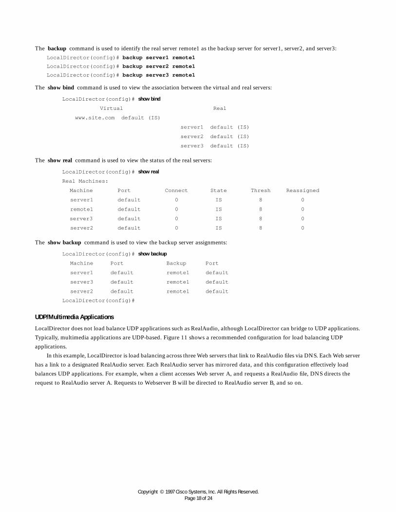
The backup command is used to identify the real server remote1 as the backup server for server1, server2, and server3:
LocalDirector(config)# backup server1 remote1
LocalDirector(config)# backup server2 remote1
LocalDirector(config)# backup server3 remote1
The show bind command is used to view the association between the virtual and real servers:
The show real command is used to view the status of the real servers:
The show backup command is used to view the backup server assignments:
UDP/Multimedia Applications
LocalDirector does not load balance UDP applications such as RealAudio, although LocalDirector can bridge to UDP applications.
Typically, multimedia applications are UDP-based. Figure 11 shows a recommended configuration for load balancing UDP
applications.
In this example, LocalDirector is load balancing across three Web servers that link to RealAudio files via DNS. Each Web server
has a link to a designated RealAudio server. Each RealAudio server has mirrored data, and this configuration effectively load
balances UDP applications. For example, when a client accesses Web server A, and requests a RealAudio file, DNS directs the
request to RealAudio server A. Requests to Webserver B will be directed to RealAudio server B, and so on.
LocalDirector(config)# show bind
Virtual Real
www.site.com default (IS)
server1 default (IS)
server2 default (IS)
server3 default (IS)
LocalDirector(config)# show real
Real Machines:
Machine Port Connect State Thresh Reassigned
server1 default 0 IS 8 0
remote1 default 0 IS 8 0
server3 default 0 IS 8 0
server2 default 0 IS 8 0
LocalDirector(config)# show backup
Machine Port Backup Port
server1 default remote1 default
server3 default remote1 default
server2 default remote1 default
LocalDirector(config)#

Copyright © 1997 Cisco Systems, Inc. All Rights Reserved.Page 19 of 24
Figure 11 UDP Recommended Configuration
Maximum Connections and Weighted Configuration
With the maxconns command, you can specify the maximum number of connections that each real server can have at one time.
A server administrator can set the maximum connections to a level that avoids exceeding the capacity threshold of the server.
Often, server administrators have a good idea of the load that a server can bear, and the maxconns command can be used to
prevent a server from failing because of capacity overload. Clients requesting connections to a server farm with no available
connections receive a timeout message.
A higher percentage of connections can be directed to servers with increased performance by selecting the weighted option of
the predictor command and setting values with the weight command.
Figure 12 shows four servers with varying performance indexes, maximum connections settings, and weight values set. In this
example, a weight of two is assigned to the Pentium 60-MHz server, which will send 13 percent of the connections to that server.
This server cannot accept more than 500 simultaneous connections, so maxconns is set to 500. The same reasoning applies to the
Pentium 166-MHz server and the two SPARCstations.
Figure 12 Maximum Connections and Weighted Performance
Web Server A
Catalyst 5000LocalDirectorCatalyst 5000
Web Server C
RealAudio Server C
RealAudio Server B
RealAudio Server A
Internet
LocalDirector Catalyst 5000
Pentium 60 MHz
Pentium 166 MHz
SPARCStation
SPARCStation
Percent of Connections
13%
20%
33%
33%
Weight
2
3
5
5
15 total
Maximum Connections
500
1000
2000
2000

Copyright © 1997 Cisco Systems, Inc. All Rights Reserved.Page 20 of 24
A sample configuration follows:
The virtual command is used to identify 192.168.1.100 as a virtual server. The is (in-service) option indicates that it is in service:
LocalDirector(config)# virtual 192.168.1.100 is
The name command is used to associate a name to the virtual server:
LocalDirector(config)# name 192.168.1.100 www.site.com
The real command is used to identify four real servers. The is (in-service) option indicates that it is in service:
LocalDirector(config)# real 192.168.1.1 is
LocalDirector(config)# real 192.168.1.2 is
LocalDirector(config)# real 192.168.1.3 is
LocalDirector(config)# real 192.168.1.4 is
The name command is used to associate names to the real servers:
LocalDirector(config)# name 192.168.1.1 pentium60
LocalDirector(config)# name 192.168.1.2 pentium166
LocalDirector(config)# name 192.168.1.3 sparc1
LocalDirector(config)# name 192.168.1.4 sparc2
The bind command is used to direct traffic for virtual server www.site.com to real servers pentium60, pentium166, sparc1, and
sparc2:
LocalDirector(config)# bind www.site.com pentium60 pentium166 sparc1 sparc2
The predictor command is used to set load balancing to the weighted option:
LocalDirector(config)# predictor www.site.com weighted
The weight command is used to assign weight values to each of the real servers:
LocalDirector(config)# weight pentium60 2
LocalDirector(config)# weight pentium166 3
LocalDirector(config)# weight sparc1 5
LocalDirector(config)# weight sparc2 5
The maxconns command is used to limit the number of connections that each real server can accept:
LocalDirector(config)# maxconns pentium60 500
LocalDirector(config)# maxconns pentium166 1000
LocalDirector(config)# maxconns sparc1 2000
LocalDirector(config)# maxconns sparc2 2000
The show real command is used to view the status of the real servers:
LocalDirector(config)# show real
Real Machines:
Machine Port Connect State Thresh Reassigned
pentium60 default 0 IS 8 0
pentium166 default 0 IS 8 0
sparc1 default 0 IS 8 0
sparc2 default 0 IS 8 0

Copyright © 1997 Cisco Systems, Inc. All Rights Reserved.Page 21 of 24
The show bind command is used to view the association between the virtual and real servers:
The show weight command is used to view the weight values assigned to the real servers:
Requesting the Same Server for Multiple Connections
The sticky command ensures that the same client gets the same server for multiple connections. This command is used when
applications require a consistent and constant connection to the same server. The sticky command allows you to get back to the
same real server again and retain the statefulness of the system. For example, if a client is completing an online form, the sticky
command ensures that multiple connections are sent to the same server in order to complete the transaction. Without this
command set, each connection attempt to a virtual server is routed according to the predictor option selected for that virtual
server, without regard to prior history of the foreign host.
The sticky command does not time how long a client is connected, it times periods of inactivity. If the sticky command is set
to five, and the client is active, new requests from the client are not sent to another server via load balancing after five minutes.
However, if five minutes of connection inactivity elapse, the requests from the client could be sent to another real server.
Configuring for Secure Socket Layer Protocol
LocalDirector supports the Secure Socket Layer (SSL) protocol; however, it is essential for the sticky command on the
LocalDirector to be set in order for an SSL transaction to occur. The sticky command enables an SSL handshake to occur
between client and server and establish an SSL session that would then allow all communication to be encrypted.
Web Cache Configuration
In this example, a large cache has been created on two servers to reduce bandwidth demands caused by international web browsing.
The system is redundant, and the LocalDirector handles load balancing between the two caches.
Both servers act as sibling caches, using the “proxy-only” option. They are connected by 100 megabit Ethernet to a core router,
one step from a border router that links to the rest of the Internet.
The two servers work together, so that if one doesn't contain the requested object, it asks its sibling for it. If neither machine
contains the requested object, the object is fetched from the Internet and cached. In other words, the proxies complement each other
with minimal overlap between their caches. This setup also allows them to act as one larger cache, providing a better overall hit rate.
LocalDirector(config)# show bind
Virtual Real
www.site.com default (IS)
sparc2 default (IS)
sparc1 default (IS)
pentium166 default (IS)
pentium60 default (IS)
LocalDirector(config)# show weight
Machine Port Weight
pentium60 default 2
pentium166 default 3
sparc1 default 5
sparc2 default 5
LocalDirector(config)#

Copyright © 1997 Cisco Systems, Inc. All Rights Reserved.Page 22 of 24
Help Information, Upgrades, and Tech SupportCisco Connection Online
Cisco Connection Online (CCO) is Cisco Systems’ primary, real-time support channel. Users can self-register on CCO to obtain
additional content and services.
Available 24 hours a day, 7 days a week, CCO provides a wealth of standard and value-added services to Cisco’s customers
and business partners. CCO services include product information, software updates, release notes, technical tips, the Bug Navigator,
configuration notes, brochures, descriptions of service offerings, and download access to public and authorized files.
CCO serves a wide variety of users through two interfaces that are updated and enhanced simultaneously—a character-based
version and a multimedia version that reside on the World Wide Web (WWW). The character-based CCO supports Zmodem,
Kermit, Xmodem, FTP, and Internet e-mail, and is excellent for quick access to information over lower bandwidths. The WWW
version of CCO provides richly formatted documents with photographs, figures, graphics, and video, as well as hyperlinks to related
information.
You can access CCO in the following ways:
• WWW: http://www.cisco.com
• WWW: http://www-europe.cisco.com
• WWW: http://www-china.cisco.com
• Telnet: cco.cisco.com
• Modem
– From North America, 408 526-8070
– From Europe, 33 1 64 46 40 82
– Use the following terminal settings: VT100 emulation; databits: 8; parity: none; stop bits: 1; and baud rates up to 28.8 kbps.
• For a copy of CCO’s Frequently Asked Questions (FAQs)
– Contact [email protected].
– For additional information, contact [email protected].
• Use CCO to obtain general information about Cisco Systems, Cisco products, or upgrades. If CCO is not accessible, contact
800 553-6387, 408 526-7208, or [email protected].
• If you are a network administrator and need personal technical assistance with a Cisco product that is under warranty or covered
by a maintenance contract, contact Cisco’s Technical Assistance Center (TAC) at 800 553-2447, 408 526-7209, or
CD-ROM Documentation
Cisco documentation and additional literature are available in a CD-ROM package, which ships with the LocalDirector product.
The Documentation CD-ROM, a member of the Cisco Connection Family, is updated monthly. Therefore, it might be more
up-to-date than printed documentation. To order additional copies of the Documentation CD-ROM, contact your local sales
representative or call Customer Service. The CD-ROM package is available as a single package or as an annual subscription. You
can also access Cisco documentation on the World Wide Web at http://www.cisco.com, http://www-china.cisco.com, or http://
www-europe.cisco.com.

Copyright © 1997 Cisco Systems, Inc. All Rights Reserved.Page 23 of 24
Technical Assistance
Technical support is available for issues regarding your LocalDirector configuration. Contact Cisco’s TAC and have the following
items ready before you call:
• A diagram of your network including IP addresses and subnet masks
• A copy of the following output from your LocalDirector:
– show real
– show virtual
– show name
– show bind
– show configuration
– show version
– show interface
– show syslog
LocalDirector Software Installation and Upgrade
LocalDirector ships with its software already in Flash RAM, and LocalDirector can boot without a system diskette. To upgrade the
LocalDirector software, insert a diskette with the new version of software on it and enter the reload command, or reboot the
LocalDirector. The existing configuration will run on the new software version.
A backup copy of your configuration should be saved to diskette with the write floppy command before upgrading to a new version
of software. Although LocalDirector will load the existing configuration from Flash memory when rebooted, it is recommended
that you keep a backup copy before upgrading or changing your configuration.
If you upgrade from Version 1.2.5 to Version 1.5, your configuration will be upgraded to run in the new version. However, if you reload
Version 1.2.5, the configuration in RAM will be lost and you must boot from your backup diskette to restore the previous configuration.
If you purchased a SMARTnet™ agreement for LocalDirector, you can register on CCO to obtain software upgrades for
LocalDirector.
At the CCO home page, log in and follow the following links:
• Service & Support
• Software
• Cisco Software Images
• Cisco LocalDirector (in the Internet Products section)
You will see a screen similar to the following:
Cisco LocalDirector
Select the file to download:
File Description
ldxxx.EXE NetBU LocalDirector disk file
ldxxx.bin NetBU LocalDirector disk file
ldxxx.txt Readme for NetBU LocalDirector disk file
rawrite.exe NetBU LocalDirector disk file

Copyright © 1997 Cisco Systems, Inc. All Rights Reserved.Page 24 of 24
Corporate HeadquartersCisco Systems, Inc.170 West Tasman DriveSan Jose, CA 95134-1706USAWorld Wide Web URL:http://www.cisco.comTel: 408 526-4000
800 553-NETS (6387)Fax: 408 526-4100
European HeadquartersCisco Systems Europe s.a.r.l.Parc Evolic-Batiment L1/L216, Avenue du QuebecBP 706-Villebon91961 Courtaboeuf CedexFranceTel: 33 1 6918 61 00Fax: 33 1 6928 83 26
Copyright © 1997 Cisco Systems, Inc. All rights reserved. Printed in USA. Catalyst, Cisco Systems, and SMARTnet are trademarks; Cisco, and the Cisco Systems logo are registered trademarks of Cisco Systems,Inc. All other trademarks, service marks, registered trademarks, or registered service marks mentioned in this document are the property of their respective owners. 7/97 B&W
Cisco Systems has more than 190 offices in the following countries. Addresses, phone numbers, and fax numbers are listed on the
C i s c o C o n n e c t i o n O n l i n e W e b s i t e a t h t t p : / / w w w . c i s c o . c o m .
Argentina • Australia • Austria • Belgium • Brazil • Canada • Chile • China (PRC) • Colombia • Costa Rica • Czech Republic • DenmarkFinland • France • Germany • Hong Kong • Hungary • India • Indonesia • Ireland • Israel • Italy • Japan • Korea • Malaysia • MexicoThe Netherlands • New Zealand • Norway • Philippines • Poland • Portugal • Russia • Singapore • South Africa • Spain • Sweden
Switzerland • Taiwan, ROC • Thailand • United Arab Emirates • United Kingdom • Venezuela
AmericasHeadquartersCisco Systems, Inc.170 West Tasman DriveSan Jose, CA 95134-1706USATel: 408 526-7660Fax: 408 526-4646
Asia HeadquartersNihon Cisco Systems K.K.Fuji Building3-2-3 MarunouchiChiyoda-ku, Tokyo 100JapanTel: 81 3 5219 6000Fax: 81 3 5219 6010
ldxxx.exe is a self-extracting file for MS-DOS or Windows that includes the binary, readme, and rawrite files.
ldxxx.bin is a binary file for the LocalDirector software.
ldxxx.txt is a readme file that includes directions for creating a LocalDirector bootable diskette.
rawrite.exe is a utility for MS-DOS or Windows that formats the ldxxx.bin file for LocalDirector use and copies the file to diskette.
To create a bootable LocalDirector diskette, perform the following steps:
If You Are Using UNIX
Download the ldxxx.bin file to your local directory.
Insert a diskette into the workstation drive, and run the following command:
dd bs=18b if=./ldxxx.bin of=/dev/rfd0
Put the diskette into the LocalDirector 3.5-in. drive. The LocalDirector runs the new version of the software once rebooted, and
will use the configuration saved in Flash memory.
If You Are Using a PC
Download the self-extracting ldxxx.exe file to your local hard drive.
Run rawrite from a DOS command prompt. When prompted, enter ldxxx.bin as the filename, and your diskette drive as the
destination drive. You will see prompts similar to the following:
C:\LDSoftware> rawrite
RaWrite 1.2 - Write disk file to raw floppy diskette
Enter source file name: ldxxx.bin
Enter destination drive: a:
Please insert a formatted diskette into drive A: and press -ENTER- :
Number of sectors per track for this disk is 18
Writing image to drive A:. Press ^C to abort.
Track: 16 Head: 1 Sector: 16
Done.
Put the diskette into the LocalDirector 3.5-in. drive. The LocalDirector runs the new version of the software once rebooted, and
will use the configuration saved in Flash memory.