Aalborg Universitet Local Exhaust Ventilation a numerical ...

Local Exhaust and Whole House Ventilation Strategies Armin Rudd
February 2011
Prepared by Building Science Corporation For the U.S. Department of Energy Building Technologies Program

i
NOTICE
This report was prepared as an account of work sponsored by an agency of the United States government. Neither the United States government nor any agency thereof, nor any of their employees, makes any warranty, express or implied, or assumes any legal liability or responsibility for the accuracy, completeness, or usefulness of any information, apparatus, product, or process disclosed, or represents that its use would not infringe privately owned rights. Reference herein to any specific commercial product, process, or service by trade name, trademark, manufacturer, or otherwise does not necessarily constitute or imply its endorsement, recommendation, or favoring by the United States government or any agency thereof. The views and opinions of authors expressed herein do not necessarily state or reflect those of the United States government or any agency thereof.
Available electronically at http://www.osti.gov/bridge
Available for a processing fee to U.S. Department of Energy and its contractors, in paper, from:
U.S. Department of Energy Office of Scientific and Technical Information
P.O. Box 62 Oak Ridge, TN 37831-0062
phone: 865.576.8401 fax: 865.576.5728
email: mailto:[email protected]
Available for sale to the public, in paper, from: U.S. Department of Commerce
National Technical Information Service 5285 Port Royal Road Springfield, VA 22161 phone: 800.553.6847
fax: 703.605.6900 email: [email protected]
online ordering: http://www.ntis.gov/ordering.htm
Printed on paper containing at least 50% wastepaper, including 20% postconsumer waste

ii
Deliverable 4.D.2 Guidelines for Measures and Strategies:
Whole House Ventilation Strategies
Prepared for:
Building America
Building Technologies Program
Office of Energy Efficiency and Renewable Energy
U.S. Department of Energy
Prepared by:
Building Science Corporation Industry Team
30 Forest Street
Somerville, MA 02143
February 10, 2011

iii
[This page left blank]

iv
Contents
List of Figures ............................................................................................................................................. v List of Tables .............................................................................................................................................. vi Definitions .................................................................................................................................................. vii Executive Summary ..................................................................................................................................... i 1 Home and/or Document Inspection .................................................................................................... 1 2 Tradeoffs ............................................................................................................................................... 2
2.1 System Interaction ........................................................................................................................... 2 2.2 Cost and Performance Tradeoffs ..................................................................................................... 3
3 Strategy Implementation Details ......................................................................................................... 6 3.1 Local Exhaust ................................................................................................................................... 6 3.2 Whole House Ventilation .................................................................................................................. 9
3.2.1 Combined Infiltration And Mechanical Ventilation Air Change Effects ............................. 10 3.2.2 Use Of Windows ............................................................................................................... 11
3.3 Supply Type Whole House Ventilation Systems ............................................................................ 11 3.3.1 Central Fan Integrated Supply .......................................................................................... 12 3.3.2 Separate Supply Fan And Duct System ........................................................................... 16
3.4 Exhaust Type Whole House Ventilation ......................................................................................... 18 3.4.1 Fan with One Room Inlet .................................................................................................. 18 3.4.2 Fan with Multiple Room Inlets ........................................................................................... 19
3.5 Supply and Exhaust Combinations ................................................................................................ 21 3.6 Balanced Type Whole House Ventilation ....................................................................................... 21
3.6.1 Heat Recovery (HRV) Or Energy Recovery (ERV) Systems ............................................ 22 4 Retrofit Measures ............................................................................................................................... 29 5 Field Inspection .................................................................................................................................. 29 6 Install Procedure................................................................................................................................. 29 7 Verification procedures and tests..................................................................................................... 29 References ................................................................................................................................................. 31 Appendix A: Pre-retrofit and Post-installation Ventilation Inspection Checklist ............................... 33

v
List of Figures
Figure 1. Schematic overview of typical ventilation equipment ........................................................... 2Figure 2. Terminating a local exhaust duct in the attic is not acceptable ........................................... 7Figure 3. Duct sealing and smooth bends make for a good local exhaust installation ..................... 8Figure 4. Sharp duct bends dramatically reduce airflow, and cloth-backed duct tape does not hold
for the long-term ................................................................................................................................... 8Figure 5. Route exhaust ducts to avoid destruction of the ducts by others ....................................... 9Figure 6. Keep exhaust outlets ................................................................................................................. 9Figure 7. Central-fan-integrated supply ventilation with air handler unit in interior mechanical
closet or basement ............................................................................................................................. 14Figure 8. Central-fan-integrated supply ventilation with air handler unit in IRC R804.6 Unvented
Attic Assembly .................................................................................................................................... 14Figure 9. Central-fan-integrated supply ventilation with small amount of supply air to conditioned
crawlspace .......................................................................................................................................... 15Figure 10. Central-fan-integrated supply ventilation with stand-alone dehumidifier in conditioned
crawlspace .......................................................................................................................................... 15Figure 11. Central-fan-integrated supply ventilation, with dehumidifier coupled to central system
supply, in conditioned crawlspace ................................................................................................... 16Figure 12. Multi-point supply ventilation to the common areas and drawing tempering air from the
bedrooms ............................................................................................................................................ 17Figure 13. Multi-point supply ventilation to the bedrooms and drawing tempering air from the
common area ..................................................................................................................................... 17Figure 14. Single-point exhaust ventilation ........................................................................................... 19Figure 15. Multi-point exhaust ventilation from all bathrooms and toilet rooms .............................. 20Figure 16. Multi-point exhaust ventilation from all bedrooms and common area ............................ 20Figure 17. Central-fan-integrated supply ventilation with single- or multi-point exhaust from
bathrooms, for balanced, intermittently balanced, or alternating unbalanced whole-house ventilation ............................................................................................................................................ 21
Figure 18. Balanced HRV/ERV, exhausting from the master bedroom and supplying to the common area ...................................................................................................................................... 23
Figure 19. Balanced HRV/ERV, exhausting from the bathrooms and supplying to the common areas .................................................................................................................................................... 24
Figure 20. Balanced HRV/ERV, exhausting from the common areas and supplying to the bedrooms ............................................................................................................................................ 24
Figure 21. Balanced HRV/ERV, exhausting from the bedrooms and supplying to the common areas .................................................................................................................................................... 25
Figure 22. Balanced HRV/ERV, exhausting from the bathrooms and supplying to the bedrooms . 25Figure 23. Partially interconnected balanced HRV/ERV, exhausting from the common areas and
supplying to the central system supply trunk ................................................................................. 26Figure 24. Partially interconnected balanced HRV/ERV, exhausting from the bathrooms and
supplying to the central system supply trunk ................................................................................. 27Figure 25. Interconnected balanced HRV/ERV, exhausting from the central return and supplying
to the central supply trunk ................................................................................................................ 27Figure 26. Interconnected balanced HRV/ERV, exhausting from the central return and supplying
at least 3 feet downstream in the central return .............................................................................. 28

vi
List of Tables
Table 1. Summary of whole-house ventilation system types and cost and performance trade-offs 4 Table 2. Local exhaust airflow requirements .......................................................................................... 7 Table 3. Furnace manufacturers’ minimum return air temperature requirements ............................ 13

vii
Definitions
ASHRAE American Society of Heating, Refrigerating and Air-Conditioning Engineers
ASTM American Society for Testing And Materials
ICC International Code Council
IRC International Residential Code
OSHA Occupational Safety and Health Administration
Pa Pascal; SI unit of pressure (equivalent to one newton per square meter)
US DOE United States Department of Energy
US EPA United States Environmental Protection Agency
Acceptable indoor air quality: Air toward which a substantial majority of occupants express no dissatisfaction with respect to odor and sensory irritation and in which there are not likely to be contaminants at concentrations that are known to pose a health risk.
Air Leakage: Uncontrolled and/or unintended airflow through a building enclosure or between units of occupancy. Leakage from indoors to outdoors is known as exfiltration and leakage from outdoors to indoors is known as infiltration. Air leakage can cause indoor air quality problems, condensation, excess energy use, comfort complaints, and smoke transport.
Basement: That portion of a building that is partly or completely below grade (see “Story above grade”) (ICC 2009)
Bathroom: Any room containing a toilet, shower, bathtub, or spa (or similar source of moisture).
Below Grade: The portion of a building that is below the line of the surrounding ground level.
Building Enclosure: The system or assembly of components that provides environmental separation between the conditioned space and the exterior environment. Note: The enclosure is a special type of environmental separator. Environmental separators also exist within buildings as dividers between spaces with different environmental conditions.
Condensation: The change of state from vapor to liquid. A common factor in moisture damage. Occurs on surfaces, which must be cooler than the air containing vapor next to it. Vapor supply to the condensation surface is usually by airflow but can be by diffusion.

viii
Kitchen: Any room where cooking of food is done.
Mold: A type of fungus that is different from plants, animals and bacteria. Molds are decomposers of dead organic material such as leaves, wood and plants. Molds sometimes can infect living plants and animals. The spores and hair-like bodies of individual mold colonies are too small for us to see without a microscope. When a lot of mold is growing on a surface, it often appears black or green. The color of mold is influenced by the nutrient source and the age of the colony. Mold growing on fabric is called mildew.
Penetration: A hole passing through the building envelope in which ducts, pipes, wires, structural elements, and windows are run between inside and outside. Windows are also a penetration.
Rigid Insulation: Rigid board material that provides thermal resistance. Foam plastic such as EPS, XPS, and polyisocyanurate are commonly used.
Vapor Barrier: A material that has a permeance of 0.1 perm or less. A vapor barrier is a material that is essentially vapor impermeable. A vapor barrier is a Class I vapor control layer. The test procedure for classifying vapor barriers is ASTM E-96 Test Method A—the desiccant or dry cup method.
Vapor Control Layer (or Layers): The component (or components) that is (or are) designed and installed in an assembly to control the movement of water by vapor diffusion. A Class I vapor control layer has permeance of less than or equal to 0.1 perm. A Class II vapor control layer has permeance of greater than 0.1 perm and less than or equal to 1.0 perm. A Class II vapor control layer has permeance of greater than 1.0 perm and less than or equal to 10.0 perm. A Class IV vapor control layer has permeance greater than 10.0 perm.
Vapor Impermeable: Materials with a permeance of 0.1 perm or less (rubber membranes, polyethylene film, glass, aluminum foil). A Class I vapor control layer.
Vapor Permeable: Materials with a permeance of greater than 10 perms (housewraps, building papers). A Class IV vapor control layer.

i
Executive Summary
Bathrooms, kitchens, and laundry rooms are places where pollutants are generated in high concentration. When these areas are being used, an exhaust fan should be active to exhaust pollutants directly to the outdoors before they can negatively impact air quality elsewhere in the home. Typically, this is done with individual, surface-mounted, bathroom exhaust fans and a kitchen range hood. Builders should purposefully educate homebuyers, explaining that their participation in any truly successful indoor air quality strategy certainly includes operation of bathroom and kitchen exhaust when those spaces are being used.
After local exhaust is applied to remove concentrated pollutants at their source, such as in bathrooms and kitchens, one must deal with the general body of pollutants (usually at a much lower concentration) that are distributed throughout a home. Since these pollutants are dispersed, there is no practical way to capture and exhaust them as typical in a toilet room, over a shower, or over a kitchen cook-top. Rather, dilution through delivery and distribution of outside is used to level and reduce the concentration of dispersed pollutants inside the home. Whole house ventilation is accomplished where fresher outside air is distributed in a controlled manner to dilute more polluted inside air. Whole house ventilation can be balanced or unbalanced, and can be operated continuously at a lower rate, or intermittently at a higher rate.
Each dwelling in the Building America program shall have controlled mechanical ventilation installed for both local exhaust and whole house ventilation without regard to the final airtightness of the building enclosure. The local exhaust and whole-building ventilation systems installed shall have sufficient airflow capacity and features to meet or exceed the requirements of ASHRAE Standard 62.2-2010. Before retrofit, a home should be inspected to document the existence and operation of any installed local exhaust and whole house ventilation equipment. A pre-retrofit documentation form is shown in Appendix A. Completion of this form will provide the designer with a full view of the existing ventilation equipment and of the challenges to overcome in providing controlled mechanical ventilation in the dwelling.
Successfully executing strategies to implement controlled mechanical ventilation is critical for occupant health, safety, and comfort as well as building durability. When provided according to the measures described in this document occupants can have effective, controlled mechanical ventilation in high performance homes for less than $0.50 per day, varying less than 50% of that regardless of climate zone or whole house ventilation system type (Rudd and Walker 2007). Clearly, it will always consume more energy to provide proper indoor air quality ventilation than to not provide it, but not providing proper indoor air quality is an unacceptable risk. Failure to provide mechanical ventilation in high performance dwellings by way of both local exhaust and whole house ventilation will result in homeowner indoor air quality complaints, builder callbacks, and potential building enclosure durability issues, all of which would result in significant financial liabilities.
Local Exhaust and Whole House Ventilation implementation strategies are described in detail. Supply, exhaust, balanced ventilation, and combinations of those systems are graphically illustrated along with important guidance commentary.

1
1 Home and/or Document Inspection
As part of the overall building design, give careful attention to the following areas to lower major sources of indoor air contaminants:
• Use sealed combustion heating appliances if located inside conditioned space.
• Provide an airtight separation between attached garages and living spaces.
• Employ water management to assure dry basements, crawlspaces, roofs and walls.
• Use pesticides and cleaning agents wisely and store them safely.
• Choose building materials, finishes, and furnishings that are known to reduce pollutant emissions.
Bathrooms, kitchens, and laundry rooms are places where pollutants are generated in high concentration. When these areas are being used, an exhaust fan should be active to exhaust pollutants directly to the outdoors before they can negatively impact air quality elsewhere in the home. Typically, this is done with individual, surface-mounted, bathroom exhaust fans and a kitchen range hood. However, it can also be done with a remotely mounted fan or heat recovery ventilator pulling from multiple locations at once. Occupancy sensors, humidity sensors, and light switch interlocks have all been used to try to influence the appropriate operation of local exhaust, but homeowner education remains the most useful tool. Builders should purposefully educate homebuyers, explaining that their participation in any truly successful indoor air quality strategy certainly includes operation of bathroom and kitchen exhaust when those spaces are being used. Especially in bathrooms, available time delay controllers which keep the exhaust fan energized for a time after the room is vacated are beneficial. Kitchen exhaust should always be active while the range or oven appliance is operating because they spill all of the combustion pollutants into the indoor environment. Also, assure that clothes dryer exhaust ducting is not restricted and that the air goes directly to outdoors.
After local exhaust is applied to remove concentrated pollutants at their source, such as in bathrooms and kitchens, one must deal with the general body of pollutants (usually at a much lower concentration) that are distributed throughout a home. Since these pollutants are dispersed, there is no practical way to capture and exhaust them as typical in a toilet room, over a shower, or over a kitchen cook-top. Rather, dilution through delivery and distribution of outside is used to level and reduce the concentration of dispersed pollutants inside the home. Whole house ventilation is accomplished where fresher outside air is distributed in a controlled manner to dilute more polluted inside air. Whole house ventilation can be balanced or unbalanced, and can be operated continuously at a lower rate, or intermittently at a higher rate.
Each dwelling in the Building America program shall have controlled mechanical ventilation installed for both local exhaust and whole house ventilation without regard to the final airtightness of the building enclosure. Figure 1 schematically illustrates a general overview of ventilation equipment combinations. Before retrofit, a home should be inspected to document the existence and operation of any installed local exhaust and whole house ventilation equipment.

2
The inspection should include a review of any documents that exist that may show details of how the HVAC system was designed and installed. A pre-retrofit documentation form is shown in Appendix A. Completion of this form will provide the designer with a full view of the existing ventilation equipment and of the challenges to overcome in providing controlled mechanical ventilation in the dwelling.
Figure 1. Schematic overview of typical ventilation equipment
2 Tradeoffs
2.1 System Interaction Mechanical ventilation causes increased air exchange between indoors and outdoors, so, naturally, there is an effect on heating and cooling loads. For example, at design conditions in

3
hot-humid climates, every 50 cfm of exhaust, supply, or balanced ventilation adds about one quarter ton of total cooling load or about 1000 W. For hot-dry climates, it is about one half of that. In cold climates, 50 cfm of ventilation adds about 1000 W of heating load. While residential ventilation loads are not large in an absolute sense, they are significant in a relative sense for low energy homes—in the range of 10-20 percent of cooling load and about 10% of heating load.
Wind and stack induced pressures usually work against venting of combustion appliances in homes. Mechanically induced pressures within homes, due to mechanical ventilation or central air distribution system duct leakage, can either work with or against venting of combustion appliances. For that reason, it is always best to use sealed combustion space heating and water heating appliances in low energy homes, and to locate all heating and cooling ductwork inside conditioned space.
In hot-humid climates, where a home with a Class I or Class II vapor control layer as an interior finish is depressurized with exhaust ventilation, or in very cold climates where a home without exterior rigid insulation is pressurized with supply ventilation, building enclosure condensation and durability issues can arise. These situations can easily be avoided with proper design such that supply or exhaust ventilation can be used throughout the United States. Balanced ventilation principally has no impact on building pressure and can be used anywhere.
2.2 Cost and Performance Tradeoffs Successfully executing strategies to implement controlled mechanical ventilation is critical for occupant health, safety, and comfort as well as building durability. When provided according to the measures described in this document occupants can have effective, controlled mechanical ventilation in high performance homes for less than $0.50 per day, varying less than 50% of that regardless of climate zone or whole house ventilation system type (Rudd and Walker 2007). Clearly, it will always consume more energy to provide proper indoor air quality ventilation than to not provide it, but not providing proper indoor air quality is an unacceptable risk. Failure to provide mechanical ventilation in high performance dwellings by way of both local exhaust and whole house ventilation will result in homeowner indoor air quality complaints, builder callbacks, and potential building enclosure durability issues, all of which would result in significant financial liabilities.

4
Table 1. Summary of whole-house ventilation system types and cost and performance trade-offs
Balanced Systems Exhaust Systems Supply Systems Exhaust and supply fans
running simultaneously Can be integrated with
heat/cool system ducts and air handler (ECM air handlers help save energy)
Use timers or other controls to empower continuous and intermittent use
Use continuous operation or use timers or other controls to empower intermittent use
Use quiet fans o 1.0 sones for continuous o 3.0 sones for intermittent
Use a fresh air duct into central air handler return duct, or use a separate supply fan with recirculation air for tempering
Use a fan timer and damper control
Combined with low airflow resistance, ECM air handlers help save energy
Advantages: o HRV or ERV technology
can recover up to 70% of heat and moisture
o Most effective regardless of house airtightness
o Applicable in all climate zones
o Known source of ventilation air
o Have opportunity to filter and temper fresh air
o Can eliminate need for other Local Exhaust fans
o Does not affect combustion appliance venting
Advantages: o Simple and inexpensive o Good for removal of
pollutants at their source o Good, quiet Local Exhaust
can double for Whole-House Ventilation
o Negative pressure can help keep walls drier in cold climates
Advantages: o Simple, inexpensive, uses
existing central duct system o Known source of ventilation
air o Ensures good fresh air
distribution o Have opportunity to
filter and condition fresh air
o Positive pressure minimizes combustion spillage potential, and can help keep walls drier in warm, humid climates
Design / Installation Issues: o More expensive first cost o Pre-planning required for
unit, vents, and duct locations
o Requires interlock with central air handler fan if integrated with central ducts
o If not exhausting from bathrooms, then still need bathroom Local Exhaust
Design / Installation Issues: o Unknown source and entry
path of outdoor air o Test to see if make-up air is
needed to avoid combustion spillage and soil gas entry.
o No opportunity to filter, temper, or condition incoming air
o May lack fresh air distribution
Design / Installation Issues: o Need proper duct and
register/grille design to avoid uncomfortable drafts
o Still need bathroom Local Exhaust

5
Critical Takeaways Straightforward design can be applied such that supply or exhaust whole house ventilation can be used throughout the United States without concern for building enclosure condensation or durability in low energy homes. Improvement of indoor air quality via controlled mechanical ventilation, both local exhaust and whole house ventilation, is necessary to avoid unacceptable risk in low energy homes. Across the United States, the total heating, cooling, and equipment operation cost to provide controlled mechanical ventilation in low energy homes is less than $0.50 per day, varying less than 50% of that regardless of climate zone or whole house ventilation system type (Rudd and Walker 2007). Important Definitions See Important Definitions in Section 3 for full listing. Contractor/Homeowner Safety OSHA or other guidelines on lead paint and asbestos [OSHA] U.S. Department of Labor, Occupational Safety & Health Administration (1999). OSHA Technical Manual, TED 01-00-015 [TED 1-0.15A]. Washington, DC: S. Department of Labor, Occupational Safety & Health Administration. References to other Guidelines, Codes and Standards ASHRAE. 2010. ANSI/ASHRAE Standard 62.2-2010. Atlanta: American Society of Heating, Refrigerating and Air Conditioning Engineers, Inc. [ICC] International Code Council, (2009). 2009 International Residential Code for One- and Two-Family Dwellings, Country Club Hills, IL: International Code Council, Inc.

6
3 Strategy Implementation Details
3.1 Local Exhaust Bathrooms, kitchens, and laundry rooms are places where pollutants are generated in high concentration. When these areas are being used, an exhaust fan should be active to exhaust pollutants directly to the outdoors before they can negatively impact air quality elsewhere in the home. Typically, this is done with individual, surface-mounted, bathroom exhaust fans and a kitchen range hood. However, it can also be done with a remotely mounted fan or heat recovery ventilator pulling from multiple locations at once. Occupancy sensors, humidity sensors, and light switch interlocks have all been used to try to influence the appropriate operation of local exhaust, but homeowner education remains the most useful tool. Builders should purposefully educate homebuyers, explaining that their participation in any truly successful indoor air quality strategy certainly includes operation of bathroom and kitchen exhaust when those spaces are being used. Especially in bathrooms, available time delay controllers which keep the exhaust fan energized for a time after the room is vacated are beneficial. Kitchen exhaust should always be active while the range or oven appliance is operating because they spill all of the combustion pollutants into the indoor environment. Also, assure that clothes dryer exhaust ducting is not restricted and that the air goes directly to outdoors.
Each dwelling in the Building America program, both new and retrofit, shall have local exhaust installed in each bathroom and kitchen, without regard to the final airtightness of the building enclosure.
For the purposes of this document, bathroom is defined as any room containing a toilet, shower, bathtub, or spa (or similar source of moisture). See the Definitions section above. This differs from the definition in ASHRAE 62.2 where a toilet is not included. The reasons is that while indoor air health effects are not well known for residential environments, odor and moisture effects are easily observed, and control of those is especially important for providing acceptable indoor air quality, especially in buildings with purposely low building enclosure leakage rates, such as low energy homes, whether new or retrofit.
Local exhaust must be ducted directly to outdoors. Depositing the exhaust air in attics, crawlspaces, or eaves soffits is not acceptable. The photo in Figure 2 illustrates unacceptable exhaust duct termination. Use smooth bends for all ductwork (Figures 3 and 4) and keep easily damaged ducts up and out of the way of others who may access the space (Figure 5). The International Residential Code (IRC) requires that outdoor ventilation air not be taken closer than 10 feet from the discharge outlet of an exhaust fan (Figure 6).
Local exhaust airflow requirements for the Building America program are shown in Table 2. These requirements follow those of ASHRAE Standard 62.2. Continuous local exhaust is uncommon in single family detached dwellings, but is not uncommon in large multi-family buildings. While compartmentalization of dwelling units with individual local exhaust is highly recommended for multi-family buildings, there may be cases where a retrofit program will choose to use existing continuous exhaust equipment. Such a continuous local exhaust system must be well air-sealed and well balanced to achieve proper exhaust airflow from all units.

7
Table 2. Local exhaust airflow requirements
Room Local exhaust airflow
Bathroom Intermittent (occupant control): 50 cfm
Continuous: 20 cfm
Kitchen Intermittent (occupant control): 100 cfm
Continuous: 5 air changes per hour
Figure 2. Terminating a local exhaust duct in the attic is not acceptable

8
Figure 3. Duct sealing and smooth bends make for a good local exhaust installation
Figure 4. Sharp duct bends dramatically reduce airflow, and cloth-backed duct tape does not hold for the long-term

9
Figure 5. Route exhaust ducts to avoid destruction of the ducts by others
Figure 6. Keep exhaust outlets (small wall cap shown on right) at least ten feet away from outside air inlets (larger wall caps shown on left)
3.2 Whole House Ventilation Whole house ventilation is accomplished where fresher outside air is distributed in a controlled manner to dilute more polluted inside air. Since these pollutants are dispersed and usually at low concentration, there is no practical way to capture and exhaust them as typical in a toilet room, over a shower, or over a kitchen cook-top. Rather, dilution through delivery and distribution of outside is used to reduce and level the concentration of dispersed pollutants inside the home. Whole house ventilation can be operated continuously at a lower rate, or intermittently at a higher rate.

10
While whole-house ventilation is needed for improved indoor air quality, ventilation rates that are higher than needed will waste energy. In dry climates, and during wintertime in cold climates, high ventilation rates can cause the house to be too dry, causing occupants to want humidification equipment that may not have been necessary if the ventilation rate were lower. Likewise, in hot, humid climates, high ventilation rates will increase indoor humidity requiring additional dehumidification. Conversely, whole-house ventilation rates that are too low may result in odor discomfort and moisture problems. Medical health data is almost non-existent related to residential ventilation. Lacking more evidence to rely on, in homebuilding practice, ventilation systems are usually deemed effective as long as occupants are satisfied with odor and moisture control.
In any climate, year-round interior humidity control is important to reduce condensation potential. Areas of high moisture generation such as kitchens, baths, and laundries, should be exhausted at the source. When outdoor conditions are right, whole-house ventilation can serve to dilute remaining interior moisture with drier outdoor air.
All of the Building America program dwellings, both new and retrofit, shall have a whole house ventilation system installed with the capacity to meet or exceed the requirements of the ASHRAE Standard 62.2-2010. The ASHRAE Standard 62.2-2010 has established the whole house ventilation rate based on two factors—the number of bedrooms and the conditioned floor area. The bedroom part amounts to 7.5 ft3 per minute (cfm) for each occupant, with the number of occupants being counted as the number of bedrooms plus one. The “plus one” comes from presuming that the first bedroom will likely have two occupants. The floor area part (in cfm) amounts to one percent of the conditioned floor area (1 cfm per 100 ft2). These two parts (the people and floor area parts) are added together. For example, a 3 bedroom, 2,000 ft2 house would require 50 cfm, calculated as: (7.5)(3+1) + (2000)(0.01) = 30 + 20 = 50 cfm.
The whole-house ventilation can be continuous or intermittent, and must have on/off override control readily accessible to the occupant. For a continuous ventilation flow rate requirement of 50 cfm, the intermittent ventilation flow rate for a system operating one-third of the time (for example: 20 minutes per hour, or 60 minutes per three hours) would have to be 150 cfm. Also, the full effective amount of ventilation must be provided within a four hour cycle time or a higher ventilation rate must be used based on an effectiveness factor. Whole house ventilation fans that are not remotely mounted, or are not part of the central space conditioning system, must comply with a sound level requirement of 1 sone or less. That can be thought of as quiet enough that background noise such as normal talking will mask the sound of the fan.
3.2.1 Combined Infiltration And Mechanical Ventilation Air Change Effects Building enclosure air-tightening, in conjunction with controlled mechanical ventilation, should be substituted for the random infiltration of leaky buildings. This will help improve building performance and occupant satisfaction, including occupant health and comfort, moisture control, and energy efficiency. Space conditioning system size can usually be reduced because the high peaks of weather induced infiltration are controlled. Random building air leakage through the enclosure, commonly called natural air infiltration, is completely dependent on environmental

11
conditions. Natural infiltration can range from large to almost non-existent, and one never knows when it will change.
When mechanical ventilation fan pressure forces are superimposed on natural infiltration forces, the result is not always additive as might seem logical. Supply and exhaust ventilation both tend to resist or control natural infiltration forces in tight houses. Balanced ventilation does not resist natural infiltration and tends to sum with it. In other words, for the same building enclosure, a balanced ventilation system will tend to allow more infiltration and yield a higher net air exchange rate than a supply or exhaust ventilation system.
3.2.2 Use Of Windows Operable windows are needed for emergency egress, and can be useful for enjoying mild outdoor conditions, or for an occasional major airing-out due to some pollutant event, but they are not a reliable means of providing ventilation in modern homes. Opening and closing windows is not an effective strategy for whole house ventilation. Airflow through operable windows constantly changes based on environmental conditions of wind speed, wind direction, and indoor-outdoor temperature difference. The occupant has no way to judge how much air exchange is occurring. There is also no way to filter or condition that air. Homeowners may intuitively know this. According to a ventilation survey conducted by the California Air Resources Board on 1,500 new homes in California, few people use windows frequently. Top reasons for not using windows were: security, no-one at home, keeping noise out, too drafty, wind and rain, dust, dirt, pollen, and insects. Therefore, mechanical whole-house ventilation is needed regardless of available operable windows.
3.3 Supply Type Whole House Ventilation Systems Supply whole house ventilation systems draw outside air from a known location and deliver it to the interior living space. This known location should be selected to maximize the ventilation air quality. The air can be treated before being distributed to the living space (heated, cooled, dehumidified, filtered, cleaned). If supply ventilation air is not pre-treated, it should be mixed with recirculated indoor air to mitigate discomfort effects of the outside air. Supply ventilation will tend to pressurize an interior space relative to the outdoors, causing inside air to be forced out through paths of least resistance in the building enclosure. Exhaust fan ducts and other random building enclosure leak sites usually serve that purpose. In warm, humid climates, this strategy minimizes moisture entry into the building enclosure from outdoors.
Care should be taken with building enclosure design and workmanship when buildings are continuously pressurized using supply ventilation in very cold climates (IECC Climates Zones 7 and 8). The following practices are recommended to avoid potential problems with supply ventilation in very cold climate buildings:
1. Construct an airtight building enclosure (less than 0.25 cfm50 leakage per ft2 of building enclosure).
2. Use insulated sheathing to avoid reaching the inside air dew point temperature on any surface where condensation of water vapor, or drainage of condensation, will be problematic.
3. Do not humidify the conditioned space above 35 percent relative humidity. Where workmanship and building enclosure design is not well known, it may be advisable to apply coincident exhaust in such cases to provide balanced ventilation.

12
3.3.1 Central Fan Integrated Supply Central fan integrated supply (CFIS) ventilation systems provide ventilation air through a duct that extends from outdoors to the return air side of a central heating and cooling system air handling unit (AHU). By using the existing central system air ducts, CFIS ventilation systems achieve full distribution of ventilation air. However, CFIS ventilation systems only provide ventilation air when the AHU fan is operating, therefore, an automatic timer must be used to assure ventilation air is periodically supplied during periods of heating and cooling inactivity. Alternately, the AHU fan can be operated continuously, but that would consume much more electrical energy, and is detrimental to humidity control in warm, humid climates.
When proper duct design eliminates excessive airflow resistance to manufacturers specifications, use of electronically commutated motors (ECM) rather than permanent split capacitor (PSC) motors can reduce fan energy consumption by one-half or more.
For best practice when employing CFIS ventilation, a motorized outside air damper and associated control should also be added to limit outside air introduction to a maximum regardless of how long the fan operates.
Because the operational time of the AHU fan is increased with CFIS ventilation, the importance of sealing and insulating the ducts is increased. Of course, for every central space conditioning system, best practice is always to locate the entire air distribution system inside conditioned space.
As a corollary benefit of CFIS ventilation, periodic AHU operation also provides improved temperature and humidity comfort control in conditioned spaces. Thermostats are typically located in a central common area and do not sense temperature and humidity in other rooms, perhaps with closed doors or far away or on another floor. This periodic air mixing by AHU fan can also improve the performance of any dehumidification, filtration, and air cleaning equipment.
When using CFIS ventilation with furnaces, limit the outside airflow amount to that which will keep the mixed air return temperature above the manufacturer’s minimum return air temperature requirement, which is commonly 55 °F. A listing of many manufacturer’s requirements are given in Table 2. The mixed air return temperature is simple to calculate by Eq. 1.
Tmix = (Tret)(fret) + (Toa)(foa) Eq. 1
where:
Tmix = mixed air return temperature (mixture of recirculated house air and outside ventilation air)
Toa = temperature of outside air

13
fret = fraction of total airflow that is recirculated house air
foa = fraction of total AHU airflow that is outside air
For example, with 1000 cfm total AHU airflow and 100 cfm outside air, fret=900/1000=0.9, and foa=100/1000=0.1. For 70 F inside air and -20 F outside air, the resulting mixed air temperature will be (70*0.9)+(-20*0.1)-61 F.
To avoid the potential feeling of uncomfortable draft when supplying air that is room temperature or less in winter, the designer should avoid supplying more than 100 cfm (a 6” diameter supply duct) from any one supply outlet, and either avoid locating supply outlets over beds or use multi-directional supply registers to divert the air in more than one direction.
Table 3. Furnace manufacturers’ minimum return air temperature requirements
Manufacturer Minimum return air
temperature (oF) (during heating)
Other brands included
American Standard
55 Trane
Carrier 55 Bryant ICP 55 Tempstar, Heil, Comfortmaker, Arcoaire,
KeepRite Johnson Controls 55 York, Coleman Lennox 55 Nordyne 50 Westinghouse, Tappan, Kelvinator, Grandaire,
Frigidaire, Philco, Gibson, Intertherm, Miller, Maytag
Rheem 55

14
Figure 7. Central-fan-integrated supply ventilation with air handler unit in interior mechanical closet or basement
Figure 8. Central-fan-integrated supply ventilation with air handler unit in IRC R806.4 Unvented Attic Assembly

15
Figure 9. Central-fan-integrated supply ventilation with small amount of supply air to conditioned crawlspace
Figure 10. Central-fan-integrated supply ventilation with stand-alone dehumidifier in conditioned crawlspace

16
Figure 11. Central-fan-integrated supply ventilation, with dehumidifier coupled to central system supply, in conditioned crawlspace
3.3.2 Separate Supply Fan And Duct System This system includes a separate duct system dedicated for supplying ventilation air. This may be a good option in houses without central air handlers. Multi-point supply ventilation systems should make sure that ventilation air gets fully distributed by either 1) supplying ventilation air to the common areas and drawing tempering air from the bedrooms; or 2) supplying ventilation air to the bedrooms and drawing tempering air from the common area. Tempering of the ventilation air is required to avoid supplying uncomfortable air. The air tempering ratio should be at least 2:1 in warm climates (2 parts inside air to 1 part outside air) and 3:1 in colder climates.

17
Figure 12. Multi-point supply ventilation to the common areas and drawing tempering air from the bedrooms (tempering should be at least 2 parts inside air to 1 part outside air)
Figure 13. Multi-point supply ventilation to the bedrooms and drawing tempering air from the common area (tempering should be at least 2 parts inside air to 1 part outside air)

18
3.4 Exhaust Type Whole House Ventilation Exhaust whole-house ventilation systems expel inside air directly to outdoors, tending to depressurize the interior space relative to outdoors. Exhaust systems draw outdoor air from whatever building enclosure leaks create the path of least resistance. Passive air inlet vents can be provided, but these inlets have been shown to make only marginal improvement and may serve as either an inlet or an outlet, contributing to uncontrolled infiltration. During cold wintertime conditions, exhaust depressurization minimizes potential for condensation in walls from excessive indoor moisture. Excessive depressurization in humid cooling climates invites moisture problems due to condensation of exterior moisture within the building enclosure. This is typically not a problem with small exhaust fans (30 to 90 cfm), but it can be a major problem with large exhaust fans. With exhaust-only ventilation, it is not possible to filter or condition (heat/cool/dehumidify) the outside air before it enters the living space. The building enclosure becomes somewhat of a filter itself as sometimes evidenced by dust markings at baseboards on light carpets. It is not possible to know where the ventilation air comes from. Outside air that comes through garages, attics, crawlspaces, or other enclosure surfaces in contact with soil may be contaminated with gaseous pollutants, or particulates. Any combustion heating appliances within the conditioned space should be at least power vented, but preferably direct-vent, sealed combustion.
3.4.1 Fan with One Room Inlet Single-point whole-house exhaust ventilation most commonly entails a high quality bath fan installed in a master bathroom, family bathroom, powder room, or laundry. In some cases, a dedicated fan will be installed in a ceiling location in the central area of the house. These fans are generally quiet, rated for continuous duty, and have low power draw. These fans are typically surface-mounted, inline, or remote-mounted. Some have multiple speeds to allow for double-duty as both the local exhaust fan and the whole-house ventilation fan. This system will not likely achieve whole-house distribution of ventilation air, especially for closed or distant rooms, since the replacement air will follow the path of least resistance flowing from the closest leak sites. Periodic operation of the central HVAC system fan at least 10 minutes per hour will help provide whole-house distribution of ventilation air.

19
Figure 14. Single-point exhaust ventilation
3.4.2 Fan with Multiple Room Inlets Multi-point exhaust ventilation systems will perform better than single-point exhaust. Exhaust from all bedrooms provides the best performance in rooms where occupants spend the most continuous time. These systems require a separate duct system for ventilation. To reduce ductwork and exhaust equipment, multi-point exhaust systems sometimes exhaust only from bathrooms, leaving the ventilation of areas not connected to those bathrooms in question.

20
Figure 15. Multi-point exhaust ventilation from all bathrooms and toilet rooms
Figure 16. Multi-point exhaust ventilation from all bedrooms and common area

21
3.5 Supply and Exhaust Combinations Supply and exhaust whole-house ventilation systems may be mixed in combination, making the best use of the benefits and economies of each system. The net result may be an alternating unbalanced system—sometimes supply ventilation and sometimes exhaust ventilation, or an intermittently balanced system, or a fully balanced system. An example application of this type of whole-house ventilation system could be central-fan-integrated supply ventilation along with simultaneous continuous or intermittent exhaust. That system may be preferred to benefit from distributed supply ventilation while avoiding long-term pressurization of the house in very cold climates. Another strategy could be to provide a background level of distributed supply ventilation coincident with heating and cooling demand then activate “fill-in” exhaust during the balance of time.
Figure 17. Central-fan-integrated supply ventilation with single- or multi-point exhaust from bathrooms, for balanced, intermittently balanced, or alternating unbalanced whole-house
ventilation
3.6 Balanced Type Whole House Ventilation Balanced whole-house ventilation systems both exhaust and supply in roughly equal amounts. Inside air is exhausted to the outdoors and outside air is supplied indoors. Balanced ventilation, by definition, should not affect the pressure of the interior space relative to outdoors. In reality the balance may never be perfect due to fluctuations in wind and stack pressures. In current practice, most balanced ventilation systems are of the heat recovery or energy recovery type, but they don’t have to be. A balanced system can be made of any combination of the exhaust and supply ventilation systems described above. Balanced ventilation can be used effectively in any climate without reservation. Outside air should be taken from a known fresh air location then filtered and tempered before delivery to the conditioned space.

22
3.6.1 Heat Recovery (HRV) Or Energy Recovery (ERV) Systems Balanced ventilation systems with heat recovery (HRV’s) operate the same as the balanced ventilation systems described above with the exception that a heat exchanger transfers some heat between the exhaust air stream and the outside air supply stream. With HRV’s, no moisture is exchanged between the air streams. This means that in cold months, the heating load due to ventilation will be less, and in hot months, only the sensible cooling load due to ventilation will be less.
Balanced ventilation systems with energy recovery (ERV’s) operate the same as HRV’s with the exception that both heat and moisture are exchanged between the exhaust air stream and the outside air supply stream. This means that in cold, dry months, the heating load due to ventilation will be less, and the house interior moisture level will be higher than it otherwise would have been without energy recovery. In hot, humid months, the total cooling load (both sensible and latent) due to ventilation will be less. While less heat and moisture will come in from outdoors, an energy recovery ventilator can neither cool nor dehumidify the interior space. A good way to think of this is that the heat and moisture tend to remain on the side from which they came. Another important point about using ERV’s in humid climates is that, at times of the year when indoor humidity is the highest, there is usually a small difference between indoor and outdoor humidity, minimizing the latent exchange effect of the ERV.
3.6.1.1 Single-Point Balanced To reduce installation cost, single-point balanced ventilation systems exhaust ventilation air from one location in the house and supply outdoor ventilation air to one other location. These systems generally will not achieve whole-house distribution of ventilation air. Closed rooms without a ventilation supply or exhaust point generally will not receive adequate ventilation air unless by whole-house mixing from central system fan operation. When using this system, the best strategy is to exhaust air from the master bedroom and supply ventilation air to the common area. This approach will tend to draw ventilation air back towards the master bedroom (the room that typically has the highest occupant density for the greatest amount of time) without causing cool air discomfort in the bedroom.
23
Figure 18. Balanced HRV/ERV, exhausting from the master bedroom and supplying to the common area (tends to pull ventilation air back towards the master bedroom without causing cool
air discomfort in the bedroom)
3.6.1.2 Multi-Point Balanced Multi-point balanced ventilation systems should either supply or exhaust air from or to all closable rooms and the common area. These systems will achieve whole-house distribution of ventilation air and require separate ducts for distributing ventilation air only. There can be various combinations of multi-point and single-point supply and exhaust fans. Drawing exhaust air from the bathrooms can eliminate the cost of additional local exhaust fans. Supplying ventilation air directly to bedrooms gets the freshest air to where occupants spend the most continuous time. Drawing exhaust air from each bedroom and supplying ventilation air to the common areas tends to draw ventilation air back to each bedroom without making bedrooms uncomfortable where thermostats are not usually located.

24
Figure 19. Balanced HRV/ERV, exhausting from the bathrooms and supplying to the common areas
Figure 20. Balanced HRV/ERV, exhausting from the common areas and supplying to the bedrooms

25
Figure 21. Balanced HRV/ERV, exhausting from the bedrooms and supplying to the common areas
Figure 22. Balanced HRV/ERV, exhausting from the bathrooms and supplying to the bedrooms

26
3.6.1.3 Interconnected to the Central Space Conditioning System Any HRV/ERV that is connected to the central system supply side must have a damper to keep air from flowing backward through the unit when the ventilator is off. Connecting both the HRV/ERV inlet and outlet to the central system ducts requires coincident operation of the central fan to avoid short-circuiting of the ventilation air. Constant central fan operation is energy intensive and causes humidity problems in humid cooling climates due to evaporation of moisture from the wet cooling coil. As long as ducts are not overly restrictive to airflow, use of electronically commutated motors (ECM) rather than permanent split capacitor (PSC) motors can reduce fan energy consumption by one-half or more.
In humid summertime conditions, even with moisture (latent) recovery, the dew point of the ventilation supply air can be much higher than the cool central system supply ducts. This can lead to condensation and mold in those ducts when the HRV/ERV is active but the central fan is not. This can be a problem whether the HRV/ERV ventilation air is injected into the supply or return of the central system. Injecting the humid ventilation air into the central return upstream of a relatively restrictive media filter installed at the inlet of the air handler makes it less likely that the ventilation air will flow into the cool central supply ducts. It is better to provide a dedicated duct system independent of the central ducts. Such a dedicated duct system could be fully-ducted or minimally ducted with use of periodic operation of the central air handler for whole-house distribution.
In cold climates, HRV’s and ERV’s must be installed in conditioned or tempered spaces to minimize heat exchanger frosting and freezing of condensate, unless manufacturer’s guidelines are followed for protecting against this.
Figure 23. Partially interconnected balanced HRV/ERV, exhausting from the common areas and supplying to the central system supply trunk

27
Figure 24. Partially interconnected balanced HRV/ERV, exhausting from the bathrooms and supplying to the central system supply trunk
Figure 25. Interconnected balanced HRV/ERV, exhausting from the central return and supplying to the central supply trunk (requires interlock of central system air handler unit fan with operation
of the HRV/ERV fan to avoid short-circuiting of ventilation air)

28
Figure 26. Interconnected balanced HRV/ERV, exhausting from the central return and supplying at least 3 feet downstream in the central return (requires interlock of central system air handler
unit fan with operation of the HRV/ERV fan to avoid short-circuiting of ventilation air)

29
4 Retrofit Measures
All dwellings undergoing significant airtightening retrofit in the Building America program shall have both local exhaust and whole-building ventilation installed with sufficient airflow capacity and features to meet or exceed the requirements of ASHRAE Standard 62.2-2010.
The process should begin with an evaluation of the existing conditions based on the Pre-retrofit and Post-installation Ventilation Inspection Checklist given in Appendix A. Auditor technicians filling out the checklist will have to be educated sufficiently to be able to recognize the overall electrical and space accessibility implications of the existing conditions relative to running wires, routing ducts, and mounting fans and controls. Using that information, along with budget considerations and the implementation strategies guidance given above, a determination should then be made as to which whole-house ventilation system would best apply to the dwelling. The actual work of installing the ventilation systems will be a shared effort between a general contractor, an HVAC contractor, and an electrician.
5 Field Inspection
See previous sections and Appendix A.
6 Install Procedure
See previous section on implementation strategies.
7 Verification procedures and tests
After installation, the exhaust or supply airflow rate of each fan should be verified by measurement. This can be by measuring airflow directly or indirectly. Direct airflow measurement would include using an unpowered or powered flowhood. Measuring airflow indirectly would include using an inline flow grids, measuring average velocity with an anemometer, or measuring dynamic pressure using a pitot static tube, then completing the necessary conversions to airflow rate. Other methods also exist, flow pans, filling or collapsing of bags, etc.
Critical Takeaways Each dwelling in the Building America program shall have controlled mechanical ventilation installed for both local exhaust and whole house ventilation without regard to the final airtightness of the building enclosure. The local exhaust and whole-building ventilation systems installed shall have sufficient airflow capacity and features to meet or exceed the requirements of ASHRAE Standard 62.2-2010.

30
Builders should purposefully educate homebuyers, explaining that their participation in any truly successful indoor air quality strategy certainly includes operation of bathroom and kitchen exhaust when those spaces are being used. Whole house ventilation can be balanced or unbalanced, and can be operated continuously at a lower rate, or intermittently at a higher rate. When the exhaust air inlet and the fresh air outlet of a balanced HRV/ERV whole house ventilation system is interconnected to central space condition system ducts, this requires an interlock of the central system air handler unit fan with operation of the HRV/ERV fan to avoid short-circuiting of ventilation air. Successfully executing strategies to implement controlled mechanical ventilation is critical for occupant health, safety, and comfort as well as building durability. When provided according to the measures described in this document occupants can have effective, controlled mechanical ventilation in high performance homes for less than $0.50 per day, varying less than 50% of that regardless of climate zone or whole house ventilation system type (Rudd and Walker 2007). Contractor/Homeowner Safety [DOE] US Department of Energy (August, 2010). “Workforce Guidelines for Home Energy Upgrades.” Washington, DC: US Department of Energy, 632 pp. (see section 7, page 331 is entitled “Crawl Spaces and Basements” and refers to safety procedures for workers who have to deal with those spaces) References to other Guidelines, Codes and Standards ASHRAE. 2010. ANSI/ASHRAE Standard 62.2-2010. Atlanta: American Society of Heating, Refrigerating and Air Conditioning Engineers, Inc. [ICC] International Code Council, (2009). 2009 International Residential Code for One- and Two-Family Dwellings, Country Club Hills, IL: International Code Council, Inc.

31
References
Rudd, Armin, and Joseph Lstiburek, 2008. “Systems Research on Residential Ventilation.” Proceedings of the 2008 ACEEE Summer Study on Energy Efficiency in Buildings, Pacific Grove, California, August. American Council for an Energy Efficient Economy, Washington, D.C.
Rudd, Armin, Joseph Lstiburek and Kohta Ueno, 2003. “Residential dehumidification and ventilation systems research for hot-humid climates,” Proceedings of 24th AIVC and BETEC Conference, Ventilation, Humidity Control, and Energy, Washington, US, pp.355–60. 12-14 October. Air Infiltration and Ventilation Centre, Brussels, Belgium.
Rudd, Armin, Joseph Lstiburek, 2001. “Clean Breathing in Production Homes.” Home Energy Magazine, May/June, Energy Auditor & Retrofiter, Inc., Berkeley, CA.
Rudd, Armin, Joseph Lstiburek, 2000. “Measurement of Ventilation and Interzonal Distribution in Single-Family Homes.” ASHRAE Transactions 106(2):709–18, MN-00-10-3, V.106, Pt.2., American Society of Heating Refrigeration and Air-Conditioning Engineers, Atlanta, GA.
Rudd, Armin, and Joseph Lstiburek. 1999. Design methodology and economic evaluation of central-fan-integrated supply ventilation systems. Indoor Air 5:25-30. Air Infiltration and Ventilation Center, Coventry, United Kingdom.
Rudd, A. 1999. Air distribution fan and outside air damper recycling control. Heating Air Conditioning and Refrigeration News 5(July 1999):45.
Rudd, Armin, 1998. “Design/Sizing Methodology and Economic Evaluation of Central-Fan-Integrated Supply Ventilation Systems.” Proceedings of the 1998 ACEEE Summer Study on Energy Efficiency in Buildings, 23-28 August, Pacific Grove, California. American Council for an Energy Efficient Economy, Washington, D.C.
Townsend, A., A. Rudd, J. Lstiburek 2009. “A Method for Modifying Ventilation Airflow Rates to Achieve Equivalent Occupant Exposure.” ASHRAE Transactions (17, Louisville 2009). American Society of Heating Refrigeration and Air-Conditioning Engineers, Atlanta, GA.
Hendron, R., A. Rudd, R. Anderson, D. Barley, E. Hancock and A. Townsend, 2007. “Field test of room-to-room uniformity of ventilation air distribution in two new houses.” Proceedings of IAQ 2007, Baltimore, American Society of Heating, Refrigerating and Air-Conditioning Engineers, Inc.
Russell, Marion, Max Sherman and Armin Rudd, 2007. “Review of Residential Ventilation Technologies.”HVAC&R Research, Vol. 13, No. 2, March. American Society of Heating, Refrigerating and Air-Conditioning Engineers, Inc.

32
Russell, Marion, Max Sherman and Armin Rudd, 2005. “Review of Residential Ventilation Technologies.” LBNL Report 57730, http://epb.lbl.gov/Publications/lbnl-57730.pdf, Ernest Orlando Lawrence Berkeley National Laboratory, Berkeley. California.
Hodgson, A.T., A. Rudd, D. Beal and S. Chandra, 2000. Volatile Organic Compound Concentrations and Emission Rates in New Manufactured and Site-Built Houses. Indoor Air 10: 178-192.
Rudd, A., I. Walker 2007. “Whole House Ventilation System Options – Phase 1 Simulation Study.” ARTI Report No. 30090-01, Final Report, March. Air-Conditioning and Refrigeration Technology Institute, Arlington, VA.
Rudd, Armin. 2006. “Ventilation Guide.” Building Science Press (www.buildingsciencepress.com), Westford, MA. September.
[DOE] US Department of Energy (November 2009). “Builders Challenge Quality Criteria Support Document.” Building America Best Practices Series Volume 8/Version 1.2/PNNL-18009, Washington, DC: US Department of Energy, 82 pp.
[DOE] US Department of Energy (August 2010). “Workforce Guidelines for Home Energy Upgrades.” Washington, DC: US Department of Energy, 632 pp.
[ICC] International Code Council, (2009). 2009 International Residential Code for One- and Two-Family Dwellings, Country Club Hills, IL: International Code Council, Inc.
[OSHA] U.S. Department of Labor, Occupational Safety & Health Administration (1999). OSHA Technical Manual, TED 01-00-015 [TED 1-0.15A]. Washington, DC: S. Department of Labor, Occupational Safety & Health Administration.
[US EPA] US Environmental Protection Agency (November 2010). “Healthy Indoor Environment Protocols for Home Energy Upgrades” DRAFT. Washington, DC: US Environmental Protection Agency, 22 pp.
[US EPA] US Environmental Protection Agency (2009). “EPA Indoor airPLUS Construction Specification.” Washington, DC: US Environmental Protection Agency, 16 pp.

33
Appendix A: Pre-retrofit and Post-installation Ventilation Inspection Checklist
Date___________________ Technician _____________________________________
Address of dwelling unit _______________________________________________________________
Conditioned floor area of dwelling unit_________________ft2
Number of bedrooms □ 1 □2 □3 □4 □ 5 □ other_____
Local exhaust system:
Assign the bathroom1 and kitchen numbers by starting clockwise from the front door for each floor.
Bath #1: □ 1/2 bath □ full bath □ existing exhaust fan: measured CFM ________
□ exterior wall access □ attic access above □ basement or crawlspace access below
□ electric power available: □ from ceiling light □ from receptacle □ from wall switch
Barriers to exhaust fan installation2____________________________________________
_________________________________________________________________________
Bath #2: □ 1/2 bath □ full bath □ existing exhaust fan: measured CFM ________
□ exterior wall access □ attic access above □ basement or crawlspace access below
□ electric power available: □ from ceiling light □ from receptacle □ from wall switch
Barriers to exhaust fan installation2____________________________________________
_________________________________________________________________________
Bath #3: □ 1/2 bath □ full bath □ existing exhaust fan: measured CFM ________
□ exterior wall access □ attic access above □ basement or crawlspace access below
□ electric power available: □ from ceiling light □ from receptacle □ from wall switch
Barriers to exhaust fan installation2____________________________________________
_________________________________________________________________________
Bath #4: □ 1/2 bath □ full bath □ existing exhaust fan: measured CFM ________
□ exterior wall access □ attic access above □ basement or crawlspace access below
□ electric power available: □ from ceiling light □ from receptacle □ from wall switch
Barriers to exhaust fan installation2____________________________________________
_________________________________________________________________________
Kitchen: □ existing range hood exhaust to outdoors (verify)3: measured CFM ____
□ existing general kitchen exhaust: measured CFM ____
□ exterior wall access □ attic access above □ basement or crawlspace access below
□ electric power available: □ from existing recirculation fan □ from ceiling light
34
□ from receptacle □ from wall switch
Barriers to exhaust fan installation2____________________________________________
_________________________________________________________________________
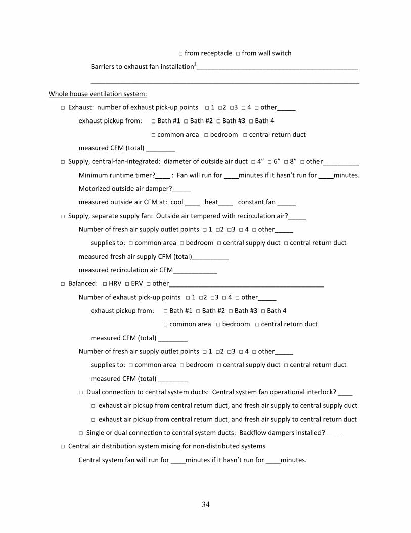
Whole house ventilation system:
□ Exhaust: number of exhaust pick‐up points □ 1 □2 □3 □ 4 □ other_____
exhaust pickup from: □ Bath #1 □ Bath #2 □ Bath #3 □ Bath 4
□ common area □ bedroom □ central return duct
measured CFM (total) ________
□ Supply, central‐fan‐integrated: diameter of outside air duct □ 4” □ 6” □ 8” □ other__________
Minimum runtime timer?____ : Fan will run for ____minutes if it hasn’t run for ____minutes.
Motorized outside air damper?_____
measured outside air CFM at: cool ____ heat____ constant fan _____
□ Supply, separate supply fan: Outside air tempered with recirculation air?_____
Number of fresh air supply outlet points □ 1 □2 □3 □ 4 □ other_____
supplies to: □ common area □ bedroom □ central supply duct □ central return duct
measured fresh air supply CFM (total)__________
measured recirculation air CFM____________
□ Balanced: □ HRV □ ERV □ other__________________________________________
Number of exhaust pick‐up points □ 1 □2 □3 □ 4 □ other_____
exhaust pickup from: □ Bath #1 □ Bath #2 □ Bath #3 □ Bath 4
□ common area □ bedroom □ central return duct
measured CFM (total) ________
Number of fresh air supply outlet points □ 1 □2 □3 □ 4 □ other_____
supplies to: □ common area □ bedroom □ central supply duct □ central return duct
measured CFM (total) ________
□ Dual connection to central system ducts: Central system fan operational interlock? ____
□ exhaust air pickup from central return duct, and fresh air supply to central supply duct
□ exhaust air pickup from central return duct, and fresh air supply to central return duct
□ Single or dual connection to central system ducts: Backflow dampers installed?_____
□ Central air distribution system mixing for non‐distributed systems
Central system fan will run for ____minutes if it hasn’t run for ____minutes.

35
Footnotes to Checklist:
1 Half‐baths are those that have a toilet and/or sink only, full baths also include a shower and/or tub.
2 Barriers to exhaust fan retrofit installation should consider the observed difficulties that may exist to installing an exhaust fan in a ceiling or high wall location. These difficulties may include: logical space for the fan, apparent availability of existing electrical power and access for fishing wires; logical space for a switch, or will a fan with an integrated occupancy sensor be required; space and access for routing exhaust duct to outside; interior finishes that are more difficult to work with such as tile; presence of hazardous materials such as lead and asbestos; etc. Use separate sheet if necessary.
3 Kitchens must have a ducted range hood that exhausts directly to outdoors, or another general kitchen exhaust point not in an area susceptible to grease pickup over the range. Recirculating range hoods do not meet the local exhaust requirement.

DOE/GO-000000-0000 ▪ Month Year
Printed with a renewable-source ink on paper containing at least 50% wastepaper, including 10% post-consumer waste.