Local Area Networking Chapter 8. Knowledge Concepts Components of a LAN Transmission media Transport...
153
Local Area Networking Chapter 8
-
date post
19-Dec-2015 -
Category
Documents
-
view
221 -
download
0
Transcript of Local Area Networking Chapter 8. Knowledge Concepts Components of a LAN Transmission media Transport...

Local Area Networking
Chapter 8

Knowledge Concepts
Components of a LAN Transmission media Transport Access methods Topologies Interconnection VLANs Switches and routers

Important Vocabulary
LAN Cabling system Broadband vs
baseband CSMA/CD Token Tree ISPF, RIP BGP-4
Bus Ring Star Switch Vlan Bridge Router learning Static vs dynamic
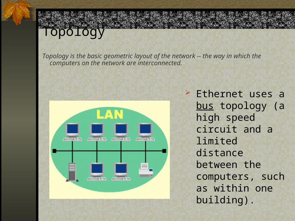
Topology
Topology is the basic geometric layout of the network -- the way in which the computers on the network are interconnected.
Ethernet uses a bus topology (a high speed circuit and a limited distance between the computers, such as within one building).
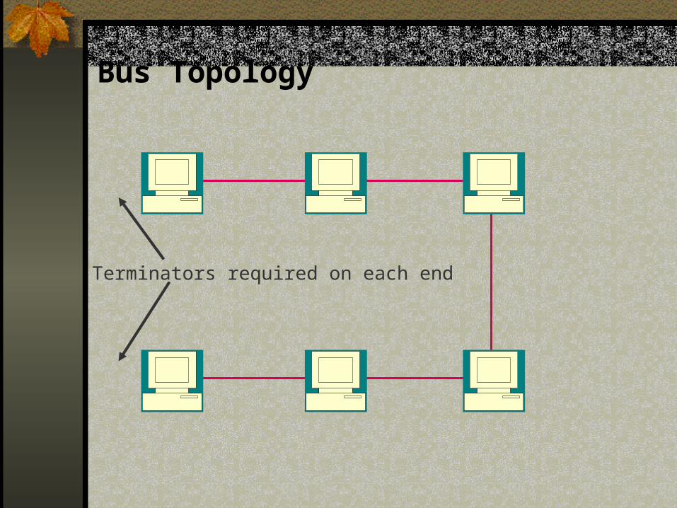
Bus Topology
Terminators required on each end

Ring Topology
Data Flow
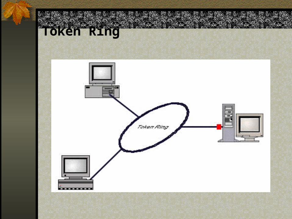
Token Ring

Star Topology
Wiring Hub
Preferred method for today’s LANs

Media Access Control Ethernet uses a contention-based
technique called Carrier Sense Multiple Access with Collision Detection (CSMA/CD)
If two computers attempt to transmit at the same time, they detect the collision, send a jamming signal, wait a random amount of time, then re-broadcast.

Node Number/Access Determines Type

Most of the World Uses Ethernet

Ethernet Tree Topology
•Each hub broadcasts to own segment•Misbehaving nodes will be shut off by the hub

Throughput
•CSMA/CD works well for small numberOf nodes per wire
•Throughput defined as useful data thatCan go across wire
•PPS (packet per sec) or percentUtilization of wire speed

LANs Cheaper as Nodes Increase

Break-point

Network Servers: Everything You Wanted to Know But Were Afraid to Ask! Servers use multiple processors
Very important to access-intensive operations
Multiple processors provide 50% improvement
Buses provide backbone internal support for data transfer
RAM provides a buffer for operations

LAN Operating System Functions Optimized I/O
One of the main services provided by a server is disk access. Disk access consists of three components: seek, latency, and transfer.
I/O optimization attempts to reduce one or more of these disk access components.
Disk Configurations One of the functions of an OS is to implement a file
system. This involves allocating and deallocating disk space and keeping track of space allocated to each file.
Partitioning Sometimes it is beneficial to divide a single disk
drive in two or more partitions; each partition can be managed separately

LAN Operating System Functions (cont.)
Single Disk Volume A volume is a logical disk (a partition or collection of partitions) or
physical disk that has been formatted and can be used to store data by an OS.
Multiple Disk Volumes or Volume Sets Most LAN OSs allow multiple partitions or disks to be combined to
form a single logical partition. A volume created from multiple partitions is called a volume set.
RAID Level 0—Striping without parity Another capability provided with some LAN OSs is called a Redundant
Array of Inexpensive Disks (RAID) Level 0 or striping without parity. Multiple partitions on different disks can be combined to proved a single logical disk; striping with parity differs from a volume just described in that data is written to all partitions simultaneously.

Fault Tolerance
A LAN with fault tolerance allows the server to survive some failures that would ordinarily be disabling. Fault tolerance usually is provided by a combination of backup hardware components and software capable of using the backup hardware.
A level of fault tolerance also can be provided by using redundant arrays of inexpensive disks (RAID). There are six levels of RAID, but for fault tolerance we are concerned only with RAID Level 1 and RAID Level 5.

It’s a RAID!
Disk arrays improve performance and redundancy
RAID (Redundant Array of Inexpensive Disks) is a method used to write across (stripe) multiple disks to improve performance and fault tolerance
RAID 1 and 5 most popular but all have problems

RAID
Disk 1 Disk 2
File
RAID 1--Mirrors data between disks
RAID 0--Stripes data between disks

Mirrored Disk Drives
Controller 1 Controller 2
File 1 File 1
File 2 File 2
DuplexedControllers
1 2

Raid Level 5 Technology
File 1 Part 1 File 1 Part 3File 1 ParityFile 1 Part 2
File 2 Part 2 File 2 Part 3 File 2 Part 1 File 1 Parity
Server
1 2 3 4

A Fault-Tolerant Duplexed Server
Dedicated High-SpeedConnection
Duplexed Servers
Disk Drive Disk Drive
Mirrored Disk Drives

Backup Software
The software used to perform the backups is as important as the hardware. Backup software is responsible for reading the files being backed up and writing them to the backup device.
Backup devices often come with a backup/restore program (both capabilities are contained on one program), and most LAN system software includes a backup/restore module.
Some LAN administrators choose to purchase a separate, more functional backup system than the LAN or backup device versions.

Immediate and Recurring Costs of a LAN
Equipment upgrades
Documentation
Installation of cabling
System software installation
Creating user environments
Space required for new equipment
LAN management—personnel costs
Consumable supplies—toner, paper, etc.
Immediate Costs
Recurring Costs
Training users, operators, administrators
Site preparation
Hardware installation
Installing applications
Testing
Supplies and spares
Hardware and software maintenance
Training new users, administrators

Basic LAN Management Tasks
Add, delete users and groups
Set user environment
Install/remove printers
Maintain printers
Add/change/delete hardware
Add/change/delete hardware
Plan and implement changes
Make backups
Carry out recovery as necessary
Plan capacity needs
Serve as liaison with other network administrators
User/Group Oriented
General
Set user/group security
Solve user problems
Setup user/printer environment
Manage print jobs
Establish connections with other networks
Diagnose problems
Maintain operating procedures
Educate users
Monitor the network for problems and to gather statistics for capacity planning
Printer Oriented
Hardware/Software Oriented

Backup Devices
Removable Disk Drives Manual intervention is necessary for changing disk
cartridges, whereas some tape backup system provide tapes with much higher storage capacity and with automatic tape changing.
Hard-Disk Drives The arguments for and against this alternative are
much the same as those for diskettes. The major difference is that the capacity of hard-disk drives is greater than that of diskettes.

Backup Devices (cont.)
Optical Disk Drives Optical disk drives are gaining popularity as input,
output, and backup devices. The reasons for this are their decreasing costs and large storage capacity.
Magnetic Tape Drives A magnetic tape drive is the usual choice for a
backup device. Magnetic tapes are less expensive than the other options. They hold large volumes of data, are easy to use and store, and generally provide good performance.

Primary Backup Technologies
Diskette backup
Hard drive, fixed
Hard drive, removable cartridge
Tape backup, 4mm or 1/4 inch
Tape backup, 8mm or VCR
Tape backup, 9-track
Optical drives
Digital versatile disks (when available)
1.44 MB
Multiple capacities
40 MB to over 1 G
To 15 GB
160 MB
2.2 GB
To 2.2 GB
To 100 MB
To 4 GB
10-14 GB
2.88 MB
60 MB
500 MB
15 GB
20 MB
150 MB
1.2 GB
70 GB (compressed)

Backup Functions
Back up all files
Differential backup
Back up all files modified since a particular date
Back up by directory
Back up automatically by time or calendar
Back up all but a list of files to be excluded
Start backup from workstation or server
Back up by interface to a database
Back up using wildcard characters in file names
Incremental backup
Maintain index on tape and disk
Maintain cross-reference of tape serial numbers and backup
Back up manually
Back up by list of files
Back up by index
Compress data
Back up multiple volumes
Generate reports

Gateways
Gateways operate at the network layer and use network layer addresses in processing messages.
Gateways connect two or more LANs that use the same or different (usually different) data link and network protocols. They may connect the same or different kinds of cable.
Gateways process only those messages explicitly addressed to them.

Gateways
Gateways translate one network protocol into another, translate data formats, and open sessions between application programs, thus overcoming both hardware and software incompatibilities.
A gateway may be a stand-alone microcomputer with several NICs and special software, a FEP (Front End Processor) connected to a mainframe computer, or even a special circuit card in the network server.

Gateways
One of the most common uses of gateways is to enable LANs that use TCP/IP and Ethernet to communicate with IBM mainframes that use SNA.
The gateway provides both the basic system interconnection and the necessary translation between the protocols in both directions.

Gateways

Classic SNA Architecture
3270
Mainframe computer
modem
modem
3274 cluster controller
3274 cluster controller
3745 front-end processor
3270 terminals
3270 terminal
327032703270
3270 terminals
327032703270
GOLDMAN & RAWLES: ADC3e FIG. 09-24

Standalone PC 3270 Terminal Emulation
3270
Mainframe computer
modem modem
modem
modem
3274 cluster controller
3274 cluster controller
3745 front-end processor
3270 terminals
3270 terminal
PC with installed 3270 protocol
conversion hardware and software
PC with installed 3270 protocol
conversion hardware and software
327032703270
3270 terminals
327032703270
GOLDMAN & RAWLES: ADC3e FIG. 09-25

LAN-based SNA Gateways
3270
Mainframe computer
Remote PC or asynchronous "dumb"
terminal without any 3270 protocol conversion
hardware or software
modem
modem
cluster controller
cluster controller
front-end processor
3270 terminal
local gateway PC with 3270 hardware and software installed.
32703270
3270
Synchronous modems
3270
asynchronous modem
asynchronous modem
asynchronous modem
Remote PC or asynchronous "dumb"
terminal without any 3270 protocol conversion
hardware or software
Standalone protocol converter which
emulates both 3270 terminals and a 3174
cluster conntroller
Remote gateway PC with both 3270 terminal emulation
as well as 3274 cluster controller
emulation hardware and software
Standalone 3270 protocol
converter
asynchronous modem
GOLDMAN & RAWLES: ADC3e FIG. 09-26

SNA/LAN Incompatibilities Yield Multiple Networks
CSU/DSUT-1
MUX
Source routing bridge CSU/DSU
T-1 MUX
Source routing bridge
1.544 Mbps
Token ring LAN
PCPC
CSU/DSUMUX9.6 Kbps
3270
Mainframe computer
Front-end processor
Cluster controller
3270 terminal
Corporate Headquarters Branch Office
SNA Network
Local Area Network
Gateway
CSU/DSU MUXCluster
controller
Token ring LAN
GOLDMAN & RAWLES: ADC3e FIG. 09-30

TCP/IP Encapsulation
CSU/DSUT-1
MUX CSU/DSUT-1
MUX
Router with TCP/IP support
and source route bridging for token ring
T-1 1.544 Mbps
Token ring LAN
PCPC
3270
Mainframe computer
Front-end processor
Cluster controller
3270 terminal
Corporate Headquarters Branch Office
Gateway
Cluster controller
Token ring LAN
Router with TCP/IP support
and source route bridging for token ring
GOLDMAN & RAWLES: ADC3e FIG. 09-32

Switched Media Technologies
Over the past few years, there has been a major change in the way we think about LANs and backbone networks. LANs have traditionally used multipoint circuits, and WANs have traditionally used point-to-point circuits.
As the shared circuits in LANs and BNs (Backbone Networks) have become overloaded with traffic, networks are starting to use switched point-to-point circuits rather than shared multipoint circuits.

Switched Ethernet
The concept behind switched ethernet - and all switched media technologies - is simple; replace the LAN hub with a switch. Each computer now has its own dedicated point-to-point circuit.
Switched ethernet dramatically improves LAN performance. However, since much of the network traffic is to and from the server, the circuit to the server is often the network bottleneck.

Switched Ethernet

Switched Ethernet
One obvious solution is to increase the number of connections from the server to the switch so that traffic now can reach the server on several circuits.
Other solutions include: Full Duplex Ethernet (full duplex over traditional
10Base-T). 10/100 Switched Ethernet (combines 10Base-T
and 100Base-T). This is often used to provide 10 Mbps to the clients and 100 Mbps to the server.

Full Duplex Ethernet

Switched Ethernet
Switched Ethernet at Fish & Richardson

Switched Ethernet Site Networks
No Maximum Distance Spans
Hierarchies and Single Possible Paths
High Speeds and Low Prices

Ethernet Switched Networks
There are Distance Limits Between
Pairs of Switches 100 meters with UTP Longer with optical fiber
MaximumSeparation
100 m with UTPLonger with optical fiber
EthernetSwitch

Hierarchies
Ethernet Switches Must be Arranged in a Hierarchy Root is the top-level
EthernetSwitch
Root

Hierarchies
Usually, Fastest Switches are at the Top (Root)
GigabitEthernetCampusSwitch
100Base-XBuilding Switch
10Base-TWorkgroup
Switch

Hierarchies
Vulnerable to Single Points of Failure Switch or Link (trunk line between switches) Divide the network into pieces
X XEthernetSwitch

Hierarchies
Single Possible Path Simplifies Switch Forwarding Decisions When frame arrives, only one possible output port (no multiple
alternative routes to select among) Switch sends frame out that port
SimpleForwarding
DecisionEthernetSwitch

Hierarchies
Switches allow only a single path for each MAC destination address Associated with a single port on each
switch So switch forwarding table has one and
only one row for each MAC address
EthernetSwitch
AddressA3..B2..
Port35

Hierarchies
Ethernet switch only has to find the single row that matches the destination MAC address
Only has to examine half the rows on average; less if the table is alphabetized
Comparison at each row is a simple match of the frame and row MAC addresses
AddressA3..B2..
Port35

More on Switched Ethernet
Switch LearningPurchase ConsiderationsVLANsIntelligent Switched Network Design

How Much of a Packet Does a Switch Need?

Switch Learning
Switch Forwarding Table has Address-Port Pairs
Manual Entry is Too Time Consuming Many addresses Addresses change
Solution: Learn addresses automatically
AddressA3..B2..
Port35

Switch Learning
Every Few Minutes, Switch Erases Switch Forwarding Table To eliminate obsolete information Relearning is very fast
Address Port
A1 BF C9
EthernetSwitch
Erased

Switch Purchasing Decisions
Maximum Number of MAC address-port entries Small switches may not be able to store
many MAC addresses
For addresses that cannot be stored, switch must act like a hub, broadcasting and so creating latency
AddressA1C9
Port15

Switch Purchasing Decisions
Queue Size Incoming frames are placed in queues if they
cannot be processed immediately May have several queues
If queues are too small, frames will be lost during brief peak loads
SwitchMatrix
QueuesOutputPorts
InputPorts
Frames

Switch Purchasing Decisions
Switching Matrix Receives input from multiple input ports,
via queues Switches each frame to the correct output
port
QueuesOutputPorts
InputPorts
FramesSwitch Matrix

Switch Purchasing Decisions
Reliability through Redundancy Redundant power supplies and cooling fans
May even have redundant switch matrix for backup
SwitchMatrix
QueuesOutputPorts
InputPorts
Frames

Switch Purchasing Decisions
Manageability Can be managed remotely from the network
administrator’s desk Network administrator can check on status of switch
Network administrator can modify how the switch functions
Remote management greatly reduces labor
SwitchMatrix
QueuesOutputPorts
InputPorts
Frames

Multiple Access

Network Segmentation

Network Segmentation

Switch Connections

Dedicated Segments

Routing Types

Routing and Addresses
GOLDMAN & RAWLES: ADC 3e FIG: 07-08
Address ProcessingFrom source workstation to default gateway router found on LAN A:
From LAN A router to next hop router towards ultimate destination as noted in routing table:
From LAN B router to locally attached ultimate destination workstation:
destination 0020AF A3580A
source 0020AF A24890
source 0020AF A3581F
source 0000C0 C04445
destination 0000C0 C13745
destination 0020AF A2492B
Data-Link
Data-Link
Data-Link
destination B:22
source A:16
Network
destination B:22
source A:16
Network
destination B:22
source A:16
Network
Source Workstation
Ultimate Destination Workstation
Network Address: A:16 Physical Address: 0000C0 C04445
Network Address: B:22 Physical Address: 0000C0 C13745
Network Address: C:1 Physical Address: 0020AF A3581F
Network Address: A:1 Physical Address: 0020AF A3580A
Network Address: B:1 Physical Address: 0020AF A24890
Network Address: C:12 Physical Address: 0020AF A2492B
default gateway router
InternetworkLink
LAN A
LAN B
Physical Topology
router

Network Address Translation
NIC address: 192.75.16.65
Workstation address: 192.168.1.22 port 7586
private network
Workstation address: 194.196.16.43 Port: 80
NATPacket: Source: 192.168.1.22 Port: 7586 Destination: 194.196.16.43 Port: 80
Packet: Source: 194.196.16.43 Port: 80 Destination: 192.168.1.22 Port: 7586
Packet: Source: 192.75.16.65 Port: 61001 Destination: 194.196.16.43 Port: 80
Packet: Source: 194.196.16.43 Port: 80 Destination: 192.75.16.65 Port: 61001
NAT Source/Destination Table
Private Source IP Address Private Source Assigned Port ID
192.168.1.22
192.168.1.23
192.168.1.24
192.168.1.25
61001
61002
61003
61004
..and so on.. ..and so on..
INTERNET
GOLDMAN & RAWLES: ADC3e FIG. 09-13

Router Installations
Branch Office router
Branch Office router
Dial-up router
Dial-up router
Central Site router
All configuration (multiple LAN and WAN links) and routing information
contained here.
1 LAN link 1 WAN link Only connects to Corporate Headquarters
as needed
1 LAN link 1 WAN link
Only decides whether packet destination is local or not.
LEA
SE
D
LIN
E o
r fr
ame
rela
y
DIA
L-U
P li
ne s
uch
as I
SD
N
CORPORATE HEADQUARTERS
local LAN local LAN local LAN
local LAN
local LAN
GOLDMAN & RAWLES: ADC3e FIG. 09-14

Routing Evolution Scenarios
LAN A
edge switch
LAN switch
edge switch
Enterprise Network
route server
Route Servers
ENTERPRISE NETWORK ROUTING INFORMATION
ROUTING AND SWITCHING LAYER
Distributed Routing
Distinct Layer 2 Switching and Layer 3 Routing
SWITCHING LAYER
LAN switch
ROUTING LAYER
router
LAN B
LAN C
LAN A
multilayer switch
multilayer switch
Enterprise Network
ENTERPRISE NETWORK ROUTING AND SWITCHING LAYER
LAN B
LAN C
LAN A
LAN B
LAN C
Enterprise Network
ENTERPRISE NETWORK
GOLDMAN & RAWLES: ADC3e FIG. 09-18

IP Address Classes
GOLDMAN & RAWLES: ADC3e FIG. 07-15
Class ID
1 1 0
(3 bits)
0
(1 bit)
1 0
(2 bits)
126 different Network IDs
(7 bits)
Network ID Host ID
(24 bits)
16,777,214 different Host IDs
CLASS A
Class IDCLASS C
Class IDCLASS B Host ID
(16 bits)
65,534 different Host IDs16,382 different Network IDs
(14 bits)
Network ID
2,097,150 different Network IDs
(21 bits)
Network ID Host ID
(8 bits)
254 different Host IDs
address packet totals to 32 bits
address packet totals to 32 bits
address packet totals to 32 bits
NOTE: The contents of each CLASS ID segment is constant for each CLASS.

IP Address Instruction
GOLDMAN & RAWLES: ADC3e FIG. 07-12
Dotted Decimal IP Address:
Binary IP Address:
110 234 9 202. . .
01101110 11101010 00001001 11001010
110 234 9 202Decimal Representation of Each Octet:

Masks
IP Addresses are Always Paired with a Second 32-bit Number Called a Mask
Two Types: Network Masks and Subnet Masks Network Mask Tells the Length of the Network
Part Subnet Mask Tells the length of the Network
Plus Subnet Parts (not just subnet part) IP Address will be paired with one or the other,
but not both simultaneously

Using Subnet Masks
GOLDMAN & RAWLES: ADC3e FIG. 07-14
IP Address (Dotted Decimal):
IP Address (Binary):
110 234 9 202. . .
01101110 11101010 00001001 11001010
01101110 11101010 00001001 11001010
segment address
node address
Original Binary IP Address:
11111111 00000000 00000000 00000000
01101110 11101010 00001001 11001010
Binary SubNet Mask:
Resulting Division:
Applying SubNet Mask: 255.128.0.0
01101110 11101010 00001001 11001010
segment address
node address
Original Binary IP Address:
11111111 11111111 00000000 00000000
01101110 11101010 00001001 11001010
Binary SubNet Mask:
Resulting Division:
Applying SubNet Mask: 255.255.0.0

Multiple Network Protocols
GOLDMAN & RAWLES: ADC 3e FIG: 07-28
2 NICs. IPX/SPX and TCP/IP supported. Multi-protocol routing enabled
NetWare Servers
Windows NT Server
NetWare Clients
Windows NT/2000 Server
Windows NT/2000 Clients
Windows '9x Client
IPX/SPX
TCP/IP
Multi- protocol routing
NIC 1
NIC 2

Standards for Web Server Access
Layer Standard
Application HyperText Transport Protocol (HTTP)
Transport Transmission Control Protocol (TCP)
Internet Internet Protocol (IP);Messages are packets
Data Link Point-to-Point Protocol (PPP); Messages are frames
Physical Modem, telephone standards

OSI Networking Model
Layer 7Application
Layer 6Presentation
Layer 5Session
Layer 4Transport
Layer 3Network
Layer 2Data Link
Layer 1Physical
Application & OS Network Client Application & OS
Bit stream connectionprotocol
Packet construction, Transmission, &
reception
Packet control& sequencing error
control
Connection betweenClient & server
Data compression& decompression; dataEncryption/decryption
Provide network services
To OS through network client
Network Wiring & specifications
54321 12345
Session
Packets
Network card & drivers
Data Packet with Header & Trailer

Protocols
A protocol is a standard for communication between peer processes, that is, processes at the same layer, but on different machines
HTTP: Browser and webserver application programs are at the same layer but on different machines
AppApp AppAppHTTPMessage

Protocols A protocol is a standard for
communication between peer processes, that is, processes at the same layer, but on different machines
TCP, IP, and PPP all have “protocol” as their final “P;” they are all protocols
TCP (Transmission Control Protocol) is the protocol governing communication between transport layer processes on two hosts
TransTrans TransTransTCPMessage

Layered Communication
Layers work togetherEncapsulation and De-encapsulation

Indirect Communication
Application programs on different machines cannot communicate directly They are on different machines!
BrowserBrowser
TransTrans
IntInt
DLDL
PhyPhy
User PC
Web AppWeb App
TransTrans
IntInt
DLDL
PhyPhy
Webserver
HTTP RequestHTTP Request

Layer Cooperation on the Source Host
Application layer process passes HTTP-request to transport layer processApplicationApplication
TransportTransport
InternetInternet
Data LinkData Link
HTTP RequestHTTP Request
PhysicalUser PC

Layer Cooperation on the Source Host
Transport layer makes TCP segments HTTP message is the data field Adds TCP header fields shown earlier Transport process “encapsulates” HTTP
request within a TCP segment
HTTP RequestHTTP Request TCP-HTCP-H
TCP Segment
DataField
TCPHeader

Encapsulation
Encapsulation is delivering a message in the data field of another message TCP encapsulates HTTP request messages
Can also encapsulate other types of messages
HTTP RequestHTTP Request TCP-HTCP-H
TCP Segment
DataField
TCPHeader

Layer Cooperation on the Source Host Transport layer process passes the
TCP segment down to the internet layer process
ApplicationApplication
TransportTransport
InternetInternet
Data LinkData Link
TCP segmentTCP segment
PhysicalUser PC

Layer Cooperation on the Source Host
Internet Layer Process Encapsulates TCP Segment within an IP packet An IP packet to deliver a TCP segment has
a TCP segment in its data field
TCP segmentTCP segment IP-HIP-H
Data IP Packet
DataField
IPHeader

Layer Cooperation on the Source Host
The internet layer process passes the IP packet to the data link layer process Internet layer messages are called packets
ApplicationApplication
TransportTransport
InternetInternet
Data LinkData Link
IP packetIP packet
PhysicalUser PC

Layer Cooperation on the Source Host
Data Link Layer Encapsulates IP Packet Within a PPP Frame Data link layer messages are called
frames Data PPP frame has IP packet in data
field
PPP Frame Encapsulating an IP Packet
PPP-TPPP-T IP packetIP packet PPP-HPPP-H

Layer Cooperation on the Source Host
The data link layer process passes the PPP frame to the physical layer process, which delivers it to the physical layer process on the first router, one bit at a time (no message at the physical layer)
ApplicationApplication
TransportTransport
InternetInternet
Data LinkData Link
Physical (10110 …)User PC
PPP framePPP frameTo firstrouter

PPP-TPPP-T
Layer Cooperation on the Source Host
Recap: Adding Headers and Trailers:
ApplicationApplication
TransportTransport
InternetInternet
Data LinkData Link
HTTP msgHTTP msg
PhysicalUser PC
HTTP msgHTTP msg TCP-HTCP-H
HTTP msgHTTP msg TCP-HTCP-H IP-HIP-H
HTTP msgHTTP msg TCP-HTCP-H IP-HIP-H PPP-HPPP-H

Layer Cooperation on the Source Host Encapsulation in Layering
Whenever a process at Layer N (the application, transport, internet, or data link layer) creates a message,
That Layer N process passes the message down to the next-lower-layer process, the process at layer N-1
The N-1 process encapsulates the Layer N message by placing it in the data field of a Layer N-1 message and adding headers and perhaps trailers to create the full Layer N-1 Message

Layer Cooperation on the Source Host
Small but important detail on naming Layer 3 (internet) messages are called
packets IP message is a packet
Layer 2 (data link) messages are called frames PPP message is called a frame

Layer Cooperation: Destination Host
Destination host reverses processes on the sending host Delivers HTTP message to the webserver application program
ApplicationApplication
TransportTransport
InternetInternet
Data LinkData Link
PhysicalUser PC Webserver

Layer Cooperation: Destination Host
Successively pass up layer messages
ApplicationApplication
TransportTransport
InternetInternet
Data LinkData Link
IP-PacketIP-Packet
DL-Frame (protocol unknown)containing IP packet in data field
DL-Frame (protocol unknown)containing IP packet in data field
PhysicalFinal Router Webserver
Data link layer program processes the data link frame’s header and trailer, deencapsulates the IP packet, and passes the IP packet to the next higher layer, the internet layer

Layer Cooperation: Destination Host Successively pass up layer messages
Other layers pass successive data fields (containing next-layer messages) up to the next higher layer
ApplicationApplication
TransportTransport
InternetInternet
Data LinkData Link
HTTP msgHTTP msg
TCP segmentTCP segment
IP-PacketIP-Packet
DL-Frame (protocol unknown)DL-Frame (protocol unknown)
PhysicalFinal Router Webserver

Layer Cooperation: Destination Host Successively pass up layer messages
Other layers process headers & trailers, pass up message in data field
ApplicationApplication
TransportTransport
InternetInternet
Data LinkData Link
PhysicalFinal Router Webserver
PPP-TPPP-T
HTTP msgHTTP msg
HTTP segHTTP seg TCP-HTCP-H
HTTP msgHTTP msg TCP-HTCP-H IP-HIP-H
HTTP msgHTTP msg TCP-HTCP-H IP-HIP-H PPP-HPPP-H
IP Packet
TCPsegment
HTTP msg

Router’s Use of Data-Link and Network Layer Addresses
Header Data Trailer
MAC Layer addresses
Used for point-to-point connections
Network Layer (IP, IPX) addresses
Used for end-to-end connections
MAC address of router which last processed this packet
MAC address of next HOP router
Addresses change with each HOP
Network layer address of original workstation
Network layer address of ultimate destination workstation
Addresses do NOT change
Source Address
Destination Address
Source Address
Destination Address
Network layer data field containing upper layer protocols and user data
Used by router to determine best path according to information contained in routing table.
(Embedded Network Layer Packet)
Data Link Layer Frame
GOLDMAN & RAWLES: ADC3e FIG. 09-04

Layer Cooperation on the First Router
So far, we have only looked at hosts But deencapsulation and encapsulation
also occur on EACH router
Frame arrives at a port on the first router Port’s data link layer process receives
the PPP frame containing an IP packet
Data LinkData Link Data LinkData Link
InternetInternet
PPP FramePPP Frame
First Router

Layer Cooperation on the First Router
Incoming Data Link Process on the Router Deencapsulates the IP packet from the PPP frame Passes the IP packet to the router’ internet layer
process
Data LinkData Link Data LinkData Link
InternetInternetIP PacketIP Packet
First Router
Incoming Port on First Router

Layer Cooperation on the First Router
Routers only have physical, data link, and internet layer processes So internet layer process is the highest-layer
process on a router for router forwarding Internet layer process decides where to send the
packet next: another router or the destination host
Data LinkData Link Data LinkData Link
InternetInternet
First Router

Layer Cooperation on the First Router
Internet layer process passes IP packet to data link layer process on the selected output port that will carry the IP packet to the next router or the destination host
Data LinkData Link Data LinkData Link
InternetInternet
First Router
IP Packet
Selected Output Port on First Router

Layer Cooperation on the First Router
The data link and physical layer process on the selected port sends the frame encapsulating the IP packet onto the next router (or destination host)
InternetInternet
Data LinkData Link
InternetInternet
Data LinkData LinkFrame
Selected Output PortOn First Router
Input PortOn Next Router
(Or Destination Host)
PhysicalLayer

Layer Cooperation on the First Router
For router forwarding, routers only use physical, data link, and internet processes
Routers First Receive Frames Receiving interface deencapsulates the IP
packet, passes the packet to the internet layer process
Routers Then Send Frames Out On a different output interface (port) This requires encapsulating of the IP packet
in a data link layer frame

Domain Name System (DNS)
Subtlety Organizations or ISPs have local DNS
hosts These hosts must know only local host
names and IP addresses For other host names, local DNS host
passes request to another DNS host
User PCInternetLayer
Process
LocalDNSHost
RemoteDNSHost

Domain Name System (DNS)
Subtlety Remote DNS host passes information
back to the local DNS host Local DNS host passes information back
to user PC Browser only talks to local DNS host
User PCInternetLayer
Process
LocalDNSHost
RemoteDNSHost

Autoconfiguration
Every computer attached to the Internet is a host Including desktop PCs
Every host must have an IP address Some hosts, such as routers and
webservers, get permanent IP addresses So that they can be found easily

Autoconfiguration
User PCs do not need permanent IP addresses They only need to be found within a use
session They usually are given temporary IP
addresses each time they use the Internet They may get a different IP address each
time they use the Internet

Autoconfiguration
Request-Response Cycle User software requests IP address for the user
PC in Autoconfiguration Request message Autoconfiguration Response message contains
temporary IP address to use in current session
User PCAutoconfiguration
Host
AutoconfigurationRequest
TemporaryIP Address in
Autoconfiguration Response

Autoconfiguration
Most popular autoconfiguration protocol is DHCP Dynamic Host Configuration Protocol Built into Windows after Win 3.1 Supplies host with temporary IP address
DHCP can give more information too Usually gives IP address of a default gateway
(Microsoft terminology for router) Can give IP address of a local DNS host Can give other information

FDDI
•Based on the token ring design using 100 Mbps fiber connections.
• Allows for two concentric rings - inner ring can support data travel in opposite direction or work as backup.
• Token is attached to the outgoing packet, rather than waiting for the outgoing packet to circle the entire ring.

Gigabit Ethernet (IEEE802.3z)
Similar to 100Base-X, 1000Base-X is a set of standards that provide 1 Gbps. One problem with 1000Base-X is that using the standard CSMA/CD media access control on a shared network may cause problems.
For this reason, gigabit ethernet may remain primarily a backbone technology for use only in point-to-point full duplex data communications links.

Fast Ethernet at GMAC

Fiber Distributed Data Interface (FDDI)
FDDI is a token-passing ring network that operates at 100 Mbps over two-counter-rotating fiber optic cable rings.
It will support up to 500 stationson each ring

Topology
The FDDI standard assumes a maximum of 1000 stations and a 200k path that requires a repeater every 2k. The second ring is for backup.
Single attachment stations (SAS) and dual-attachment stations (DAS) are both computer that can connect to one or both of the rings, respectively.
If the cable in the FDDI ring is broken, the ring can still operate in a limited fashion.

Topology

Ring-Wrapping

DAS SAS

FDDI and Fault Tolerance
Dual ring--ring wrapping (works for 1 failure, only)
Optical by-pass— mirrors reflect light back by-pass failed device
Dual-homing—dual concentrators with one active and the other inactive

Ethernet Virtual LANs
Broadcasting Sometimes, station needs to send a frame to all
other stations; this is broadcasting
For example, servers send a frame to advertise their presence with a broadcast message every minute or so

Ethernet Virtual LANs
Broadcasting with Ethernet Switches Broadcaster sets the destination MAC
address to all ones (48 ones) When switch sees this address, it broadcasts
frame out all stations All stations read frames with this address
BroadcastFrame
EthernetSwitch

Ethernet Virtual LANs
Broadcasting is a Problem in Large Switched Networks Server broadcasts go to all stations,
creating a great deal of network traffic Create congestion
BroadcastFrame

Ethernet Virtual LANs
Ethernet switches do implement multicasting A server and the clients it serves are treated
as a single virtual LAN (VLAN) Can only communicate among themselves,
as if they were on their own LAN
Frame
MarketingVLAN Server
MarketingVLAN Client

Ethernet Virtual LANs
VLAN Benefits
VLANs reduce traffic on the switched network
Other benefits
They provide weak security because clients cannot reach all servers (easily defeated but good first line of defense)
VLANs give ease of management because if a user changes organizational membership, VLAN membership is easily changed centrally

Bad Switch Organization
One Server for All Clients All traffic goes to and from server Bottlenecks: no simultaneous conversations No major benefits compared to hub
BottleneckEthernetSwitch

Bad Switch Organization
Multiple Servers for Clients Allows simultaneous conversations Brings switching’s main benefit
EthernetSwitch

Early Site Networks
Organization LANs (subnets) based on hubs Routers link hubs Hierarchy of Routers
Router
Hub

The Switching Revolution
Switches Push Routers to the Edge Router still needed at the edge of the site network
to communicate with outside world because routers handle expensive long-distance links very well
External
Switch

The Switching Revolution
Layer 3 Switches Traditional switches operate at Layer 2; Switch based on
MAC addresses Layer 3 switches switch based on internet layer IP
addresses
External
Layer 3Switch

The Switching Revolution
Layer 3 Switches Layer 3 switches are replacing many Layer 2
switches in site networks because of their ability to switch based on IP addresses
External
Layer 3Switch

The Switching Revolution
Layer 3 Switches versus Routers Layer 3 switches are much faster than routers
Layer 3 switches cost less than routers
External
Layer 3Switch

The Switching Revolution
Layer 3 Switches versus Routers Layer 3 switches rarely support Layer 2 WAN protocols
Routers usually are still needed at the edge of the site network, to communicate with external links
External
Layer 3Switch

The Switching Revolution
Routers Forward based on IP
addresses and other internet layer addresses
Expensive and slow
Handle multiple internet layer protocols
Handle multiple LAN and WAN subnet protocols
Layer 3 Switches
Forward based on IP addresses, sometimes IPX addressesInexpensive and Fast
Do not handle multiple internet layer protocols
Do not handle multiple LAN and WAN subnet protocols

The Switching Revolution
Layer 4 Switches Examine port fields in TCP and UDP
These fields describe the application
Therefore, can switch based on application (to give priority by application, etc.)
Layer 4Switch

Congestion, Latency, and Remedies
Peak Loads
Congestion and Latency
Overprovisioning Capacity
Priority
Quality of Service
Traffic Shaping

The Peak Load Problem
Capacity Sufficient Most of the Time Otherwise, get bigger switches and trunk lines!
Brief Traffic Peaks can Exceed Capacity Frames will be delayed in queues or even lost if
queue gets fullCapacityTrafficPeak

Overprovisioning
Overprovisioning: Install More Capacity than Will be Needed Nearly All of the TimeWasteful of capacityStill, usually the cheapest solution today because of its simplicity
Overprovisioned Capacity
TrafficPeak

Priority
Assign Priorities to Frames High priority for time-sensitive applications (voice) Low priority for time-insensitive applications (e-mail) In traffic peaks, high-priority frames still get through Low-priority applications do not care about a brief delay for
their frames
High-PriorityFrame Goes
Low-Priority FrameWaits Briefly

Bridges•A bridge can be used to connect two similar LANs, such as two CSMA/CD LANs.
•A bridge can also be used to connect two closely similar LANs, such as a CSMA/CD LAN and a token ring LAN.
•The bridge examines the destination address in a frame and either forwards this frame onto the next LAN or does not.
•The bridge examines the source address in a frame and places this address in a routing table, to be used for future routing decisions.

Use of Data-Link Addressing by Bridges
Data Link Layer Frame
Data Link Header Data Link Data Field Data Link Trailer
Source Address Destination Address
Contains MAC address of original source workstation
Contains MAC address of ultimate destination workstation
Upper layer protocols including network layer address information
These addresses are used by bridges to determine whether or not packets should be forwarded across the bridge.
Data Link layer addresses are NOT changed by bridges.
GOLDMAN & RAWLES: ADC3e FIG. 09-03

Bridges Interconnect

Connecting LANs

Bridges Connect Similar

Bridge Installations
Token ring 4Mbps MAU
Token ring 4Mbps MAU
Thin EthernetTransparent
local bridge
Token ring 16Mbps MAU
10Base-T Ethernet hub
Local protocol converting (frame translating converter) bridge
CSU/DSU
Token Ring Remote bridge
Token Ring Remote bridgeCSU/DSU
Token Ring bridge with speed conversion
16Mbps token ring 4Mbps token ring
DB 25 connection
DB 25 connection56 Kbps
DDS
UTP
UTP
UTP Token RingUTP Ethernet
UT
P
thin
co
ax
GOLDMAN & RAWLES: ADC3e FIG. 09-08

Bridge & Switch Combo

Frames Are Converted

Overall Internetworking Design Strategies
20% of LAN traffic travels
between LANs
80% of LAN traffic stays on local LAN
bridge LAN B
Segmentation
Micro-Segmentation
LAN switch
FDDI modules (100 Mbps)
backbone network router
backbone network router
10BaseT module (10Mbps)
10BaseT module (10Mbps)
LAN A
Server Isolation
LAN switch or router
hub hub
Hierarchical Networking
10BaseT hub 10BaseT hub
GOLDMAN & RAWLES: ADC3e FIG. 09-01

Storage Area Network
Links to Enterprise Network or MAN
Tape Servers
GOLDMAN & RAWLES: ADC3e FIG. 09-02
RAID Disk
ArraysOptical Juke
Boxes
Fibre Channel Switch
Storage Area Network
Gigabit Ethernet
ATM Packet over SONET

Relationship Between the OSI Model and Internetworking Devices
Switch
Application
Presentation
Session
Transport
Network
Datalink
Physical
Application
Presentation
Session
Transport
Network
Datalink
Physical
OSI Model Layer LAN 1
OSI Model Layer LAN 2
Internetworking Device
Bridge
Gateway
Repeater
Router
GOLDMAN & RAWLES: ADC3e FIG. 09-05
Layer 3Switch
Layer 4
Layer 2
Switch

LAN Switches and Virtual LANs
broadcast source
LAN switch
B
B
B
broadcast source
LAN switch
LAN Switch
broadcast traffic
Broadcasts to all ports on LAN switch.
Single Switch Virtual LANs
Broadcasts only to members of Virtual LAN.
broadcast traffic
A
Virtual LAN assignments
Virtual LAN "A" is a multi-switch Virtual LAN
B
B
B
broadcast source
LAN switch
Multi-Switch Virtual LANs
A
C
C
LAN switch
C
C
Proprietary switch-to-switch communications
high-speed backbone network
A
A
A
A
A
A
A
GOLDMAN & RAWLES: ADC3e FIG. 09-19

Layer 2 vs. Layer 3 Virtual LANs: An Architectural Comparison
B
A
BB
Layer 2 Virtual LANs
A
Virtual LAN assignments
B
C
DD
C
D
Layer 2 LAN switch
Layer 2 LAN switch
routerCDB A
Virtual LAN assignments
D
C
C
A
A
All traffic between virtual LANs is forwarded to the router. Each Virtual LAN has its own connection to the router. LAN switches differentiate between Virtual LANs based upon the MAC layer address.
B
B
Layer 3 Virtual LANs
A
Virtual LAN assignments
B
D
C
D
Layer 3 LAN switch
Layer 3 LAN switch
Virtual LAN assignments
D
C
C
A
A
Routing functionality is included within the Layer 3 LAN switch. Traffic between Virtual LANs is forwarded by the Layer 3 routing functionality. Traffic within Virtual LANs is forwarded by the Layer 2 bridging functionality.
B
A routing
routing
C
D
Virtual LAN B IPX only
Virtual LAN A IP only
Virtual LAN D IP only
Virtual LAN C IPX only
Enterprise Network
Enterprise Network
GOLDMAN & RAWLES: ADC3e FIG. 09-20