
Loadline Moulded Case Circuit...
33
Loadline Moulded Case Circuit Breakers 1 Features Current ratings from 20A to 1600A Selectivity utilisation category A & B Thermal and magnetic, generator compatible and switch disconnector devices Temperature calibration options Technologically advanced design Benefits High breaking capacities Ground fault protection Accurate microprocessor controlled Wide electronic characteristic adjustment Comprehensive range of accessories Selectivity Applications Generator protection L.V. Power distribution L.V. Circuit protection Approvals IEC 60947-2 EN 60947-2 CEI EN 60947-2 NEMA AB-1 ISO 9001 The Dorman Smith Loadline MCCB range spans current ratings from 20A to 1600A and is complemented by a comprehensive range of accessories. This technologically advanced range ensures that there are no problems caused by harmonics, DC applications and temperature rise. Discrimination issues are easily resolved by simple selection of the appropriate device. All devices comply with IEC 60947-2 and EN 60947-2 and are manufactured in compliance with ISO 9001. Wherever practicable, all escutcheons are of compatible dimensions to facilitate installation and improve aesthetic appearance of the finished assembly. To meet increasing market demands Dorman Smith have introduced the Y Frame Series of MCCBs, featuring high breaking capacities with the options of ground fault protection and electronic microprocessor control. This new electronic range features selectivity utilisation category B throughout, and includes a number of complementary thermal and magnetic, generator compatible and switch disconnector devices. In addition, the range offers the option of different temperature calibrations. Contents Page No. Introduction Loadline MCCBs – Overview 2 International Compliance Information 4 Standard Series Thermal/Magnetic MCCBs G Frame 25A – 125A 8 AA/AM Frame 25A – 200A 10 Y Series Moulded Case Circuit Breakers Thermal/Magnetic Y2 Frame 20A – 125A 12 Y3 Frame 160A – 250A 14 Y5 Frame 250A – 400A 16 Y6 Frame 400A – 800A 18 Electronic Y5 Frame 250A – 400A 16 Y6 Frame 630A – 800A 18 Y7 Frame 1000A – 1250A 20 Y8 Frame 1600A 22 Ground Fault Function Y6 Frame 630A – 800A 18 Y7 Frame 1000A – 1250A 20 Y8 Frame 1600A 22 Generator Y2 Frame 20A – 125A 24 Y3 Frame 160A – 250A 24 Y5 Frame 250A – 400A 24 Y6 Frame 400A – 800A 24 Changeover Units Y6 Changeover Unit 25 Accessories and Application Data Plug-in Base Information 26 Earth Leakage Units 26 Rotary Handle Information 27 Motor Operation and Control Circuits 28 Internally Mounted Accessories 30 Characteristic Adjustment 31 Selectivity 32 Time Current Curves 32 Quality Assurance and ASTA Certification 33
Transcript of Loadline Moulded Case Circuit...

Loadline Moulded Case Circuit Breakers
1
FeaturesCurrent ratings from 20A to 1600A
Selectivity utilisation category A & B
Thermal and magnetic, generatorcompatible and switch disconnectordevices
Temperature calibration options
Technologically advanced design
BenefitsHigh breaking capacities
Ground fault protection
Accurate microprocessor controlled
Wide electronic characteristic adjustment
Comprehensive range of accessories
Selectivity
ApplicationsGenerator protection
L.V. Power distribution
L.V. Circuit protection
ApprovalsIEC 60947-2
EN 60947-2
CEI EN 60947-2
NEMA AB-1
ISO 9001
The Dorman Smith Loadline MCCB range spans current ratings from 20A to1600A and is complemented by a comprehensive range of accessories. This technologically advanced range ensures that there are no problems causedby harmonics, DC applications and temperature rise. Discrimination issues areeasily resolved by simple selection of the appropriate device. All devices complywith IEC 60947-2 and EN 60947-2 and are manufactured in compliance with ISO 9001. Wherever practicable, all escutcheons are of compatible dimensions tofacilitate installation and improve aesthetic appearance of the finished assembly.To meet increasing market demands Dorman Smith have introduced the Y FrameSeries of MCCBs, featuring high breaking capacities with the options of groundfault protection and electronic microprocessor control. This new electronic rangefeatures selectivity utilisation category B throughout, and includes a number ofcomplementary thermal and magnetic, generator compatible and switchdisconnector devices. In addition, the range offers the option of differenttemperature calibrations.
Contents Page No.
IntroductionLoadline MCCBs – Overview 2International Compliance Information 4
Standard Series Thermal/Magnetic MCCBsG Frame 25A – 125A 8AA/AM Frame 25A – 200A 10
Y Series Moulded Case Circuit BreakersThermal/Magnetic
Y2 Frame 20A – 125A 12Y3 Frame 160A – 250A 14Y5 Frame 250A – 400A 16Y6 Frame 400A – 800A 18Electronic
Y5 Frame 250A – 400A 16Y6 Frame 630A – 800A 18Y7 Frame 1000A – 1250A 20Y8 Frame 1600A 22Ground Fault Function
Y6 Frame 630A – 800A 18Y7 Frame 1000A – 1250A 20Y8 Frame 1600A 22Generator
Y2 Frame 20A – 125A 24Y3 Frame 160A – 250A 24Y5 Frame 250A – 400A 24Y6 Frame 400A – 800A 24Changeover Units
Y6 Changeover Unit 25
Accessories and Application DataPlug-in Base Information 26Earth Leakage Units 26Rotary Handle Information 27Motor Operation and Control Circuits 28Internally Mounted Accessories 30Characteristic Adjustment 31Selectivity 32Time Current Curves 32Quality Assurance and ASTA Certification 33
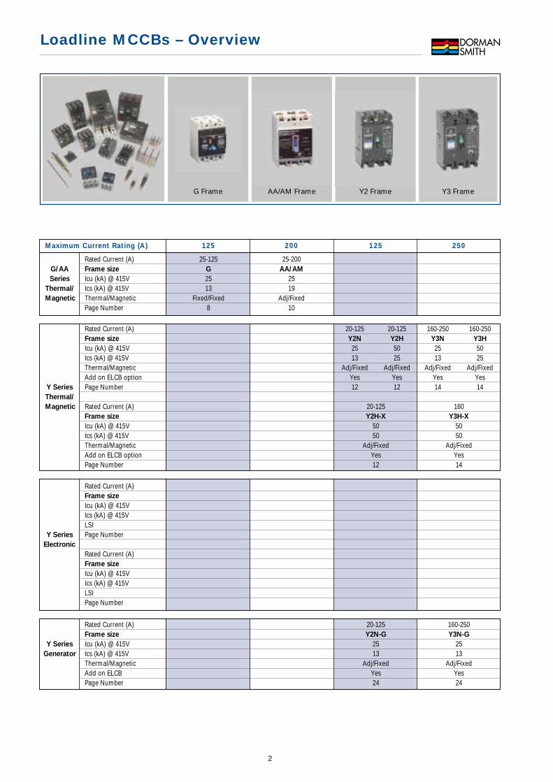
G Frame AA/AM Frame Y3 Frame
Loadline MCCBs – Overview
2
Y2 Frame
Maximum Current Rating (A) 125 200 125 250
Rated Current (A)Frame size
Icu (kA) @ 415VIcs (kA) @ 415VLSI
Y Series Page NumberElectronic
Rated Current (A)Frame size
Icu (kA) @ 415VIcs (kA) @ 415VLSIPage Number
Rated Current (A) 20-125 160-250Frame size Y2N-G Y3N-G
Y Series Icu (kA) @ 415V 25 25Generator Ics (kA) @ 415V 13 13
Thermal/Magnetic Adj/Fixed Adj/FixedAdd on ELCB Yes YesPage Number 24 24
Rated Current (A) 25-125 25-200G/AA Frame size G AA/AM
Series Icu (kA) @ 415V 25 25Thermal/ Ics (kA) @ 415V 13 19Magnetic Thermal/Magnetic Fixed/Fixed Adj/Fixed
Page Number 8 10
Rated Current (A) 20-125 20-125 160-250 160-250Frame size Y2N Y2H Y3N Y3H
Icu (kA) @ 415V 25 50 25 50Ics (kA) @ 415V 13 25 13 25Thermal/Magnetic Adj/Fixed Adj/Fixed Adj/Fixed Adj/FixedAdd on ELCB option Yes Yes Yes Yes
Y Series Page Number 12 12 14 14Thermal/
Magnetic Rated Current (A) 20-125 160Frame size Y2H-X Y3H-X
Icu (kA) @ 415V 50 50Ics (kA) @ 415V 50 50Thermal/Magnetic Adj/Fixed Adj/FixedAdd on ELCB option Yes YesPage Number 12 14

Loadline MCCBs – Overview
3
Y5 Frame Y6 Frame Y8 FrameY7 Frame
Maximum Current Rating (A) 400 800 1250 1600
Rated Current (A) 250-400 630-800Frame size Y5H Y6H
Icu (kA) @ 415V 50 50Ics (kA) @ 415V 25 25LSI Yes Yes
Y Series Page Number 16 18Electronic
Rated Current (A) 250-400 630-800 1000/1250 1600Frame size Y5J Y6J Y7J Y8K
Icu (kA) @ 415V 65 65 65 85Ics (kA) @ 415V 50 50 49 64LSI Yes Yes Yes YesPage Number 16 18 20 22
Rated Current (A) 250-400 400-800Frame size Y5H-G Y6H-G
Y Series Icu (kA) @ 415V 50 50Generator Ics (kA) @ 415V 25 25
Thermal/Magnetic Adj/Adj Adj/AdjAdd on ELCB No NoPage Number 24 24
Rated Current (A)G/AA Frame size
Series Icu (kA) @ 415VThermal/ Ics (kA) @ 415VMagnetic Thermal/Magnetic
Page Number
Rated Current (A) 250-400 400-800Frame size Y5H Y6H
Icu (kA) @ 415V 50 50Ics (kA) @ 415V 25 25Thermal/Magnetic Adj/Adj Adj/AdjAdd on ELCB option No No
Y Series Page Number 16 18Thermal/
Magnetic Rated Current (A) 250-400 400-800Frame size Y5J Y6K
Icu (kA) @ 415V 65 85Ics (kA) @ 415V 50 50Thermal/Magnetic Adj/Adj Adj/AdjAdd on ELCB option No NoPage Number 16 18
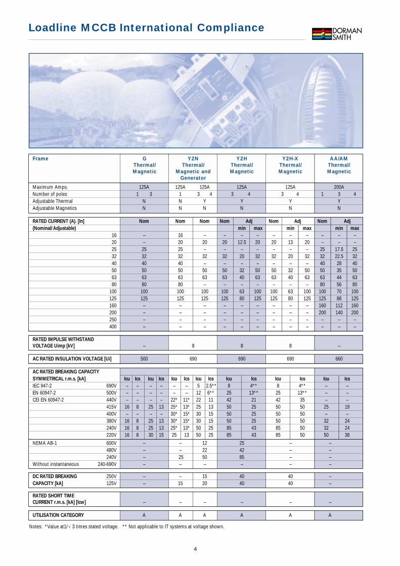
AC RATED BREAKING CAPACITY
SYMMETRICAL r.m.s. [kA] Icu Ics Icu Ics Icu Ics Icu Ics Icu Ics Icu Ics Icu Ics
IEC 947-2 690V – – – – – – 5 2.5** 8 4** 8 4** – –EN 60947-2 500V – – – – – – 12 6** 25 13** 25 13** – –CEI EN 60947-2 440V – – – – 22* 11* 22 11 42 21 42 35 – –
415V 16 8 25 13 25* 13* 25 13 50 25 50 50 25 19400V – – – – 30* 15* 30 15 50 25 50 50 – –380V 16 8 25 13 30* 15* 30 15 50 25 50 50 32 24240V 16 8 25 13 25* 13* 50 25 85 43 85 50 32 24220V 16 8 30 15 25 13 50 25 85 43 85 50 50 38
Loadline MCCB International Compliance
4
Frame G Y2N Y2H Y2H-X AA/AMThermal/ Thermal/ Thermal/ Thermal/ Thermal/Magnetic Magnetic and Magnetic Magnetic Magnetic
Generator
NEMA AB-1 600V – – 12 25 – –480V – – 22 42 – –240V – 25 50 85 – –
Without instantaneous 240-690V – – – – – –
DC RATED BREAKING 250V – – 15 40 40 –CAPACITY [kA] 125V – 15 20 40 40 –
RATED SHORT TIME
CURRENT r.m.s. [kA] [Icw] – – – – – –
UTILISATION CATEGORY A A A A A A
RATED CURRENT (A). [In] Nom Nom Nom Nom Adj Nom Adj Nom Adj
(Nominal/Adjustable) min max min max min max
16 – 16 – – – – – – – – – –20 – 20 20 20 12.5 20 20 13 20 – – –25 25 25 – – – – – – – 25 17.5 2532 32 32 32 32 20 32 32 20 32 32 22.5 3240 40 40 – – – – – – – 40 28 4050 50 50 50 50 32 50 50 32 50 50 35 5063 63 63 63 63 40 63 63 40 63 63 44 6380 80 80 – – – – – – – 80 56 80
100 100 100 100 100 63 100 100 63 100 100 70 100125 125 125 125 125 80 125 125 80 125 125 88 125160 – – – – – – – – – 160 112 160200 – – – – – – – – – 200 140 200250 – – – – – – – – – – – –400 – – – – – – – – – – – –
RATED IMPULSE WITHSTAND
VOLTAGE Uimp [kV] – 8 8 8 –
AC RATED INSULATION VOLTAGE [Ui] 500 690 690 690 660
Maximum Amps. 125A 125A 125A 125A 125A 200ANumber of poles 1 3 1 3 4 3 4 3 4 1 3 4Adjustable Thermal N N Y Y Y YAdjustable Magnetics N N N N N N
Notes: *Value at1/ 3 times stated voltage. ** Not applicable to IT systems at voltage shown.
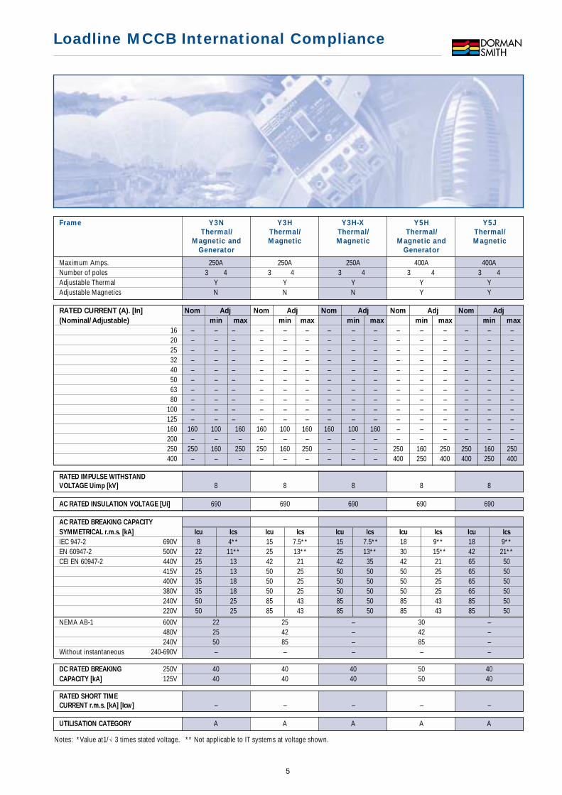
Frame Y3N Y3H Y3H-X Y5H Y5JThermal/ Thermal/ Thermal/ Thermal/ Thermal/
Magnetic and Magnetic Magnetic Magnetic and MagneticGenerator Generator
Loadline MCCB International Compliance
5
NEMA AB-1 600V 22 25 – 30 –480V 25 42 – 42 –240V 50 85 – 85 –
Without instantaneous 240-690V – – – – –
DC RATED BREAKING 250V 40 40 40 50 40CAPACITY [kA] 125V 40 40 40 50 40
RATED SHORT TIME
CURRENT r.m.s. [kA] [Icw] – – – – –
UTILISATION CATEGORY A A A A A
RATED CURRENT (A). [In] Nom Adj Nom Adj Nom Adj Nom Adj Nom Adj
(Nominal/Adjustable) min max min max min max min max min max
16 – – – – – – – – – – – – – – –20 – – – – – – – – – – – – – – –25 – – – – – – – – – – – – – – –32 – – – – – – – – – – – – – – –40 – – – – – – – – – – – – – – –50 – – – – – – – – – – – – – – –63 – – – – – – – – – – – – – – –80 – – – – – – – – – – – – – – –
100 – – – – – – – – – – – – – – –125 – – – – – – – – – – – – – – –160 160 100 160 160 100 160 160 100 160 – – – – – –200 – – – – – – – – – – – – – – –250 250 160 250 250 160 250 – – – 250 160 250 250 160 250400 – – – – – – – – – 400 250 400 400 250 400
RATED IMPULSE WITHSTAND
VOLTAGE Uimp [kV] 8 8 8 8 8
AC RATED INSULATION VOLTAGE [Ui] 690 690 690 690 690
AC RATED BREAKING CAPACITY
SYMMETRICAL r.m.s. [kA] Icu Ics Icu Ics Icu Ics Icu Ics Icu Ics
IEC 947-2 690V 8 4** 15 7.5** 15 7.5** 18 9** 18 9**EN 60947-2 500V 22 11** 25 13** 25 13** 30 15** 42 21**CEI EN 60947-2 440V 25 13 42 21 42 35 42 21 65 50
415V 25 13 50 25 50 50 50 25 65 50400V 35 18 50 25 50 50 50 25 65 50380V 35 18 50 25 50 50 50 25 65 50240V 50 25 85 43 85 50 85 43 85 50220V 50 25 85 43 85 50 85 43 85 50
Maximum Amps. 250A 250A 250A 400A 400ANumber of poles 3 4 3 4 3 4 3 4 3 4Adjustable Thermal Y Y Y Y YAdjustable Magnetics N N N Y Y
Notes: *Value at1/ 3 times stated voltage. ** Not applicable to IT systems at voltage shown.

Loadline MCCB International Compliance
6
AC RATED BREAKING CAPACITY
SYMMETRICAL r.m.s. [kA] Icu Ics Icu Ics Icu Ics Icu Ics
IEC 947-2 690V 18 9 20 10** 20 10** 45 23**EN 60947-2 500V 30 15 42 21** 35 18** 65 33**CEI EN 60947-2 440V 42 21 65 50 50 25 85 43
415V 50 25 65 50 50 25 85 50400V 50 25 65 50 65 33 100 50380V 50 25 65 50 65 33 100 50240V 85 43 100 50 85 43 125 63220V 85 43 100 50 85 43 125 63
NEMA AB-1 600V 30 – 30 –480V 42 – 50 –240V 85 – 85 –Without instantaneous 240-690V 5 5 – –
Frame Y5H-E Y5J-E Y6H Y6KElectronic Electronic Thermal/ Thermal/
Magnetic and MagneticGenerator
AC RATED INSULATION VOLTAGE [Ui] 690 690 690 690
RATED IMPULSE WITHSTAND
VOLTAGE Uimp [kV] 8 8 8 8
Maximum Amps. 400A 400A 800A 800ANumber of poles 3 4 3 4 3 4 3 4Adjustable Thermal – – Y YAdjustable Magnetics – – Y Y
RATED CURRENT (A). [In] Nom Adj Nom Adj Nom Adj Nom Adj
(Nominal/Adjustable) min max min max min max min max
50 – – – – – – – – – – – –63 – – – – – – – – – – – –80 – – – – – – – – – – – –
100 – – – – – – – – – – – –125 – – – – – – – – – – – –160 – – – – – – – – – – – –200 – – – – – – – – – – – –250 250 125 250 250 125 250 – – – – – –400 400 200 400 400 200 400 400 250 400 400 250 400630 – – – – – – 630 400 630 630 400 630800 – – – – – – 800 500 800 800 500 800
1000 – – – – – – – – – – – –1250 – – – – – – – – – – – –1600 – – – – – – – – – – – –
Notes: *Value at1/ 3 times stated voltage. ** Not applicable to IT systems at voltage shown.
UTILISATION CATEGORY B B A A
RATED SHORT TIME
CURRENT r.m.s. [kA] [Icw] 5 (0.3 sec) 5 (0.3 sec) – –
DC RATED BREAKING 250V 50 50CAPACITY [kA] 125V 50 50

AC RATED BREAKING CAPACITY
SYMMETRICAL r.m.s. [kA] Icu Ics Icu Ics Icu Ics Icu Ics
IEC 947-2 690V 20 10** 20 10** 25 19** 35 35**EN 60947-2 500V 35 18** 42 21** 45 34** 65 49**CEI EN 60947-2 440V 50 25 65 50 65 49 85 64
415V 50 25 65 50 65 49 85 64400V 50 25 65 50 85 64 100 75380V 50 25 65 50 85 64 100 75240V 85 43 100 50 100 75 125 94220V 85 43 100 50 100 75 125 94
NEMA AB-1 600V 30 – 42 65480V 50 – 65 85240V 85 – 85 125
Without instantaneous 240-690V 10 10 15 20
Frame Y6H-E Y6J-E Y7J-E Y8K-EElectronic Electronic Electronic Electronic
AC RATED INSULATION VOLTAGE [Ui] 690 690 690 690
RATED IMPULSE WITHSTAND
VOLTAGE Uimp [kV] 8 8 8 8
Maximum Amps. 800A 800A 1250A 1600ANumber of poles 3 4 3 4 3 4 3 4Adjustable Thermal – – – –Adjustable Magnetics – – – –
RATED CURRENT (A). [In] Nom Adj Nom Adj Nom Adj Nom Adj
(Nominal/Adjustable) min max min max min max min max
50 – – – – – – – – – – – –63 – – – – – – – – – – – –80 – – – – – – – – – – – –
100 – – – – – – – – – – – –125 – – – – – – – – – – – –160 – – – – – – – – – – – –200 – – – – – – – – – – – –250 – – – – – – – – – – – –400 – – – – – – – – – – – –630 630 315 630 630 315 630 – – – – – –800 800 400 800 800 400 800 – – – – – –
1000 – – – – – – 1000 500 1000 – – –1250 – – – – – – 1250 630 1250 – – –1600 – – – – – – – – – 1600 800 1600
Loadline MCCB International Compliance
7
Notes: *Value at1/ 3 times stated voltage. ** Not applicable to IT systems at voltage shown.
UTILISATION CATEGORY B B B B
RATED SHORT TIME
CURRENT r.m.s. [kA] [Icw] 10 (0.3 sec) 10 (0.3 sec) 15 (0.3 sec) 20 (0.3 sec)
DC RATED BREAKING 250V – – – –CAPACITY [kA] 125V – – – –
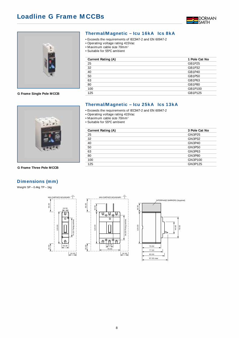
Thermal/Magnetic – Icu 16kA Ics 8kA• Exceeds the requirements of IEC947-2 and EN 60947-2• Operating voltage rating 415Vac• Maximum cable size 70mm2
• Suitable for 55ºC ambient
Current Rating (A) 1 Pole Cat No
25 GB1P2532 GB1P3240 GB1P4050 GB1P5063 GB1P6380 GB1P80100 GB1P100125 GB1P125
Thermal/Magnetic – Icu 25kA Ics 13kA• Exceeds the requirements of IEC947-2 and EN 60947-2• Operating voltage rating 415Vac• Maximum cable size 70mm2
• Suitable for 55ºC ambient
Current Rating (A) 3 Pole Cat No
25 GN3P2532 GN3P3240 GN3P4050 GN3P5063 GN3P6380 GN3P80100 GN3P100125 GN3P125
Loadline G Frame MCCBs
8
G Frame Single Pole MCCB
G Frame Three Pole MCCB
Dimensions (mm)Weight SP – 0.4kg TP – 1kg
78.5070.50
77.50
INTERPHASE BARRIERS (Supplied)
12
0.0
03
0.0
0
12
0.0
03
0.0
0
12
0.0
0
26.00
19.50
97.00 max
83.50
74
.00
Fix
ing
cent
res
94
.00
Fix
ing
cent
res
78
.60
44
.60
26.25
50
.00
20
.00
20.00
MIN EARTHED BOUNDARY
50
.00
20
.00
20.00
MIN EARTHED BOUNDARY

Accessories
Auxiliary Equipment Picture Cat No
Auxiliary Switches One changeover contact 1 GA1Two changeover contacts 1 GA2
Shunt Release assembly*
24V dc 2 GST024115V ac 2 GST115230V ac 2 GST230Accessories
Dolly padlocking facility 3 GSPFPadlock - XPLSingle pole terminal shroud 4 GS1Triple pole terminal shroud 4 GS3
*Auxiliary equipment can only be fitted within triple pole devices.GA1 or GA2 cannot be fitted if shunt release is installed.
General Purpose MCCB Enclosures• IP3X Ingress protection
Current Rating (A) Frame Size Cat No
25-125 G LLGPGDimensions (mm)
Current Rating (A) Height (mm) Width (mm) Depth (mm)25 - 125 380 202 94
3 Pole units include neutral link assembly.
Sensel Earth Leakage Units• Pre-wired, ready to install• IP3X Ingress protection• MCCB controlled via 240V shunt trip
Current Rating (A) Frame size 3 Pole
Cat No
32 G SRBGN3P3263 G SRBGN3P63100 G SRBGN3P100125 G SRBGN3P125Dimensions (mm)
Current Rating (A) Height (mm) Width (mm) Depth (mm)32 - 125 380 202 94
3 Pole units include neutral link assembly.
Loadline G Frame MCCBs
9
General Purpose Enclosure
Sensel Earth Leakage Unit
G Frame Accessories

Loadline AA /AM Frame MCCBs
10
AA/AM Frame MCCB
Thermal/Magnetic – Icu 25kA Ics 19kA• Exceeds the requirements of IEC947-2 and EN 60947-2• Operating voltage rating 415Vac• Maximum cable size 25-100A = 70mm2 & 125-200A = 150mm2
• Suitable for 55ºC ambient
Current Rating (A) 1 Pole 3 Pole 3P & SwN
Max. Min. Cat No Cat No Cat No
25 17.5 LLBAA25 LLBAAT25 LLBAATN2532 22.5 LLBAA32 LLBAAT32 LLBAATN3240 28 LLBAA40 LLBAAT40 LLBAATN4050 35 LLBAA50 LLBAAT50 LLBAATN5063 44 LLBAA63 LLBAAT63 LLBAATN6380 56 LLBAA80 LLBAAT80 LLBAATN80100 70 LLBAA100 LLBAAT100 LLBAATN100125 88 LLBAA125 LLBAAT125 LLBAATN125160 112 LLBAA160 LLBAAT160 LLBAATN160200 140 LLBAA200 LLBAAT200 LLBAATN200
Switched neutral fitted to left hand side as standard.
Switch Disconnector
Current Rating (A) 1 Pole 3 Pole 3P & SwN
Cat No Cat No Cat No
200A LLSAA200 LLSAAT200 LLSAATN200
Thermal/Magnetic for High Inrush Currents (Motors) –Icu 25kA Ics 19kA• Exceeds the requirements of IEC947-2 and EN 60947-2• Maximum cable size 50-100A = 70mm2 & 125-200A = 150mm2
• Operating voltage rating 415Vac• Suitable for 55ºC ambient
Current Rating (A) 3 Pole
Max. Min. Cat No
50 35 LLBAMT5063 44 LLBAMT6380 56 LLBAMT80100 70 LLBAMT100125 88 LLBAMT125160 112 LLBAMT160200 140 LLBAMT200
Switch Disconnector
Current Rating (A) 3 Pole
Cat No
200A LLSAMT200
Dimensions (mm)Weight SP – 1.0kg TP – 2.1kg TPSwN – 2.3kg
31 100 135
Position ofTerminal Shroud
46 77
3535
35 105 140 91 8329
17
8
15
42
3.5
13
5
25
92
55
.00
25
.00
25.00
MIN EARTHED BOUNDARY
25.00 25.00
92
MIN EARTHED BOUNDARYMIN EARTHED BOUNDARY
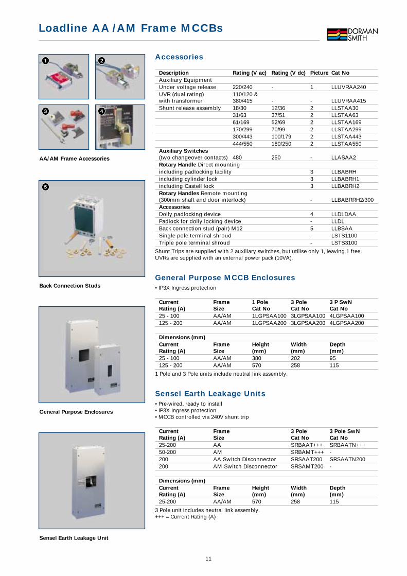
Accessories
Description Rating (V ac) Rating (V dc) Picture Cat No
Auxiliary EquipmentUnder voltage release 220/240 - 1 LLUVRAA240UVR (dual rating) 110/120 &with transformer 380/415 - - LLUVRAA415Shunt release assembly 18/30 12/36 2 LLSTAA30
31/63 37/51 2 LLSTAA6361/169 52/69 2 LLSTAA169170/299 70/99 2 LLSTAA299300/443 100/179 2 LLSTAA443444/550 180/250 2 LLSTAA550
Auxiliary Switches
(two changeover contacts) 480 250 - LLASAA2Rotary Handle Direct mountingincluding padlocking facility 3 LLBABRHincluding cylinder lock 3 LLBABRH1including Castell lock 3 LLBABRH2Rotary Handles Remote mounting(300mm shaft and door interlock) - LLBABRRH2/300Accessories
Dolly padlocking device 4 LLDLDAAPadlock for dolly locking device - LLDLBack connection stud (pair) M12 5 LLBSAASingle pole terminal shroud - LSTS1100Triple pole terminal shroud - LSTS3100
Shunt Trips are supplied with 2 auxiliary switches, but utilise only 1, leaving 1 free.UVRs are supplied with an external power pack (10VA).
General Purpose MCCB Enclosures• IP3X Ingress protection
Current Frame 1 Pole 3 Pole 3 P SwN
Rating (A) Size Cat No Cat No Cat No
25 - 100 AA/AM 1LGPSAA100 3LGPSAA100 4LGPSAA100125 - 200 AA/AM 1LGPSAA200 3LGPSAA200 4LGPSAA200
Dimensions (mm)
Current Frame Height Width Depth
Rating (A) Size (mm) (mm) (mm)
25 - 100 AA/AM 380 202 95125 - 200 AA/AM 570 258 115
1 Pole and 3 Pole units include neutral link assembly.
Sensel Earth Leakage Units• Pre-wired, ready to install• IP3X Ingress protection• MCCB controlled via 240V shunt trip
Current Frame 3 Pole 3 Pole SwN
Rating (A) Size Cat No Cat No
25-200 AA SRBAAT+++ SRBAATN+++50-200 AM SRBAMT+++ -200 AA Switch Disconnector SRSAAT200 SRSAATN200200 AM Switch Disconnector SRSAMT200 -
Dimensions (mm)
Current Frame Height Width Depth
Rating (A) Size (mm) (mm) (mm)
25-200 AA/AM 570 258 115
3 Pole unit includes neutral link assembly.+++ = Current Rating (A)
Loadline AA /AM Frame MCCBs
11
AA/AM Frame Accessories
Back Connection Studs
General Purpose Enclosures
Sensel Earth Leakage Unit
Loadline Y2 Frame MCCBs
12
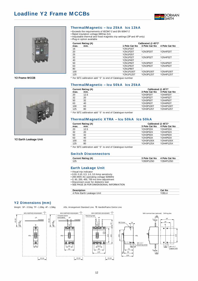
Y2 Frame MCCB
Y2 Earth Leakage Unit
Y2 Dimensions (mm)Weight: SP – 0.51kg TP – 1.30kg 4P – 1.58kg ASL: Arrangement Standard Line HL: Handle/Frame Centre Line
90
60
120
90
30
3P 4P
15
5
13
4
N
24
4 86
104
79
27 6
67
10
2
HLHL
ASL ASL
Interpole barrier(removable)
InsulatorInsulator
Mounting hole
M8 Screw
M4 x 0.7Mounting screw
45
.00
25
.00
25.00
MIN EARTHED BOUNDARY
30
1P
HL
ASL
45
.00
25
.00
25.00
MIN EARTHED BOUNDARY MIN EARTHED BOUNDARY
25.00
3P
4P
35
12
6
4
28
4
28
HL
Drilling planWith terminal bars (optional)
M4 x 0.7Tapped hole
Thermal/Magnetic – Icu 25kA Ics 13kA• Exceeds the requirements of IEC947-2 and EN 60947-2• Rated insulation voltage 690Vac (Ui)• Adjustable thermal and fixed magnetic trip settings (3P and 4P only)• Plug-in option available
Current Rating (A) Calibrated @ 45˚C*max. min. 1 Pole Cat No 3 Pole Cat No 4 Pole Cat No
16 Y2N1P16T - -20 Y2N1P20T Y2N3P20T Y2N4P20T25 Y2N1P25T - -32 Y2N1P32T Y2N3P32T Y2N4P32T40 Y2N1P40T - -50 Y2N1P50T Y2N3P50T Y2N4P50T63 Y2N1P63T Y2N3P63T Y2N4P63T80 Y2N1P80T - -100 Y2N1P100T Y2N3P100T Y2N4P100T125 Y2N1P125T Y2N3P125T Y2N4P125T
* For 50˚C calibration add “5” to end of Catalogue number
Thermal/Magnetic – Icu 50kA Ics 25kACurrent Rating (A) Calibrated @ 45˚C*max. min. 3 Pole Cat No 4 Pole Cat No
20 12.5 Y2H3P20T Y2H4P20T32 20 Y2H3P32T Y2H4P32T50 32 Y2H3P50T Y2H4P50T63 40 Y2H3P63T Y2H4P63T100 63 Y2H3P100T Y2H4P100T125 80 Y2H3P125T Y2H4P125T
* For 50˚C calibration add “5” to end of Catalogue number
Thermal/Magnetic XTRA – Icu 50kA Ics 50kACurrent Rating (A) Calibrated @ 45˚C*max. min. 3 Pole Cat No 4 Pole Cat No
20 12.5 Y2H3P20X Y2H4P20X32 20 Y2H3P32X Y2H4P32X50 32 Y2H3P50X Y2H4P50X63 40 Y2H3P63X Y2H4P63X100 63 Y2H3P100X Y2H4P100X125 80 Y2H3P125X Y2H4P125X
* For 50˚C calibration add “5” to end of Catalogue number
Switch DisconnectorsCurrent Rating (A) 3 Pole Cat No 4 Pole Cat No
125 Y2B3P125D Y2B4P125D
Earth Leakage Unit• Visual trip indicator• 0.03, 0.10, 0.3, 1.0, 3.0 Amp sensitivity• 200-440V AC operating voltage 50/60Hz• 0, 60, 200, 400, 700 ms time adjustment• Disconnect cover for dielectric test• SEE PAGE 26 FOR DIMENSIONAL INFORMATION
Description Cat No
4 Pole Earth Leakage Unit Y2ELU
Loadline Y2 Frame MCCBs
13
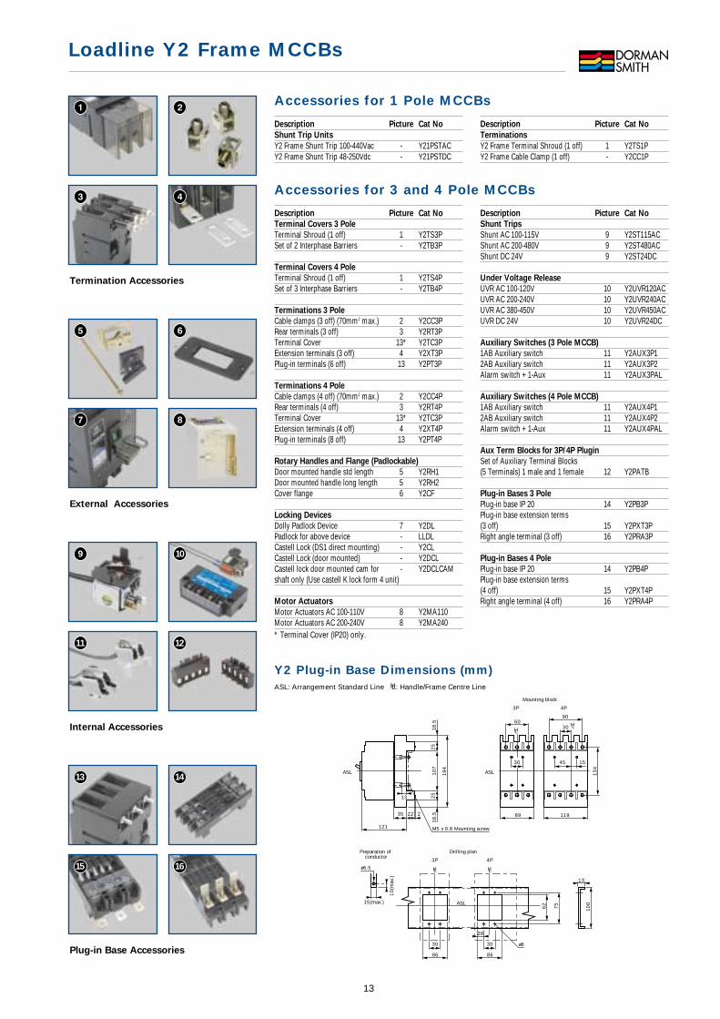
Termination Accessories
External Accessories
8
Internal Accessories
9 10
11 12
Plug-in Base Accessories
13 14
15 16
Description Picture Cat No
Terminal Covers 3 Pole
Terminal Shroud (1 off) 1 Y2TS3PSet of 2 Interphase Barriers - Y2TB3P
Terminal Covers 4 Pole
Terminal Shroud (1 off) 1 Y2TS4PSet of 3 Interphase Barriers - Y2TB4P
Terminations 3 Pole
Cable clamps (3 off) (70mm2 max.) 2 Y2CC3PRear terminals (3 off) 3 Y2RT3PTerminal Cover 13* Y2TC3PExtension terminals (3 off) 4 Y2XT3PPlug-in terminals (6 off) 13 Y2PT3P
Terminations 4 Pole
Cable clamps (4 off) (70mm2 max.) 2 Y2CC4PRear terminals (4 off) 3 Y2RT4PTerminal Cover 13* Y2TC3PExtension terminals (4 off) 4 Y2XT4PPlug-in terminals (8 off) 13 Y2PT4P
Rotary Handles and Flange (Padlockable)
Door mounted handle std length 5 Y2RH1Door mounted handle long length 5 Y2RH2Cover flange 6 Y2CF
Locking Devices
Dolly Padlock Device 7 Y2DLPadlock for above device - LLDLCastell Lock (DS1 direct mounting) - Y2CLCastell Lock (door mounted) - Y2DCLCastell lock door mounted cam for - Y2DCLCAMshaft only (Use castell K lock form 4 unit)
Motor Actuators
Motor Actuators AC 100-110V 8 Y2MA110Motor Actuators AC 200-240V 8 Y2MA240* Terminal Cover (IP20) only.
Description Picture Cat No
Shunt Trips
Shunt AC 100-115V 9 Y2ST115ACShunt AC 200-480V 9 Y2ST480ACShunt DC 24V 9 Y2ST24DC
Under Voltage Release
UVR AC 100-120V 10 Y2UVR120ACUVR AC 200-240V 10 Y2UVR240ACUVR AC 380-450V 10 Y2UVR450ACUVR DC 24V 10 Y2UVR24DC
Auxiliary Switches (3 Pole MCCB)
1AB Auxiliary switch 11 Y2AUX3P12AB Auxiliary switch 11 Y2AUX3P2Alarm switch + 1-Aux 11 Y2AUX3PAL
Auxiliary Switches (4 Pole MCCB)
1AB Auxiliary switch 11 Y2AUX4P12AB Auxiliary switch 11 Y2AUX4P2Alarm switch + 1-Aux 11 Y2AUX4PAL
Aux Term Blocks for 3P/4P Plugin
Set of Auxiliary Terminal Blocks(5 Terminals) 1 male and 1 female 12 Y2PATB
Plug-in Bases 3 Pole
Plug-in base IP 20 14 Y2PB3PPlug-in base extension terms(3 off) 15 Y2PXT3PRight angle terminal (3 off) 16 Y2PRA3P
Plug-in Bases 4 Pole
Plug-in base IP 20 14 Y2PB4PPlug-in base extension terms(4 off) 15 Y2PXT4PRight angle terminal (4 off) 16 Y2PRA4P
Accessories for 1 Pole MCCBs
Description Picture Cat No
Shunt Trip Units
Y2 Frame Shunt Trip 100-440Vac - Y21PSTACY2 Frame Shunt Trip 48-250Vdc - Y21PSTDC
Description Picture Cat No
Terminations
Y2 Frame Terminal Shroud (1 off) 1 Y2TS1PY2 Frame Cable Clamp (1 off) - Y2CC1P
Accessories for 3 and 4 Pole MCCBs
Y2 Plug-in Base Dimensions (mm)ASL: Arrangement Standard Line HL: Handle/Frame Centre Line
Drilling plan
ø6
3P
30
86
ASL
HL
4P
30
28
86
HL
75
62
Preparation of conductor
ø6.5
10
(max
.)
15(max.)
25
18
.5
13
4
154530
90
3060
18
.51
07
19
4
25
121
35 22 2 11989
4P3P
Mounting block
ASL ASL
M5 x 0.8 Mounting screw
HLHL
13
13
10
0
Thermal/Magnetic – Icu 25kA Ics 13kA• Exceeds the requirements of IEC947-2 and EN 60947-2• Rated insulation voltage 690Vac (Ui)• Adjustable thermal and fixed magnetic trip settings• Plug-in option available
Current Rating (A) Calibrated @ 45˚C*max. min. 3 Pole Cat No 4 Pole Cat No
160 100 Y3N3P160T Y3N4P160T250 160 Y3N3P250T Y3N4P250T
* For 50˚C calibration add “5” to end of Catalogue number
Thermal/Magnetic – Icu 50kA Ics 25kA
Current Rating (A) Calibrated @ 45˚C*max. min. 3 Pole Cat No 4 Pole Cat No
160 100 Y3H3P160T Y3H4P160T250 160 Y3H3P250T Y3H4P250T
* For 50˚C calibration add “5” to end of Catalogue number
Thermal/Magnetic – XTRA – Icu 50kA Ics 50kA• Exceeds the requirements of IEC947-2 and EN 60947-2• Rated insulation voltage 690Vac (Ui)• Adjustable thermal and fixed magnetic trip settings
Current Rating (A) Calibrated @ 45˚C*max. min. 3 Pole Cat No 4 Pole Cat No
160 100 Y3H3P160X Y3H4P160X* For 50˚C calibration add “5” to end of Catalogue number
Switch Disconnectors
Current Rating (A) 3 Pole Cat No 4 Pole Cat No
160 Y3B3P160D Y3B4P160D250 Y3B3P250D Y3B4P250D
Y3 Earth Leakage Units• Visual trip indicator• 0.03, 0.10, 0.3, 1.0, 3.0 Amp sensitivity• 200-440V AC operating voltage 50/60Hz• 0, 60, 200, 400, 700 ms time adjustment• Disconnect cover for dielectric test• SEE PAGE 26 FOR DIMENSIONAL INFORMATION
Description Cat No
Suitable for H range only Y3HELUSuitable for N range only Y3NELU
Loadline Y3 Frame MCCBs
14
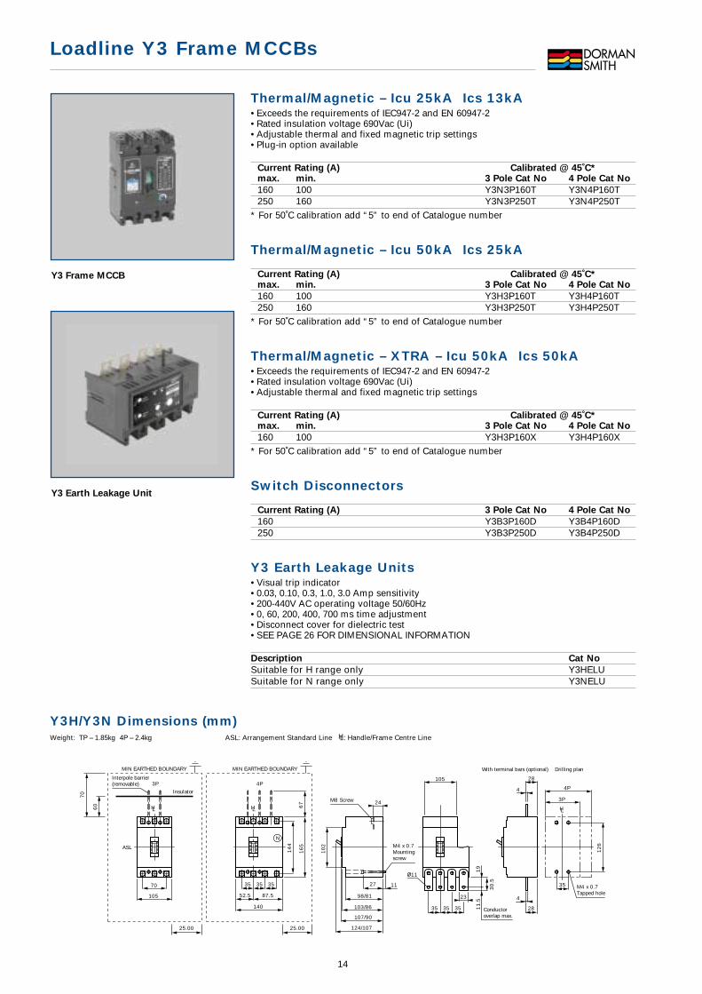
Y3 Frame MCCB
Y3 Earth Leakage Unit
Y3H/Y3N Dimensions (mm)Weight: TP – 1.85kg 4P – 2.4kg ASL: Arrangement Standard Line HL: Handle/Frame Centre Line
3P 4P
N
243P
4P
14
4
16
5
10
2
70
105
35 3535
52.5 87.5
140
67
35
12
6
105
11
35 35 35
23
19
11
.5
30
.5
4
28
4
28
11
107/90
103/86
98/81
27
124/107
HLHL HL
ASL
70
60
25.00
MIN EARTHED BOUNDARY
Interpole barrier(removable)
Conductoroverlap max.
Drilling planWith terminal bars (optional)
M4 x 0.7Tapped hole
Insulator
MIN EARTHED BOUNDARY
25.00
M8 Screw
M4 x 0.7Mountingscrew

Loadline Y3 Frame MCCBs
15
Termination Accessories
External Accessories
8
Internal Accessories
9 10
11 12
Plug-in Base Accessories
13 14
15 16
Y3H/Y3N Plug-in Base Dimensions (mm)ASL: Arrangement Standard Line HL: Handle/Frame Centre Line
Drilling plan
Mounting plate
13
10
0
62
3030
3P 4P
6
28
8686
75
HL HL
ASL
4P3P
Mounting block
Accessoryconnection block
M5 x 0.8Mounting screw
57
14
4
105 140
35 3535
18
18
18
0
121/104
HL HL
ASLASL
35 35
Accessories - Y3H only Accessories - Y3N onlyDescription Picture Cat No
Terminal Covers 3 Pole
Terminal Shroud (1 off) 1 Y3HTS3PSet of 2 Interphase Barriers - Y3HTB3PTerminal Covers 4 Pole
Terminal Shroud (1 off) 1 Y3HTS4PSet of 3 Interphase Barriers - Y3HTB4PTerminations 3 Pole
Cable clamps (3 off) (150mm2 max.) 2 Y3HCC3PTerminal Cover 13* Y3HTC3PPlug-in terminals (6 off) 13 Y3HPT3PTerminations 4 Pole
Cable clamps (4 off) (150mm2 max.) 2 Y3HCC4PTerminal Cover 13* Y3HTC4PPlug-in Terminals (8 off) 13 Y3HPT4PRotary Handles & Flange (Padlockable)
Door mounted handle std length 5 Y3HRH1Door mounted handle long length 5 Y3HRH2Castell Lock (DS1 direct mounting) - Y3HCLMotor Actuators
Motor Actuator AC 100-110V 8 Y3HMA110Motor Actuator AC 200-240V 8 Y3HMA240* Terminal Cover (IP20) Only
Description Picture Cat No
Terminal Covers 3 Pole
Terminal Shroud (1 off) 1 Y3NTS3PSet of 2 Interphase Barriers - Y2TB3PTerminal Covers 4 Pole
Terminal Shroud (1 off) 1 Y3NTS4PSet of 3 Interphase Barriers - Y2TB4PTerminations 3 Pole
Cable clamps (3 off) (150mm2 max.) 2 Y3NCC3PPlug-in terminals (6 off) 14 Y3NPT3PTerminal Cover 13* Y3NTC3PTerminations 4 Pole
Cable clamps (4 off) (150mm2 max.) 2 Y3NCC4PPlug-in Terminals (8 off) 14 Y3NPT4PTerminal Cover 13* Y3NTC4PRotary Handles & Flange (Padlockable)
Door mounted handle std length 5 Y3NRH1Door mounted handle long length 5 Y3NRH2Castell Lock (DS1 direct mounting) - Y3NCLMotor Actuators
Motor Actuator AC 100-110V 8 Y3NMA110Motor Actuator AC 200-240V 8 Y3NMA240
Description Picture Cat No
Terminations 3 Pole
Rear terminals (3 off) 3 Y3RT3PExtension terminals (3 off) 4 Y3XT3PTerminations 4 Pole
Rear terminals (4 off) 3 Y3RT4PExtension terminals (4 off) 4 Y3XT4PShunt Trips
Shunt AC 100-115V 9 Y3ST115ACShunt AC 200-480V 9 Y3ST480ACShunt DC 24V 9 Y3ST24DCUnder Voltage Release
UVR AC 100-120V 10 Y3UVR120ACUVR AC 200-240V 10 Y3UVR240ACUVR AC 380-450V 10 Y3UVR450ACUVR DC 24V 10 Y3UVR24DCAuxiliary Switches
1AB Auxiliary switch 11 Y3AUX12AB Auxiliary switch 11 Y3AUX2Alarm switch + 1-Aux 11 Y3AUXAL
Description Picture Cat No
Locking Devices
Dolly Padlock Device 7 Y3DLPadlock for above device - LLDLCastell Lock (door mounted) - Y2DCLCover flange 6 Y2CFCastell lock door mounted cam for - Y2DCLCAMshaft only (Use castell K lock form 4 unit)Aux Term Blocks for 3P/4P Plugin
Set of Aux Term Blocks for plug-in MCCB and base(5 Terminals) 1 male and 1 female 12 Y3PATBPlug-in Bases 3 Pole
Plug-in base IP 20 14 Y3PB3PPlug-in base extension terms (3 off) 15 Y3PXT3PRight angle terminal (3 off) 16 Y3PRA3PPlug-in Bases 4 Pole
Plug-in base IP 20 14 Y3PB4PPlug-in base extension terms (4 off) 15 Y3PXT4PRight angle terminal (4 off) 16 Y3PRA4P
Accessories - common to Y3H and Y3N
Thermal/Magnetic – Icu 50kA Ics 25kA• Exceeds the requirements of IEC947-2 and EN 60947-2• Rated insulation voltage 690Vac (Ui)• Adjustable thermal and adjustable magnetic trip settings• Plug-in option available
Current Rating (A) Calibrated @ 45˚C*
max. min. 3 Pole Cat No 4 Pole Cat No
250 125 Y5H3P250T Y5H4P250T400 250 Y5H3P400T Y5H4P400T
* For 50˚c calibration add “5” to end of catalogue number
Thermal/Magnetic – Icu 65kA Ics 50kA
Current Rating (A) Calibrated @ 45˚C*
max. min. 3 Pole Cat No 4 Pole Cat No
250 125 Y5J3P250T Y5J4P250T400 250 Y5J3P400T Y5J4P400T
* For 50˚c calibration add “5” to end of catalogue number
Electronic – Icu 50kA Ics 25kA• Exceeds the requirements of IEC947-2 and EN 60947-2• Rated insulation voltage 690Vac (Ui)• Microprocessor controlled fully adjustable trip settings• Plug-in option available
Current Rating (A)
max. min. 3 Pole Cat No 4 Pole Cat No
250 125 Y5H3P250E Y5H4P250E400 200 Y5H3P400E Y5H4P400E
Electronic – Icu 65kA Ics 50kA
Current Rating (A)
max. min. 3 Pole Cat No 4 Pole Cat No
250 125 Y5J3P250E Y5J4P250E400 200 Y5J3P400E Y5J4P400E
Switch Disconnectors
Current Rating (A) 3 Pole Cat No 4 Pole Cat No
400 Y5B3P400D Y5B4P400D
Loadline Y5 Frame MCCBs
16
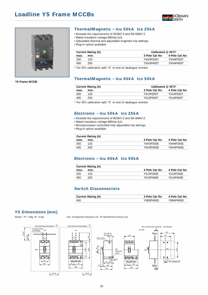
Y5 Frame MCCB
Y5 Dimensions (mm)Weight: TP – 4.8kg 4P – 6.2kg ASL: Arrangement Standard Line HL: Handle/Frame Centre Line
3P 4P
N
On side 31Off side 30 3P
4P
90
140
45 4545
70 115
185
45
21
4
8
39
8
38
22
8
26
01
10
28
14.7
69
145
1037.5
140
56
46
HLHL HL
ASL ASLASL
Interpole barrier(removable)
Drilling plan
On side
M6 Tapped hole
With terminal bars (optional)
70
.00
40
.00
30.00
MIN EARTHED BOUNDARY MIN EARTHED BOUNDARY
30.00
M10 Screw
M6Mountingscrew
45 4545
70 115
185
Loadline Y5 Frame MCCBs
17
Termination Accessories
External Accessories
8
Internal Accessories
9 10
11 12
Plug-in Base Accessories
13 14
15 16
AccessoriesDescription Picture Cat No
Terminal Covers 3 Pole
Terminal Shroud (1 off) 1 Y5TS3PSet of 2 Interphase Barriers - Y5TB3P
Terminal Covers 4 Pole
Terminal Shroud (1 off) 1 Y5TS4PSet of 3 Interphase Barriers - Y5TB4P
Terminations 3 Pole
Cable clamps (3 off) (240mm2 max)** 2 Y5CC3PRear terminals (3 off) 3 Y5RT3PTerminal Cover 13* Y5TC3PExtension terminals (3 off) 4 Y5XT3PPlug-in terminals (6 off) 13 Y5PT3P
Terminations 4 Pole
Cable clamps (4 off) (240mm2 max)** 2 Y5CC4PRear terminals (4 off) 3 Y5RT4PTerminal Cover 13* Y5TC4PExtension terminals (4 off) 4 Y5XT4PPlug-in terminals (8 off) 13 Y5PT4P
Rotary Handles & Flange (Padlockable)
Door mounted handle std length 5 Y5RH1Door mounted handle long length 5 Y5RH2Cover flange 6 Y5CF
Locking Devices
Dolly Padlock Device 7 Y5DLPadlock for above device - LLDLCastell Lock (DS1 direct mounting) - Y5CLCastell Lock (door mounted) - Y5DCLCastell lock door mounted cam for - Y5DCLCAMshaft only (Use castell K lock form 4 unit)* Terminal Cover (IP20) Only**(or 2x120mm2 max)
Description Picture Cat No
Motor Actuators
Motor Actuators AC 100-110V 8 Y5MA110Motor Actuators AC 200-240V 8 Y5MA240
Shunt Trips
Shunt AC 100-115V 9 Y5ST115ACShunt AC 200-480V 9 Y5ST480ACShunt DC 24V 9 Y5ST24DC
Under Voltage Release
UVR AC 100-120V 10 Y5UVR120ACUVR AC 200-240V 10 Y5UVR240ACUVR AC 380-450V 10 Y5UVR450ACUVR DC 24V 10 Y5UVR24DC
Auxiliary Switches
1AB Auxiliary switch 11 Y5AUX12AB Auxiliary switch 11 Y5AUX2Alarm switch + 1-Aux 11 Y5AUXAL
Aux Term Blocks for 3P/4P Plugin
Set of Auxiliary Terminal Blocks(5 Terminals) 1 male and 1 female 12 Y3PATB
Plug-in Bases 3 Pole
Plug-in base IP 20 14 Y5PB3PPlug-in base extension terms (3 off) 15 Y5PXT3PRight angle terminal (3 off) 16 Y5PRA3P
Plug-in Bases 4 Pole
Plug-in base IP 20 14 Y5PB4PPlug-in base extension terms (4 off) 15 Y5PXT4PRight angle terminal (4 off) 16 Y5PRA4P
Y5 Plug-in Base Dimensions (mm)ASL: Arrangement Standard Line HL: Handle/Frame Centre Line
Mounting angle
84
4P
Drilling plan
960
13
4
25
25
3P
ASL
HL
74119
4P
45 4545
13
420
54
20 2
82
11
.5
ASL
HL
11
.5
54
60
121
3P
Mounting block
M8 Mounting screw
Accessory connectionblock72
22
8
28
2
10
90
148
ASL ASL
HL

Thermal/Magnetic – Icu 50kA Ics 25kA• Exceeds the requirements of IEC947-2 and EN 60947-2• Rated insulation voltage 690Vac (Ui)• Adjustable thermal and adjustable magnetic trip settings• Plug-in option available
Current Rating (A) Calibrated @ 45˚C*max. min. 3 Pole Cat No 4 Pole Cat No
400 250 Y6H3P400T Y6H4P400T630 400 Y6H3P630T Y6H4P630T800 500 Y6H3P800T Y6H4P800T
* For 50˚c calibration add “5” to end of catalogue number
Thermal/Magnetic – Icu 85kA Ics 50 kACurrent Rating (A) Calibrated @ 45˚C*max. min. 3 Pole Cat No 4 Pole Cat No
400 250 Y6K3P400T Y6K4P400T630 400 Y6K3P630T Y6K4P630T800 500 Y6K3P800T Y6K4P800T
* For 50˚c calibration add “5” to end of catalogue number
Electronic – Icu 50kA Ics 25kACurrent Rating (A)max. min. 3 Pole Cat No 4 Pole Cat No
630 315 Y6H3P630E Y6H4P630E800 400 Y6H3P800E Y6H4P800E
Electronic – Icu 65kA Ics 50kACurrent Rating (A)max. min. 3 Pole Cat No 4 Pole Cat No
630 315 Y6J3P630E Y6J4P630E800 400 Y6J3P800E Y6J4P800E
Electronic Ground Fault Function – Icu 50kA Ics 25kACurrent Rating (A)max. min. 3 Pole Cat No 4 Pole Cat No
630 315 Y6H3P630EG† Y6H4P630EG800 400 Y6H3P800EG† Y6H4P800EG
† For Ground Fault protection on 4 wire systems see Ground Fault CT’s on page 20
Electronic Ground Fault Function – Icu 65kA Ics 50kACurrent Rating (A)max. min. 3 Pole Cat No 4 Pole Cat No
630 315 Y6J3P630EG† Y6J4P630EG800 400 Y6J3P800EG† Y6J4P800EG
† For Ground Fault protection on 4 wire systems see Ground Fault CT’s on page 20
Switch DisconnectorsCurrent Rating (A) 3 Pole Cat No 4 Pole Cat No
630 Y6B3P630D Y6B4P630D800 Y6B3P800D Y6B4P800D
NOTE: Terminals are supplied loose with MCCB.
Loadline Y6 Frame MCCBs
18
Y6 Frame MCCB
Y6 Dimensions (mm)Weight: 3P – 9.6kg 4P – 12.5kg ASL: Arrangement Standard Line HL: Handle/Frame Centre Line
1540
3P 4P
N
3P
4P
7.5
27
3
14
11
32
13
13
140
210 280
175105
70 7070
80
25
8
32
70
1032
6
36
10
2814
103
80.5 145
12
61
17
57
45
6
HL HL
HL
ASLASL ASL
8
80
Drilling plan
A
B
C
MIN EARTHED BOUNDARY MIN EARTHED BOUNDARY
C
Conductoroverlapmax.
Extension handle(removable)
M8Mountingscrew M8
Tappedhole
(Neutral:N)
A
Y6H,J
Y6K
70
80
40
50
30
40
B C

Loadline Y6 Frame MCCBs
19
Termination Accessories
External Accessories
Internal Accessories
8 9
10 11
Plug-in Base Accessories
12 13
14 15
AccessoriesDescription Picture Cat No
Terminal Covers 3 Pole
Terminal Shroud (1 off) 1 Y6TS3PSet of 2 Interphase Barriers - Y5TB3P
Terminal Covers 4 Pole
Terminal Shroud (1 off) 1 Y6TS4PSet of 3 Interphase Barriers - Y5TB4P
Terminations 3 Pole
Cable clamps (3 off) (240mm2)** 2 Y6CC3PRear terminals (3 off) 3 Y6RT3PTerminal Cover 12* Y6TC3PPlug-in terminals (6 off) 12 Y6PT3P
Terminations 4 Pole
Cable clamps (4 off) (240mm2)** 2 Y6CC4PRear terminals (4 off) 3 Y6RT4PTerminal Cover 12* Y6TC4PPlug-in Terminals (8 off) 12 Y6PT4P
Rotary Handles & Flange (Padlockable)
Door mounted handle std length 4 Y6RH1Door mounted handle long length 4 Y6RH2Cover flange 5 Y5CFHandle extension - Y6HE
Locking Devices
Dolly Padlock Device 6 Y6DLPadlock for above device - LLDLCastell Lock (DS1 direct mounting) - Y6CLCastell Lock (door mounted) - Y5DCLCastell lock door mounted cam for - Y5DCLCAMshaft only (Use castell K lock form 4 unit)* Terminal Cover (IP20) Only**(or 2x120mm2 max)**630A max
Description Picture Cat No
Motor Actuators
Motor Actuators AC 100-110V 7 Y6MA110Motor Actuators AC 200-240V 7 Y6MA240
Shunt Trips
Shunt AC 100-115V 8 Y6ST115ACShunt AC 200-480V 8 Y6ST480ACShunt DC 24V 8 Y6ST24DC
Under Voltage Release
UVR AC 100-120V 9 Y6UVR120ACUVR AC 200-240V 9 Y6UVR240ACUVR AC 380-450V 9 Y6UVR450ACUVR DC 24V 9 Y6UVR24DC
Auxiliary Switches
1AB Auxiliary switch 10 Y6AUX12AB Auxiliary switch 10 Y6AUX2Alarm switch + 1-Aux 10 Y6AUXAL
Aux Term Blocks for 3P/4P Plugin
Set of Auxiliary Terminal Blocks(5 Terminals) 1 male and 1 female 11 Y3PATB
Plug-in Bases 3 Pole
Plug-in base IP 20 13 Y6PB3PPlug-in base extension terms (3 off) 14 Y6PXT3PRight angle terminal (3 off) 15 Y6PRA3P
Plug-in Bases 4 Pole
Plug-in base IP 20 13 Y6PB4PPlug-in base extension terms (4 off) 14 Y6PXT4PRight angle terminal (4 off) 15 Y6PRA4P
Y6 Plug-in Base Dimensions (mm)ASL: Arrangement Standard Line HL: Handle/Frame Centre Line
Mounting angle
67
4P
Drilling plan
11
76
25
3P
HL
ASL
90
25
280
105121
4P3PM10 Mounting screw
Mounting block
Accessory connection block
62 45
15
61
47
12
61
17 90
70
175
62
18
18
62
67
76
30
3
210
140
ASL ASLASL
HL HL
70 70
90
Electronic – Icu 65kA Ics 49kA• Exceeds the requirements of IEC947-2 and EN 60947-2• Rated insulation voltage 690Vac (Ui)• Microprocessor controlled fully adjustable trip settings• Plug-in option available
Current Rating (A)max. min. 3 Pole Cat No 4 Pole Cat No1000 500 Y7J3P1000E Y7J4P1000E1250 630 Y7J3P1250E Y7J4P1250E
Electronic Ground Fault Function – Icu 65kA Ics 49kA
Current Rating (A)max. min. 3 Pole Cat No 4 Pole Cat No1000 500 Y7J3P1000EG† Y7J4P1000EG1250 630 Y7J3P1250EG† Y7J4P1250EG
† For Ground Fault protection on 4 wire systems see Ground Fault CT’s below
Switch Disconnectors
Current Rating (A) 3 Pole Cat No 4 Pole Cat No1250A Y7B3P1250D Y7B4P1250D
Ground Fault Current Transformers Y6 and Y7These units are required when using a 3 Pole device on a 4 wire system.
Y Frame MCCB CT Current Rating Current TransformerPrimary Secondary Catalogue Number
Y6J3P630EG 630A 50mA Y6GF63CTY6J3P800EG 800A 50mA Y6GF80CTY7J3P1000EG 1000A 50mA Y7GF10CTY7J3P1250EG 1250A 50mA Y7GF12CTY8K3P1600EG 1600A 50mA Y8GF16CT
External Dimensions (mm)CT Type A B C D E F H CH M N Weight (kg)Y6GF 105 100 40 8 50 75 110 57 50 20 1.2Y7GF/Y8GF 140 110 50 10 80 85 145 75 85 35 2.2
E
A
F
C
CH
H
B
M
CT mounting hole Secondary side terminal M4
External neutral sensor
Hole for primaryside conductor
CT base
N
D
Loadline Y7 Frame MCCBs
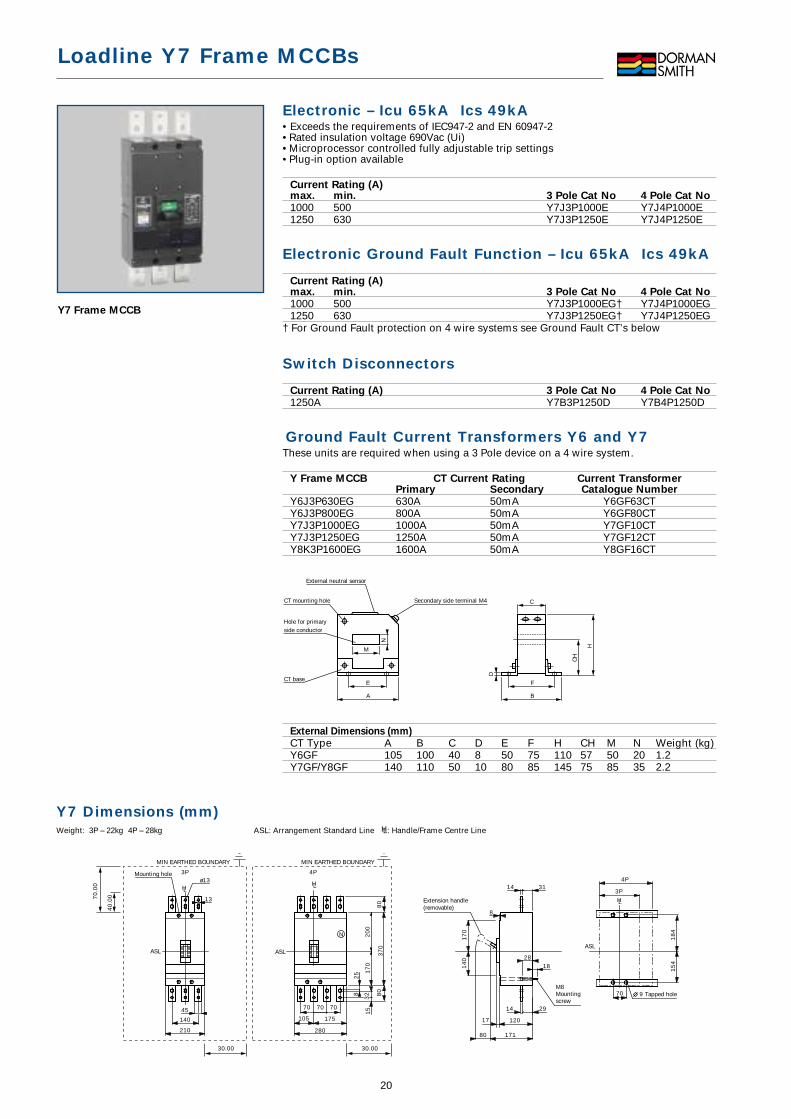
Y7 Frame MCCB
20
Y7 Dimensions (mm)Weight: 3P – 22kg 4P – 28kg ASL: Arrangement Standard Line HL: Handle/Frame Centre Line
1545
3P 4P
N
3P
4Pø13
13
140
210 280
175105
7070 70
25
8
32 70
28
80
17
02
00
37
0
8
17
18
17
01
40
80
15
4
9 Tapped hole
171
120
14 29
14 31
18
4
Extension handle(removable)
M8Mountingscrew
Mounting hole
ASL
HL
ASLASL
HLHL
80
70
.00
40
.00
30.00
MIN EARTHED BOUNDARY MIN EARTHED BOUNDARY
30.00
Loadline Y7 Frame MCCBs
Termination Accessories
External Accessories
Internal Accessories
8 9
10 11
Plug-in Base Accessories
12 13
21
AccessoriesDescription Picture Cat No
Terminal Covers 3 Pole
Terminal Shroud (1 off) 1 Y7TS3PSet of 2 Interphase Barriers - Y5TB3P
Terminal Covers 4 Pole
Terminal Shroud (1 off) 1 Y7TS4PSet of 3 Interphase Barriers - Y5TB4P
Terminations 3 Pole
Rear terminals (3 off) 3 Y7RT3PPlug-in terminals (6 off) 12 Y7PT3P
Terminations 4 Pole
Rear terminals (4 off) 3 Y7RT4PPlug-in Terminals (8 off) 12 Y7PT4P
Rotary Handles & Flange (Padlockable)
Door mounted handle std length 4 Y7RH1Door mounted handle long length 4 Y7RH2Cover flange 4 Y7CFHandle extension Y6HE
Locking Devices
Dolly Padlock Device 6 Y7DLPadlock for above device - LLDLCastell Lock (DS1 direct mounting) - Y7CLCastell Lock (door mounted) - Y5DCLCastell lock door mounted cam for - Y5DCLCAMshaft only (Use castell K lock form 4 unit)
Motor Actuators
Motor Actuators AC 100-110V 7 Y7MA110Motor Actuators AC 200-240V 7 Y7MA240
Description Picture Cat No
Shunt Trips
Shunt AC 100-115V 8 Y7ST115ACShunt AC 200-480V 8 Y7ST480ACShunt DC 24V 8 Y7ST24DC
Under Voltage Release
UVR AC 100-120V 9 Y7UVR120ACUVR AC 200-240V 9 Y7UVR240ACUVR AC 380-450V 9 Y7UVR450ACUVR DC 24V 9 Y7UVR24DC
Auxiliary Switches 3 Pole MCCB
1AB Auxiliary switch 10 Y7AUX3P12AB Auxiliary switch 10 Y7AUX3P2Alarm switch + 1-Aux 10 Y7AUX3PAL
Auxiliary Switches 4 Pole MCCB
1AB Auxiliary switch 10 Y7AUX4P12AB Auxiliary switch 10 Y7AUX4P2Alarm switch + 1-Aux 10 Y7AUX4PAL
Aux Term Blocks for 3P/4P Plugin
Set of Auxiliary Terminal Blocks(5 Terminals) 1 male and 1 female 11 Y3PATB
Plug-in Bases 3 Pole
Plug-in base IP 20 13 Y7PB3P
Plug-in Bases 4 Pole
Plug-in base IP 20 13 Y7PB4P
Y7 Plug-in Base Dimensions (mm)ASL: Arrangement Standard Line HL: Handle/Frame Centre Line
280
140 707070210
64
4P
94
25
3P
HL
Mounting angle
ASL
175 105
21
58
26
21
58
64
94
90
ASL
90
19
91
69
11
90
4PHLHL
3P
26
21
58
26
21
58
64
94
19
91
69
26
25
70 70 7062 85
15
3P
4P
8 30
32
Mounting angle
M10 Mounting screw
138
Conductor overlap max.
18
21
15
11
41
44
Control circuit terminal
13
45
14
7
15
13
8 30
32
ASL
HL
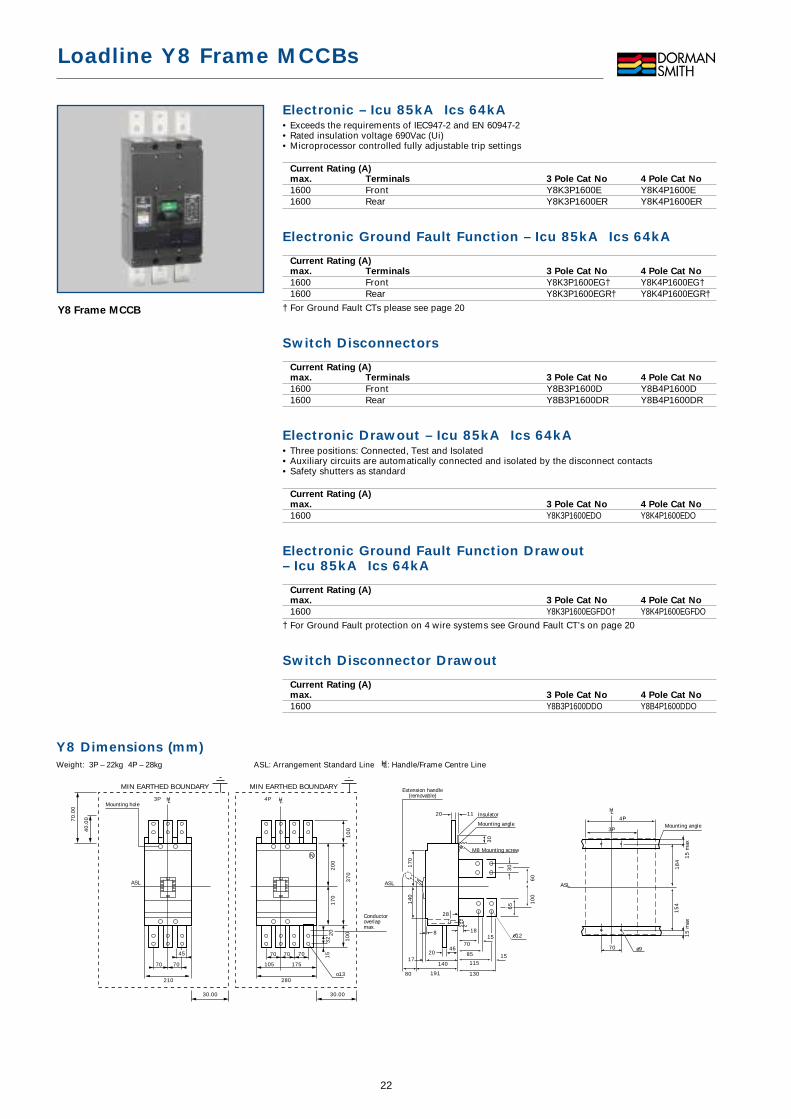
Electronic – Icu 85kA Ics 64kA• Exceeds the requirements of IEC947-2 and EN 60947-2• Rated insulation voltage 690Vac (Ui)• Microprocessor controlled fully adjustable trip settings
Current Rating (A)max. Terminals 3 Pole Cat No 4 Pole Cat No
1600 Front Y8K3P1600E Y8K4P1600E1600 Rear Y8K3P1600ER Y8K4P1600ER
Electronic Ground Fault Function – Icu 85kA Ics 64kA
Current Rating (A)max. Terminals 3 Pole Cat No 4 Pole Cat No
1600 Front Y8K3P1600EG† Y8K4P1600EG†1600 Rear Y8K3P1600EGR† Y8K4P1600EGR†
† For Ground Fault CTs please see page 20
Switch Disconnectors
Current Rating (A)max. Terminals 3 Pole Cat No 4 Pole Cat No
1600 Front Y8B3P1600D Y8B4P1600D1600 Rear Y8B3P1600DR Y8B4P1600DR
Electronic Drawout – Icu 85kA Ics 64kA• Three positions: Connected, Test and Isolated• Auxiliary circuits are automatically connected and isolated by the disconnect contacts• Safety shutters as standard
Current Rating (A)max. 3 Pole Cat No 4 Pole Cat No
1600 Y8K3P1600EDO Y8K4P1600EDO
Electronic Ground Fault Function Drawout– Icu 85kA Ics 64kA
Current Rating (A)max. 3 Pole Cat No 4 Pole Cat No
1600 Y8K3P1600EGFDO† Y8K4P1600EGFDO† For Ground Fault protection on 4 wire systems see Ground Fault CT’s on page 20
Switch Disconnector Drawout
Current Rating (A)max. 3 Pole Cat No 4 Pole Cat No
1600 Y8B3P1600DDO Y8B4P1600DDO
Loadline Y8 Frame MCCBs
Y8 Frame MCCB
22
Y8 Dimensions (mm)Weight: 3P – 22kg 4P – 28kg ASL: Arrangement Standard Line HL: Handle/Frame Centre Line
Mounting hole
Conductoroverlapmax.
o13
Extension handle(removable)
Insulator
Mounting angle
M8 Mounting screw
Mounting angle
ø970
4P
3P
HL
18
4
15
max
15
max
15
4
17
01
40
37
01
00
10
0
30
188
2017
80 191
20 11
28
46
140
70
105
280
175
70 70
210
70 70
45
20
32
15
20
01
70
4P3P HL HL
ASLASL ASL
N
o12
30
65 1
00
60
70
85
115
130
15
15
MIN EARTHED BOUNDARY MIN EARTHED BOUNDARY
70
.00
40
.00
30.00 30.00
Loadline Y8 Frame MCCBs
Accessories
Accessories
8
23
Accessories
Description Picture Cat No
Terminal Covers 3 Pole
Terminal Shroud (1 off) 1 Y7TS3P
Set of 2 Interphase Barriers - Y5TB3P
Terminal Covers 4 Pole
Terminal Shroud (1 off) 1 Y7TS4P
Set of 3 Interphase Barriers - Y5TB4P
Terminations 4 Pole
Rear terminals (4 off) - Y7RT4P
Plug-in Terminals (8 off) - Y7PT4P
Rotary Handles & Flange (Padlockable)
Door mounted handle std length 2 Y7RH1
Door mounted handle long length 2 Y7RH2
Cover flange 2 Y7CF
Handle extension Y6HE
Locking Devices
Dolly Padlock Device 4 Y7DL
Padlock for above device - LLDL
Castell Lock (DS1 direct mounting) - Y7CL
Castell Lock (door mounted) - Y5DCL
Castell lock door mounted cam for - Y5DCLCAMshaft only (Use castell K lock form 4 unit)
Description Picture Cat No
Motor Actuators
Motor Actuators AC 100-110V 5 Y7MA110
Motor Actuators AC 200-240V 5 Y7MA240
Shunt Trips
Shunt AC 100-115V 6 Y7ST115AC
Shunt AC 200-480V 6 Y7ST480AC
Shunt DC 24V 6 Y7ST24DC
Under Voltage Release
UVR AC 100-120V 7 Y7UVR120AC
UVR AC 200-240V 7 Y7UVR240AC
UVR AC 380-450V 7 Y7UVR450AC
UVR DC 24V 7 Y7UVR24DC
Auxiliary Switches 3 Pole MCCB
1AB Auxiliary switch 8 Y7AUX3P1
2AB Auxiliary switch 8 Y7AUX3P2
Alarm switch + 1-Aux 8 Y7AUX3PAL
Auxiliary Switches 4 Pole MCCB
1AB Auxiliary switch 8 Y7AUX4P1
2AB Auxiliary switch 8 Y7AUX4P2
Alarm switch + 1-Aux 8 Y7AUX4PAL
Y8 Draw-out Dimensions (mm)ASL: Arrangement Standard Line HL: Handle/Frame Centre Line
Accessory connectionblock
Breakerfixing screw
Mounting hole
10
54
20
370 (max.)
220150
300 (max.)
220
3P 4P
HL HL
20
02
20
ASL
Draw-out handle(removable)
Ø12 Mounting hole
Conductor overlap max.
Conductoroverlap max.
Mounting angle
395 (Draw-out)
325 (Disconnected)
295 (Test)
265 (Connected)
90o
215
170 (4P)
17
0
20
12
025
25
70
20
60
10
0
75
50
707070
4P
20
100 (4P)
19
020
225 o123P
ASL
ASL
282
316
396 (connected)526 (drawout)
HL182.5112.5
HL
200 (3P)
4P
3P

The steady state current produced by a generator under a fault condition can be as lowas 3 times the full load current. The Loadline Generator Type MCCBs have beendeveloped to have a magnetic setting calibrated to trip quickly on low generator faults.
Y2 Frame Generator Type MCCBs –Icu 25kA Ics 13kA• Exceeds the requirements of IEC947-2 and EN 60947-2• Rated insulation voltage 690Vac (Ui)• Adjustable thermal and fixed magnetic trip settings• Plug-in unit available• SEE PAGES 12 - 13 FOR DIMENSIONS AND ACCESSORIES
Current Rating (A) Magnetic X In Calibrated @ 45˚C*
max. min. Trip Current 3 Pole Cat No 4 Pole Cat No
20 12.5 95 4.75 Y2N3P20G Y2N4P20G32 20 120 3.75 Y2N3P32G Y2N4P32G50 32 150 3 Y2N3P50G Y2N4P50G63 40 200 3 Y2N3P63G Y2N4P63G100 63 300 3 Y2N3P100G Y2N4P100G125 80 375 3 Y2N3P125G Y2N4P125G
* For 50˚c calibration add “5” to end of catalogue number
Y3 Frame Generator Type MCCBs –Icu 25kA Ics 13kA• Exceeds the requirements of IEC947-2 and EN 60947-2• Rated insulation voltage 690Vac (Ui)• Adjustable thermal and fixed magnetic trip settings• Plug-in unit available• SEE PAGES 14 - 15 FOR DIMENSIONS AND ACCESSORIES
Current Rating (A) Magnetic X In Calibrated @ 45˚C*
max. min. Trip Current 3 Pole Cat No 4 Pole Cat No
160 100 400 2.5 Y3N3P160G Y3N4P160G250 160 625 2.5 Y3N3P250G Y3N4P250G
* For 50˚c calibration add “5” to end of catalogue number
Y5 Frame Generator Type MCCBs – Icu 50kA Ics 25kA• Exceeds the requirements of IEC947-2 and EN 60947-2• Rated insulation voltage 690Vac (Ui)• Adjustable thermal and adjustable magnetic trip settings• Plug-in unit available• SEE PAGES 16 - 17 FOR DIMENSIONS AND ACCESSORIES
Current Rating (A) Mag Trip Current X In Calibrated @ 45˚C*
max. min. Low High Low High 3 Pole Cat No 4 Pole Cat No
250 160 620 1250 2.5 5 Y5H3P250G Y5H4P250G400 250 1000 2000 2.5 5 Y5H3P400G Y5H4P400G
* For 50˚c calibration add “5” to end of catalogue number
Y6 Frame Generator Type MCCBs – Icu 50kA Ics 25kA• Exceeds the requirements of IEC947-2 and EN 60947-2• Rated insulation voltage 690Vac (Ui)• Adjustable thermal and adjustable magnetic trip settings• Plug-in unit available• SEE PAGES 18 - 19 FOR DIMENSIONS AND ACCESSORIES
Current Rating (A) Mag Trip Current X In Calibrated @ 45˚C*
max. min. Low High Low High 3 Pole Cat No 4 Pole Cat No
400 250 1000 2000 2.5 5 Y6H3P400G Y6H4P400G630 400 1600 3150 2.5 5 Y6H3P630G Y6H4P630G800 500 2000 4000 2.5 5 Y6H3P800G Y6H4P800G
* For 50˚c calibration add “5” to end of catalogue number
Loadline Generator Type MCCBs
Y2 Frame MCCBs
Y3 Frame MCCBs
Y5 Frame MCCBs
Y6 Frame MCCBs
24
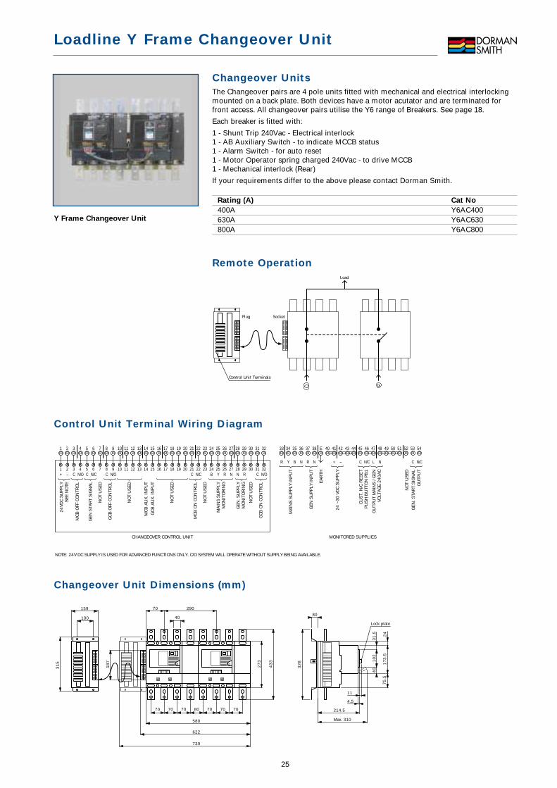
Changeover UnitsThe Changeover pairs are 4 pole units fitted with mechanical and electrical interlockingmounted on a back plate. Both devices have a motor acutator and are terminated forfront access. All changeover pairs utilise the Y6 range of Breakers. See page 18.
Each breaker is fitted with:
1 - Shunt Trip 240Vac - Electrical interlock1 - AB Auxiliary Switch - to indicate MCCB status1 - Alarm Switch - for auto reset1 - Motor Operator spring charged 240Vac - to drive MCCB1 - Mechanical interlock (Rear)
If your requirements differ to the above please contact Dorman Smith.
Rating (A) Cat No
400A Y6AC400630A Y6AC630800A Y6AC800
Remote Operation
SocketPlug
Load
G
Control Unit Terminals
Loadline Y Frame Changeover Unit
Y Frame Changeover Unit
25
Control Unit Terminal Wiring Diagram
Changeover Unit Dimensions (mm)
70
70159
100
290
580
622
739
40
70 80 70 70 214.5
4.5
Lock plate
11
Max. 310
43
3
27
3 17
3.5
75
.5
32
8 10
24
03
1.5 24
31
5
7070
80
18
7
1 2 3 4 5 6 7 8 9 10 11 12 13 14 15 16 17 18 19 20 21 22 23 24 25 26 27 28 29 30 31 32
1
24VD
C SU
PPLY
SEE
NO
TE
NOTE: 24V DC SUPPLY IS USED FOR ADVANCED FUNCTIONS ONLY. C/O SYSTEM WILL OPERATE WITHOUT SUPPLY BEING AVAILABLE.
MCB
OFF
CO
NTR
OL
2+ –
3 4 5 6 7 8 9 10 11 12 13 14 15 16
CHANGEOVER CONTROL UNIT MONITORED SUPPLIES
17 18 19 20 21 22 23 24 25 26 27 28 29 30 31 32
33 34 35 36
C N/O
GEN
STA
RT
SIG
NAL
NO
T U
SED
NO
T U
SED
NO
T U
SED
C N/C
MCB
ON
CO
NTR
OL
C B NRYN/C
GCB
ON
CO
NTR
OL
C N/O
MAI
NS
SUPP
LY IN
PUT
R Y NB
EAR
TH
NO
T U
SED
OU
TPU
T M
AIN
S / G
ENVO
LTAG
E 24
0AC
L N
24 ~
30 V
DC
SUPP
LY
+ –
CUST
. N/C
RES
ETPU
SH B
UTT
ON
PB
1
C N/C
GEN
. STA
RT
SIG
NAL
OU
TPU
T
C N/C
GEN
SU
PPLY
INPU
T
R N
GEN
. SU
PPLY
MO
NIT
OR
ING
N R
GCB
OFF
CO
NTR
OL
NO
T U
SED
GCB
AU
X. IN
PUT
MCB
AU
X. IN
PUT
C N/O
NO
T U
SED
MAI
NS
SUPP
LYM
ON
ITO
RIN
G
37 38 E 40 41 42 43 44 45 46 47 48 49 50 51 52 53 54

Plug-in Base Operation• IP-20 degree of protection.• Safety Trip (Trip first, plug-in mechanism)
The breaker will trip automatically, if it is withdrawn while still in the ‘ON’ position. It isnot possible to “plug-in” the breaker when it is in the ‘ON’ position.
Torque Settings for Cable TerminationFrame Size No. Cable Size Torque N/m Torque N/m
of Poles (mm2) Cable Clamp
Y2 3 70mm2 5.64 2.35 ~ 3.434
Y3 3 150mm2 28.22 6.86 ~ 9.314
Y5 3 240mm2 or 28.22 6.86 ~ 9.314 2x 120mm2
Y6 3 240mm2 or 28.22 6.86 ~ 9.314 2x 120mm2
Y7/8 3 240mm2 or 28.22 6.86 ~ 9.314 2x 120mm2
Plug-in Base Assembly Components
Y2 and Y3 Earth Leakage Units• Visual trip indicator• 0.03, 0.10, 0.3, 1.0, 3.0 Amp sensitivity• 200-440V AC operating voltage 50/60Hz• 0, 60, 200, 400, 700 Ms time adjustment• Disconnect cover for dielectric test
Description Cat No
Y2 Frame Y2ELUY3H Frame Y3HELUY3N Frame Y3NELU
Dimensions (mm)Y2 Frame Size Y3 N&H Frame Size
N
165
114
86
120
98
103
50
4
N
155
80
86
120
79
50
86 4
Conductor
TerminalsPlug-in mounting blockMounting angle(not supplied)
WarningSecure the conductor with the correct nut and washer to ensure full contact of conductor with terminal on the plug-in mounting block, so that the steel stud bolt is not used as the current path
Auxiliary circuit terminalsmounted onbreaker body.
Terminalleads forinternallymountedaccessories
Switchboard sidecontrol lead
Auxiliary circuit terminalsmounted on the plug-in mounting block.
Conductor (not supplied)
Loadline Y Frame Plug-in Bases
Plug-in Base Connections
Plug-in Base Assembly
Y Frame Earth Leakage Unit
26
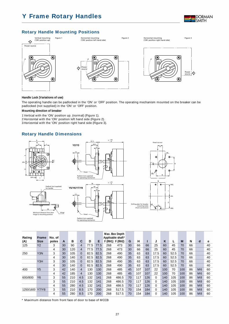
Rotary Handle Mounting Positions
Handle Lock (Variations of use)
The operating handle can be padlocked in the ‘ON’ or ‘OFF’ position. The operating mechanism mounted on the breaker can bepadlocked (not supplied) in the ‘ON’ or ‘OFF’ position.
Mounting direction of breaker
1 Vertical with the ‘ON’ position up. (normal) (Figure 1).2 Horizontal with the ‘ON’ position left hand side (Figure 2).3 Horizontal with the ‘ON’ position right hand side (Figure 3).
Rotary Handle Dimensions+10 – 0
øe
C
ASL
MSL
MSL
ø6
HL
Panel cut-out
Drilling plan for breakermounting holes
(front connection)
14
Panel
Padlock (not supplied)for operating mechanism
Hinge
Padlock (not supplied)for handle
Minimum distance from doorhinge to mounting position
12 A
G
12
IH
N
ød
M
61.5
39.5
F
+15– 0
15
Panel
Padlock (not supplied)for operating mechanism
13
78
54
F
I
ASLC
ON-side
OFF-side
HL
K
JA
B
ED
L
HL
N
Y2/Y3
Y5/Y6/Y7/Y8
OOO
Power source
Vertical mounting('ON' position up)
Figure 1
Powersource
Horizontal mounting('ON' position left hand side)
Figure 2
Powersource
Figure 3Horizontal mounting('ON' position right hand side)
Y Frame Rotary Handles
27
* Maximum distance from front face of door to base of MCCB
Rating
(A)
125
250
400
600/800
1250/1600
Frame
Size
Y2
Y3N
Y3H
Y5
Y6
Y7/Y8
No. of
poles
3434343433434
A
30303030303042425555555555
B
90120105140105140140185210210280210280
C
44000044
4.54.54.58.58.5
D
77.577.582.582.582.582.5130130132132132170170
E
77.5 77.5 82.5 82.582.582.5130130141141141200200
Max. Box Depth
Applicable shaft*
F (RH1) F (RH2)
268 473268 473268 490268 490268 490268 490268 485268 485268 486.5268 486.5268 486.5268 517.5268 517.5
G
30303535353545457070707070
H
666663636363107107117117117154154
I
666663636363107107126126126184184
J
2525
17.517.517.517.5222200000
K
606060606060100100140140140140140
L
4545
52.552.552.552.57070105105105105105
M
707070707070100100100100100100100
N
66666666666686868686868686
d
M6M6M8M8M8M8M8
e
40404040404060606060606060
28
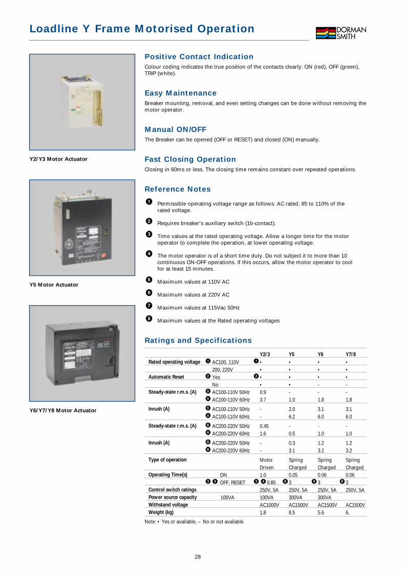
Y2/Y3 Motor Actuator
Loadline Y Frame Motorised Operation
Positive Contact IndicationColour coding indicates the true position of the contacts clearly: ON (red), OFF (green),TRIP (white).
Easy MaintenanceBreaker mounting, removal, and even setting changes can be done without removing themotor operator.
Manual ON/OFFThe Breaker can be opened (OFF or RESET) and closed (ON) manually.
Fast Closing OperationClosing in 60ms or less. The closing time remains constant over repeated operations.
Reference Notes
Permissible operating voltage range as follows: AC rated, 85 to 110% of the rated voltage.
Requires breaker’s auxiliary switch (1b-contact).
Time values at the rated operating voltage. Allow a longer time for the motoroperator to complete the operation, at lower operating voltage.
The motor operator is of a short time duty. Do not subject it to more than 10continuous ON-OFF operations. If this occurs, allow the motor operator to cool for at least 15 minutes.
Maximum values at 110V AC
Maximum values at 220V AC
Maximum values at 115Vac 50Hz
Maximum values at the Rated operating voltages
Ratings and Specifications
Y2/3 Y5 Y6 Y7/8
Rated operating voltage AC100, 110V • • • •200, 220V • • • •
Automatic Reset Yes • • • •No • • - -
Steady-state r.m.s. (A) AC100-110V 50Hz 0.9 - - -AC100-110V 60Hz 3.7 1.0 1.8 1.8
Inrush (A) AC100-110V 50Hz - 2.0 3.1 3.1AC100-110V 60Hz - 6.2 6.0 6.0
Steady-state r.m.s. (A) AC200-220V 50Hz 0.45 - - -AC200-220V 60Hz 1.6 0.5 1.0 1.0
Inrush (A) AC200-220V 50Hz - 0.3 1.2 1.2AC200-220V 60Hz - 3.1 3.2 3.2
Type of operation Motor Spring Spring SpringDriven Charged Charged Charged
Operating Time(s) ON 1.0 0.05 0.06 0.06OFF, RESET 0.85 3 3 3
Control switch ratings 250V, 5A 250V, 5A 250V, 5A 250V, 5APower source capacity 100VA 100VA 300VA 300VAWithstand voltage AC1000V AC1500V AC1500V AC1500VWeight (kg) 1.8 8.5 5.6 6.
Note: • Yes or available, – No or not available
888
8
Y5 Motor Actuator
Y6/Y7/Y8 Motor Actuator
29
Loadline Y Frame Motorised Operation
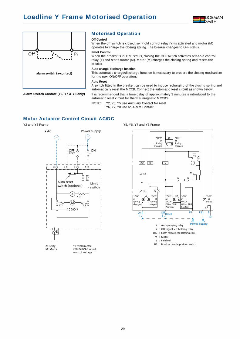
Motorised OperationOff Control
When the off switch is closed, self-hold control relay (Y) is activated and motor (M)operates to charge the closing spring. The breaker changes to OFF status.
Reset Control
When the breaker is in TRIP status, closing the OFF switch activates self-hold controlrelay (Y) and starts motor (M). Motor (M) charges the closing spring and resets thebreaker.
Auto charge/discharge function
This automatic charge/discharge function is necessary to prepare the closing mechanismfor the next ON/OFF operation.
Auto Reset
A switch fitted in the breaker, can be used to induce recharging of the closing spring andautomatically reset the MCCB. Connect the automatic reset circuit as shown below.
It is recommended that a time delay of approximately 3 minutes is introduced to theautomatic reset circuit for thermal magnetic MCCB's.
NOTE: Y2, Y3, Y5 use Auxiliary Contact for resetY6, Y7, Y8 use an Alarm Contact
P1Off
alarm switch (a-contact)
Alarm Switch Contact (Y6, Y7 & Y8 only)
Y5, Y6, Y7 and Y8 Frame
Motor Actuator Control Circuit AC/DCY2 and Y3 Frame
D C B A
X 2 X 1
– +
X
M
• AC Power supply
ONOFF(RESET)
* R
* Fitted in case200-220VAC ratedcontrol voltage
Auto resetswitch (optional)
Limitswitch
E
X: RelayM: Motor
Yc
"OFF"at
locked
EP2P1ResetOffE
OnE
__+
"ON"atMCCBON or TRIPPosition
"OFF"atMCCBON or TRIPPosition
"OFF"at
Springcharged
HSLS"ON"atSpringcharged
LRC X
Yc
YaYa
Xb
Xb Xa
Y
"OFF"at
Springcharged
"ON"atSpringcharged
LS
Power SupplyX
Y
LRC
M
HS
: Anti-pumping relay
: OFF signal self-holding relay
: Latch release coil (closing coil)
: Motor
: Field coil
: Breaker handle position switch
+

Auxiliary and Alarm Switch RatingsApplicable breakers Switch type Y2/Y3 Y5/Y6/Y7/Y8
30
Y Frame Accessory Information
Internally Mounted Accessories
Accessory
Combination
Y3
Frame
Y5
Frame
Y6
Frame
Alarm SwitchAuxiliary Switch
Undervoltage Release
Undervoltage Release
Alarm SwitchUndervoltage Release
Undervoltage Release
Alarm SwitchAuxiliary Switch
Shunt Trip
Alarm SwitchShunt Trip
Alarm SwitchShunt Trip
Shunt Trip
Auxiliary Switch
Auxiliary Switch
10
3
4
5
6
7
8
9
2
1
Auxiliary SwitchAlarm Switch
Y7/Y8
Frame
Y2
Frame
Operation of Auxiliary Switch and Alarm Switch
UVR Power ConsumptionPower supply (vA)*Y2/Y3 Y5/Y6/Y7/Y8
Voltage
100-120V AC 5VA 5VA200-240V AC 5VA 5VA300-450V AC 5VA 5VA
Exciting coil current24V DC 18.2 mA 22.7 mA
*Power Supply burden with UVR power pack
•Auxiliary
Switch type Breaker ‘ON’ Breaker ‘OFF’ Breaker ‘TRIP’
*Alarm
Switch type
*b1 *a1
*c1
Breaker ‘ON’
*b1 *a1
*c1
Breaker ‘OFF’
*b1 *a1
*c1
Breaker ‘TRIP’
AC Voltage (V)
Current (A)
DC Voltage (V)
Current (A)
Resistive loadLamp loadInductive loadMotor load
Resistive loadLamp loadInductive loadMotor load
480 2500.4 30.05 0.30.25 20.1 0.5250 1250.2 0.40.03 0.050.03 0.050.03 0.05
125 480 250 1253 3 5 5
0.5 0.3 1.5 22 2 5 5
0.7 0.4 2 330 250 125 303 0.3 0.6 51 0.05 0.1 32 0.3 0.6 42 0.05 0.1 3
31
Loadline Y Frame Application Data
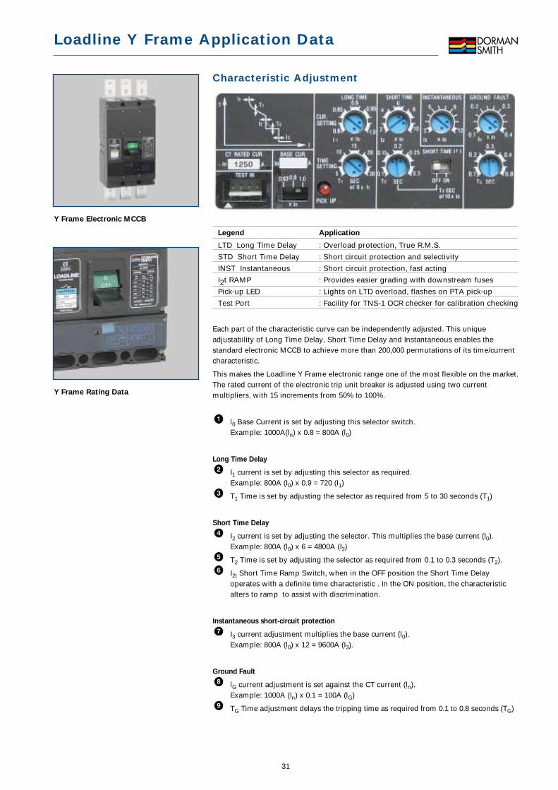
Characteristic Adjustment
Legend Application
LTD Long Time Delay : Overload protection, True R.M.S.
STD Short Time Delay : Short circuit protection and selectivity
INST Instantaneous : Short circuit protection, fast acting
I2t RAMP : Provides easier grading with downstream fuses
Pick-up LED : Lights on LTD overload, flashes on PTA pick-up
Test Port : Facility for TNS-1 OCR checker for calibration checking
Each part of the characteristic curve can be independently adjusted. This uniqueadjustability of Long Time Delay, Short Time Delay and Instantaneous enables thestandard electronic MCCB to achieve more than 200,000 permutations of its time/currentcharacteristic.
This makes the Loadline Y Frame electronic range one of the most flexible on the market.The rated current of the electronic trip unit breaker is adjusted using two currentmultipliers, with 15 increments from 50% to 100%.
l0 Base Current is set by adjusting this selector switch.Example: 1000A(ln) x 0.8 = 800A (l0)
Long Time Delay
I1 current is set by adjusting this selector as required.Example: 800A (I0) x 0.9 = 720 (I1)
T1 Time is set by adjusting the selector as required from 5 to 30 seconds (T1)
Short Time Delay
I2 current is set by adjusting the selector. This multiplies the base current (I0).Example: 800A (l0) x 6 = 4800A (I2)
T2 Time is set by adjusting the selector as required from 0.1 to 0.3 seconds (T2).
I2t Short Time Ramp Switch, when in the OFF position the Short Time Delayoperates with a definite time characteristic . In the ON position, the characteristicalters to ramp to assist with discrimination.
Instantaneous short-circuit protection
I3 current adjustment multiplies the base current (l0).Example: 800A (l0) x 12 = 9600A (I3).
Ground Fault
lG current adjustment is set against the CT current (ln).Example: 1000A (In) x 0.1 = 100A (lG)
TG Time adjustment delays the tripping time as required from 0.1 to 0.8 seconds (TG)9
8
Y Frame Electronic MCCB
Y Frame Rating Data
32
Loadline Y Frame Application Data
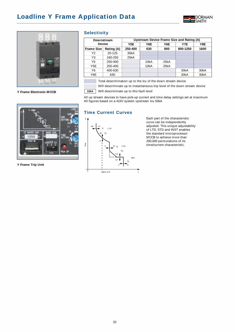
Selectivity
Total descrimination up to the Icu of the down stream device
Will descriminate up to instantaneous trip level of the down stream device
Will descriminate up to this fault level
All up stream devices to have pick-up current and time delay settings set at maximumAll figures based on a 415V system upstream Icu 50kA
Time Current CurvesEach part of the characteristic curve can be independently adjusted. This unique adjustability of LTD, STD and INST enables the standard microprocessor MCCB to achieve more than 200,000 permutations of its time/current characteristic.
0.8 1.0I1
T1
I2
T2
I3
30
5
2
3 12
10
0.3
0.1
600% of I1 I
T
L.T.D
S.T.D
INST.
Tim
e
10kAY Frame Electronic MCCB
Y Frame Trip Unit
Upstream Device Frame Size and Rating (A)Downstream
Device
250-400
35kA25kA
630
10kA10kA
Frame Size
Y2Y3Y5
Y5EY6
Y6E
Rating (A)
20-125160-250250-400250-400400-630
630
800
25kA25kA
800-1250
30kA30kA
1600
30kA30kA
Y5E Y6E Y6E Y7E Y8E
Quality Assurance and ASTA Certification
Quality AssuranceDorman Smith places the highest emphasis on the quality and performance of itsproducts. The standard of the company’s quality control systems and test resources isunsurpassed in the industry. Rigorous testing is undertaken to ensure that our productsmeet World Class standards with all manufacturing processes monitored and audited aspart of a Quality Management System approved to ISO9001.
Loadline MCCB Testing and CertificationLoadline MCCBs have been tested to provide secure, automatic protection fromoverload, short circuit and earth faults, as defined by IEC947-2. Furthermore, all LoadlineMCCBs enable switching and complete isolation of circuits in accordance with thestandard.
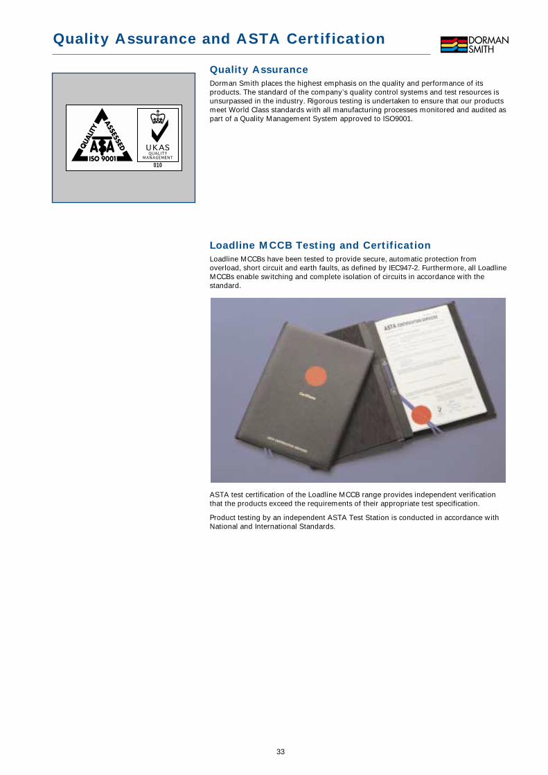
ASTA test certification of the Loadline MCCB range provides independent verificationthat the products exceed the requirements of their appropriate test specification.
Product testing by an independent ASTA Test Station is conducted in accordance withNational and International Standards.
010
33