Loadcenters and Circuit Breakers - Eatonpub/@electrical/documents/cont… · Volume 1—Residential...
101
Volume 1—Residential and Light Commercial CA08100002E—February 2018 www.eaton.com V1-T1-1 1 1 1 1 1 1 1 1 1 1 1 1 1 1 1 1 1 1 1 1 1 1 1 1 1 1 1 1 1 1 Loadcenters and Circuit Breakers Residential Loadcenters and Breaker Family 1.1 Type CH Loadcenters and Circuit Breakers Overview . . . . . . . . . . . . . . . . . . . . . . . . . . . . . . . . . . . . . . . . . . . . . . . V1-T1-2 Single-Phase . . . . . . . . . . . . . . . . . . . . . . . . . . . . . . . . . . . . . . . . . . V1-T1-6 Three-Phase . . . . . . . . . . . . . . . . . . . . . . . . . . . . . . . . . . . . . . . . . . . V1-T1-11 CH Specialty Products . . . . . . . . . . . . . . . . . . . . . . . . . . . . . . . . . . . . . V1-T1-13 Spa Panels . . . . . . . . . . . . . . . . . . . . . . . . . . . . . . . . . . . . . . . . . . . . V1-T1-13 Surge Panel . . . . . . . . . . . . . . . . . . . . . . . . . . . . . . . . . . . . . . . . . . . V1-T1-14 Plug-On Neutral Loadcenter. . . . . . . . . . . . . . . . . . . . . . . . . . . . . . . V1-T1-16 Type CH Renovation Loadcenter . . . . . . . . . . . . . . . . . . . . . . . . . . . V1-T1-17 Type CH Retrofit Interior Kits . . . . . . . . . . . . . . . . . . . . . . . . . . . . . V1-T1-18 Non-Metallic Loadcenter . . . . . . . . . . . . . . . . . . . . . . . . . . . . . . . . . V1-T1-20 CH Loadcenter Options and Accessories . . . . . . . . . . . . . . . . . . . . . . V1-T1-21 CH Circuit Breakers . . . . . . . . . . . . . . . . . . . . . . . . . . . . . . . . . . . . . . . V1-T1-31 1.2 Type BR Loadcenters and Circuit Breakers Overview . . . . . . . . . . . . . . . . . . . . . . . . . . . . . . . . . . . . . . . . . . . . . . . V1-T1-42 Single-Phase . . . . . . . . . . . . . . . . . . . . . . . . . . . . . . . . . . . . . . . . . . V1-T1-54 Three-Phase . . . . . . . . . . . . . . . . . . . . . . . . . . . . . . . . . . . . . . . . . . V1-T1-54 BR Specialty Products . . . . . . . . . . . . . . . . . . . . . . . . . . . . . . . . . . . . . V1-T1-57 BR Quick Connect Neutral Loadcenters . . . . . . . . . . . . . . . . . . . . . V1-T1-57 Spa Panels . . . . . . . . . . . . . . . . . . . . . . . . . . . . . . . . . . . . . . . . . . . V1-T1-58 Riser Panel . . . . . . . . . . . . . . . . . . . . . . . . . . . . . . . . . . . . . . . . . . . V1-T1-59 Type BR Renovation Loadcenter . . . . . . . . . . . . . . . . . . . . . . . . . . . V1-T1-60 Type BR Retrofit Interior Kits . . . . . . . . . . . . . . . . . . . . . . . . . . . . . V1-T1-61 BR Loadcenter Options and Accessories . . . . . . . . . . . . . . . . . . . . . . V1-T1-63 BR Circuit Breakers. . . . . . . . . . . . . . . . . . . . . . . . . . . . . . . . . . . . . . . . V1-T1-77 1.3 Loadcenter Interiors/OEM Loadcenters Product Description . . . . . . . . . . . . . . . . . . . . . . . . . . . . . . . . . . . . . . . V1-T1-89 Standards and Certifications . . . . . . . . . . . . . . . . . . . . . . . . . . . . . . . . . V1-T1-90 Product Selection . . . . . . . . . . . . . . . . . . . . . . . . . . . . . . . . . . . . . . . . . V1-T1-90 1.4 Enclosed Breakers Product Description . . . . . . . . . . . . . . . . . . . . . . . . . . . . . . . . . . . . . . . V1-T1-94 Standards and Certifications . . . . . . . . . . . . . . . . . . . . . . . . . . . . . . . . . V1-T1-94 Product Selection . . . . . . . . . . . . . . . . . . . . . . . . . . . . . . . . . . . . . . . . . V1-T1-95 Dimensions. . . . . . . . . . . . . . . . . . . . . . . . . . . . . . . . . . . . . . . . . . . . . . V1-T1-95 1.5 Classified Circuit Breakers Product Description . . . . . . . . . . . . . . . . . . . . . . . . . . . . . . . . . . . . . . . V1-T1-96 Product Selection . . . . . . . . . . . . . . . . . . . . . . . . . . . . . . . . . . . . . . . . . V1-T1-97 Accessories . . . . . . . . . . . . . . . . . . . . . . . . . . . . . . . . . . . . . . . . . . . . . V1-T1-99 Technical Data . . . . . . . . . . . . . . . . . . . . . . . . . . . . . . . . . . . . . . . . . . . . V1-T1-99 Wiring Diagrams . . . . . . . . . . . . . . . . . . . . . . . . . . . . . . . . . . . . . . . . . . V1-T1-100 Learn Online
Transcript of Loadcenters and Circuit Breakers - Eatonpub/@electrical/documents/cont… · Volume 1—Residential...
Volume 1—Residential and Light Commercial CA08100002E—February 2018 www.eaton.com V1-T1-1
1
1
1
1
1
1
1
1
1
1
1
1
1
1
1
1
1
1
1
1
1
1
1
1
1
1
1
1
1
1
Loadcenters and Circuit Breakers
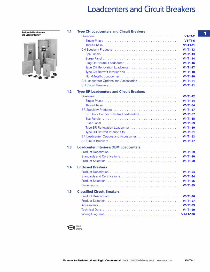
Residential Loadcenters and Breaker Family
1.1 Type CH Loadcenters and Circuit Breakers
Overview . . . . . . . . . . . . . . . . . . . . . . . . . . . . . . . . . . . . . . . . . . . . . . . V1-T1-2
Single-Phase . . . . . . . . . . . . . . . . . . . . . . . . . . . . . . . . . . . . . . . . . . V1-T1-6
Three-Phase. . . . . . . . . . . . . . . . . . . . . . . . . . . . . . . . . . . . . . . . . . . V1-T1-11
CH Specialty Products . . . . . . . . . . . . . . . . . . . . . . . . . . . . . . . . . . . . . V1-T1-13
Spa Panels . . . . . . . . . . . . . . . . . . . . . . . . . . . . . . . . . . . . . . . . . . . . V1-T1-13
Surge Panel . . . . . . . . . . . . . . . . . . . . . . . . . . . . . . . . . . . . . . . . . . . V1-T1-14
Plug-On Neutral Loadcenter. . . . . . . . . . . . . . . . . . . . . . . . . . . . . . . V1-T1-16
Type CH Renovation Loadcenter . . . . . . . . . . . . . . . . . . . . . . . . . . . V1-T1-17
Type CH Retrofit Interior Kits . . . . . . . . . . . . . . . . . . . . . . . . . . . . . V1-T1-18
Non-Metallic Loadcenter . . . . . . . . . . . . . . . . . . . . . . . . . . . . . . . . . V1-T1-20
CH Loadcenter Options and Accessories . . . . . . . . . . . . . . . . . . . . . . V1-T1-21
CH Circuit Breakers . . . . . . . . . . . . . . . . . . . . . . . . . . . . . . . . . . . . . . . V1-T1-31
1.2 Type BR Loadcenters and Circuit Breakers
Overview . . . . . . . . . . . . . . . . . . . . . . . . . . . . . . . . . . . . . . . . . . . . . . . V1-T1-42
Single-Phase . . . . . . . . . . . . . . . . . . . . . . . . . . . . . . . . . . . . . . . . . . V1-T1-54
Three-Phase . . . . . . . . . . . . . . . . . . . . . . . . . . . . . . . . . . . . . . . . . . V1-T1-54
BR Specialty Products . . . . . . . . . . . . . . . . . . . . . . . . . . . . . . . . . . . . . V1-T1-57
BR Quick Connect Neutral Loadcenters . . . . . . . . . . . . . . . . . . . . . V1-T1-57
Spa Panels . . . . . . . . . . . . . . . . . . . . . . . . . . . . . . . . . . . . . . . . . . . V1-T1-58
Riser Panel . . . . . . . . . . . . . . . . . . . . . . . . . . . . . . . . . . . . . . . . . . . V1-T1-59
Type BR Renovation Loadcenter . . . . . . . . . . . . . . . . . . . . . . . . . . . V1-T1-60
Type BR Retrofit Interior Kits . . . . . . . . . . . . . . . . . . . . . . . . . . . . . V1-T1-61
BR Loadcenter Options and Accessories . . . . . . . . . . . . . . . . . . . . . . V1-T1-63
BR Circuit Breakers. . . . . . . . . . . . . . . . . . . . . . . . . . . . . . . . . . . . . . . . V1-T1-77
1.3 Loadcenter Interiors/OEM Loadcenters
Product Description . . . . . . . . . . . . . . . . . . . . . . . . . . . . . . . . . . . . . . . V1-T1-89
Standards and Certifications. . . . . . . . . . . . . . . . . . . . . . . . . . . . . . . . . V1-T1-90
Product Selection . . . . . . . . . . . . . . . . . . . . . . . . . . . . . . . . . . . . . . . . . V1-T1-90
1.4 Enclosed Breakers
Product Description . . . . . . . . . . . . . . . . . . . . . . . . . . . . . . . . . . . . . . . V1-T1-94
Standards and Certifications. . . . . . . . . . . . . . . . . . . . . . . . . . . . . . . . . V1-T1-94
Product Selection . . . . . . . . . . . . . . . . . . . . . . . . . . . . . . . . . . . . . . . . . V1-T1-95
Dimensions. . . . . . . . . . . . . . . . . . . . . . . . . . . . . . . . . . . . . . . . . . . . . . V1-T1-95
1.5 Classified Circuit Breakers
Product Description . . . . . . . . . . . . . . . . . . . . . . . . . . . . . . . . . . . . . . . V1-T1-96
Product Selection . . . . . . . . . . . . . . . . . . . . . . . . . . . . . . . . . . . . . . . . . V1-T1-97
Accessories . . . . . . . . . . . . . . . . . . . . . . . . . . . . . . . . . . . . . . . . . . . . . V1-T1-99
Technical Data. . . . . . . . . . . . . . . . . . . . . . . . . . . . . . . . . . . . . . . . . . . . V1-T1-99
Wiring Diagrams . . . . . . . . . . . . . . . . . . . . . . . . . . . . . . . . . . . . . . . . . . V1-T1-100
LearnOnline
Volume 1—Residential and Light Commercial, CA08100002E
Tab 1—Loadcenters and Circuit BreakersRevision date Section Change page(s) Description
01/25/2018 1.1 V1-T1-2–V1-T1-30 Rearrange layout, content edits01/25/2018 1.1 V1-T1-38 Content edits01/25/2018 1.2 V1-T1-42–V1-T1-70 Rearrange layout, content edits01/25/2018 1.2 V1-T1-72–V1-T1-79 Content edits01/25/2018 1.2 V1-T1-85 Content edits01/25/2018 1.3 V1-T1-90 Content edits
02/19/2018 All All Change to revision date to match print version, February 2018
Revision notes
V1-T1-2 Volume 1—Residential and Light Commercial CA08100002E—February 2018 www.eaton.com
1
1
1
1
1
1
1
1
1
1
1
1
1
1
1
1
1
1
1
1
1
1
1
1
1
1
1
1
1
1
1.1 Loadcenters and Circuit Breakers
Type CH Loadcenters and Circuit Breakers
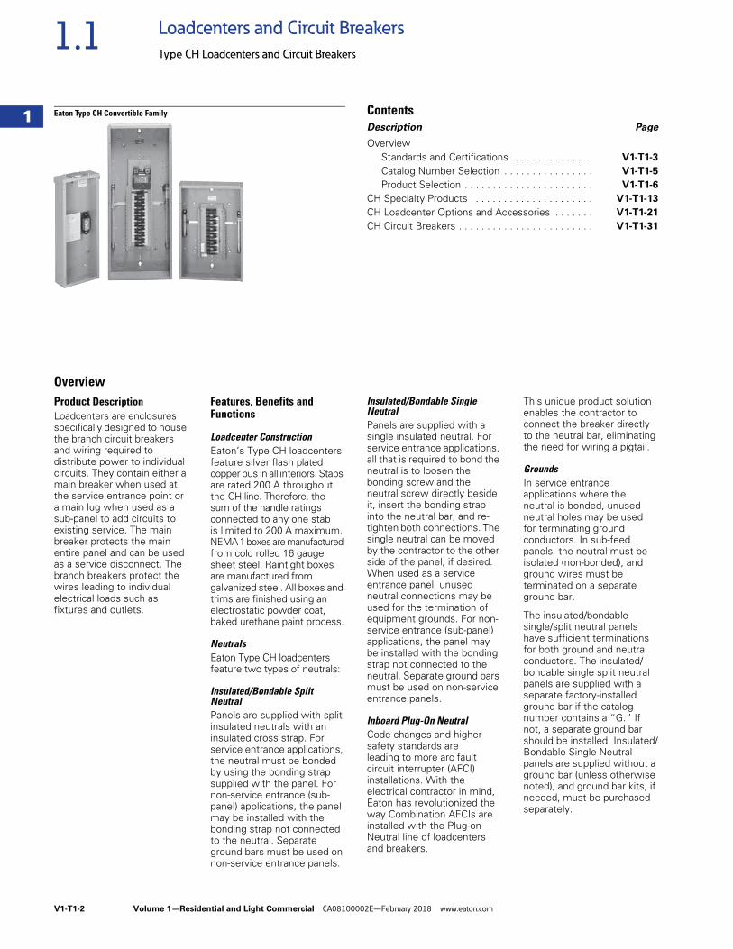
Eaton Type CH Convertible Family ContentsDescription Page
OverviewStandards and Certifications . . . . . . . . . . . . . . V1-T1-3
Catalog Number Selection . . . . . . . . . . . . . . . . V1-T1-5
Product Selection . . . . . . . . . . . . . . . . . . . . . . . V1-T1-6
CH Specialty Products . . . . . . . . . . . . . . . . . . . . . V1-T1-13
CH Loadcenter Options and Accessories . . . . . . . V1-T1-21
CH Circuit Breakers . . . . . . . . . . . . . . . . . . . . . . . . V1-T1-31
OverviewProduct Description Loadcenters are enclosures specifically designed to house the branch circuit breakers and wiring required to distribute power to individual circuits. They contain either a main breaker when used at the service entrance point or a main lug when used as a sub-panel to add circuits to existing service. The main breaker protects the main entire panel and can be used as a service disconnect. The branch breakers protect the wires leading to individual electrical loads such as fixtures and outlets.
Features, Benefits and Functions
Loadcenter ConstructionEaton’s Type CH loadcenters feature silver flash plated copper bus in all interiors. Stabs are rated 200 A throughout the CH line. Therefore, the sum of the handle ratings connected to any one stab is limited to 200 A maximum. NEMA 1 boxes are manufactured from cold rolled 16 gauge sheet steel. Raintight boxes are manufactured from galvanized steel. All boxes and trims are finished using an electrostatic powder coat, baked urethane paint process.
NeutralsEaton Type CH loadcenters feature two types of neutrals:
Insulated/Bondable Split NeutralPanels are supplied with split insulated neutrals with an insulated cross strap. For service entrance applications, the neutral must be bonded by using the bonding strap supplied with the panel. For non-service entrance (sub-panel) applications, the panel may be installed with the bonding strap not connected to the neutral. Separate ground bars must be used on non-service entrance panels.
Insulated/Bondable Single NeutralPanels are supplied with a single insulated neutral. For service entrance applications, all that is required to bond the neutral is to loosen the bonding screw and the neutral screw directly beside it, insert the bonding strap into the neutral bar, and re-tighten both connections. The single neutral can be moved by the contractor to the other side of the panel, if desired. When used as a service entrance panel, unused neutral connections may be used for the termination of equipment grounds. For non-service entrance (sub-panel) applications, the panel may be installed with the bonding strap not connected to the neutral. Separate ground bars must be used on non-service entrance panels.
Inboard Plug-On NeutralCode changes and higher safety standards are leading to more arc fault circuit interrupter (AFCI) installations. With the electrical contractor in mind, Eaton has revolutionized the way Combination AFCIs are installed with the Plug-on Neutral line of loadcenters and breakers.
This unique product solution enables the contractor to connect the breaker directly to the neutral bar, eliminating the need for wiring a pigtail.
GroundsIn service entrance applications where the neutral is bonded, unused neutral holes may be usedfor terminating ground conductors. In sub-feed panels, the neutral must be isolated (non-bonded), and ground wires must be terminated on a separate ground bar.
The insulated/bondable single/split neutral panels have sufficient terminations for both ground and neutral conductors. The insulated/bondable single split neutral panels are supplied with a separate factory-installed ground bar if the catalog number contains a “G.” If not, a separate ground bar should be installed. Insulated/Bondable Single Neutral panels are supplied without a ground bar (unless otherwise noted), and ground bar kits, if needed, must be purchased separately.
Volume 1—Residential and Light Commercial CA08100002E—February 2018 www.eaton.com V1-T1-3
1
1
1
1
1
1
1
1
1
1
1
1
1
1
1
1
1
1
1
1
1
1
1
1
1
1
1
1
1
1
1.1Loadcenters and Circuit Breakers
Type CH Loadcenters and Circuit Breakers
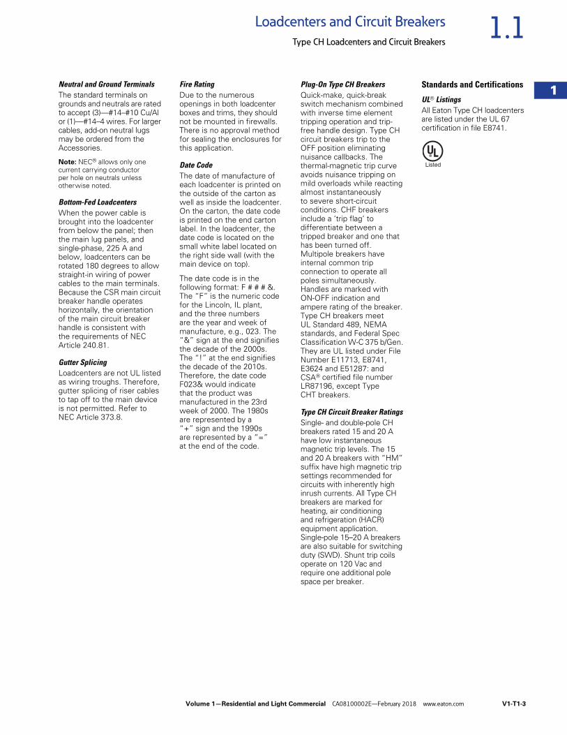
Neutral and Ground TerminalsThe standard terminals on grounds and neutrals are rated to accept (3)—#14–#10 Cu/Al or (1)—#14–4 wires. For larger cables, add-on neutral lugs may be ordered from the Accessories.
Note: NEC® allows only one current carrying conductor per hole on neutrals unless otherwise noted.
Bottom-Fed LoadcentersWhen the power cable is brought into the loadcenter from below the panel; then the main lug panels, and single-phase, 225 A and below, loadcenters can be rotated 180 degrees to allow straight-in wiring of power cables to the main terminals. Because the CSR main circuit breaker handle operates horizontally, the orientation of the main circuit breaker handle is consistent with the requirements of NEC Article 240.81.
Gutter SplicingLoadcenters are not UL listed as wiring troughs. Therefore, gutter splicing of riser cables to tap off to the main device is not permitted. Refer to NEC Article 373.8.
Fire RatingDue to the numerous openings in both loadcenter boxes and trims, they should not be mounted in firewalls. There is no approval method for sealing the enclosures for this application.
Date CodeThe date of manufacture of each loadcenter is printed on the outside of the carton as well as inside the loadcenter. On the carton, the date code is printed on the end carton label. In the loadcenter, the date code is located on the small white label located on the right side wall (with the main device on top).
The date code is in the following format: F # # # &. The “F” is the numeric code for the Lincoln, IL plant, and the three numbers are the year and week of manufacture, e.g., 023. The “&” sign at the end signifies the decade of the 2000s. The “!” at the end signifies the decade of the 2010s. Therefore, the date code F023& would indicate that the product was manufactured in the 23rd week of 2000. The 1980s are represented by a “+” sign and the 1990s are represented by a “=” at the end of the code.
Plug-On Type CH BreakersQuick-make, quick-break switch mechanism combined with inverse time element tripping operation and trip-free handle design. Type CH circuit breakers trip to the OFF position eliminating nuisance callbacks. The thermal-magnetic trip curve avoids nuisance tripping on mild overloads while reacting almost instantaneously to severe short-circuit conditions. CHF breakers include a ‘trip flag’ to differentiate between a tripped breaker and one that has been turned off. Multipole breakers have internal common trip connection to operate all poles simultaneously. Handles are marked with ON-OFF indication and ampere rating of the breaker. Type CH breakers meet UL Standard 489, NEMA standards, and Federal Spec Classification W-C 375 b/Gen. They are UL listed under File Number E11713, E8741, E3624 and E51287: and CSA® certified file number LR87196, except Type CHT breakers.
Type CH Circuit Breaker RatingsSingle- and double-pole CH breakers rated 15 and 20 A have low instantaneous magnetic trip levels. The 15 and 20 A breakers with “HM” suffix have high magnetic trip settings recommended for circuits with inherently high inrush currents. All Type CH breakers are marked for heating, air conditioning and refrigeration (HACR) equipment application. Single-pole 15–20 A breakers are also suitable for switching duty (SWD). Shunt trip coils operate on 120 Vac and require one additional pole space per breaker.
Standards and Certifications
UL® ListingsAll Eaton Type CH loadcenters are listed under the UL 67 certification in file E8741.
V1-T1-4 Volume 1—Residential and Light Commercial CA08100002E—February 2018 www.eaton.com
1
1
1
1
1
1
1
1
1
1
1
1
1
1
1
1
1
1
1
1
1
1
1
1
1
1
1
1
1
1
1.1 Loadcenters and Circuit Breakers
Type CH Loadcenters and Circuit Breakers
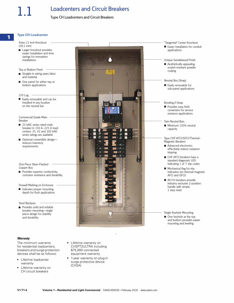
Type CH Loadcenter
WarrantyThe minimum warranty for residential loadcenters, breakers and surge protection devices shall be as follows:
● Lifetime loadcenter warranty
● Lifetime warranty on CH circuit breakers
● Lifetime warranty on CHSPT2ULTRA including $75,000 connected equipment warranty
● 1-year warranty on plug-in surge protective device (CHSA)
Single Keyhole Mounting
One keyhole at the top and bottom provides easier mounting and leveling
Neutral Bus (Strap)
Easily removable for sub-panel applications
Bonding Z-Strap
Provides easy field conversion for service entrance applications
Twin Neutral Bars
Minimum 150% neutral capacity
Extra 1.5 inch Knockout (38.1 mm)
Larger knockout provides easier installation and time savings for renovation installations
“Tangential” Center Knockout
Easier installation for conduit applications
Commercial Grade Main Breaker
25 kAIC series rated main breaker in 150 A–225 A load-centers. 35, 42 and 100 kAIC series ratings are available
Optional convertible design— reduces inventory requirements
2/0 Lug
Easily removable and can be installed in any location on the neutral bar
Drywall Marking on Enclosure
Indicates proper mounting depth for flush applications
One Piece Silver-Flashed Copper Bus
Provides superior conductivity, corrosion resistance and durability
Steel Backpan
Provides solid and reliable breaker mounting—single piece design for stability
and durability
Top or Bottom Feed
Straight-in wiring saves labor and material
One panel for either top or bottom applications
Type CHF AFCI/GFCI/Thermal - Magnetic Breakers
Advanced electronics effectively reduce nuisance tripping
CHF AFCI breakers have a standard diagnostic LED indicating 1 of 7 trip codes
Mechanical flag for trip indication (on thermal-magnetic AFCI and GFCI)
All CH breakers provide industry exclusive 2-position handle with simple 1 step reset
Unique Sandalwood Finish
Aesthetically appealing, scratch-resistant powder coating
■
■
■
■
■
■
■
■
■
■
■
■
■
■
■
■
■
■
■
Volume 1—Residential and Light Commercial CA08100002E—February 2018 www.eaton.com V1-T1-5
1
1
1
1
1
1
1
1
1
1
1
1
1
1
1
1
1
1
1
1
1
1
1
1
1
1
1
1
1
1
1.1Loadcenters and Circuit Breakers
Type CH Loadcenters and Circuit Breakers
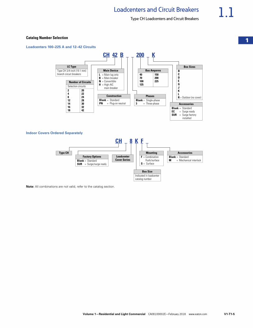
Catalog Number Selection
Loadcenters 100–225 A and 12–42 Circuits
Indoor Covers Ordered Separately
Note: All combinations are not valid, refer to the catalog section.
LC TypeType CH 3/4-inch (19.1 mm)branch circuit breakers
Number of CircuitsSelection circuits24812141618
20222428303242
Main DeviceL = Main lug onlyB = Main breakerN = ConvertibleH = High AIC
main breaker
CH 42 B 200 K
ConstructionBlank = StandardPN = Plug-on neutral
PhasesBlank = Single-phase3 = Three-phase Accessories
Blank = StandardEC = Surge readySUR = Surge factory
installed
Bus Amperes4070100125
150200225
Box SizesBCDEGJKLR = Outdoor (no cover)
CH 8 K F
Type CHLoadcenter
Cover SeriesFactory Options
Blank = Standard SUR = Surge/surge ready
AccessoriesBlank = StandardM = Mechanical interlock
MountingF = Combination
flush/surfaceS = Surface
Box SizeIndicated in loadcentercatalog number
V1-T1-6 Volume 1—Residential and Light Commercial CA08100002E—February 2018 www.eaton.com
1
1
1
1
1
1
1
1
1
1
1
1
1
1
1
1
1
1
1
1
1
1
1
1
1
1
1
1
1
1
1.1 Loadcenters and Circuit Breakers
Type CH Loadcenters and Circuit Breakers
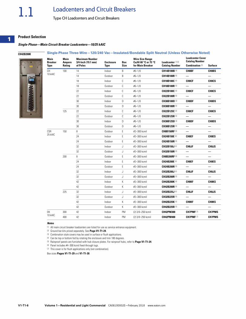
Product Selection
Single-Phase—Main Circuit Breaker Loadcenters—10/25 kAIC
Single-Phase Three-Wire—120/240 Vac—Insulated/Bondable Split Neutral (Unless Otherwise Noted)
Notes1 All main circuit breaker loadcenters are listed for use as service entrance equipment.2 Ground bar kits priced separately. See Page V1-T1-24.3 Combination style covers may be used in surface or flush applications.4 Can be top or bottom fed by rotating the enclosure and trim 180 degrees.5 Rainproof panels are furnished with hub closure plates. For rainproof hubs, refer to Page V1-T1-24.6 Panel includes #4–300 kcmil feed-through lugs.7 This cover is for flush applications only (not combination).
Box sizes Pages V1-T1-29 and V1-T1-30.
MainBreakerType
MainAmpereRating
Maximum Number3/4-Inch (19.1 mm)of Poles
EnclosureType
BoxSize
Wire Size RangeCu/Al 60 °C or 75 °Cfor Main Breaker
Loadcenter 12
Catalog Number
Loadcenter CoverCatalog NumberCombination 3 Surface
CH10 kAIC
100 14 Indoor B #6–1/0 CH14B100B 4 CH8BF CH8BS
14 Outdoor B #6–1/0 CH14B100R 5 — —
18 Indoor C #6–1/0 CH18B100C 4 CH8CF CH8CS
18 Outdoor C #6–1/0 CH18B100R 5 — —
22 Indoor C #6–1/0 CH22B100C 4 CH8CF CH8CS
22 Outdoor C #6–1/0 CH22B100R 5 — —
30 Indoor D #6–1/0 CH30B100D 4 CH8DF CH8DS
30 Outdoor D #6–1/0 CH30B100R 5 — —
125 22 Indoor C #6–1/0 CH22B125C 4 CH8CF CH8CS
22 Outdoor C #6–1/0 CH22B125R 5 — —
30 Indoor D #6–1/0 CH30B125D 4 CH8DF CH8DS
30 Outdoor D #6–1/0 CH30B125R 5 — —
CSR25 kAIC
150 8 Outdoor E #2–300 kcmil CH8B150RF 6 — —
24 Indoor E #2–300 kcmil CH24B150E 4 CH8EF CH8ES
24 Outdoor E #2–300 kcmil CH24B150R 5 — —
32 Indoor J #2–300 kcmil CH32B150J 4 CH8JF CH8JS
32 Outdoor J #2–300 kcmil CH32B150R 5 — —
200 8 Outdoor E #2–300 kcmil CH8B200RF 6 — —
24 Indoor E #2–300 kcmil CH24B200E 4 CH8EF CH8ES
24 Outdoor E #2–300 kcmil CH24B200R 5 — —
32 Indoor J #2–300 kcmil CH32B200J 4 CH8JF CH8JS
32 Outdoor J #2–300 kcmil CH32B200R 5 — —
42 Indoor K #2–300 kcmil CH42B200K 4 CH8KF CH8KS
42 Outdoor K #2–300 kcmil CH42B200R 5 — —
225 32 Indoor J #2–300 kcmil CH32B225J 4 CH8JF CH8JS
32 Outdoor J #2–300 kcmil CH32B225R 5 — —
42 Indoor K #2–300 kcmil CH42B225K 4 CH8KF CH8KS
42 Outdoor K #2–300 kcmil CH42B225R 5 — —
DK10 kAIC
300 42 Indoor PM (2) 3/0–250 kcmil CH42PM300 CH7PMF 7 CH7PMS
400 42 Indoor PM (2) 3/0–250 kcmil CH42PM400 CH7PMF 7 CH7PMS
CH42B200K
Volume 1—Residential and Light Commercial CA08100002E—February 2018 www.eaton.com V1-T1-7
1
1
1
1
1
1
1
1
1
1
1
1
1
1
1
1
1
1
1
1
1
1
1
1
1
1
1
1
1
1
1.1Loadcenters and Circuit Breakers
Type CH Loadcenters and Circuit Breakers
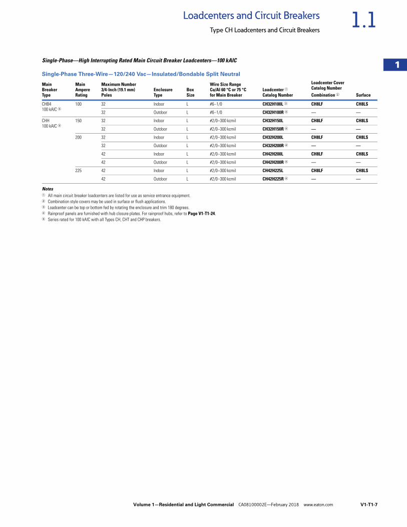
Single-Phase—High Interrupting Rated Main Circuit Breaker Loadcenters—100 kAIC
Single-Phase Three-Wire—120/240 Vac—Insulated/Bondable Split Neutral
Notes1 All main circuit breaker loadcenters are listed for use as service entrance equipment.2 Combination style covers may be used in surface or flush applications.3 Loadcenter can be top or bottom fed by rotating the enclosure and trim 180 degrees.4 Rainproof panels are furnished with hub closure plates. For rainproof hubs, refer to Page V1-T1-24. 5 Series rated for 100 kAIC with all Types CH, CHT and CHP breakers.
MainBreakerType
MainAmpereRating
Maximum Number3/4-Inch (19.1 mm)Poles
EnclosureType
BoxSize
Wire Size RangeCu/Al 60 °C or 75 °Cfor Main Breaker
Loadcenter 1Catalog Number
Loadcenter CoverCatalog NumberCombination 2 Surface
CHB4100 kAIC 5
100 32 Indoor L #6–1/0 CH32H100L 3 CH8LF CH8LS
32 Outdoor L #6–1/0 CH32H100R 4 — —
CHH100 kAIC 5
150 32 Indoor L #2/0–300 kcmil CH32H150L CH8LF CH8LS
32 Outdoor L #2/0–300 kcmil CH32H150R 4 — —
200 32 Indoor L #2/0–300 kcmil CH32H200L CH8LF CH8LS
32 Outdoor L #2/0–300 kcmil CH32H200R 4 — —
42 Indoor L #2/0–300 kcmil CH42H200L CH8LF CH8LS
42 Outdoor L #2/0–300 kcmil CH42H200R 4 — —
225 42 Indoor L #2/0–300 kcmil CH42H225L CH8LF CH8LS
42 Outdoor L #2/0–300 kcmil CH42H225R 4 — —
V1-T1-8 Volume 1—Residential and Light Commercial CA08100002E—February 2018 www.eaton.com
1
1
1
1
1
1
1
1
1
1
1
1
1
1
1
1
1
1
1
1
1
1
1
1
1
1
1
1
1
1
1.1 Loadcenters and Circuit Breakers
Type CH Loadcenters and Circuit Breakers
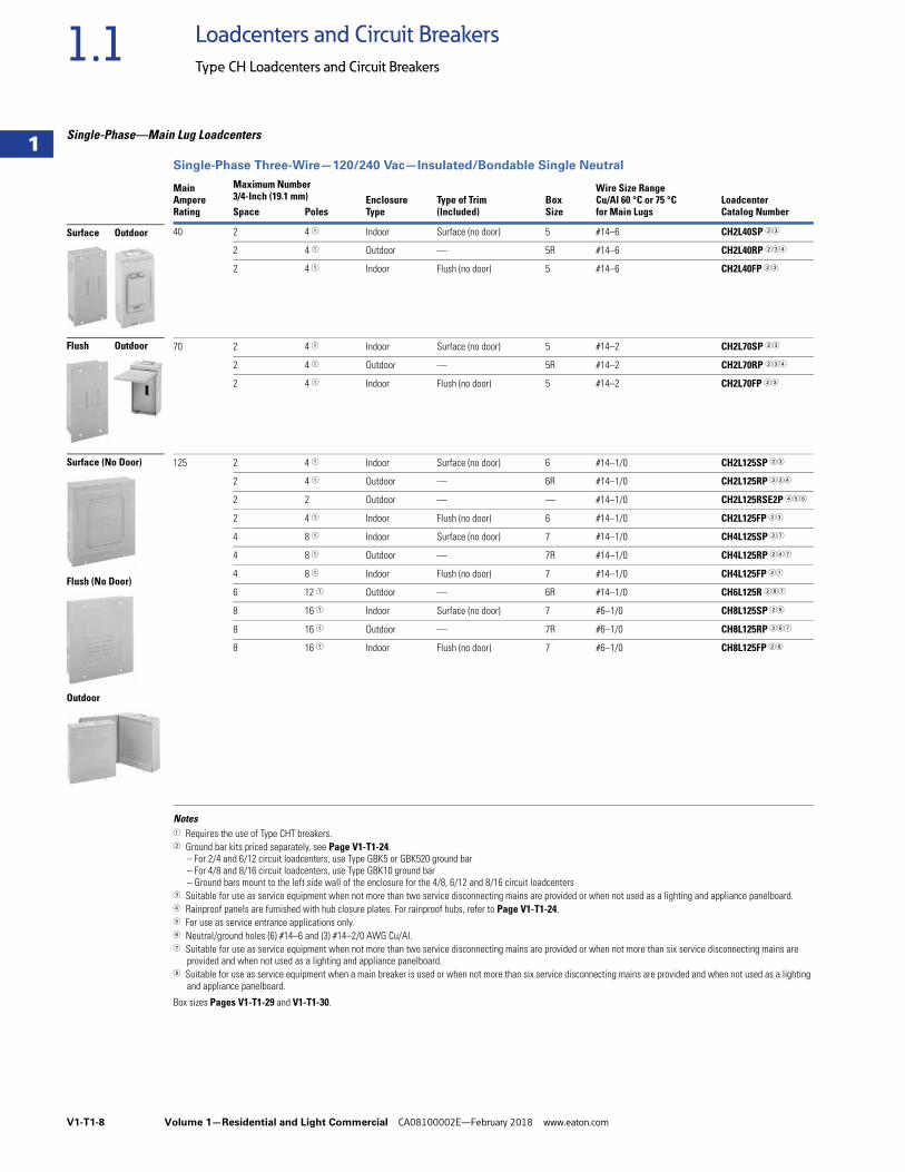
Single-Phase—Main Lug Loadcenters
Single-Phase Three-Wire—120/240 Vac—Insulated/Bondable Single Neutral
Notes1 Requires the use of Type CHT breakers.2 Ground bar kits priced separately, see Page V1-T1-24.
– For 2/4 and 6/12 circuit loadcenters, use Type GBK5 or GBK520 ground bar– For 4/8 and 8/16 circuit loadcenters, use Type GBK10 ground bar– Ground bars mount to the left side wall of the enclosure for the 4/8, 6/12 and 8/16 circuit loadcenters
3 Suitable for use as service equipment when not more than two service disconnecting mains are provided or when not used as a lighting and appliance panelboard.4 Rainproof panels are furnished with hub closure plates. For rainproof hubs, refer to Page V1-T1-24.5 For use as service entrance applications only.6 Neutral/ground holes (6) #14–6 and (3) #14–2/0 AWG Cu/AI.7 Suitable for use as service equipment when not more than two service disconnecting mains are provided or when not more than six service disconnecting mains are
provided and when not used as a lighting and appliance panelboard.8 Suitable for use as service equipment when a main breaker is used or when not more than six service disconnecting mains are provided and when not used as a lighting
and appliance panelboard.
Box sizes Pages V1-T1-29 and V1-T1-30.
MainAmpereRating
Maximum Number3/4-Inch (19.1 mm) Enclosure
TypeType of Trim(Included)
BoxSize
Wire Size RangeCu/Al 60 °C or 75 °Cfor Main Lugs
LoadcenterCatalog NumberSpace Poles
40 2 4 1 Indoor Surface (no door) 5 #14–6 CH2L40SP 23
2 4 1 Outdoor — 5R #14–6 CH2L40RP 234
2 4 1 Indoor Flush (no door) 5 #14–6 CH2L40FP 23
70 2 4 1 Indoor Surface (no door) 5 #14–2 CH2L70SP 23
2 4 1 Outdoor — 5R #14–2 CH2L70RP 234
2 4 1 Indoor Flush (no door) 5 #14–2 CH2L70FP 23
125 2 4 1 Indoor Surface (no door) 6 #14–1/0 CH2L125SP 23
2 4 1 Outdoor — 6R #14–1/0 CH2L125RP 234
2 2 Outdoor — — #14–1/0 CH2L125RSE2P 456
2 4 1 Indoor Flush (no door) 6 #14–1/0 CH2L125FP 23
4 8 1 Indoor Surface (no door) 7 #14–1/0 CH4L125SP 27
4 8 1 Outdoor — 7R #14–1/0 CH4L125RP 247
4 8 1 Indoor Flush (no door) 7 #14–1/0 CH4L125FP 27
6 12 1 Outdoor — 6R #14–1/0 CH6L125R 267
8 16 1 Indoor Surface (no door) 7 #6–1/0 CH8L125SP 28
8 16 1 Outdoor — 7R #6–1/0 CH8L125RP 267
8 16 1 Indoor Flush (no door) 7 #6–1/0 CH8L125FP 28
Surface Outdoor
Flush Outdoor
Surface (No Door)
Flush (No Door)
Outdoor
Volume 1—Residential and Light Commercial CA08100002E—February 2018 www.eaton.com V1-T1-9
1
1
1
1
1
1
1
1
1
1
1
1
1
1
1
1
1
1
1
1
1
1
1
1
1
1
1
1
1
1
1.1Loadcenters and Circuit Breakers
Type CH Loadcenters and Circuit Breakers
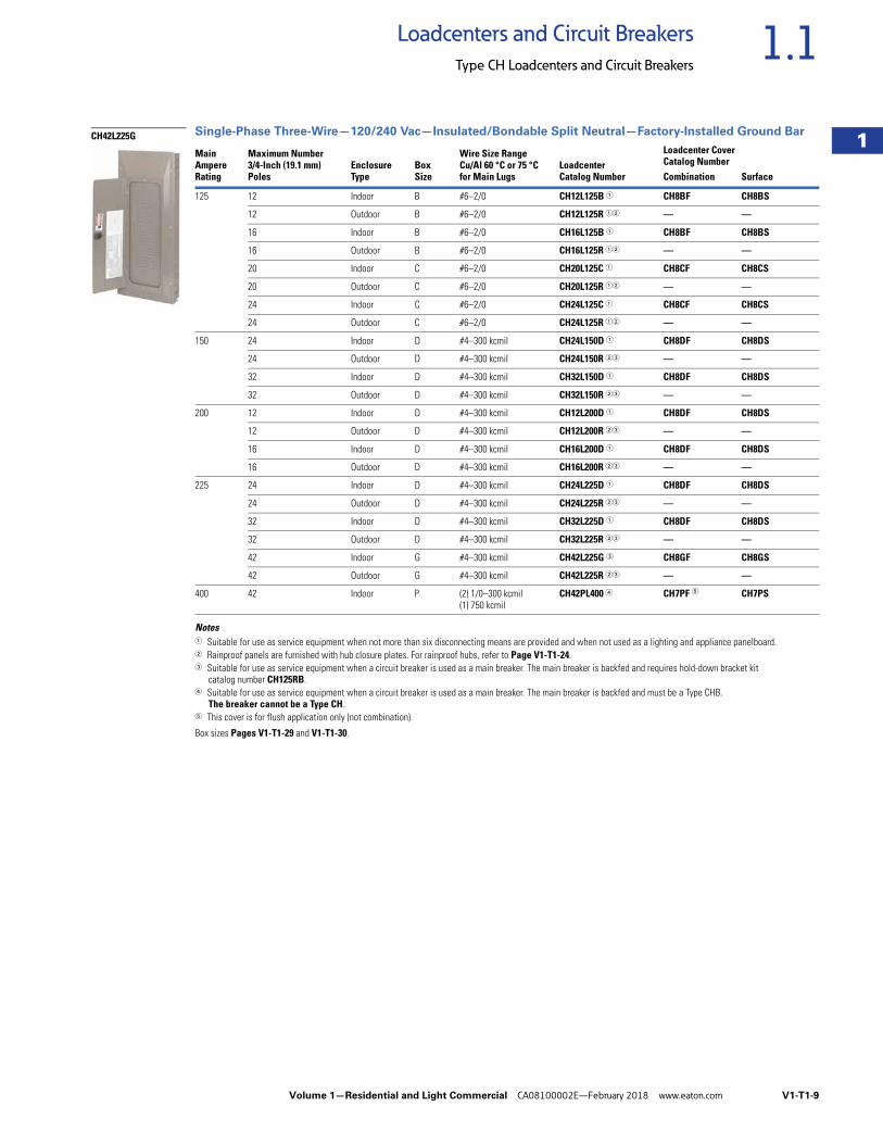
Single-Phase Three-Wire—120/240 Vac—Insulated/Bondable Split Neutral—Factory-Installed Ground Bar
Notes1 Suitable for use as service equipment when not more than six disconnecting means are provided and when not used as a lighting and appliance panelboard.2 Rainproof panels are furnished with hub closure plates. For rainproof hubs, refer to Page V1-T1-24.3 Suitable for use as service equipment when a circuit breaker is used as a main breaker. The main breaker is backfed and requires hold-down bracket kit
catalog number CH125RB.4 Suitable for use as service equipment when a circuit breaker is used as a main breaker. The main breaker is backfed and must be a Type CHB.
The breaker cannot be a Type CH.5 This cover is for flush application only (not combination).
Box sizes Pages V1-T1-29 and V1-T1-30.
MainAmpereRating
Maximum Number3/4-Inch (19.1 mm)Poles
EnclosureType
BoxSize
Wire Size RangeCu/Al 60 °C or 75 °Cfor Main Lugs
LoadcenterCatalog Number
Loadcenter CoverCatalog NumberCombination Surface
125 12 Indoor B #6–2/0 CH12L125B 1 CH8BF CH8BS
12 Outdoor B #6–2/0 CH12L125R 12 — —
16 Indoor B #6–2/0 CH16L125B 1 CH8BF CH8BS
16 Outdoor B #6–2/0 CH16L125R 12 — —
20 Indoor C #6–2/0 CH20L125C 1 CH8CF CH8CS
20 Outdoor C #6–2/0 CH20L125R 12 — —
24 Indoor C #6–2/0 CH24L125C 1 CH8CF CH8CS
24 Outdoor C #6–2/0 CH24L125R 12 — —
150 24 Indoor D #4–300 kcmil CH24L150D 1 CH8DF CH8DS
24 Outdoor D #4–300 kcmil CH24L150R 23 — —
32 Indoor D #4–300 kcmil CH32L150D 1 CH8DF CH8DS
32 Outdoor D #4–300 kcmil CH32L150R 23 — —
200 12 Indoor D #4–300 kcmil CH12L200D 1 CH8DF CH8DS
12 Outdoor D #4–300 kcmil CH12L200R 23 — —
16 Indoor D #4–300 kcmil CH16L200D 1 CH8DF CH8DS
16 Outdoor D #4–300 kcmil CH16L200R 23 — —
225 24 Indoor D #4–300 kcmil CH24L225D 1 CH8DF CH8DS
24 Outdoor D #4–300 kcmil CH24L225R 23 — —
32 Indoor D #4–300 kcmil CH32L225D 1 CH8DF CH8DS
32 Outdoor D #4–300 kcmil CH32L225R 23 — —
42 Indoor G #4–300 kcmil CH42L225G 3 CH8GF CH8GS
42 Outdoor G #4–300 kcmil CH42L225R 23 — —
400 42 Indoor P (2) 1/0–300 kcmil(1) 750 kcmil
CH42PL400 4 CH7PF 5 CH7PS
CH42L225G
V1-T1-10 Volume 1—Residential and Light Commercial CA08100002E—February 2018 www.eaton.com
1
1
1
1
1
1
1
1
1
1
1
1
1
1
1
1
1
1
1
1
1
1
1
1
1
1
1
1
1
1
1.1 Loadcenters and Circuit Breakers
Type CH Loadcenters and Circuit Breakers
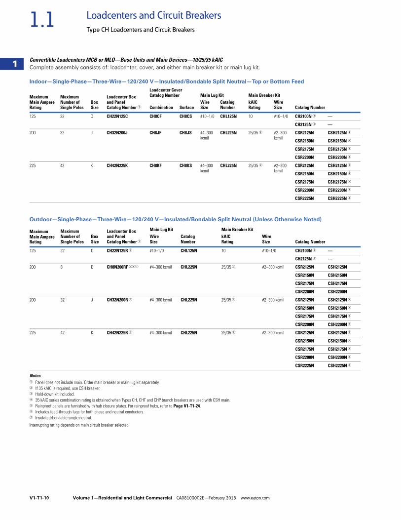
Convertible Loadcenters MCB or MLO—Base Units and Main Devices—10/25/35 kAIC Complete assembly consists of: loadcenter, cover, and either main breaker kit or main lug kit.
Indoor—Single-Phase—Three-Wire—120/240 V—Insulated/Bondable Split Neutral—Top or Bottom Feed
Outdoor—Single-Phase—Three-Wire—120/240 V—Insulated/Bondable Split Neutral (Unless Otherwise Noted)
Notes1 Panel does not include main. Order main breaker or main lug kit separately.2 If 35 kAIC is required, use CSH breaker.3 Hold-down kit included.4 35 kAIC series combination rating is obtained when Types CH, CHT and CHP branch breakers are used with CSH main.5 Rainproof panels are furnished with hub closure plates. For rainproof hubs, refer to Page V1-T1-24.6 Includes feed-through lugs for both phase and neutral conductors.7 Insulated/bondable single neutral.
Interrupting rating depends on main circuit breaker selected.
MaximumMain AmpereRating
MaximumNumber of Single Poles
BoxSize
Loadcenter Box and PanelCatalog Number 1
Loadcenter CoverCatalog Number Main Lug Kit Main Breaker Kit
Catalog NumberCombination SurfaceWire Size
Catalog Number
kAIC Rating
Wire Size
125 22 C CH22N125C CH8CF CH8CS #10–1/0 CHL125N 10 #10–1/0 CH2100N 3 —
CH2125N 3 —
200 32 J CH32N200J CH8JF CH8JS #4–300kcmil
CHL225N 25/35 2 #2–300kcmil
CSR2125N CSH2125N 4
CSR2150N CSH2150N 4
CSR2175N CSH2175N 4
CSR2200N CSH2200N 4
225 42 K CH42N225K CH8KF CH8KS #4–300kcmil
CHL225N 25/35 2 #2–300kcmil
CSR2125N CSH2125N 4
CSR2150N CSH2150N 4
CSR2175N CSH2175N 4
CSR2200N CSH2200N 4
CSR2225N CSH2225N 4
MaximumMain AmpereRating
MaximumNumber of Single Poles
BoxSize
Loadcenter Boxand PanelCatalog Number 1
Main Lug KitCatalog Number
Main Breaker Kit
Catalog NumberWire Size
kAIC Rating
Wire Size
125 22 C CH22N125R 5 #10–1/0 CHL125N 10 #10–1/0 CH2100N 3 —
CH2125N 3 —
200 8 E CH8N200RF 567 #4–300 kcmil CHL225N 25/35 2 #2–300 kcmil CSR2125N CSH2125N
CSR2150N CSH2150N
CSR2175N CSH2175N
CSR2200N CSH2200N
200 32 J CH32N200R 5 #4–300 kcmil CHL225N 25/35 2 #2–300 kcmil CSR2125N CSH2125N 4
CSR2150N CSH2150N 4
CSR2175N CSH2175N 4
CSR2200N CSH2200N 4
225 42 K CH42N225R 5 #4–300 kcmil CHL225N 25/35 2 #2–300 kcmil CSR2125N CSH2125N 4
CSR2150N CSH2150N 4
CSR2175N CSH2175N 4
CSR2200N CSH2200N 4
CSR2225N CSH2225N 4
Volume 1—Residential and Light Commercial CA08100002E—February 2018 www.eaton.com V1-T1-11
1
1
1
1
1
1
1
1
1
1
1
1
1
1
1
1
1
1
1
1
1
1
1
1
1
1
1
1
1
1
1.1Loadcenters and Circuit Breakers
Type CH Loadcenters and Circuit Breakers
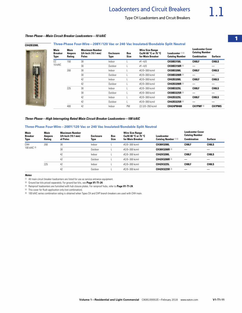
Three-Phase—Main Circuit Breaker Loadcenters—10 kAIC
Three-Phase Four-Wire—208Y/120 Vac or 240 Vac Insulated/Bondable Split Neutral
Three-Phase—High Interrupting Rated Main Circuit Breaker Loadcenters—100 kAIC
Three-Phase Four-Wire—208Y/120 Vac or 240 Vac Insulated/Bondable Split Neutral
Notes1 All main circuit breaker loadcenters are listed for use as service entrance equipment.2 Ground bar kits priced separately. For ground bar kits, see Page V1-T1-24.3 Rainproof loadcenters are furnished with hub closure plates. For rainproof hubs, refer to Page V1-T1-24.4 This cover for flush application only (not combination).5 100 kAIC series combination rating is obtained when Types CH and CHP branch breakers are used with CHH main.
MainBreakerType
MainAmpereRating
Maximum Number3/4-Inch (19.1 mm)Poles
EnclosureType
BoxSize
Wire Size RangeCu/Al 60 °C or 75 °Cfor Main Breaker
Loadcenter 12
Catalog Number
Loadcenter CoverCatalog NumberCombination Surface
CC10 kAIC
150 30 Indoor L #1–4/0 CH30B3150L CH8LF CH8LS
30 Outdoor L #1–4/0 CH30B3150R 3 — —
200 30 Indoor L #2/0–300 kcmil CH30B3200L CH8LF CH8LS
30 Outdoor L #2/0–300 kcmil CH30B3200R 3 — —
42 Indoor L #2/0–300 kcmil CH42B3200L CH8LF CH8LS
42 Outdoor L #2/0–300 kcmil CH42B3200R 3 — —
225 30 Indoor L #2/0–300 kcmil CH30B3225L CH8LF CH8LS
30 Outdoor L #2/0–300 kcmil CH30B3225R 3 — —
42 Indoor L #2/0–300 kcmil CH42B3225L CH8LF CH8LS
42 Outdoor L #2/0–300 kcmil CH42B3225R 3 — —
400 42 Indoor PM (2) 3/0–350 kcmil CH424PM400 CH7PMF 4 CH7PMS
Main Breaker Type
Main AmpereRating
Maximum Number 3/4-Inch (19.1 mm)of Poles
EnclosureType
Box Size
Wire Size Range Cu/Al 60 °C or 75 °Cfor Main Breaker
Loadcenter Catalog Number 12
Loadcenter Cover Catalog NumberCombination Surface
CHH100 kAIC 5
200 30 Indoor L #2/0–300 kcmil CH30H3200L CH8LF CH8LS
30 Outdoor L #2/0–300 kcmil CH30H3200R 3 — —
42 Indoor L #2/0–300 kcmil CH42H3200L CH8LF CH8LS
42 Outdoor L #2/0–300 kcmil CH42H3200R 3 — —
225 42 Indoor L #2/0–300 kcmil CH42H3225L CH8LF CH8LS
42 Outdoor L #2/0–300 kcmil CH42H3225R 3 — —
CH42B3200L
V1-T1-12 Volume 1—Residential and Light Commercial CA08100002E—February 2018 www.eaton.com
1
1
1
1
1
1
1
1
1
1
1
1
1
1
1
1
1
1
1
1
1
1
1
1
1
1
1
1
1
1
1.1 Loadcenters and Circuit Breakers
Type CH Loadcenters and Circuit Breakers
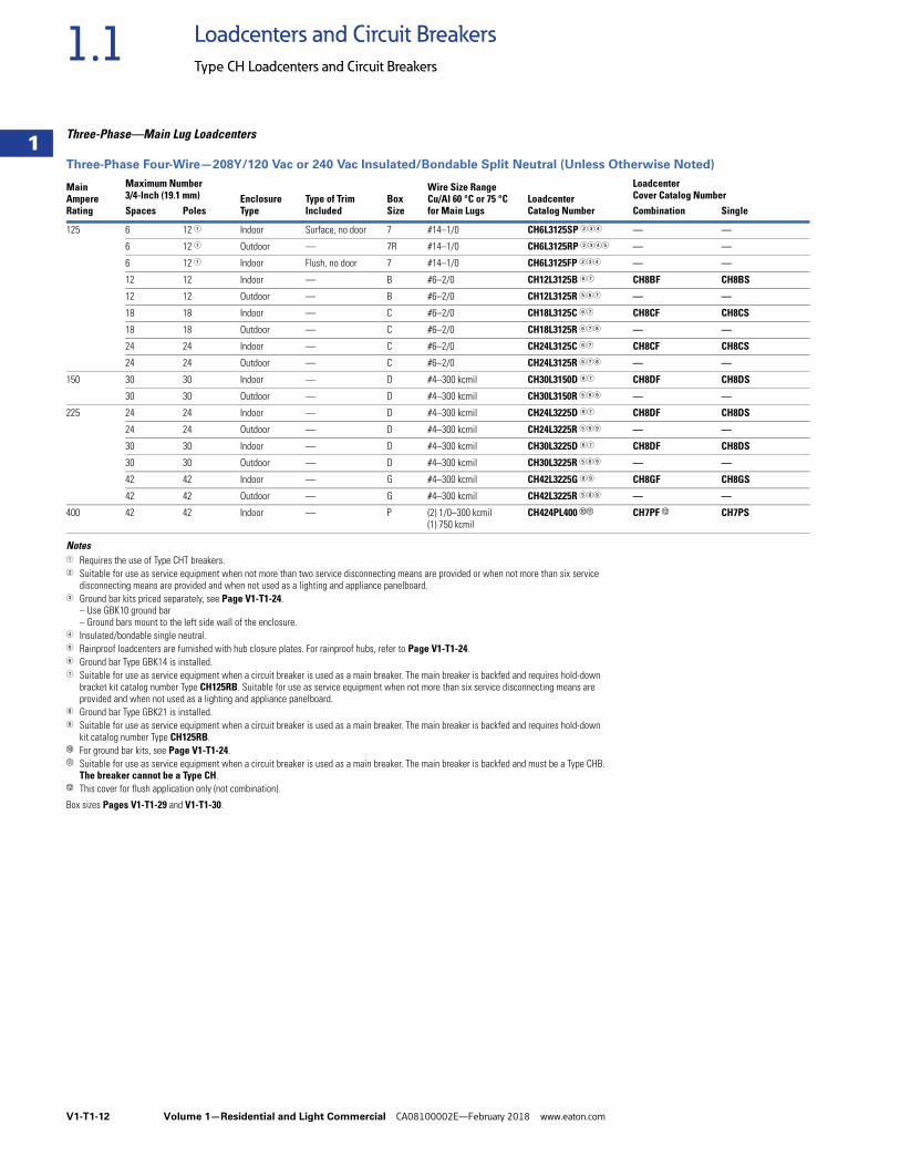
Three-Phase—Main Lug Loadcenters
Three-Phase Four-Wire—208Y/120 Vac or 240 Vac Insulated/Bondable Split Neutral (Unless Otherwise Noted)
Notes1 Requires the use of Type CHT breakers.2 Suitable for use as service equipment when not more than two service disconnecting means are provided or when not more than six service
disconnecting means are provided and when not used as a lighting and appliance panelboard.3 Ground bar kits priced separately, see Page V1-T1-24.
– Use GBK10 ground bar– Ground bars mount to the left side wall of the enclosure.
4 Insulated/bondable single neutral.5 Rainproof loadcenters are furnished with hub closure plates. For rainproof hubs, refer to Page V1-T1-24.6 Ground bar Type GBK14 is installed.7 Suitable for use as service equipment when a circuit breaker is used as a main breaker. The main breaker is backfed and requires hold-down
bracket kit catalog number Type CH125RB. Suitable for use as service equipment when not more than six service disconnecting means are provided and when not used as a lighting and appliance panelboard.
8 Ground bar Type GBK21 is installed.9 Suitable for use as service equipment when a circuit breaker is used as a main breaker. The main breaker is backfed and requires hold-down
kit catalog number Type CH125RB.j For ground bar kits, see Page V1-T1-24. k Suitable for use as service equipment when a circuit breaker is used as a main breaker. The main breaker is backfed and must be a Type CHB.
The breaker cannot be a Type CH.l This cover for flush application only (not combination).
Box sizes Pages V1-T1-29 and V1-T1-30.
MainAmpereRating
Maximum Number3/4-Inch (19.1 mm) Enclosure
TypeType of TrimIncluded
BoxSize
Wire Size RangeCu/Al 60 °C or 75 °Cfor Main Lugs
LoadcenterCatalog Number
Loadcenter Cover Catalog Number
Spaces Poles Combination Single
125 6 12 1 Indoor Surface, no door 7 #14–1/0 CH6L3125SP 234 — —
6 12 1 Outdoor — 7R #14–1/0 CH6L3125RP 2345 — —
6 12 1 Indoor Flush, no door 7 #14–1/0 CH6L3125FP 234 — —
12 12 Indoor — B #6–2/0 CH12L3125B 67 CH8BF CH8BS
12 12 Outdoor — B #6–2/0 CH12L3125R 567 — —
18 18 Indoor — C #6–2/0 CH18L3125C 67 CH8CF CH8CS
18 18 Outdoor — C #6–2/0 CH18L3125R 678 — —
24 24 Indoor — C #6–2/0 CH24L3125C 67 CH8CF CH8CS
24 24 Outdoor — C #6–2/0 CH24L3125R 678 — —
150 30 30 Indoor — D #4–300 kcmil CH30L3150D 67 CH8DF CH8DS
30 30 Outdoor — D #4–300 kcmil CH30L3150R 569 — —
225 24 24 Indoor — D #4–300 kcmil CH24L3225D 67 CH8DF CH8DS
24 24 Outdoor — D #4–300 kcmil CH24L3225R 569 — —
30 30 Indoor — D #4–300 kcmil CH30L3225D 67 CH8DF CH8DS
30 30 Outdoor — D #4–300 kcmil CH30L3225R 569 — —
42 42 Indoor — G #4–300 kcmil CH42L3225G 89 CH8GF CH8GS
42 42 Outdoor — G #4–300 kcmil CH42L3225R 589 — —
400 42 42 Indoor — P (2) 1/0–300 kcmil(1) 750 kcmil
CH424PL400 jk CH7PF l CH7PS
Volume 1—Residential and Light Commercial CA08100002E—February 2018 www.eaton.com V1-T1-13
1
1
1
1
1
1
1
1
1
1
1
1
1
1
1
1
1
1
1
1
1
1
1
1
1
1
1
1
1
1
1.1Loadcenters and Circuit Breakers
Type CH Loadcenters and Circuit Breakers
Spa Panels ContentsDescription Page
Overview . . . . . . . . . . . . . . . . . . . . . . . . . . . . . . . . V1-T1-2
CH Specialty ProductsSpa PanelsSurge Panel . . . . . . . . . . . . . . . . . . . . . . . . . . . . V1-T1-14
Plug-On Neutral Loadcenter . . . . . . . . . . . . . . . V1-T1-16
Type CH Renovation Loadcenter . . . . . . . . . . . . V1-T1-17
Type CH Retrofit Interior Kits. . . . . . . . . . . . . . . V1-T1-18
CH Loadcenter Options and Accessories. . . . . . . . V1-T1-21
CH Circuit Breakers . . . . . . . . . . . . . . . . . . . . . . . . V1-T1-31
CH Specialty Products
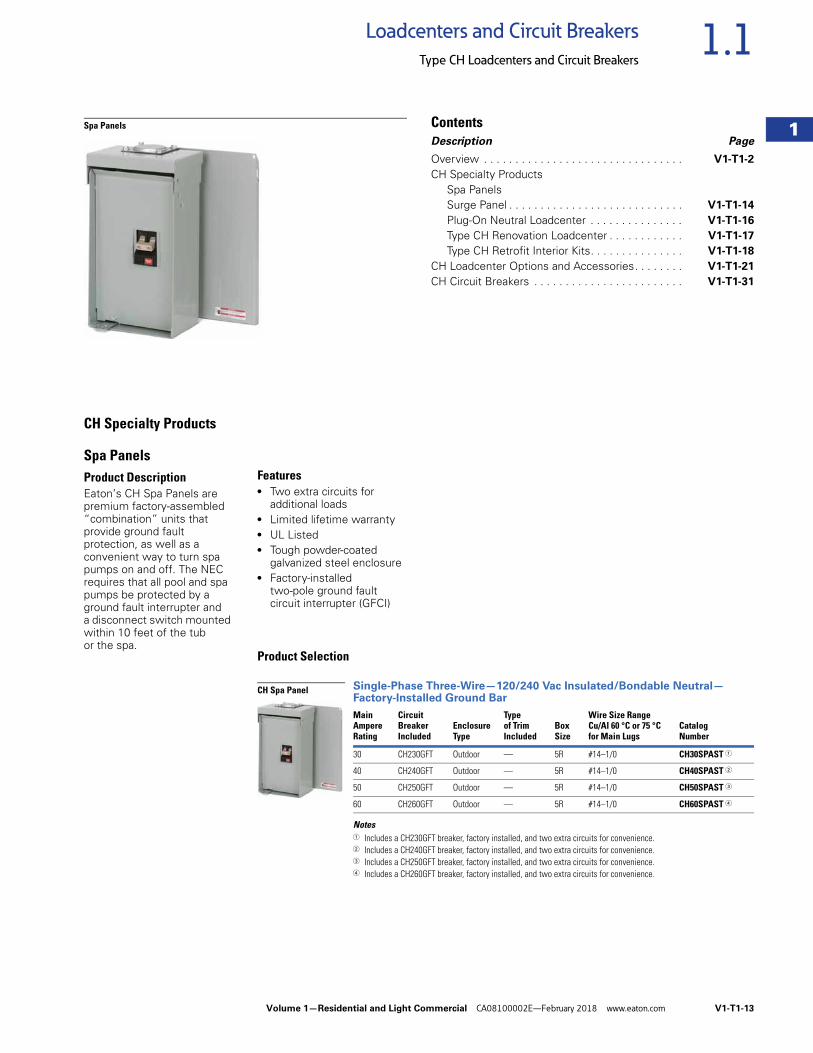
Spa PanelsProduct DescriptionEaton’s CH Spa Panels are premium factory-assembled “combination” units that provide ground fault protection, as well as a convenient way to turn spa pumps on and off. The NEC requires that all pool and spa pumps be protected by a ground fault interrupter and a disconnect switch mounted within 10 feet of the tub or the spa.
Features● Two extra circuits for
additional loads ● Limited lifetime warranty ● UL Listed ● Tough powder-coated
galvanized steel enclosure ● Factory-installed
two-pole ground fault circuit interrupter (GFCI)
Product Selection
Single-Phase Three-Wire—120/240 Vac Insulated/Bondable Neutral—Factory-Installed Ground Bar
Notes1 Includes a CH230GFT breaker, factory installed, and two extra circuits for convenience.2 Includes a CH240GFT breaker, factory installed, and two extra circuits for convenience.3 Includes a CH250GFT breaker, factory installed, and two extra circuits for convenience.4 Includes a CH260GFT breaker, factory installed, and two extra circuits for convenience.
MainAmpere Rating
Circuit BreakerIncluded
EnclosureType
Type of Trim Included
Box Size
Wire Size Range Cu/Al 60 °C or 75 °C for Main Lugs
Catalog Number
30 CH230GFT Outdoor — 5R #14–1/0 CH30SPAST 1
40 CH240GFT Outdoor — 5R #14–1/0 CH40SPAST 2
50 CH250GFT Outdoor — 5R #14–1/0 CH50SPAST 3
60 CH260GFT Outdoor — 5R #14–1/0 CH60SPAST 4
CH Spa Panel
V1-T1-14 Volume 1—Residential and Light Commercial CA08100002E—February 2018 www.eaton.com
1
1
1
1
1
1
1
1
1
1
1
1
1
1
1
1
1
1
1
1
1
1
1
1
1
1
1
1
1
1
1.1 Loadcenters and Circuit Breakers
Type CH Loadcenters and Circuit Breakers
Surge Panel ContentsDescription Page
Overview . . . . . . . . . . . . . . . . . . . . . . . . . . . . . . . . V1-T1-2
CH Specialty ProductsSpa Panels . . . . . . . . . . . . . . . . . . . . . . . . . . . . V1-T1-13
Surge PanelPlug-On Neutral Loadcenter . . . . . . . . . . . . . . . V1-T1-16
Type CH Renovation Loadcenter. . . . . . . . . . . . V1-T1-17
Type CH Retrofit Interior Kits . . . . . . . . . . . . . . V1-T1-18
CH Loadcenter Options and Accessories . . . . . . . V1-T1-21
CH Circuit Breakers . . . . . . . . . . . . . . . . . . . . . . . . V1-T1-31
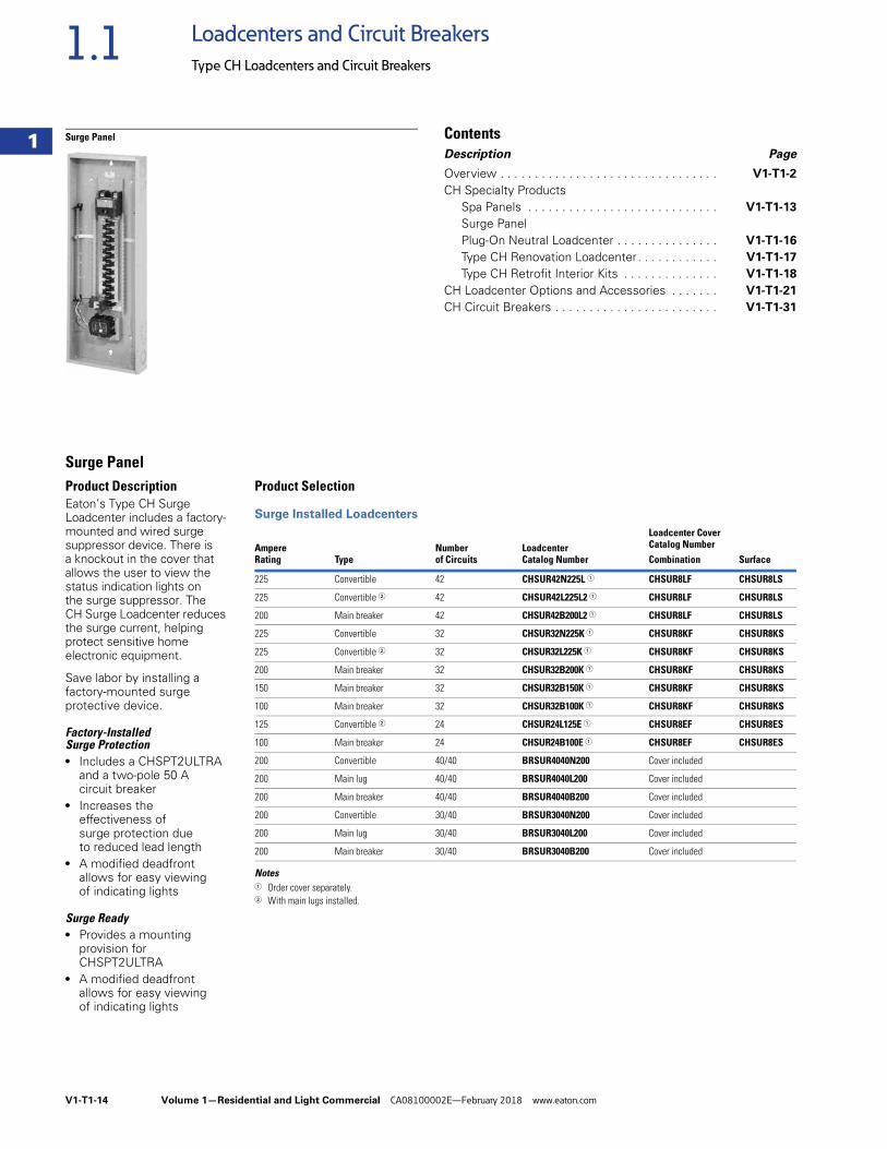
Surge PanelProduct DescriptionEaton’s Type CH Surge Loadcenter includes a factory-mounted and wired surge suppressor device. There is a knockout in the cover that allows the user to view the status indication lights on the surge suppressor. The CH Surge Loadcenter reduces the surge current, helping protect sensitive home electronic equipment.
Save labor by installing a factory-mounted surge protective device.
Factory-Installed Surge Protection● Includes a CHSPT2ULTRA
and a two-pole 50 A circuit breaker
● Increases the effectiveness of surge protection due to reduced lead length
● A modified deadfront allows for easy viewing of indicating lights
Surge Ready● Provides a mounting
provision for CHSPT2ULTRA
● A modified deadfront allows for easy viewing of indicating lights
Product Selection
Surge Installed Loadcenters
Notes1 Order cover separately.2 With main lugs installed.
Ampere Rating Type
Number of Circuits
LoadcenterCatalog Number
Loadcenter Cover Catalog NumberCombination Surface
225 Convertible 42 CHSUR42N225L 1 CHSUR8LF CHSUR8LS
225 Convertible 2 42 CHSUR42L225L2 1 CHSUR8LF CHSUR8LS
200 Main breaker 42 CHSUR42B200L2 1 CHSUR8LF CHSUR8LS
225 Convertible 32 CHSUR32N225K 1 CHSUR8KF CHSUR8KS
225 Convertible 2 32 CHSUR32L225K 1 CHSUR8KF CHSUR8KS
200 Main breaker 32 CHSUR32B200K 1 CHSUR8KF CHSUR8KS
150 Main breaker 32 CHSUR32B150K 1 CHSUR8KF CHSUR8KS
100 Main breaker 32 CHSUR32B100K 1 CHSUR8KF CHSUR8KS
125 Convertible 2 24 CHSUR24L125E 1 CHSUR8EF CHSUR8ES
100 Main breaker 24 CHSUR24B100E 1 CHSUR8EF CHSUR8ES
200 Convertible 40/40 BRSUR4040N200 Cover included
200 Main lug 40/40 BRSUR4040L200 Cover included
200 Main breaker 40/40 BRSUR4040B200 Cover included
200 Convertible 30/40 BRSUR3040N200 Cover included
200 Main lug 30/40 BRSUR3040L200 Cover included
200 Main breaker 30/40 BRSUR3040B200 Cover included
Volume 1—Residential and Light Commercial CA08100002E—February 2018 www.eaton.com V1-T1-15
1
1
1
1
1
1
1
1
1
1
1
1
1
1
1
1
1
1
1
1
1
1
1
1
1
1
1
1
1
1
1.1Loadcenters and Circuit Breakers
Type CH Loadcenters and Circuit Breakers
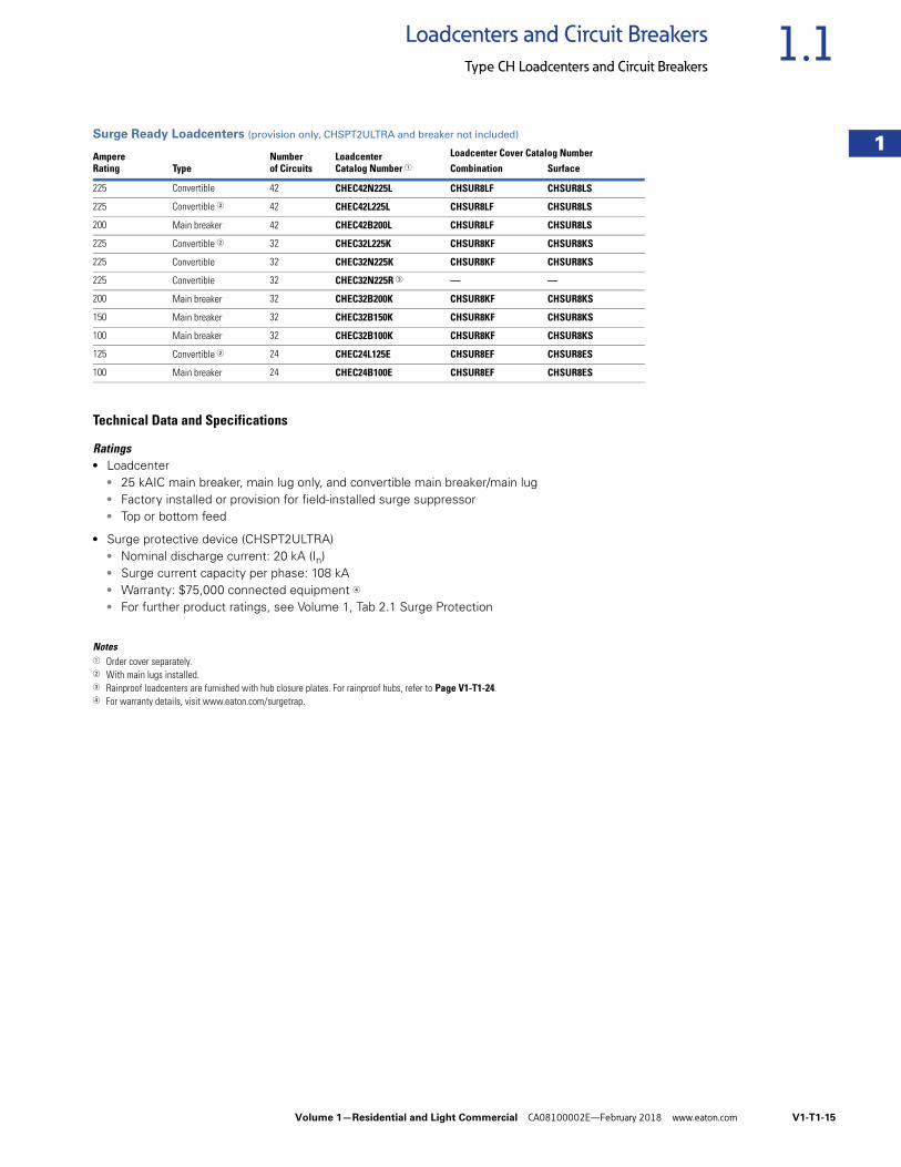
Surge Ready Loadcenters (provision only, CHSPT2ULTRA and breaker not included)
Technical Data and Specifications
Ratings● Loadcenter
● 25 kAIC main breaker, main lug only, and convertible main breaker/main lug● Factory installed or provision for field-installed surge suppressor● Top or bottom feed
● Surge protective device (CHSPT2ULTRA)● Nominal discharge current: 20 kA (In)● Surge current capacity per phase: 108 kA● Warranty: $75,000 connected equipment 4
● For further product ratings, see Volume 1, Tab 2.1 Surge Protection
Notes1 Order cover separately.2 With main lugs installed.3 Rainproof loadcenters are furnished with hub closure plates. For rainproof hubs, refer to Page V1-T1-24.4 For warranty details, visit www.eaton.com/surgetrap.
AmpereRating Type
Number of Circuits
LoadcenterCatalog Number 1
Loadcenter Cover Catalog NumberCombination Surface
225 Convertible 42 CHEC42N225L CHSUR8LF CHSUR8LS
225 Convertible 2 42 CHEC42L225L CHSUR8LF CHSUR8LS
200 Main breaker 42 CHEC42B200L CHSUR8LF CHSUR8LS
225 Convertible 2 32 CHEC32L225K CHSUR8KF CHSUR8KS
225 Convertible 32 CHEC32N225K CHSUR8KF CHSUR8KS
225 Convertible 32 CHEC32N225R 3 — —
200 Main breaker 32 CHEC32B200K CHSUR8KF CHSUR8KS
150 Main breaker 32 CHEC32B150K CHSUR8KF CHSUR8KS
100 Main breaker 32 CHEC32B100K CHSUR8KF CHSUR8KS
125 Convertible 2 24 CHEC24L125E CHSUR8EF CHSUR8ES
100 Main breaker 24 CHEC24B100E CHSUR8EF CHSUR8ES
V1-T1-16 Volume 1—Residential and Light Commercial CA08100002E—February 2018 www.eaton.com
1
1
1
1
1
1
1
1
1
1
1
1
1
1
1
1
1
1
1
1
1
1
1
1
1
1
1
1
1
1
1.1 Loadcenters and Circuit Breakers
Type CH Loadcenters and Circuit Breakers
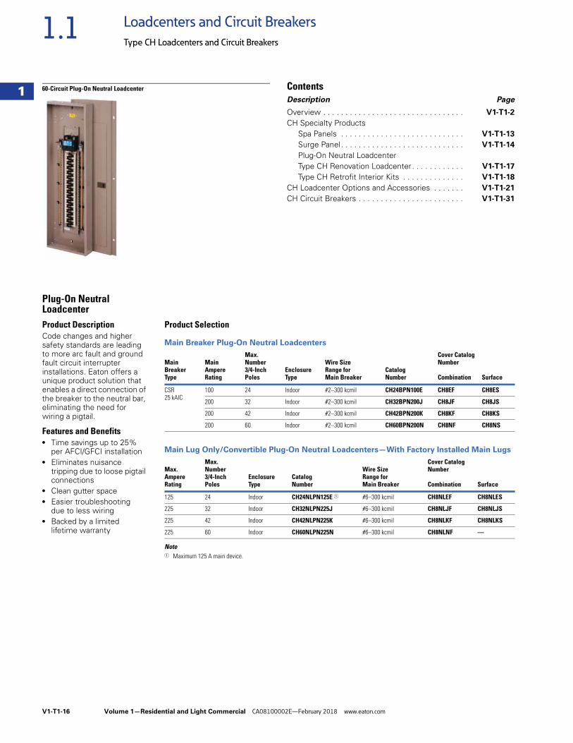
60-Circuit Plug-On Neutral Loadcenter ContentsDescription Page
Overview . . . . . . . . . . . . . . . . . . . . . . . . . . . . . . . . V1-T1-2
CH Specialty ProductsSpa Panels . . . . . . . . . . . . . . . . . . . . . . . . . . . . V1-T1-13
Surge Panel. . . . . . . . . . . . . . . . . . . . . . . . . . . . V1-T1-14
Plug-On Neutral LoadcenterType CH Renovation Loadcenter. . . . . . . . . . . . V1-T1-17
Type CH Retrofit Interior Kits . . . . . . . . . . . . . . V1-T1-18
CH Loadcenter Options and Accessories . . . . . . . V1-T1-21
CH Circuit Breakers . . . . . . . . . . . . . . . . . . . . . . . . V1-T1-31
Plug-On Neutral LoadcenterProduct DescriptionCode changes and higher safety standards are leading to more arc fault and ground fault circuit interrupter installations. Eaton offers a unique product solution that enables a direct connection of the breaker to the neutral bar, eliminating the need for wiring a pigtail.
Features and Benefits● Time savings up to 25%
per AFCI/GFCI installation● Eliminates nuisance
tripping due to loose pigtail connections
● Clean gutter space● Easier troubleshooting
due to less wiring● Backed by a limited
lifetime warranty
Product Selection
Main Breaker Plug-On Neutral Loadcenters
Main Lug Only/Convertible Plug-On Neutral Loadcenters—With Factory Installed Main Lugs
Note1 Maximum 125 A main device.
MainBreakerType
MainAmpereRating
Max.Number3/4-InchPoles
EnclosureType
Wire SizeRange forMain Breaker
CatalogNumber
Cover Catalog Number
Combination Surface
CSR 25 kAIC
100 24 Indoor #2–300 kcmil CH24BPN100E CH8EF CH8ES
200 32 Indoor #2–300 kcmil CH32BPN200J CH8JF CH8JS
200 42 Indoor #2–300 kcmil CH42BPN200K CH8KF CH8KS
200 60 Indoor #2–300 kcmil CH60BPN200N CH8NF CH8NS
Max.AmpereRating
Max.Number3/4-InchPoles
EnclosureType
CatalogNumber
Wire SizeRange for Main Breaker
Cover CatalogNumber
Combination Surface
125 24 Indoor CH24NLPN125E 1 #6–300 kcmil CH8NLEF CH8NLES
225 32 Indoor CH32NLPN225J #6–300 kcmil CH8NLJF CH8NLJS
225 42 Indoor CH42NLPN225K #6–300 kcmil CH8NLKF CH8NLKS
225 60 Indoor CH60NLPN225N #6–300 kcmil CH8NLNF —
Volume 1—Residential and Light Commercial CA08100002E—February 2018 www.eaton.com V1-T1-17
1
1
1
1
1
1
1
1
1
1
1
1
1
1
1
1
1
1
1
1
1
1
1
1
1
1
1
1
1
1
1.1Loadcenters and Circuit Breakers
Type CH Loadcenters and Circuit Breakers
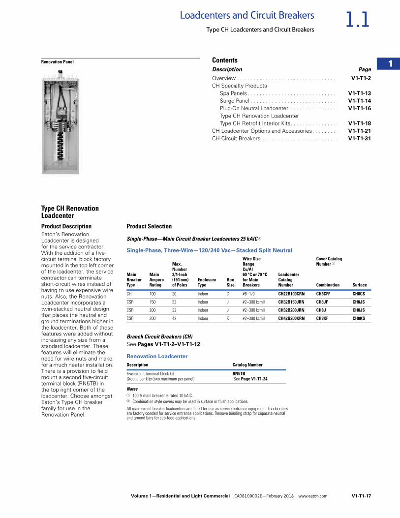
Renovation Panel ContentsDescription Page
Overview . . . . . . . . . . . . . . . . . . . . . . . . . . . . . . . . V1-T1-2
CH Specialty ProductsSpa Panels. . . . . . . . . . . . . . . . . . . . . . . . . . . . . V1-T1-13
Surge Panel . . . . . . . . . . . . . . . . . . . . . . . . . . . . V1-T1-14
Plug-On Neutral Loadcenter . . . . . . . . . . . . . . . V1-T1-16
Type CH Renovation LoadcenterType CH Retrofit Interior Kits. . . . . . . . . . . . . . . V1-T1-18
CH Loadcenter Options and Accessories. . . . . . . . V1-T1-21
CH Circuit Breakers . . . . . . . . . . . . . . . . . . . . . . . . V1-T1-31
Type CH Renovation LoadcenterProduct DescriptionEaton’s Renovation Loadcenter is designed for the service contractor. With the addition of a five-circuit terminal block factory mounted in the top left corner of the loadcenter, the service contractor can terminate short-circuit wires instead of having to use expensive wire nuts. Also, the Renovation Loadcenter incorporates a twin-stacked neutral design that places the neutral and ground terminations higher in the loadcenter. Both of these features were added without increasing any size from a standard loadcenter. These features will eliminate the need for wire nuts and make for a much neater installation. There is a provision to field mount a second five-circuit terminal block (RN5TB) in the top right corner of the loadcenter. Choose amongst Eaton’s Type CH breaker family for use in the Renovation Panel.
Product Selection
Single-Phase—Main Circuit Breaker Loadcenters 25 kAIC 1
Single-Phase, Three-Wire—120/240 Vac—Stacked Split Neutral
Branch Circuit Breakers (CH)See Pages V1-T1-2–V1-T1-12.
Renovation Loadcenter
Notes1 100 A main breaker is rated 10 kAIC.2 Combination style covers may be used in surface or flush applications.
All main circuit breaker loadcenters are listed for use as service entrance equipment. Loadcenters are factory-bonded for service entrance applications. Remove bonding strap for separate neutral and ground bars for sub-feed applications.
MainBreakerType
MainAmpereRating
Max.Number3/4-Inch(19.1 mm)of Poles
EnclosureType
BoxSize
Wire SizeRangeCu/Al60 °C or 70 °Cfor MainBreakers
LoadcenterCatalogNumber
Cover CatalogNumber 2
Combination Surface
CH 100 20 Indoor C #6–1/0 CH22B100CRN CH8CFF CH8CS
CSR 150 32 Indoor J #2–300 kcmil CH32B150JRN CH8JF CH8JS
CSR 200 32 Indoor J #2–300 kcmil CH32B200JRN CH8J CH8JS
CSR 200 42 Indoor K #2–300 kcmil CH42B200KRN CH8KF CH8KS
Description Catalog Number
Five-circuit terminal block kitGround bar kits (two maximum per panel)
RN5TB(See Page V1-T1-24)
V1-T1-18 Volume 1—Residential and Light Commercial CA08100002E—February 2018 www.eaton.com
1
1
1
1
1
1
1
1
1
1
1
1
1
1
1
1
1
1
1
1
1
1
1
1
1
1
1
1
1
1
1.1 Loadcenters and Circuit Breakers
Type CH Loadcenters and Circuit Breakers
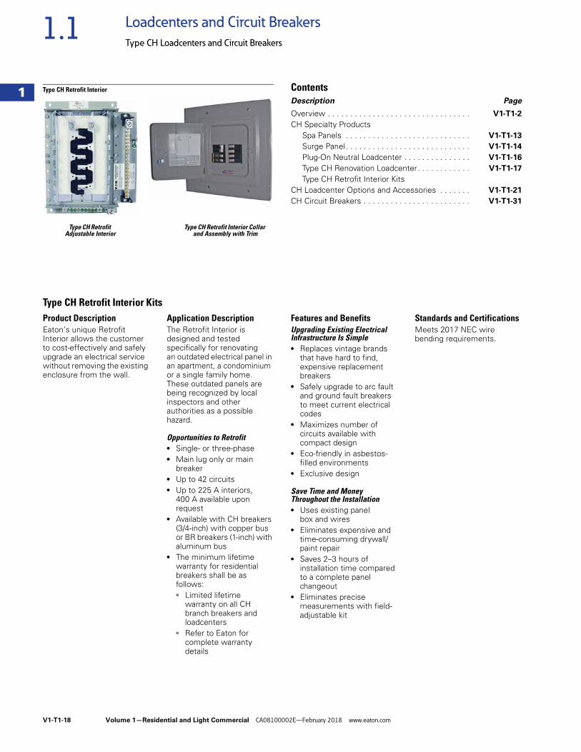
Type CH Retrofit Type CH Retrofit Interior Collar Adjustable Interior and Assembly with Trim
Type CH Retrofit Interior ContentsDescription Page
Overview . . . . . . . . . . . . . . . . . . . . . . . . . . . . . . . . V1-T1-2
CH Specialty ProductsSpa Panels . . . . . . . . . . . . . . . . . . . . . . . . . . . . V1-T1-13
Surge Panel. . . . . . . . . . . . . . . . . . . . . . . . . . . . V1-T1-14
Plug-On Neutral Loadcenter . . . . . . . . . . . . . . . V1-T1-16
Type CH Renovation Loadcenter. . . . . . . . . . . . V1-T1-17
Type CH Retrofit Interior KitsCH Loadcenter Options and Accessories . . . . . . . V1-T1-21
CH Circuit Breakers . . . . . . . . . . . . . . . . . . . . . . . . V1-T1-31
Type CH Retrofit Interior KitsProduct DescriptionEaton’s unique Retrofit Interior allows the customer to cost-effectively and safely upgrade an electrical service without removing the existing enclosure from the wall.
Application DescriptionThe Retrofit Interior is designed and tested specifically for renovating an outdated electrical panel in an apartment, a condominium or a single family home. These outdated panels are being recognized by local inspectors and other authorities as a possible hazard.
Opportunities to Retrofit● Single- or three-phase● Main lug only or main
breaker● Up to 42 circuits● Up to 225 A interiors,
400 A available upon request
● Available with CH breakers (3/4-inch) with copper bus or BR breakers (1-inch) with aluminum bus
● The minimum lifetime warranty for residential breakers shall be as follows:● Limited lifetime
warranty on all CH branch breakers and loadcenters
● Refer to Eaton for complete warranty details
Features and BenefitsUpgrading Existing Electrical Infrastructure Is Simple● Replaces vintage brands
that have hard to find, expensive replacement breakers
● Safely upgrade to arc fault and ground fault breakers to meet current electrical codes
● Maximizes number of circuits available with compact design
● Eco-friendly in asbestos-filled environments
● Exclusive design
Save Time and Money Throughout the Installation● Uses existing panel
box and wires● Eliminates expensive and
time-consuming drywall/paint repair
● Saves 2–3 hours of installation time compared to a complete panel changeout
● Eliminates precise measurements with field-adjustable kit
Standards and CertificationsMeets 2017 NEC wire bending requirements.
Volume 1—Residential and Light Commercial CA08100002E—February 2018 www.eaton.com V1-T1-19
1
1
1
1
1
1
1
1
1
1
1
1
1
1
1
1
1
1
1
1
1
1
1
1
1
1
1
1
1
1
1.1Loadcenters and Circuit Breakers
Type CH Loadcenters and Circuit Breakers
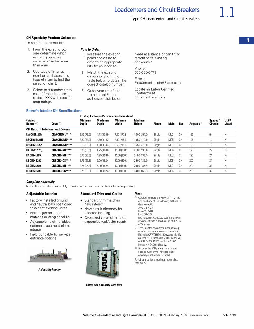
CH Specialty Product SelectionTo select the retrofit kit:
1. From the existing box size determine which retrofit groups are suitable (may be more than one).
2. Use type of interior, number of phases, and type of main to find the selection chart.
3. Select part number from chart (if main breaker, replace XXX with specific amp rating).
How to Order:1. Measure the existing
panel enclosure to determine appropriate kits for your project.
2. Match the existing dimensions with the table below to obtain the correct catalog number.
3. Order your retrofit kit from a local Eaton authorized distributor.
Need assistance or can’t find retrofit to fit existing enclosure?
Phone:800-330-6479
E-mail:[email protected]
Locate an Eaton Certified Contractor at EatonCertified.com
Retrofit Interior Kit Specifications
Complete AssemblyNote: For complete assembly, interior and cover need to be ordered separately.
Adjustable Interior
● Factory installed ground and neutral bars positioned to accept existing wires
● Field adjustable depth matches existing panel box
● Adjustable height enables optional placement of the interior
● Field bondable for service entrance options
Adjustable Interior
Standard Trim and Collar
● Standard trim matches new interior
● New circuit directory for updated labeling
● Oversized collar eliminates expensive wall/paint repair
Collar and Assembly with Trim
Notes1 Catalog numbers shown with “_” at the
end need one of the following suffixes to denote depth:J = 3.75–4.25K = 4.25–5.00L = 5.00–6.00Example: RBCH24B200J would signify an interior set with a depth range of 3.75 to 4.25 inches.
2 ****Denotes characters in the catalog number that relate to overall cover size.Example: CRWCH6ML2620 would signify a cover 26.00 inches H x 20.00 inches W, or CRBCH24CS3324 would be 33.00 inches H x 24.00 inches W.
3 Amperes for MB panels is maximum; catalog number will reflect actual amperage of breaker included.
For UL applications, maximum cover sizes may apply.
Existing Enclosure Parameters—Inches (mm)Catalog Number 1 Cover 2
MinimumDepth
MaximumDepth
MinimumWidth
MinimumHeight Phase Main Bus Amperes 3
Spaces / Circuits
UL 67 Listed
CH Retrofit Interiors and Covers
RWCH6L125N CRWCH6ML**** 3.13 (79.5) 4.13 (104.9) 7.00 (177.8) 10.00 (254.0) Single MLO CH 125 6 No
RSCH10B125N CRWCH12ML**** 3.50 (88.9) 4.50 (114.3) 8.50 (215.9) 16.50 (419.1) Single MCB CH 125 10 No
RSCH12L125N CRWCH12ML**** 3.50 (88.9) 4.50 (114.3) 8.50 (215.9) 16.50 (419.1) Single MLO CH 125 12 No
RACH22B125_ CRACH24ML**** 3.75 (95.3) 4.25 (108.0) 13.00 (330.2) 21.00 (533.4) Single MCB CH 125 22 No
RACH24L125_ CRACH24ML**** 3.75 (95.3) 4.25 (108.0) 13.00 (330.2) 21.00 (533.4) Single MLO CH 125 24 No
RBCH24B200_ CRBCH24CS**** 3.75 (95.3) 6.00 (152.4) 13.00 (330.2) 29.00 (736.6) Single MCB CH 200 24 No
RBCH32L200_ CRBCH32ML**** 3.75 (95.3) 6.00 (152.4) 13.00 (330.2) 29.00 (736.6) Single MLO CH 200 32 No
RCCH32B200_ CRBCH32CS**** 3.75 (95.3) 6.00 (152.4) 13.00 (330.2) 34.00 (863.6) Single MCB CH 200 32 No
V1-T1-20 Volume 1—Residential and Light Commercial CA08100002E—February 2018 www.eaton.com
1
1
1
1
1
1
1
1
1
1
1
1
1
1
1
1
1
1
1
1
1
1
1
1
1
1
1
1
1
1
1.1 Loadcenters and Circuit Breakers
Type CH Loadcenters and Circuit Breakers
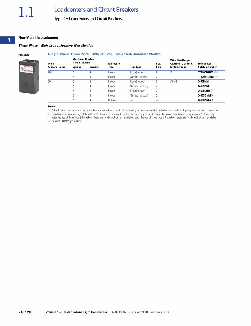
Non-Metallic Loadcenter
Single-Phase—Main Lug Loadcenters, Non-Metallic
Single-Phase Three-Wire—120/240 Vac—Insulated/Bondable Neutral
Notes1 Suitable for use as service equipment when not more than six main disconnecting means are provided and when not used as a lighting and appliance panelboard.2 This device has no main lugs. A Type BR or BD breaker is required to be backfed to supply power to branch breakers. This device is single-phase 120 Vac only.
With the use of three Type BR breakers, there are two branch circuits available. With the use of three Type BD breakers, there are five branch circuits available.3 Includes GB4NM ground bar.
Is this the correct location for this table?
MainAmpere Rating
Maximum Number1-Inch (25.4 mm) Enclosure
Type Trim TypeBoxSize
Wire Size Range Cu/Al 60 °C or 75 °C for Main Lugs
LoadcenterCatalog NumberSpaces Circuits
40 1 2 4 Indoor Flush (no door) 2 2 TT120FLGNM 23
2 4 Indoor Surface (no door) 2 TT120SLGNM 23
60 2 4 Indoor Flush (no door) 2 #14–2 2460FNM
2 4 Indoor Surface (no door) 2 2460SNM
2 4 Indoor Flush (no door) 2 2460FGNM 3
2 4 Indoor Surface (no door) 2 2460SGNM 3
2 4 Outdoor — — 2460RNM-A2
2460SNM
Volume 1—Residential and Light Commercial CA08100002E—February 2018 www.eaton.com V1-T1-21
1
1
1
1
1
1
1
1
1
1
1
1
1
1
1
1
1
1
1
1
1
1
1
1
1
1
1
1
1
1
1.1Loadcenters and Circuit Breakers
Type CH Loadcenters and Circuit Breakers
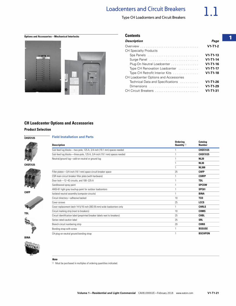
Options and Accessories—Mechanical Interlocks ContentsDescription Page
Overview . . . . . . . . . . . . . . . . . . . . . . . . . . . . . . . . V1-T1-2
CH Specialty ProductsSpa Panels . . . . . . . . . . . . . . . . . . . . . . . . . . . . V1-T1-13
Surge Panel . . . . . . . . . . . . . . . . . . . . . . . . . . . V1-T1-14
Plug-On Neutral Loadcenter . . . . . . . . . . . . . . . V1-T1-16
Type CH Renovation Loadcenter . . . . . . . . . . . V1-T1-17
Type CH Retrofit Interior Kits . . . . . . . . . . . . . . V1-T1-18
CH Loadcenter Options and AccessoriesTechnical Data and Specifications . . . . . . . . . . V1-T1-26
Dimensions . . . . . . . . . . . . . . . . . . . . . . . . . . . V1-T1-29
CH Circuit Breakers . . . . . . . . . . . . . . . . . . . . . . . . V1-T1-31
CH Loadcenter Options and AccessoriesProduct Selection
Field Installation and Parts
Note1 Must be purchased in multiples of ordering quantities indicated.
DescriptionOrdering Quantity 1
Catalog Number
Sub-feed lug blocks—two-pole, 125 A, 3/4-inch (19.1 mm) spaces needed 1 CHSF2125
Sub-feed lug blocks—three-pole, 125 A, 3/4-inch (19.1 mm) spaces needed 1 CHSF3125
Neutral/ground lug—add-on neutral or ground lug 1 NL20
1 NL30
1 NL300
Filler plates—3/4-inch (19.1 mm) space circuit breaker space 25 CHFP
CSR main circuit breaker filler plate (with hardware) 1 CSRFP
Door lock—12–42 circuits, and 100–225 A 1 TDL
Sandlewood spray paint 1 SPCSW
ANSI-61 light gray touchup paint for outdoor loadcenters 1 SPC61
Isolated neutral assembly (computer circuits) 1 BINA
Circuit directory—adhesive backed 10 TCD
Cover screws 25 LCCS
Cover replacement latch 14-5/16 inch (363.55 mm) wide loadcenters only 1 CHRLS
Circuit marking strip (next to breakers) 10 CHMS
Circuit identification label (preprinted breaker labels next to breakers) 25 CHBL
Series rated caution label 25 SRL
Branch circuit numbering strip 20 CHNS
Bonding strap with screw 1 BSSUSE
CH plug-on neutral ground bonding strap 1 BSCHPON
CHSF2125
CHSF3125
CHFP
TDL
BINA
V1-T1-22 Volume 1—Residential and Light Commercial CA08100002E—February 2018 www.eaton.com
1
1
1
1
1
1
1
1
1
1
1
1
1
1
1
1
1
1
1
1
1
1
1
1
1
1
1
1
1
1
1.1 Loadcenters and Circuit Breakers
Type CH Loadcenters and Circuit Breakers
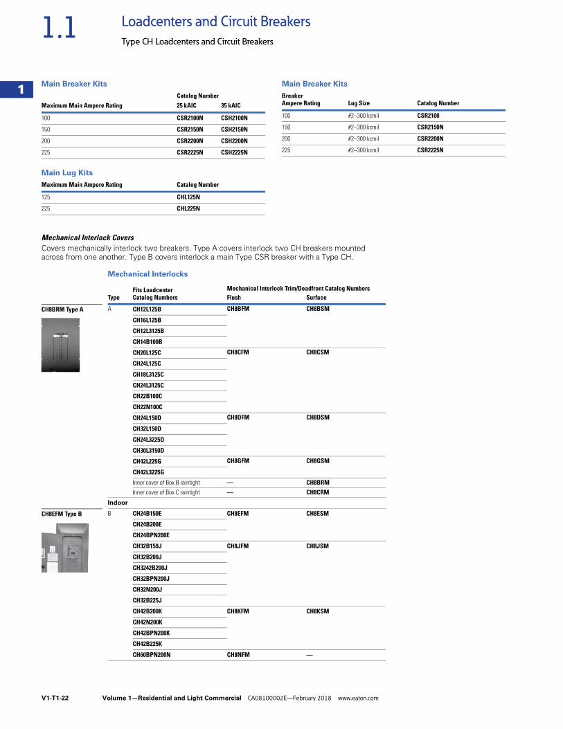
Main Breaker Kits
Main Lug Kits
Main Breaker Kits
Mechanical Interlock CoversCovers mechanically interlock two breakers. Type A covers interlock two CH breakers mounted across from one another. Type B covers interlock a main Type CSR breaker with a Type CH.
Mechanical Interlocks
Maximum Main Ampere RatingCatalog Number25 kAIC 35 kAIC
100 CSR2100N CSH2100N
150 CSR2150N CSH2150N
200 CSR2200N CSH2200N
225 CSR2225N CSH2225N
Maximum Main Ampere Rating Catalog Number
125 CHL125N
225 CHL225N
Breaker Ampere Rating Lug Size Catalog Number
100 #2–300 kcmil CSR2100
150 #2–300 kcmil CSR2150N
200 #2–300 kcmil CSR2200N
225 #2–300 kcmil CSR2225N
Fits LoadcenterCatalog Numbers
Mechanical Interlock Trim/Deadfront Catalog NumbersType Flush Surface
A CH12L125B CH8BFM CH8BSM
CH16L125B
CH12L3125B
CH14B100B
CH20L125C CH8CFM CH8CSM
CH24L125C
CH18L3125C
CH24L3125C
CH22B100C
CH22N100C
CH24L150D CH8DFM CH8DSM
CH32L150D
CH24L3225D
CH30L3150D
CH42L225G CH8GFM CH8GSM
CH42L3225G
Inner cover of Box B raintight — CH8BRM
Inner cover of Box C raintight — CH8CRM
Indoor
B CH24B150E CH8EFM CH8ESM
CH24B200E
CH24BPN200E
CH32B150J CH8JFM CH8JSM
CH32B200J
CH3242B200J
CH32BPN200J
CH32N200J
CH32B225J
CH42B200K CH8KFM CH8KSM
CH42N200K
CH42BPN200K
CH42B225K
CH60BPN200N CH8NFM —
CH8BRM Type A
CH8EFM Type B
Volume 1—Residential and Light Commercial CA08100002E—February 2018 www.eaton.com V1-T1-23
1
1
1
1
1
1
1
1
1
1
1
1
1
1
1
1
1
1
1
1
1
1
1
1
1
1
1
1
1
1
1.1Loadcenters and Circuit Breakers
Type CH Loadcenters and Circuit Breakers
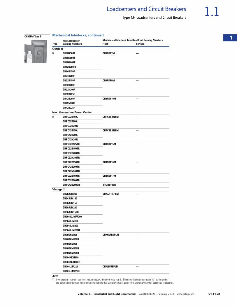
Mechanical Interlocks, continued
Note1 If vintage part number does not match exactly, the cover may not fit. Simple variations such as an “N” at the end of
the part number contain minor design variations that will prevent our cover from working with that particular loadcenter.
TypeFits LoadcenterCatalog Numbers
Mechanical Interlock Trim/Deadfront Catalog NumbersFlush Surface
Outdoor
B CH8B150RF CH3RDF7M —
CH8B200RF
CH8N200RF
CH12B200RF
CH24B150R
CH24B200R
CH32B150R CH3RDF9M —
CH32B200R
CH32N200R
CH32B225R
CH42B200R CH3RDF10M —
CH42N200R
CH42B225R
Next Generation Power Center
B CHPC32B150L CHPC8B32LFM —
CHPC32B200L
CHPC32N200L
CHPC42B150L CHPC8B42LFM —
CHPC42B200L
CHPC42N200L
CHPC32B125TR CH3RDF15M —
CHPC32B150TR
CHPC32B200TR
CHPC32N200TR
CHPC42B150TR CH3RDF16M —
CHPC42B200TR
CHPC42N200TR
CHPC32B150TR CH3RDF17M —
CHPC32B200TR
CHPC42B200BR CH3RDF18M —
Vintage 1
CH20JJM200 CH7JJFREPLM —
CH24JJM150
CH30JJM150
CH30JJM200
CH30JJM150H
CH3040JJMM200
CH304JJM150
CH304JJM200
CH304JJM200H
CH30KKM225 CH7KKFREPLM —
CH40KKM200H
CH40KKM225
CH40KKM200H
CH40KKM225H
CH304KKM200
CH304KKM200H
CH304LLM225 CH7LLFREPLM —
CH424LLM225H
CH8EFM Type B
V1-T1-24 Volume 1—Residential and Light Commercial CA08100002E—February 2018 www.eaton.com
1
1
1
1
1
1
1
1
1
1
1
1
1
1
1
1
1
1
1
1
1
1
1
1
1
1
1
1
1
1
1.1 Loadcenters and Circuit Breakers
Type CH Loadcenters and Circuit Breakers
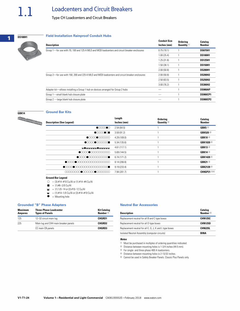
Field Installation Rainproof Conduit Hubs
Ground Bar Kits
Ground Bar Legend
Grounded “B” Phase Adapters Neutral Bar Accessories
Notes1 Must be purchased in multiples of ordering quantities indicated.2 Distance between mounting holes is 1-3/4 inches (44.5 mm).3 For single- and three-phase 400 A loadcenters.4 Distance between mounting holes is 2-13/32 inches.5 Cannot be used in Safety Breaker Panels. Classic Plus Panels only.
DescriptionConduit Size Ordering
Quantity 1CatalogNumberInches (mm)
Group 1—for use with 70, 100 and 125 A MLO and MCB loadcenters and circuit breaker enclosures 0.75 (19.1) 1 DS075H1
1.00 (25.4) 1 DS100H1
1.25 (31.8) 1 DS125H1
1.50 (38.1) 1 DS150H1
2.00 (50.8) 1 DS200H1
Group 2—for use with 150, 200 and 225 A MLO and MCB loadcenters and circuit breaker enclosures 2.00 (50.8) 1 DS200H2
2.50 (63.5) 1 DS250H2
3.00 (76.2) 1 DS300H2
Adapter kit—allows installing a Group 1 hub on devices arranged for Group 2 hubs — 1 DS900AP
Group 1—small blank hub closure plate — 1 DS900CP1
Group 2 —large blank hub closure plate — 1 DS900CP2
Description (See Legend)Length Ordering
Quantity 2Catalog NumberInches (mm)
dssssds 2.54 (64.5) 1 GBK5 2
dssssdsj 3.59 (91.2) 1 GBK520 2
dssssdssssss 4.29 (109.0) 1 GBK10 2
dssssdssssssj 5.34 (135.6) 1 GBK1020 2
4.61 (117.1) 1 GBK13 2
dssssdssssssssss 5.69 (144.5) 1 GBK14 2
dssssdssssssssssj 6.74 (171.2) 1 GBK1420 2
dssssdsssssssssssssssss 8.14 (206.8) 1 GBK21 2
dssssdsssssssssssssssssj 9.19 (233.4) 1 GBK2120 2
ssssssssdssssssdsssssss 7.94 (201.7) 1 CH9GP21 34
DS100H1
GBK14
f d f f f k f d f k f f f
s
j
d
= (3) #14–#10 Cu/Al or (1) #14–#4 Cu/Al= (1) #6–2/0 Cu/Al= (1) 1/0–14 or (3) #10–12 Cu/Al= (1) #14–1/0 Cu/Al or (3) #14–#10 Cu/Al= Mounting hole
f k
MaximumAmperes
Three-Phase LoadcenterTypes of Panels
Kit CatalogNumber 5
125 12–32 circuit main lug CHGRD1
225 Main lug and CHH main breaker panels CHGRD2
CC main CB panels CHGRD3
DescriptionCatalogNumber 5
Replacement neutral for all B and C type boxes CHN125C
Replacement neutral for all D type boxes CHN125D
Replacement neutral for all E, G, J, K and L type boxes CHN225L
Isolated Neutral Assembly (computer circuits) BINA
Volume 1—Residential and Light Commercial CA08100002E—February 2018 www.eaton.com V1-T1-25
1
1
1
1
1
1
1
1
1
1
1
1
1
1
1
1
1
1
1
1
1
1
1
1
1
1
1
1
1
1
1.1Loadcenters and Circuit Breakers
Type CH Loadcenters and Circuit Breakers
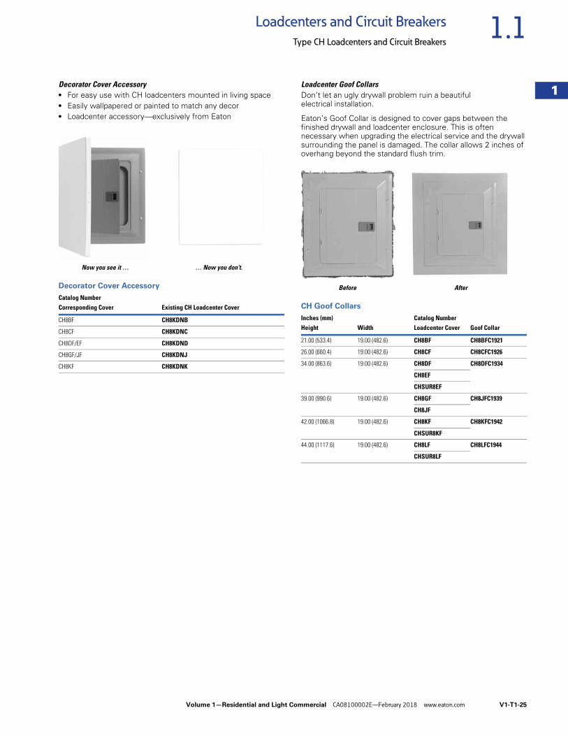
Decorator Cover Accessory● For easy use with CH loadcenters mounted in living space● Easily wallpapered or painted to match any decor● Loadcenter accessory—exclusively from Eaton
Now you see it … … Now you don’t.
Decorator Cover Accessory
Loadcenter Goof CollarsDon’t let an ugly drywall problem ruin a beautiful electrical installation.
Eaton’s Goof Collar is designed to cover gaps between the finished drywall and loadcenter enclosure. This is often necessary when upgrading the electrical service and the drywall surrounding the panel is damaged. The collar allows 2 inches of overhang beyond the standard flush trim.
Before After
CH Goof CollarsCatalog NumberCorresponding Cover Existing CH Loadcenter Cover
CH8BF CH8KDNB
CH8CF CH8KDNC
CH8DF/EF CH8KDND
CH8GF/JF CH8KDNJ
CH8KF CH8KDNK
Inches (mm) Catalog NumberHeight Width Loadcenter Cover Goof Collar
21.00 (533.4) 19.00 (482.6) CH8BF CH8BFC1921
26.00 (660.4) 19.00 (482.6) CH8CF CH8CFC1926
34.00 (863.6) 19.00 (482.6) CH8DF CH8DFC1934
CH8EF
CHSUR8EF
39.00 (990.6) 19.00 (482.6) CH8GF CH8JFC1939
CH8JF
42.00 (1066.8) 19.00 (482.6) CH8KF CH8KFC1942
CHSUR8KF
44.00 (1117.6) 19.00 (482.6) CH8LF CH8LFC1944
CHSUR8LF
SCOTTHAS
PHOTO
V1-T1-26 Volume 1—Residential and Light Commercial CA08100002E—February 2018 www.eaton.com
1
1
1
1
1
1
1
1
1
1
1
1
1
1
1
1
1
1
1
1
1
1
1
1
1
1
1
1
1
1
1.1 Loadcenters and Circuit Breakers
Type CH Loadcenters and Circuit Breakers
Technical Data and Specifications
GeneralA. The Contractor shall
furnish and install loadcenters incorporating circuit breakers of the number, rating and type as specified herein and as shown on the contract drawings.
B. The loadcenter and all components shall be designed, manufactured and tested in accordance with the latest applicable standards of UL and NEMA including:
1. UL 67—standards for panelboards
2. UL 50—standards for cabinets and boxes
3. UL 489—standards for molded case circuit breakers
4. Federal Spec Classification W-C 375
5. UL 1699—all fault interrupting
QualificationsA. The manufacturer of the
loadcenter shall be the manufacturer of the circuit breaker within the load center. All breakers shall be full size.
B. For the equipment specified herein, the manufacturer shall be ISO® 9000 certified.
C. The manufacturer of this equipment shall have produced similar electrical equipment for a minimum period of seven (7) years.
ManufacturersA. Eaton
RatingsA. Loadcenters shall be
rated for 240 Vac and shall have short-circuit ratings as shown on the drawings or as herein scheduled, but not less than 10,000 amperes rms symmetrical.
B. Breakers shall be full size and a minimum of 125 A frame. Breakers 10 –125 A trip size shall take up the same pole spacing.
C. Loadcenters shall be labeled with a UL short-circuit rating. When series ratings are applied with integral or remote devices, a label shall be provided. Series ratings shall cover all trip ratings of installed frames. It shall state the conditions of the UL series ratings including:
1. Size and type of upstream device.
2. Branch devices that can be used.
3. UL series short-circuit rating.
ConstructionA. All interiors, with the
exception of the branch circuit breakers shall be completely factory assembled with main breakers, main lugs or no main device.
B. Interiors shall be so designed that circuit breakers can be replaced without disturbing adjacent units and without removing the main bus connectors and shall be so designed that circuits may be changed without machining, drilling or tapping.
C. Physical means must be provided to prevent the installation of more overcurrent devices than that number for which the enclosure was designed. Full size breakers are required.
BusA. Busbars for the main and
cross connectors shall be of silver flash plated copper construction in accordance with UL standards. Bussing shall be braced to 65 kAIC.
B. Neutral bussing shall have a suitable lug for each outgoing feeder requiring a neutral connection of same ampacity as branch.
Wiring/TerminationA. All wire connectors and
terminals shall be of the anti-turn solderless type and suitable for copper or aluminum wire of the sizes indicated. All connectors shall meet the “Requirements for Wire Connectors and Soldering Lugs” UL 486B.
B. All loadcenters where marked shall be suitable for use with 60/75 °C rated wire.
Volume 1—Residential and Light Commercial CA08100002E—February 2018 www.eaton.com V1-T1-27
1
1
1
1
1
1
1
1
1
1
1
1
1
1
1
1
1
1
1
1
1
1
1
1
1
1
1
1
1
1
1.1Loadcenters and Circuit Breakers
Type CH Loadcenters and Circuit Breakers
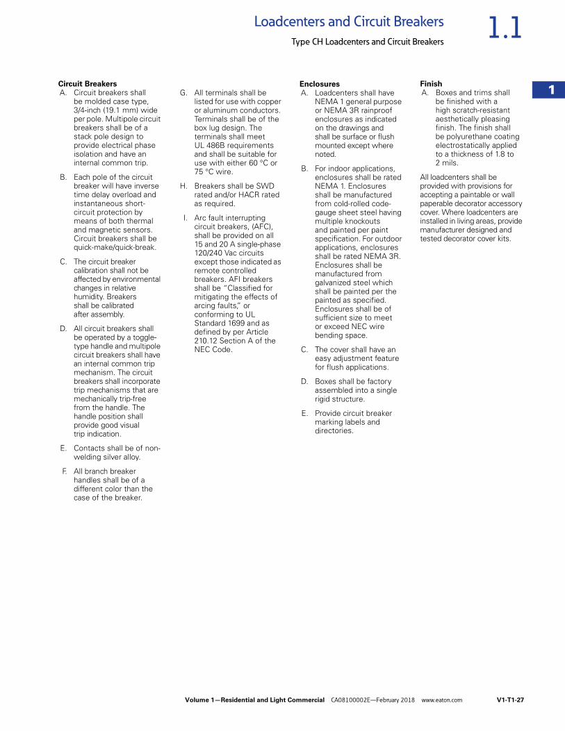
Circuit BreakersA. Circuit breakers shall
be molded case type, 3/4-inch (19.1 mm) wide per pole. Multipole circuit breakers shall be of a stack pole design to provide electrical phase isolation and have an internal common trip.
B. Each pole of the circuit breaker will have inverse time delay overload and instantaneous short-circuit protection by means of both thermal and magnetic sensors. Circuit breakers shall be quick-make/quick-break.
C. The circuit breaker calibration shall not be affected by environmental changes in relative humidity. Breakers shall be calibrated after assembly.
D. All circuit breakers shall be operated by a toggle-type handle and multipole circuit breakers shall have an internal common trip mechanism. The circuit breakers shall incorporate trip mechanisms that are mechanically trip-free from the handle. The handle position shall provide good visual trip indication.
E. Contacts shall be of non-welding silver alloy.
F. All branch breaker handles shall be of a different color than the case of the breaker.
G. All terminals shall be listed for use with copper or aluminum conductors. Terminals shall be of the box lug design. The terminals shall meet UL 486B requirements and shall be suitable for use with either 60 °C or 75 °C wire.
H. Breakers shall be SWD rated and/or HACR rated as required.
I. Arc fault interrupting circuit breakers, (AFC), shall be provided on all 15 and 20 A single-phase 120/240 Vac circuits except those indicated as remote controlled breakers. AFI breakers shall be “Classified for mitigating the effects of arcing faults,” or conforming to UL Standard 1699 and as defined by per Article 210.12 Section A of the NEC Code.
EnclosuresA. Loadcenters shall have
NEMA 1 general purpose or NEMA 3R rainproof enclosures as indicated on the drawings and shall be surface or flush mounted except where noted.
B. For indoor applications, enclosures shall be rated NEMA 1. Enclosures shall be manufactured from cold-rolled code-gauge sheet steel having multiple knockouts and painted per paint specification. For outdoor applications, enclosures shall be rated NEMA 3R. Enclosures shall be manufactured from galvanized steel which shall be painted per the painted as specified. Enclosures shall be of sufficient size to meet or exceed NEC wire bending space.
C. The cover shall have an easy adjustment feature for flush applications.
D. Boxes shall be factory assembled into a single rigid structure.
E. Provide circuit breaker marking labels and directories.
FinishA. Boxes and trims shall
be finished with a high scratch-resistant aesthetically pleasing finish. The finish shall be polyurethane coating electrostatically applied to a thickness of 1.8 to2 mils.
All loadcenters shall be provided with provisions for accepting a paintable or wall paperable decorator accessory cover. Where loadcenters are installed in living areas, provide manufacturer designed and tested decorator cover kits.
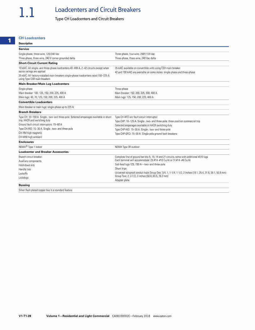
V1-T1-28 Volume 1—Residential and Light Commercial CA08100002E—February 2018 www.eaton.com
1
1
1
1
1
1
1
1
1
1
1
1
1
1
1
1
1
1
1
1
1
1
1
1
1
1
1
1
1
1
1.1 Loadcenters and Circuit Breakers
Type CH Loadcenters and Circuit Breakers
CH Loadcenters
Description
Service
Single-phase, three-wire, 120/240 VacThree-phase, three-wire, 240 V corner grounded delta
Three-phase, four-wire, 208Y/120 VacThree-phase, three-wire, 240 Vac delta
Short-Circuit Current Rating
10 kAIC: All single- and three-phase loadcenters 40–400 A, 2–42 circuits except when series ratings are applied25 kAIC: All factory-installed main breakers single-phase loadcenters rated 150–225 A using Type CSR main breakers
35 kAIC available on convertible units using CSH main breaker42 and 100 kAIC are available on some styles: single-phase and three-phase
Main Breaker/Main Lug Loadcenters
Single-phaseMain breaker: 100, 125, 150, 200, 225, 400 AMain lugs: 40, 70, 125, 150, 200, 225, 400 A
Three-phaseMain breaker: 150, 200, 225, 300, 400 AMain lugs: 125, 150, 200, 225, 400 A
Convertible Loadcenters
Main breaker or main lugs: single-phase up to 225 A
Branch Breakers
Type CH: 10–150 A. Single-, two- and three-pole. Selected amperages available in shunt trip, HACR and switching dutyGround fault circuit interruptors: 15–60 AType CH-HID: 15–30 A. Single-, two- and three-poleCH-HM high magneticCH-M50 high ambient
Type CH-AFCI arc fault circuit interrupterType CHP: 10–125 A. Single-, two- and three-pole. three-position commercial tripSelected amperages available in HACR switching dutyType CHP-HID: 15–30 A. Single-, two- and three-poleType CHP-GFCI: 15–30 A. Single-pole ground fault breakers
Enclosures
NEMA® Type 1 indoor NEMA Type 3R outdoor
Loadcenter and Breaker Accessories
Branch circuit breaker:Auxiliary componentsHold-down kitsHandle tiesLockoffsLockdogs
Complete line of ground bar kits 5, 10, 14 and 21 circuits, some with additional #2/0 lugsEach terminal will accommodate: (3) #14–#10 Cu/Al or (1) #14–#4 Cu/AlSub-feed lugs 125, 150 A—two- and three-poleShunt tripsUniversal rainproof conduit hubs Group One: 3/4, 1, 1-1/4, 1-1/2, 2 inches (19.1, 25.4, 31.8, 38.1, 50.8 mm) Group Two: 2, 2-1/2, 3 inches (50.8, 63.5, 76.2 mm)Adapter plate
Bussing
Silver flash plated copper bus is a standard feature
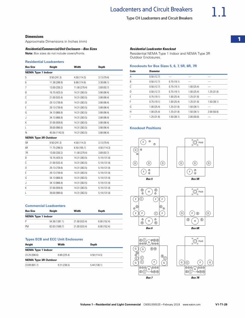
Volume 1—Residential and Light Commercial CA08100002E—February 2018 www.eaton.com V1-T1-29
1
1
1
1
1
1
1
1
1
1
1
1
1
1
1
1
1
1
1
1
1
1
1
1
1
1
1
1
1
1
1.1Loadcenters and Circuit Breakers
Type CH Loadcenters and Circuit Breakers
DimensionsApproximate Dimensions in Inches (mm)
Residential/Commercial/Unit Enclosure—Box SizesNote: Box sizes do not include covers/fronts.
Residential Loadcenters
Commercial Loadcenters
Types ECB and ECC Unit Enclosures
Residential Loadcenter KnockoutResidential NEMA Type 1 Indoor and NEMA Type 3R Outdoor Enclosures.
Knockouts for Box Sizes 5, 6, 7, 5R, 6R, 7R
Knockout Positions
Box Size Height Width Depth
NEMA Type 1 Indoor
5 9.50 (241.3) 4.50 (114.3) 3.13 (79.4)
6 11.38 (288.9) 6.88 (174.6) 3.39 (86.1)
7 13.00 (330.2) 11.00 (279.4) 3.69 (93.7)
B 16.75 (425.5) 14.31 (363.5) 3.88 (98.4)
C 21.00 (533.4) 14.31 (363.5) 3.88 (98.4)
D 29.13 (739.8) 14.31 (363.5) 3.88 (98.4)
E 29.13 (739.8) 14.31 (363.5) 3.88 (98.4)
G 34.13 (866.8) 14.31 (363.5) 3.88 (98.4)
J 34.13 (866.8) 14.31 (363.5) 3.88 (98.4)
K 37.00 (939.8) 14.31 (363.5) 3.88 (98.4)
L 39.00 (990.6) 14.31 (363.5) 3.88 (98.4)
N 45.00 (1143.0) 14.31 (363.5) 3.88 (98.4)
NEMA Type 3R Outdoor
5R 9.50 (241.3) 4.50 (114.3) 3.13 (79.4)
6R 11.75 (298.5) 6.50 (165.1) 4.50 (114.3)
7R 13.00 (330.2) 11.00 (279.4) 3.69 (93.7)
B 16.75 (425.5) 14.31 (363.5) 5.19 (131.8)
C 21.00 (533.4) 14.31 (363.5) 5.19 (131.8)
D 29.13 (739.8) 14.31 (363.5) 5.19 (131.8)
E 29.13 (739.8) 14.31 (363.5) 5.19 (131.8)
G 34.13 (866.8) 14.31 (363.5) 5.19 (131.8)
J 34.13 (866.8) 14.31 (363.5) 5.19 (131.8)
K 37.00 (939.8) 14.31 (363.5) 5.19 (131.8)
L 39.00 (990.6) 14.31 (363.5) 5.19 (131.8)
Box Size Height Width Depth
NEMA Type 1 Indoor
P 54.38 (1381.1) 21.00 (533.4) 6.00 (152.4)
PM 62.63 (1590.7) 21.00 (533.4) 6.00 (152.4)
Height Width Depth
NEMA Type 1 Indoor
23.25 (590.6) 8.88 (225.4) 4.50 (114.3)
NEMA Type 3R Outdoor
23.69 (601.7) 9.31 (236.5) 5.44 (138.1)
Code Diameter
A 0.50 (12.7) — — —
B 0.50 (12.7) 0.75 (19.1) — —
C 0.50 (12.7) 0.75 (19.1) 1.00 (25.4) —
D 0.50 (12.7) 0.75 (19.1) 1.00 (25.4) 1.25 (31.8)
E 0.75 (19.1) 1.00 (25.4) 1.25 (31.8) —
F 0.75 (19.1) 1.00 (25.4) 1.25 (31.8) 1.50 (38.1)
G 1.00 (25.4) 1.25 (31.8) 1.50 (38.1) —
H 1.00 (25.4) 1.25 (31.8) 1.50 (38.1) 2.00 (50.8)
I 1.25 (31.8) 1.50 (38.1) 2.00 (50.8) —
Box 6R
Box 7 Box 7R
Box 5 Box 5R
Box 6
A
A
D D D
F
Hub
A
A
B
A
B
B
C
C
F F
FF
AB
F
F
H
A
B
A
BH
F
B B
B
H
Hub
D D
A
A
AA
A
AAA
AAA AAA
B B B
A B B
B
B
B
B
C CC
C
C
B C
G
G
GG
G GF
AAA AAA
A B BB C
C
G
G GF
Hub
A
A
A
A
A
A
D D D
D
F
F
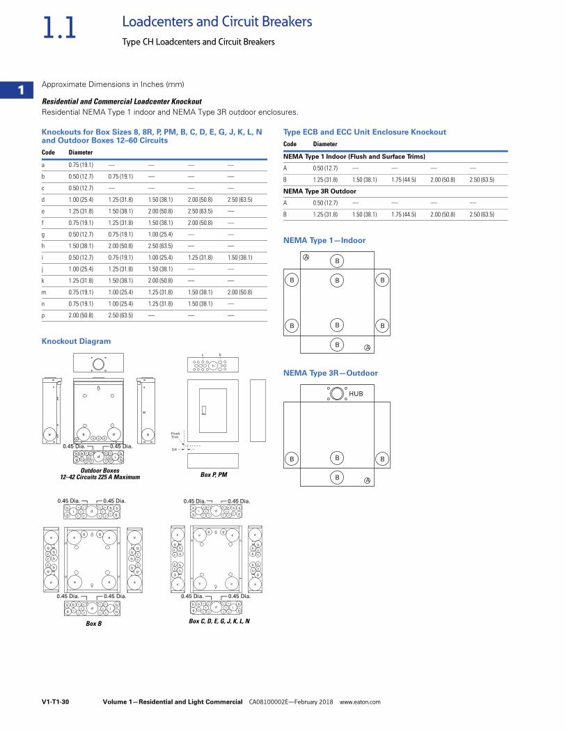
V1-T1-30 Volume 1—Residential and Light Commercial CA08100002E—February 2018 www.eaton.com
1
1
1
1
1
1
1
1
1
1
1
1
1
1
1
1
1
1
1
1
1
1
1
1
1
1
1
1
1
1
1.1 Loadcenters and Circuit Breakers
Type CH Loadcenters and Circuit Breakers
Approximate Dimensions in Inches (mm)
Residential and Commercial Loadcenter Knockout Residential NEMA Type 1 indoor and NEMA Type 3R outdoor enclosures.
Knockouts for Box Sizes 8, 8R, P, PM, B, C, D, E, G, J, K, L, N and Outdoor Boxes 12–60 Circuits
Knockout Diagram
Type ECB and ECC Unit Enclosure Knockout
NEMA Type 1—Indoor
NEMA Type 3R—Outdoor
Code Diameter
a 0.75 (19.1) — — — —
b 0.50 (12.7) 0.75 (19.1) — — —
c 0.50 (12.7) — — — —
d 1.00 (25.4) 1.25 (31.8) 1.50 (38.1) 2.00 (50.8) 2.50 (63.5)
e 1.25 (31.8) 1.50 (38.1) 2.00 (50.8) 2.50 (63.5) —
f 0.75 (19.1) 1.25 (31.8) 1.50 (38.1) 2.00 (50.8) —
g 0.50 (12.7) 0.75 (19.1) 1.00 (25.4) — —
h 1.50 (38.1) 2.00 (50.8) 2.50 (63.5) — —
i 0.50 (12.7) 0.75 (19.1) 1.00 (25.4) 1.25 (31.8) 1.50 (38.1)
j 1.00 (25.4) 1.25 (31.8) 1.50 (38.1) — —
k 1.25 (31.8) 1.50 (38.1) 2.00 (50.8) — —
m 0.75 (19.1) 1.00 (25.4) 1.25 (31.8) 1.50 (38.1) 2.00 (50.8)
n 0.75 (19.1) 1.00 (25.4) 1.25 (31.8) 1.50 (38.1) —
p 2.00 (50.8) 2.50 (63.5) — — —
e e e e
dcc
cc c
b
bi
cc
cc c
b
g
bc
c c ca
FlushTrim
3/4
c
h
b
b
e
g
b
b
c
c
c
g
e
b
e
g
b
b
c
c
c
g
e
e e
ee
g g
d
c c
c
cc
b
bi
c c
c
cc
b
g
b
c
d
cc
c
c c
b
bi
cc
c
c c
b
g
b
c
0.45 Dia.0.45 Dia.
0.45 Dia.0.45 Dia.
b
e
g
b
b
c
c
g
e
e e
ee
g g
b
c
c
b
e
g
b
b
c
c
c
g
e
bc
d
c c
c
cc
b
bi
c c
c
cc
b
g
b
c
d
cc
c
c c
b
bi
cc
c
c c
b
g
b
c
0.45 Dia.0.45 Dia.
Box P, PMOutdoor Boxes
12–42 Circuits 225 A Maximum
Box B Box C, D, E, G, J, K, L, N
0.45 Dia.0.45 Dia.
0.45 Dia.0.45 Dia.
Code Diameter
NEMA Type 1 Indoor (Flush and Surface Trims)
A 0.50 (12.7) — — — —
B 1.25 (31.8) 1.50 (38.1) 1.75 (44.5) 2.00 (50.8) 2.50 (63.5)
NEMA Type 3R Outdoor
A 0.50 (12.7) — — — —
B 1.25 (31.8) 1.50 (38.1) 1.75 (44.5) 2.00 (50.8) 2.50 (63.5)
B
B
B
B
A
A
B
B
B
B
B
B A
B B
HUB
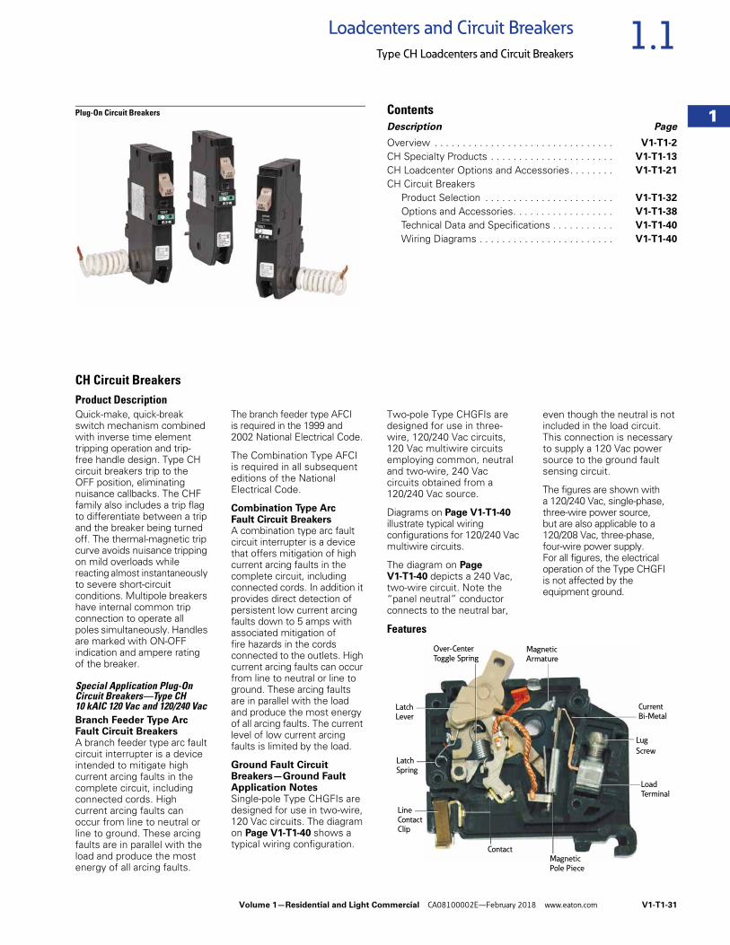
Volume 1—Residential and Light Commercial CA08100002E—February 2018 www.eaton.com V1-T1-31
1
1
1
1
1
1
1
1
1
1
1
1
1
1
1
1
1
1
1
1
1
1
1
1
1
1
1
1
1
1
1.1Loadcenters and Circuit Breakers
Type CH Loadcenters and Circuit Breakers
Plug-On Circuit Breakers ContentsDescription Page
Overview . . . . . . . . . . . . . . . . . . . . . . . . . . . . . . . . V1-T1-2
CH Specialty Products . . . . . . . . . . . . . . . . . . . . . . V1-T1-13
CH Loadcenter Options and Accessories. . . . . . . . V1-T1-21
CH Circuit BreakersProduct Selection . . . . . . . . . . . . . . . . . . . . . . . V1-T1-32
Options and Accessories. . . . . . . . . . . . . . . . . . V1-T1-38
Technical Data and Specifications . . . . . . . . . . . V1-T1-40
Wiring Diagrams . . . . . . . . . . . . . . . . . . . . . . . . V1-T1-40
CH Circuit BreakersProduct DescriptionQuick-make, quick-break switch mechanism combined with inverse time element tripping operation and trip- free handle design. Type CH circuit breakers trip to the OFF position, eliminating nuisance callbacks. The CHF family also includes a trip flag to differentiate between a trip and the breaker being turned off. The thermal-magnetic trip curve avoids nuisance tripping on mild overloads while reacting almost instantaneously to severe short-circuit conditions. Multipole breakers have internal common trip connection to operate all poles simultaneously. Handles are marked with ON-OFF indication and ampere rating of the breaker.
Special Application Plug-On Circuit Breakers—Type CH 10 kAIC 120 Vac and 120/240 VacBranch Feeder Type Arc Fault Circuit BreakersA branch feeder type arc fault circuit interrupter is a device intended to mitigate high current arcing faults in the complete circuit, including connected cords. High current arcing faults can occur from line to neutral or line to ground. These arcing faults are in parallel with the load and produce the most energy of all arcing faults.
The branch feeder type AFCI is required in the 1999 and 2002 National Electrical Code.
The Combination Type AFCI is required in all subsequent editions of the National Electrical Code.
Combination Type Arc Fault Circuit BreakersA combination type arc fault circuit interrupter is a device that offers mitigation of high current arcing faults in the complete circuit, including connected cords. In addition it provides direct detection of persistent low current arcing faults down to 5 amps with associated mitigation of fire hazards in the cords connected to the outlets. High current arcing faults can occur from line to neutral or line to ground. These arcing faults are in parallel with the load and produce the most energy of all arcing faults. The current level of low current arcing faults is limited by the load.
Ground Fault Circuit Breakers—Ground Fault Application NotesSingle-pole Type CHGFIs are designed for use in two-wire, 120 Vac circuits. The diagram on Page V1-T1-40 shows a typical wiring configuration.
Two-pole Type CHGFIs are designed for use in three-wire, 120/240 Vac circuits, 120 Vac multiwire circuits employing common, neutral and two-wire, 240 Vac circuits obtained from a 120/240 Vac source.
Diagrams on Page V1-T1-40 illustrate typical wiring configurations for 120/240 Vac multiwire circuits.
The diagram on Page V1-T1-40 depicts a 240 Vac, two-wire circuit. Note the “panel neutral” conductor connects to the neutral bar,
even though the neutral is not included in the load circuit. This connection is necessary to supply a 120 Vac power source to the ground fault sensing circuit.
The figures are shown with a 120/240 Vac, single-phase, three-wire power source, but are also applicable to a 120/208 Vac, three-phase,four-wire power supply. For all figures, the electrical operation of the Type CHGFI is not affected by the equipment ground.
Features
Latch
Spring
Over-Center
Toggle Spring
Latch Lever
MagneticArmature
Current
Bi-Metal
Lug
Screw
Load
Terminal
Magnetic Pole Piece
Contact
Line
Contact Clip
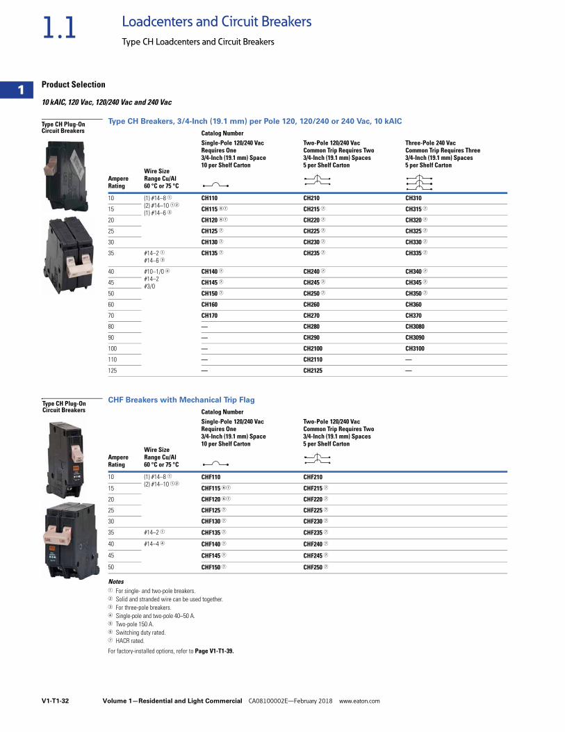
V1-T1-32 Volume 1—Residential and Light Commercial CA08100002E—February 2018 www.eaton.com
1
1
1
1
1
1
1
1
1
1
1
1
1
1
1
1
1
1
1
1
1
1
1
1
1
1
1
1
1
1
1.1 Loadcenters and Circuit Breakers
Type CH Loadcenters and Circuit Breakers
Product Selection
10 kAIC, 120 Vac, 120/240 Vac and 240 Vac
Type CH Breakers, 3/4-Inch (19.1 mm) per Pole 120, 120/240 or 240 Vac, 10 kAIC
CHF Breakers with Mechanical Trip Flag
Notes1 For single- and two-pole breakers.2 Solid and stranded wire can be used together.3 For three-pole breakers.4 Single-pole and two-pole 40–50 A. 5 Two-pole 150 A.6 Switching duty rated.7 HACR rated.
For factory-installed options, refer to Page V1-T1-39.
AmpereRating
Wire Size Range Cu/Al 60 °C or 75 °C
Catalog NumberSingle-Pole 120/240 Vac Requires One3/4-Inch (19.1 mm) Space10 per Shelf Carton
Two-Pole 120/240 Vac Common Trip Requires Two 3/4-Inch (19.1 mm) Spaces5 per Shelf Carton
Three-Pole 240 Vac Common Trip Requires Three 3/4-Inch (19.1 mm) Spaces5 per Shelf Carton
10 (1) #14–8 1(2) #14–10 12
(1) #14–6 3
CH110 CH210 CH310
15 CH115 67 CH215 7 CH315 7
20 CH120 67 CH220 7 CH320 7
25 CH125 7 CH225 7 CH325 7
30 CH130 7 CH230 7 CH330 7
35 #14–2 1#14–6 3
CH135 7 CH235 7 CH335 7
40 #10–1/0 4#14–2 #3/0
CH140 7 CH240 7 CH340 7
45 CH145 7 CH245 7 CH345 7
50 CH150 7 CH250 7 CH350 7
60 CH160 CH260 CH360
70 CH170 CH270 CH370
80 — CH280 CH3080
90 — CH290 CH3090
100 — CH2100 CH3100
110 — CH2110 —
125 — CH2125 —
AmpereRating
Wire Size Range Cu/Al 60 °C or 75 °C
Catalog NumberSingle-Pole 120/240 Vac Requires One3/4-Inch (19.1 mm) Space10 per Shelf Carton
Two-Pole 120/240 Vac Common Trip Requires Two 3/4-Inch (19.1 mm) Spaces5 per Shelf Carton
10 (1) #14–8 1(2) #14–10 12
CHF110 CHF210
15 CHF115 67 CHF215 7
20 CHF120 67 CHF220 7
25 CHF125 7 CHF225 7
30 CHF130 7 CHF230 7
35 #14–2 1 CHF135 7 CHF235 7
40 #14–4 4 CHF140 7 CHF240 7
45 CHF145 7 CHF245 7
50 CHF150 7 CHF250 7
Type CH Plug-On Circuit Breakers
Type CH Plug-On Circuit Breakers
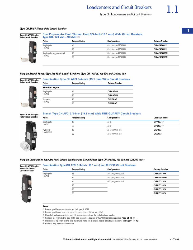
Volume 1—Residential and Light Commercial CA08100002E—February 2018 www.eaton.com V1-T1-33
1
1
1
1
1
1
1
1
1
1
1
1
1
1
1
1
1
1
1
1
1
1
1
1
1
1
1
1
1
1
1.1Loadcenters and Circuit Breakers
Type CH Loadcenters and Circuit Breakers
Type CH AF/GF Single-Pole Circuit Breaker
Dual Purpose Arc Fault/Ground Fault 3/4-Inch (19.1 mm) Wide Circuit Breakers, Type CH, 120 Vac—10 kAIC 12
Plug-On Branch Feeder Type Arc Fault Circuit Breakers, Type CH 10 kAIC, 120 Vac and 120/240 Vac
Combination Type CH AFCI 3/4-Inch (19.1 mm) Wide Circuit Breakers
Branch Type CH AFCI 3/4-Inch (19.1 mm) Wide FIRE-GUARD® Circuit Breakers
Plug-On Combination Type Arc Fault Circuit Breakers and Ground Fault, Type CH 10 kAIC, 120 Vac and 120/240 Vac 6
Combination Type CH AFCI 3/4-Inch (19.1 mm) and CHGFCI Circuit Breakers
Notes1 Breaker qualifies as combination arc fault, per UL 1699. 2 Breaker qualifies as personnel protection ground fault, (5 mA) per UL 943. 3 Clamshell packaging available with CS modification code on the end of catalog number.4 Common trip refers to two-pole 240 V load application sourced by 120/240 Vac (see diagram on Page V1-T1-40).5 Independent trip refers to two-pole multi-wire, home run or shared neutral circuits (see diagrams on Page V1-T1-40).6 Requires plug-on neutral loadcenter.
Poles Ampere Rating Configuration Catalog Number
Single-pole 10 kAIC
15 Combination AFCI GFCI CHFAFGF115 3
20 Combination AFCI GFCI CHFAFGF120 3
Single-pole, plug-on neutral 10 kAIC
15 Combination AFCI GFCI CHFAFGF115PN
20 Combination AFCI GFCI CHFAFGF120PN
Poles Ampere Rating Catalog Number
Standard Pigtail
Single-pole10 kAIC
15 CHFCAF115
20 CHFCAF120
Two-pole10 kAIC
15 CH215CAF
20 CH220CAF
Poles Ampere Rating Configuration Catalog Number
Single-pole10 kAIC
15 AFCI CH115AF 3
20 AFCI CH120AF 3
Two-pole10 kAIC 45
15 AFCI common trip CH215AF
20 AFCI common trip CH220AF
Poles Ampere Rating Configuration Catalog Number
Single-pole10 kAIC
15 AFCI plug-on neutral CHFCAF115PN
20 AFCI plug-on neutral CHFCAFT120PN
15 GFCI plug-on neutral CHFGFT115PN
20 CHFGFT120PN
25 CHFGFT125PN
30 CHFGFT130PN
Type CH AFCI Single-Pole Circuit Breaker
Type CH AFCI Single-Pole Circuit Breaker
Type CH AFCI Single-Pole Circuit Breaker
Type CH AFCI Single-Pole PON Combo Circuit Breaker
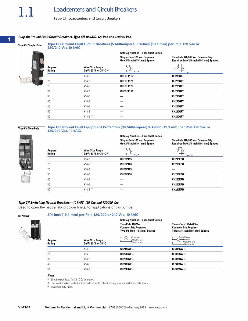
V1-T1-34 Volume 1—Residential and Light Commercial CA08100002E—February 2018 www.eaton.com
1
1
1
1
1
1
1
1
1
1
1
1
1
1
1
1
1
1
1
1
1
1
1
1
1
1
1
1
1
1
1.1 Loadcenters and Circuit Breakers
Type CH Loadcenters and Circuit Breakers
Plug-On Ground Fault Circuit Breakers, Type CH 10 kAIC, 120 Vac and 120/240 Vac
Type CH Ground Fault Circuit Breakers (5 Milliampere) 3/4-Inch (19.1 mm) per Pole 120 Vac or 120/240 Vac,10 kAIC
Type CH Ground Fault Equipment Protectors (30 Milliampere) 3/4-Inch (19.1 mm) per Pole 120 Vac or 120/240 Vac, 10 kAIC
Type CH Switching Neutral Breakers—10 kAIC, 120 Vac and 120/240 VacUsed to open the neutral along power line(s) for applications of gas pumps.
3/4-Inch (19.1 mm) per Pole 120/240 or 240 Vac, 10 kAIC
Notes1 60 A breaker listed for 75 °C Cu wire only.2 For circuit breakers with shunt trip, add ST suffix. Shunt trip requires one additional pole space. 3 Switching duty rated.
Ampere Rating
Wire Size Range Cu/Al 60 °C or 75 °C 1
Catalog Number—1 per Shelf CartonSingle-Pole 120 Vac Requires One 3/4-Inch (19.1 mm) Space
Two-Pole 120/240 Vac Common Trip Requires Two 3/4-Inch (19.1 mm) Spaces
15 #14–6 CHFGFT115 CH215GFT
20 #14–6 CHFGFT120 CH220GFT
25 #14–6 CHFGFT125 CH225GFT
30 #14–6 CHFGFT130 CH230GFT
35 #14–6 — CH235GFT
40 #14–6 — CH240GFT
45 #14–6 — CH245GFT
50 #14–6 — CH250GFT
60 #14–6 1 — CH260GFT
Ampere Rating
Wire Size Range Cu/Al 60 °C or 75 °C 1
Catalog Number—1 per Shelf CartonSingle-Pole 120 Vac Requires One 3/4-Inch (19.1 mm) Space
Two-Pole 120/240 Vac Common Trip Requires Two 3/4-Inch (19.1 mm) Spaces
15 #14–6 CHFEP115 CH215EPD
20 #14–6 CHFEP120 CH220EPD
25 #14–6 CHFEP125 —
30 #14–6 CHFEP130 CH230EPD
40 #14–6 — CH240EPD
50 #14–6 — CH250EPD
60 #14–6 1 — CH260EPD
AmpereRating
Wire Size Range Cu/Al 60 °C or 75 °C
Catalog Number—1 per Shelf CartonTwo-Pole 120 Vac Common Trip Requires Two 3/4-Inch (19.1 mm) Spaces
Three-Pole 120/240 VacCommon Trip Requires Three 3/4-Inch (19.1 mm) Spaces
15 #14–8 CH215SW 2 CH315SW 3
20 #14–8 CH220SW 2 CH320SW 3
30 #14–8 CH230SW 2 CH330SW 3
40 #14–8 CH240SW 2 CH340SW 3
50 #14–8 CH250SW 2 CH350SW 3
Type CH Single-Pole
Type CH Two-Pole
CH220SW
Neutral In
Neutral Out
(Hot leg)
Neutral In
Neutral OutPhase
Phase
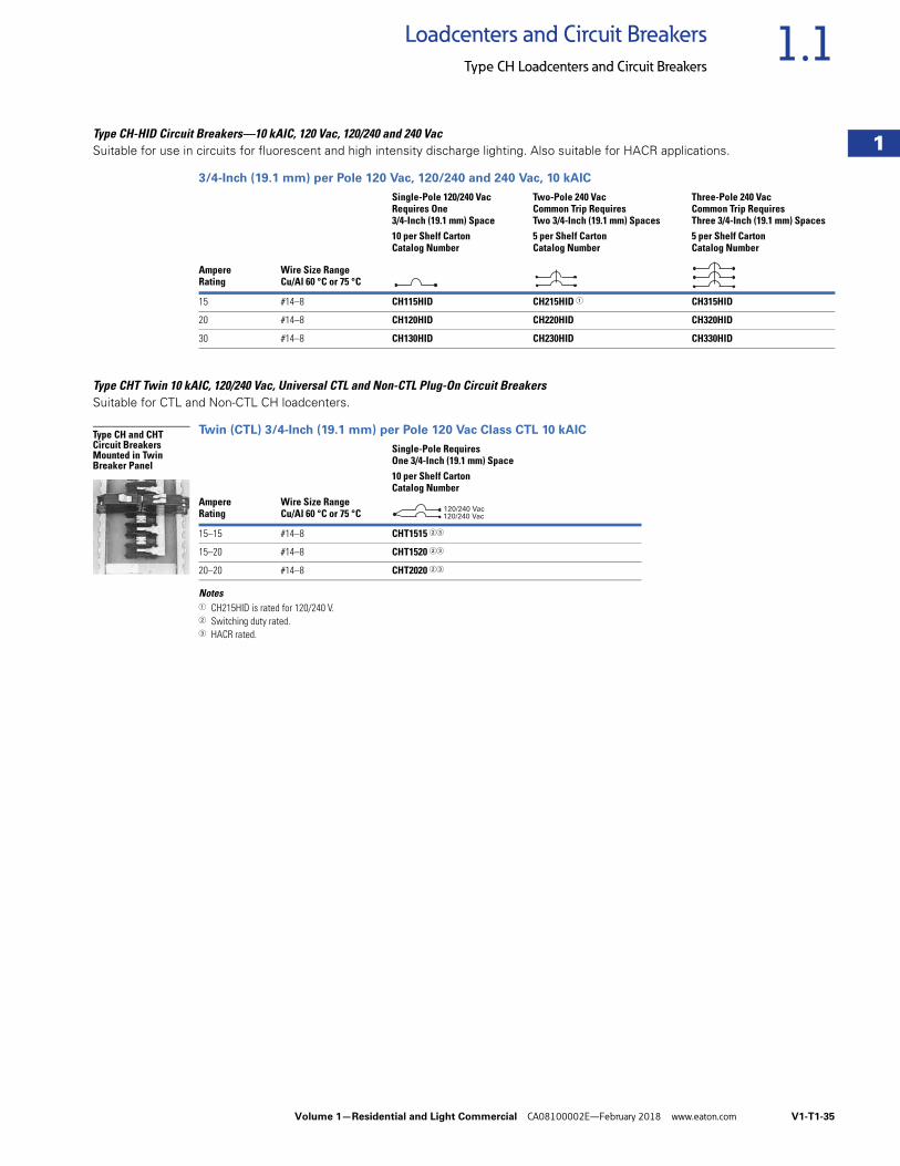
Volume 1—Residential and Light Commercial CA08100002E—February 2018 www.eaton.com V1-T1-35
1
1
1
1
1
1
1
1
1
1
1
1
1
1
1
1
1
1
1
1
1
1
1
1
1
1
1
1
1
1
1.1Loadcenters and Circuit Breakers
Type CH Loadcenters and Circuit Breakers
Type CH-HID Circuit Breakers—10 kAIC, 120 Vac, 120/240 and 240 VacSuitable for use in circuits for fluorescent and high intensity discharge lighting. Also suitable for HACR applications.
3/4-Inch (19.1 mm) per Pole 120 Vac, 120/240 and 240 Vac, 10 kAIC
Type CHT Twin 10 kAIC, 120/240 Vac, Universal CTL and Non-CTL Plug-On Circuit BreakersSuitable for CTL and Non-CTL CH loadcenters.
Twin (CTL) 3/4-Inch (19.1 mm) per Pole 120 Vac Class CTL 10 kAIC
Notes1 CH215HID is rated for 120/240 V.2 Switching duty rated.3 HACR rated.
AmpereRating
Wire Size RangeCu/Al 60 °C or 75 °C
Single-Pole 120/240 Vac Requires One 3/4-Inch (19.1 mm) Space
Two-Pole 240 VacCommon Trip Requires Two 3/4-Inch (19.1 mm) Spaces
Three-Pole 240 VacCommon Trip Requires Three 3/4-Inch (19.1 mm) Spaces
10 per Shelf CartonCatalog Number
5 per Shelf CartonCatalog Number
5 per Shelf CartonCatalog Number
15 #14–8 CH115HID CH215HID 1 CH315HID
20 #14–8 CH120HID CH220HID CH320HID
30 #14–8 CH130HID CH230HID CH330HID
AmpereRating
Wire Size Range Cu/Al 60 °C or 75 °C
Single-Pole Requires One 3/4-Inch (19.1 mm) Space10 per Shelf CartonCatalog Number
15–15 #14–8 CHT1515 23
15–20 #14–8 CHT1520 23
20–20 #14–8 CHT2020 23
Type CH and CHT Circuit Breakers Mounted in Twin Breaker Panel
120/240 Vac120/240 Vac
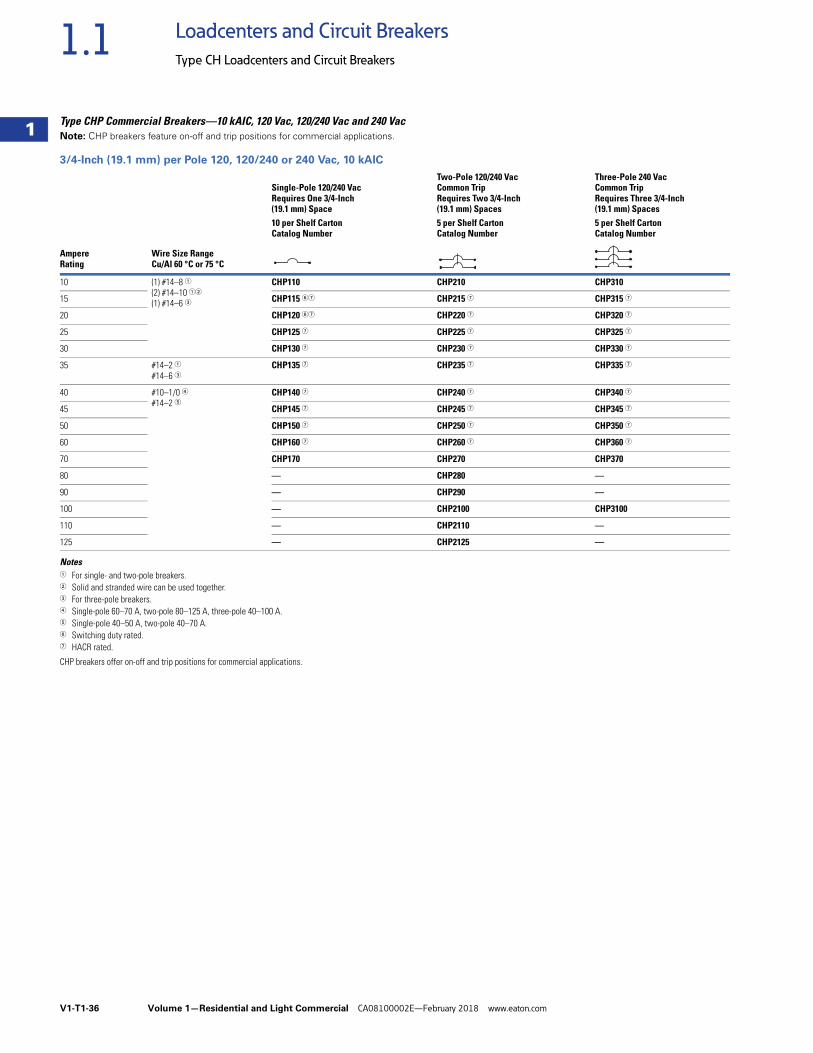
V1-T1-36 Volume 1—Residential and Light Commercial CA08100002E—February 2018 www.eaton.com
1
1
1
1
1
1
1
1
1
1
1
1
1
1
1
1
1
1
1
1
1
1
1
1
1
1
1
1
1
1
1.1 Loadcenters and Circuit Breakers
Type CH Loadcenters and Circuit Breakers
Type CHP Commercial Breakers—10 kAIC, 120 Vac, 120/240 Vac and 240 VacNote: CHP breakers feature on-off and trip positions for commercial applications.
3/4-Inch (19.1 mm) per Pole 120, 120/240 or 240 Vac, 10 kAIC
Notes1 For single- and two-pole breakers.2 Solid and stranded wire can be used together.3 For three-pole breakers.4 Single-pole 60–70 A, two-pole 80–125 A, three-pole 40–100 A.5 Single-pole 40–50 A, two-pole 40–70 A.6 Switching duty rated.7 HACR rated.
CHP breakers offer on-off and trip positions for commercial applications.
AmpereRating
Wire Size RangeCu/Al 60 °C or 75 °C
Single-Pole 120/240 VacRequires One 3/4-Inch (19.1 mm) Space
Two-Pole 120/240 VacCommon TripRequires Two 3/4-Inch (19.1 mm) Spaces
Three-Pole 240 VacCommon TripRequires Three 3/4-Inch (19.1 mm) Spaces
10 per Shelf CartonCatalog Number
5 per Shelf CartonCatalog Number
5 per Shelf CartonCatalog Number
10 (1) #14–8 1(2) #14–10 12
(1) #14–6 3
CHP110 CHP210 CHP310
15 CHP115 67 CHP215 7 CHP315 7
20 CHP120 67 CHP220 7 CHP320 7
25 CHP125 7 CHP225 7 CHP325 7
30 CHP130 7 CHP230 7 CHP330 7
35 #14–2 1#14–6 3
CHP135 7 CHP235 7 CHP335 7
40 #10–1/0 4#14–2 5
CHP140 7 CHP240 7 CHP340 7
45 CHP145 7 CHP245 7 CHP345 7
50 CHP150 7 CHP250 7 CHP350 7
60 CHP160 7 CHP260 7 CHP360 7
70 CHP170 CHP270 CHP370
80 — CHP280 —
90 — CHP290 —
100 — CHP2100 CHP3100
110 — CHP2110 —
125 — CHP2125 —
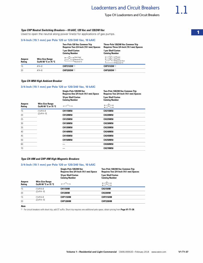
Volume 1—Residential and Light Commercial CA08100002E—February 2018 www.eaton.com V1-T1-37
1
1
1
1
1
1
1
1
1
1
1
1
1
1
1
1
1
1
1
1
1
1
1
1
1
1
1
1
1
1
1.1Loadcenters and Circuit Breakers
Type CH Loadcenters and Circuit Breakers
Type CHP Neutral Switching Breakers—10 kAIC, 120 Vac and 120/240 VacUsed to open the neutral along power line(s) for applications of gas pumps.
3/4-Inch (19.1 mm) per Pole 120 or 120/240 Vac, 10 kAIC
Type CH-M50 High Ambient Breaker
3/4-Inch (19.1 mm) per Pole 120 or 120/240 Vac, 10 kAIC
Type CH-HM and CHP-HM High Magnetic Breakers
3/4-Inch (19.1 mm) per Pole 120 or 120/240 Vac, 10 kAIC
Note1 For circuit breakers with shunt trip, add ST suffix. Shunt trip requires one additional pole space, obtain pricing from Page V1-T1-39.
AmpereRating
Wire Size RangeCu/Al 60 °C or 75 °C
Two-Pole 120 Vac Common TripRequires Two 3/4-Inch (19.1 mm) Spaces
Three-Pole 120/240 Vac Common TripRequires Three 3/4-Inch (19.1 mm) Spaces
1 per Shelf CartonCatalog Number
1 per Shelf CartonCatalog Number
15 #14–8 CHP215SW 1 CHP315SW 1
20 #14–8 CHP220SW 1 CHP320SW 1
AmpereRating
Wire Size RangeCu/Al 60 °C or 75 °C
Single-Pole 120/240 Vac Requires One 3/4-Inch (19.1 mm) Space
Two-Pole 120/240 Vac Common Trip Requires Two 3/4-Inch (19.1 mm) Spaces
10 per Shelf CartonCatalog Number
5 per Shelf CartonCatalog Number
15 (1) #14–8(2) #14–10
CH115M50 CH215M50
20 CH120M50 CH220M50
25 CH125M50 CH225M50
30 CH130M50 CH230M50
35 CH135M50 CH235M50
40 CH140M50 CH240M50
45 CH145M50 CH245M50
50 CH150M50 CH250M50
60 — CH260M50
70 — CH270M50
AmpereRating
Wire Size RangeCu/Al 60 °C or 75 °C
Single-Pole 120/240 Vac Requires One 3/4-Inch (19.1 mm) Space
Two-Pole 120/240 Vac Common Trip Requires Two 3/4-Inch (19.1 mm) Spaces
10 per Shelf CartonCatalog Number
5 per Shelf CartonCatalog Number
15 (1) #14–8(2) #14–10
CH115HM CH215HM
20 CH120HM CH220HM
15 (1) #14–8(2) #14–10
CHP115HM CHP215HM
20 CHP120HM CHP220HM
Neutral In
Neutral Out
(Hot leg)
Neutral In
Neutral OutPhase
Phase
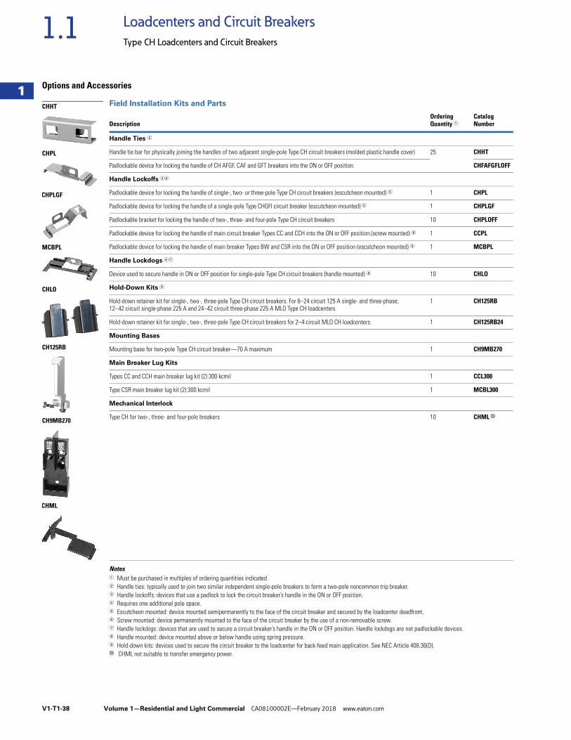
V1-T1-38 Volume 1—Residential and Light Commercial CA08100002E—February 2018 www.eaton.com
1
1
1
1
1
1
1
1
1
1
1
1
1
1
1
1
1
1
1
1
1
1
1
1
1
1
1
1
1
1
1.1 Loadcenters and Circuit Breakers
Type CH Loadcenters and Circuit Breakers
Options and Accessories
Field Installation Kits and Parts
Notes1 Must be purchased in multiples of ordering quantities indicated.2 Handle ties: typically used to join two similar independent single-pole breakers to form a two-pole noncommon trip breaker.3 Handle lockoffs: devices that use a padlock to lock the circuit breaker’s handle in the ON or OFF position.4 Requires one additional pole space.5 Escutcheon mounted: device mounted semipermanently to the face of the circuit breaker and secured by the loadcenter deadfront.6 Screw mounted: device permanently mounted to the face of the circuit breaker by the use of a non-removable screw.7 Handle lockdogs: devices that are used to secure a circuit breaker’s handle in the ON or OFF position. Handle lockdogs are not padlockable devices.8 Handle mounted: device mounted above or below handle using spring pressure.9 Hold-down kits: devices used to secure the circuit breaker to the loadcenter for back-feed main application. See NEC Article 408.36(D).j CHML not suitable to transfer emergency power.
DescriptionOrdering Quantity 1
Catalog Number
Handle Ties 2
Handle tie bar for physically joining the handles of two adjacent single-pole Type CH circuit breakers (molded plastic handle cover) 25 CHHT
Padlockable device for locking the handle of CH AFGF, CAF and GFT breakers into the ON or OFF position. CHFAFGFLOFF
Handle Lockoffs 34
Padlockable device for locking the handle of single-, two- or three-pole Type CH circuit breakers (escutcheon mounted) 5 1 CHPL
Padlockable device for locking the handle of a single-pole Type CHGFI circuit breaker (escutcheon mounted) 5 1 CHPLGF
Padlockable bracket for locking the handle of two-, three- and four-pole Type CH circuit breakers 10 CHPLOFF
Padlockable device for locking the handle of main circuit breaker Types CC and CCH into the ON or OFF position.(screw mounted) 6 1 CCPL
Padlockable device for locking the handle of main breaker Types BW and CSR into the ON or OFF position (escutcheon mounted) 5 1 MCBPL
Handle Lockdogs 47
Device used to secure handle in ON or OFF position for single-pole Type CH circuit breakers (handle mounted) 8 10 CHLO
Hold-Down Kits 9
Hold-down retainer kit for single-, two-, three-pole Type CH circuit breakers. For 6–24 circuit 125 A single- and three-phase, 12–42 circuit single-phase 225 A and 24–42 circuit three-phase 225 A MLO Type CH loadcenters
1 CH125RB
Hold-down retainer kit for single-, two-, three-pole Type CH circuit breakers for 2–4 circuit MLO CH loadcenters. 1 CH125RB24
Mounting Bases
Mounting base for two-pole Type CH circuit breaker—70 A maximum 1 CH9MB270
Main Breaker Lug Kits
Types CC and CCH main breaker lug kit (2) 300 kcmil 1 CCL300
Type CSR main breaker lug kit (2) 300 kcmil 1 MCBL300
Mechanical Interlock
Type CH for two-, three- and four-pole breakers 10 CHML j
CHHT
CHPL
CHPLGF
MCBPL
CHLO
CH125RB
CH9MB270
CHML
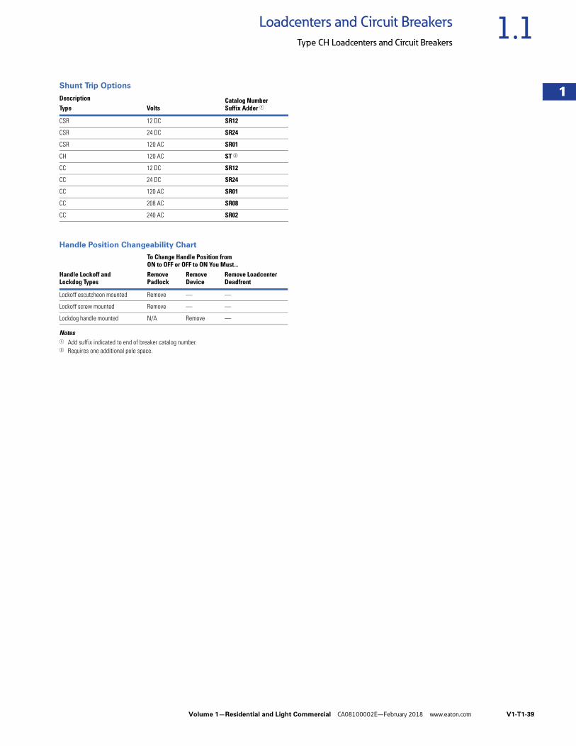
Volume 1—Residential and Light Commercial CA08100002E—February 2018 www.eaton.com V1-T1-39
1
1
1
1
1
1
1
1
1
1
1
1
1
1
1
1
1
1
1
1
1
1
1
1
1
1
1
1
1
1
1.1Loadcenters and Circuit Breakers
Type CH Loadcenters and Circuit Breakers
Shunt Trip Options
Handle Position Changeability Chart
Notes1 Add suffix indicated to end of breaker catalog number.2 Requires one additional pole space.
Description Catalog NumberSuffix Adder 1Type Volts
CSR 12 DC SR12
CSR 24 DC SR24
CSR 120 AC SR01
CH 120 AC ST 2
CC 12 DC SR12
CC 24 DC SR24
CC 120 AC SR01
CC 208 AC SR08
CC 240 AC SR02
Handle Lockoff andLockdog Types
To Change Handle Position from ON to OFF or OFF to ON You Must...RemovePadlock
RemoveDevice
Remove LoadcenterDeadfront
Lockoff escutcheon mounted Remove — —
Lockoff screw mounted Remove — —
Lockdog handle mounted N/A Remove —
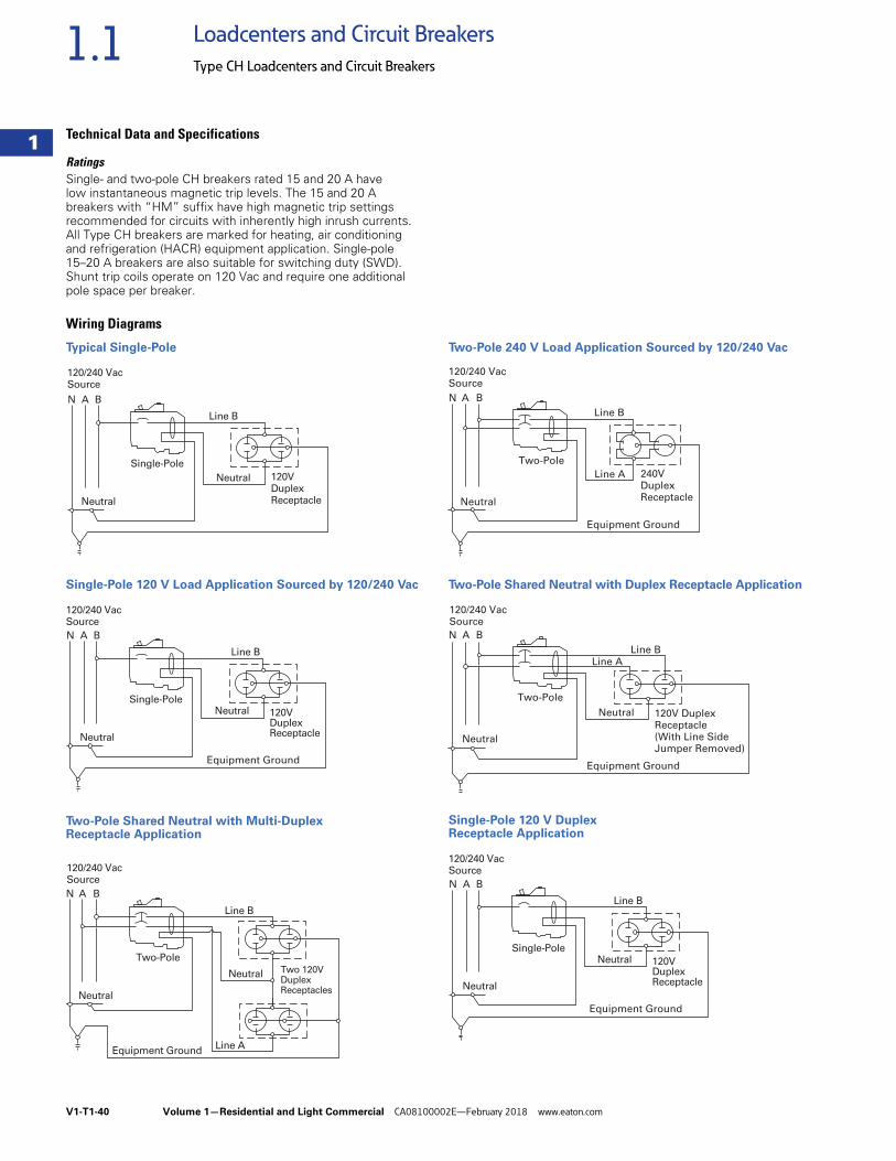
V1-T1-40 Volume 1—Residential and Light Commercial CA08100002E—February 2018 www.eaton.com
1
1
1
1
1
1
1
1
1
1
1
1
1
1
1
1
1
1
1
1
1
1
1
1
1
1
1
1
1
1
1.1 Loadcenters and Circuit Breakers
Type CH Loadcenters and Circuit Breakers
Technical Data and Specifications
RatingsSingle- and two-pole CH breakers rated 15 and 20 A have low instantaneous magnetic trip levels. The 15 and 20 A breakers with “HM” suffix have high magnetic trip settings recommended for circuits with inherently high inrush currents. All Type CH breakers are marked for heating, air conditioning and refrigeration (HACR) equipment application. Single-pole 15–20 A breakers are also suitable for switching duty (SWD). Shunt trip coils operate on 120 Vac and require one additional pole space per breaker.
Wiring Diagrams
Typical Single-Pole
Single-Pole 120 V Load Application Sourced by 120/240 Vac
Two-Pole Shared Neutral with Multi-Duplex Receptacle Application
Two-Pole 240 V Load Application Sourced by 120/240 Vac
Two-Pole Shared Neutral with Duplex Receptacle Application
Single-Pole 120 V Duplex Receptacle Application
N A B
120/240 VacSource
120VDuplexReceptacle
Single-Pole
Line B
Neutral
Neutral
N A B
120/240 VacSource
120VDuplexReceptacle
Single-Pole
Line B
Neutral
Neutral
Equipment Ground
N A B
120/240 VacSource
Two 120VDuplexReceptacles
Two-Pole
Line B
Line A
Neutral
Neutral
Equipment Ground
Line B
N A B
120/240 VacSource
Line A 240VDuplexReceptacle
Two-Pole
Neutral
Equipment Ground
N A B
120/240 VacSource
Line A
120V DuplexReceptacle(With Line SideJumper Removed)
Two-Pole
Line B
Neutral
Neutral
Equipment Ground
N A B
120/240 VacSource
120VDuplexReceptacle
Single-Pole
Line B
Neutral
Neutral
Equipment Ground
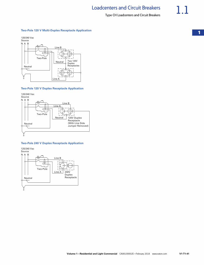
Volume 1—Residential and Light Commercial CA08100002E—February 2018 www.eaton.com V1-T1-41
1
1
1
1
1
1
1
1
1
1
1
1
1
1
1
1
1
1
1
1
1
1
1
1
1
1
1
1
1
1
1.1Loadcenters and Circuit Breakers
Type CH Loadcenters and Circuit Breakers
Two-Pole 120 V Multi-Duplex Receptacle Application
Two-Pole 120 V Duplex Receptacle Application
Two-Pole 240 V Duplex Receptacle Application
N A B
120/240 VacSource
Two 120VDuplexReceptacles
Two-Pole
Line B
Line A
Neutral
Neutral
N A B
120/240 VacSource
Line A
120V DuplexReceptacle(With Line SideJumper Removed)
Two-Pole
Line B
Neutral
Neutral
Line B
N A B
120/240 VacSource
Line A 240VDuplexReceptacle
Two-Pole
Neutral
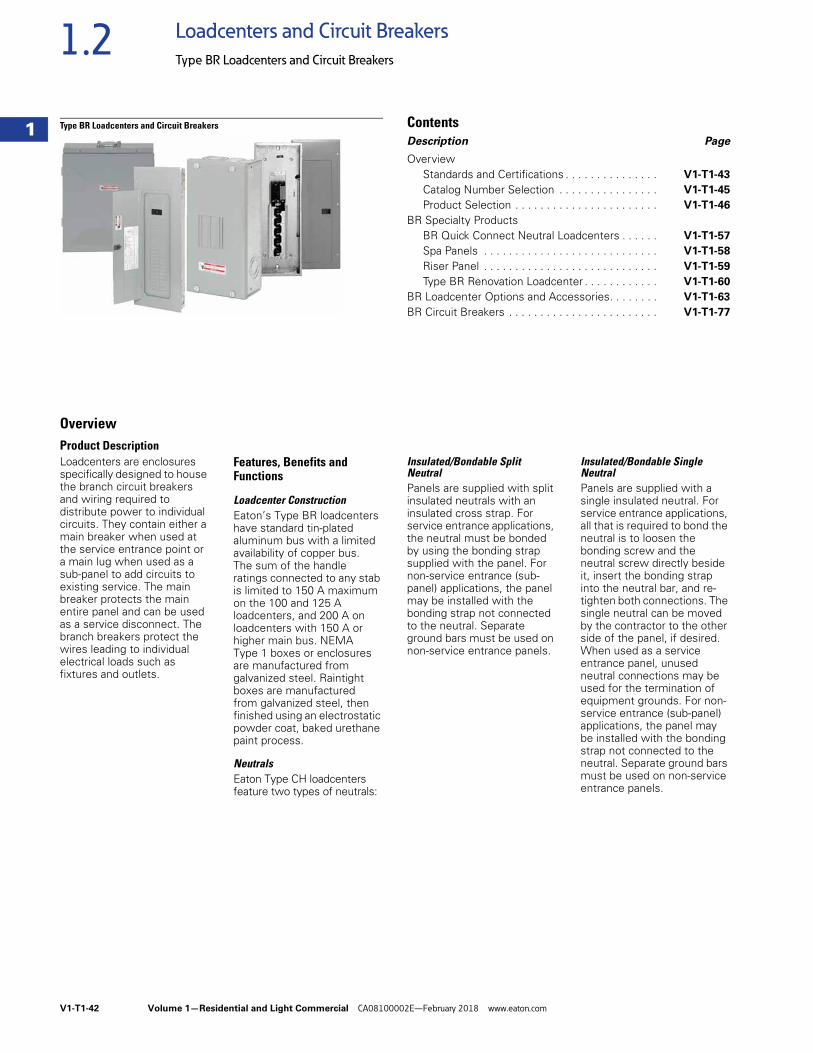
V1-T1-42 Volume 1—Residential and Light Commercial CA08100002E—February 2018 www.eaton.com
1
1
1
1
1
1
1
1
1
1
1
1
1
1
1
1
1
1
1
1
1
1
1
1
1
1
1
1
1
1
1.2 Loadcenters and Circuit Breakers
Type BR Loadcenters and Circuit Breakers
Type BR Loadcenters and Circuit Breakers ContentsDescription Page
OverviewStandards and Certifications . . . . . . . . . . . . . . . V1-T1-43
Catalog Number Selection . . . . . . . . . . . . . . . . V1-T1-45
Product Selection . . . . . . . . . . . . . . . . . . . . . . . V1-T1-46
BR Specialty ProductsBR Quick Connect Neutral Loadcenters . . . . . . V1-T1-57
Spa Panels . . . . . . . . . . . . . . . . . . . . . . . . . . . . V1-T1-58
Riser Panel . . . . . . . . . . . . . . . . . . . . . . . . . . . . V1-T1-59
Type BR Renovation Loadcenter . . . . . . . . . . . . V1-T1-60
BR Loadcenter Options and Accessories. . . . . . . . V1-T1-63
BR Circuit Breakers . . . . . . . . . . . . . . . . . . . . . . . . V1-T1-77
OverviewProduct Description Loadcenters are enclosures specifically designed to house the branch circuit breakers and wiring required to distribute power to individual circuits. They contain either a main breaker when used at the service entrance point or a main lug when used as a sub-panel to add circuits to existing service. The main breaker protects the main entire panel and can be used as a service disconnect. The branch breakers protect the wires leading to individual electrical loads such as fixtures and outlets.
Features, Benefits and Functions
Loadcenter ConstructionEaton’s Type BR loadcenters have standard tin-plated aluminum bus with a limited availability of copper bus. The sum of the handle ratings connected to any stab is limited to 150 A maximum on the 100 and 125 A loadcenters, and 200 A on loadcenters with 150 A or higher main bus. NEMA Type 1 boxes or enclosures are manufactured from galvanized steel. Raintight boxes are manufactured from galvanized steel, then finished using an electrostatic powder coat, baked urethane paint process.
NeutralsEaton Type CH loadcenters feature two types of neutrals:
Insulated/Bondable Split NeutralPanels are supplied with split insulated neutrals with an insulated cross strap. For service entrance applications, the neutral must be bonded by using the bonding strap supplied with the panel. For non-service entrance (sub-panel) applications, the panel may be installed with the bonding strap not connected to the neutral. Separate ground bars must be used on non-service entrance panels.
Insulated/Bondable Single NeutralPanels are supplied with a single insulated neutral. For service entrance applications, all that is required to bond the neutral is to loosen the bonding screw and the neutral screw directly beside it, insert the bonding strap into the neutral bar, and re-tighten both connections. The single neutral can be moved by the contractor to the other side of the panel, if desired. When used as a service entrance panel, unused neutral connections may be used for the termination of equipment grounds. For non-service entrance (sub-panel) applications, the panel may be installed with the bonding strap not connected to the neutral. Separate ground bars must be used on non-service entrance panels.
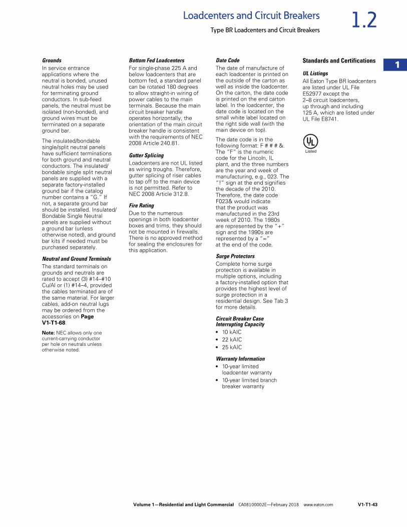
Volume 1—Residential and Light Commercial CA08100002E—February 2018 www.eaton.com V1-T1-43
1
1
1
1
1
1
1
1
1
1
1
1
1
1
1
1
1
1
1
1
1
1
1
1
1
1
1
1
1
1
1.2Loadcenters and Circuit Breakers
Type BR Loadcenters and Circuit Breakers
GroundsIn service entrance applications where the neutral is bonded, unused neutral holes may be used for terminating ground conductors. In sub-feed panels, the neutral must be isolated (non-bonded), and ground wires must be terminated on a separate ground bar.
The insulated/bondable single/split neutral panels have sufficient terminationsfor both ground and neutral conductors. The insulated/bondable single split neutral panels are supplied with a separate factory-installed ground bar if the catalog number contains a “G.” If not, a separate ground bar should be installed. Insulated/Bondable Single Neutral panels are supplied without a ground bar (unless otherwise noted), and ground bar kits if needed must be purchased separately.
Neutral and Ground TerminalsThe standard terminals on grounds and neutrals are rated to accept (3) #14–#10 Cu/Al or (1) #14–4, provided the cables terminated are of the same material. For larger cables, add-on neutral lugs may be ordered from the accessories on Page V1-T1-68.
Note: NEC allows only one current-carrying conductor per hole on neutrals unless otherwise noted.
Bottom Fed LoadcentersFor single-phase 225 A and below loadcenters that are bottom fed, a standard panel can be rotated 180 degrees to allow straight-in wiring of power cables to the main terminals. Because the main circuit breaker handle operates horizontally, the orientation of the main circuit breaker handle is consistent with the requirements of NEC 2008 Article 240.81.
Gutter SplicingLoadcenters are not UL listed as wiring troughs. Therefore, gutter splicing of riser cables to tap off to the main device is not permitted. Refer to NEC 2008 Article 312.8.
Fire RatingDue to the numerous openings in both loadcenter boxes and trims, they should not be mounted in firewalls. There is no approved method for sealing the enclosures for this application.
Date CodeThe date of manufacture of each loadcenter is printed on the outside of the carton as well as inside the loadcenter. On the carton, the date code is printed on the end carton label. In the loadcenter, the date code is located on the small white label located on the right side wall (with the main device on top).
The date code is in the following format: F # # # &. The “F” is the numeric code for the Lincoln, IL plant, and the three numbers are the year and week of manufacturing, e.g., 023. The “!” sign at the end signifies the decade of the 2010. Therefore, the date code F023& would indicate that the product was manufactured in the 23rd week of 2010. The 1980s are represented by the “+” sign and the 1990s are represented by a “=” at the end of the code.
Surge ProtectorsComplete home surge protection is available in multiple options, including a factory-installed option that provides the highest level of surge protection in a residential design. See Tab 3 for more details.
Circuit Breaker Case Interrupting Capacity● 10 kAIC● 22 kAIC● 25 kAIC
Warranty Information● 10-year limited
loadcenter warranty● 10-year limited branch
breaker warranty
Standards and Certifications
UL ListingsAll Eaton Type BR loadcenters are listed under UL File E52977 except the 2–8 circuit loadcenters, up through and including 125 A, which are listed under UL File E8741.
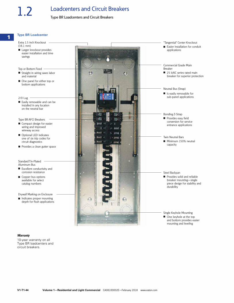
V1-T1-44 Volume 1—Residential and Light Commercial CA08100002E—February 2018 www.eaton.com
1
1
1
1
1
1
1
1
1
1
1
1
1
1
1
1
1
1
1
1
1
1
1
1
1
1
1
1
1
1
1.2 Loadcenters and Circuit Breakers
Type BR Loadcenters and Circuit Breakers
Type BR Loadcenter
Warranty10-year warranty on all Type BR loadcenters and circuit breakers.
Single Keyhole Mounting
One keyhole at the top and bottom provides easier mounting and leveling
Neutral Bus (Strap)
Is easily removable for sub-panel applications
Bonding Z-Strap
Provides easy field conversion for service entrance applications
Twin Neutral Bars
Minimum 150% neutral capacity
Steel Backpan
Provides solid and reliable breaker mounting—single piece design for stability and durability
Extra 1.5 inch Knockout (38.1 mm)
Larger knockout provides easier installation and time savings
“Tangential” Center Knockout
Easier installation for conduit applications
Commercial Grade Main Breaker
25 kAIC series rated main breaker for superior protection
2/0 Lug
Easily removable and can be installed in any location on the neutral bar
Drywall Marking on Enclosure
Indicates proper mounting depth for flush applications
Standard Tin-Plated Aluminum Bus
Excellent conductivity and corrosion resistance
Copper bus options available for select catalog numbers
Type BR AFCI Breakers
Compact design for easier wiring and improved wireway access
Optional LED indicates one of six trip codes for circuit diagnostics
Provides a clean gutter space
Top or Bottom Feed
Straight-in wiring saves labor and material
One panel for either top or bottom applications
■
■
■
■
■
■
■
■
■
■
■
■
■
■
■
■
■
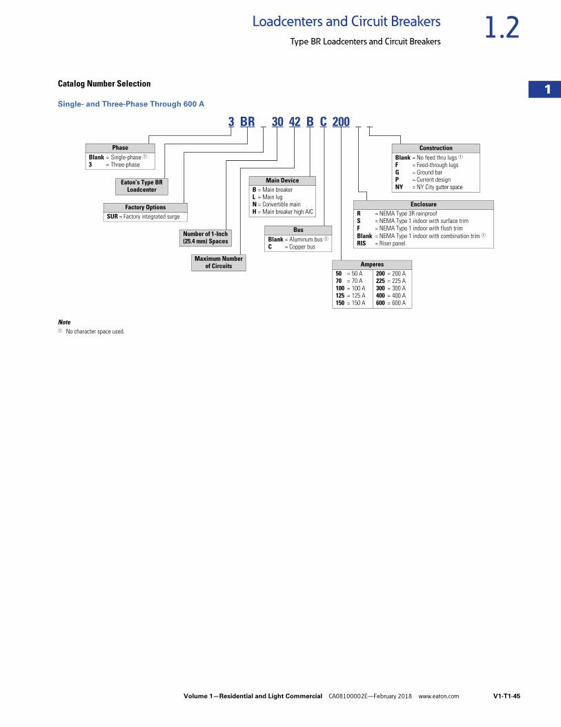
Volume 1—Residential and Light Commercial CA08100002E—February 2018 www.eaton.com V1-T1-45
1
1
1
1
1
1
1
1
1
1
1
1
1
1
1
1
1
1
1
1
1
1
1
1
1
1
1
1
1
1
1.2Loadcenters and Circuit Breakers
Type BR Loadcenters and Circuit Breakers
Catalog Number Selection
Single- and Three-Phase Through 600 A
Note1 No character space used.
3 BR 30 42 B C 200
PhaseBlank = Single-phase 13 = Three-phase
ConstructionBlank = No feed thru lugs 1F = Feed-through lugsG = Ground barP = Current designNY = NY City gutter space
Number of 1-Inch (25.4 mm) Spaces
Factory OptionsSUR = Factory integrated surge
Eaton’s Type BR Loadcenter
Maximum Numberof Circuits
BusBlank = Aluminum bus 1C = Copper bus
Main DeviceB = Main breakerL = Main lugN = Convertible mainH = Main breaker high AIC
EnclosureR = NEMA Type 3R rainproof S = NEMA Type 1 indoor with surface trimF = NEMA Type 1 indoor with flush trim Blank = NEMA Type 1 indoor with combination trim 1RIS = Riser panel
Amperes50 = 50 A70 = 70 A100 = 100 A125 = 125 A150 = 150 A
200 = 200 A225 = 225 A300 = 300 A400 = 400 A600 = 600 A
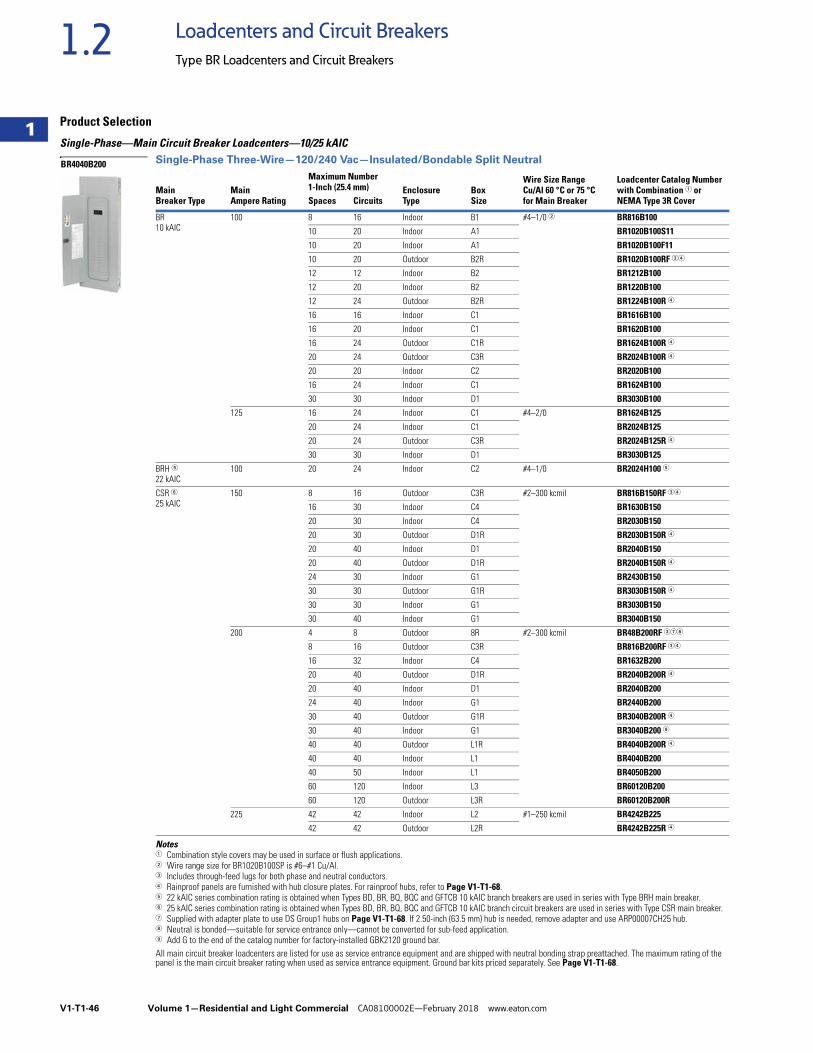
V1-T1-46 Volume 1—Residential and Light Commercial CA08100002E—February 2018 www.eaton.com
1
1
1
1
1
1
1
1
1
1
1
1
1
1
1
1
1
1
1
1
1
1
1
1
1
1
1
1
1
1
1.2 Loadcenters and Circuit Breakers
Type BR Loadcenters and Circuit Breakers
Product Selection
Single-Phase—Main Circuit Breaker Loadcenters—10/25 kAICSingle-Phase Three-Wire—120/240 Vac—Insulated/Bondable Split Neutral
Notes1 Combination style covers may be used in surface or flush applications.2 Wire range size for BR1020B100SP is #6–#1 Cu/Al.3 Includes through-feed lugs for both phase and neutral conductors.4 Rainproof panels are furnished with hub closure plates. For rainproof hubs, refer to Page V1-T1-68.5 22 kAIC series combination rating is obtained when Types BD, BR, BQ, BQC and GFTCB 10 kAIC branch breakers are used in series with Type BRH main breaker.6 25 kAIC series combination rating is obtained when Types BD, BR, BQ, BQC and GFTCB 10 kAIC branch circuit breakers are used in series with Type CSR main breaker.7 Supplied with adapter plate to use DS Group1 hubs on Page V1-T1-68. If 2.50-inch (63.5 mm) hub is needed, remove adapter and use ARP00007CH25 hub.8 Neutral is bonded—suitable for service entrance only—cannot be converted for sub-feed application.9 Add G to the end of the catalog number for factory-installed GBK2120 ground bar.All main circuit breaker loadcenters are listed for use as service entrance equipment and are shipped with neutral bonding strap preattached. The maximum rating of the panel is the main circuit breaker rating when used as service entrance equipment. Ground bar kits priced separately. See Page V1-T1-68.
MainBreaker Type
MainAmpere Rating
Maximum Number1-Inch (25.4 mm) Enclosure
TypeBoxSize
Wire Size RangeCu/Al 60 °C or 75 °Cfor Main Breaker
Loadcenter Catalog Number with Combination 1 or NEMA Type 3R CoverSpaces Circuits
BR10 kAIC
100 8 16 Indoor B1 #4–1/0 2 BR816B100
10 20 Indoor A1 BR1020B100S11
10 20 Indoor A1 BR1020B100F11
10 20 Outdoor B2R BR1020B100RF 34
12 12 Indoor B2 BR1212B100
12 20 Indoor B2 BR1220B100
12 24 Outdoor B2R BR1224B100R 4
16 16 Indoor C1 BR1616B100
16 20 Indoor C1 BR1620B100
16 24 Outdoor C1R BR1624B100R 4
20 24 Outdoor C3R BR2024B100R 4
20 20 Indoor C2 BR2020B100
16 24 Indoor C1 BR1624B100
30 30 Indoor D1 BR3030B100
125 16 24 Indoor C1 #4–2/0 BR1624B125
20 24 Indoor C1 BR2024B125
20 24 Outdoor C3R BR2024B125R 4
30 30 Indoor D1 BR3030B125
BRH 522 kAIC
100 20 24 Indoor C2 #4–1/0 BR2024H100 5
CSR 625 kAIC
150 8 16 Outdoor C3R #2–300 kcmil BR816B150RF 34
16 30 Indoor C4 BR1630B150
20 30 Indoor C4 BR2030B150
20 30 Outdoor D1R BR2030B150R 4
20 40 Indoor D1 BR2040B150
20 40 Outdoor D1R BR2040B150R 4
24 30 Indoor G1 BR2430B150
30 30 Outdoor G1R BR3030B150R 4
30 30 Indoor G1 BR3030B150
30 40 Indoor G1 BR3040B150
200 4 8 Outdoor 8R #2–300 kcmil BR48B200RF 378
8 16 Outdoor C3R BR816B200RF 34
16 32 Indoor C4 BR1632B200
20 40 Outdoor D1R BR2040B200R 4
20 40 Indoor D1 BR2040B200
24 40 Indoor G1 BR2440B200
30 40 Outdoor G1R BR3040B200R 4
30 40 Indoor G1 BR3040B200 9
40 40 Outdoor L1R BR4040B200R 4
40 40 Indoor L1 BR4040B200
40 50 Indoor L1 BR4050B200
60 120 Indoor L3 BR60120B200
60 120 Outdoor L3R BR60120B200R
225 42 42 Indoor L2 #1–250 kcmil BR4242B225
42 42 Outdoor L2R BR4242B225R 4
BR4040B200
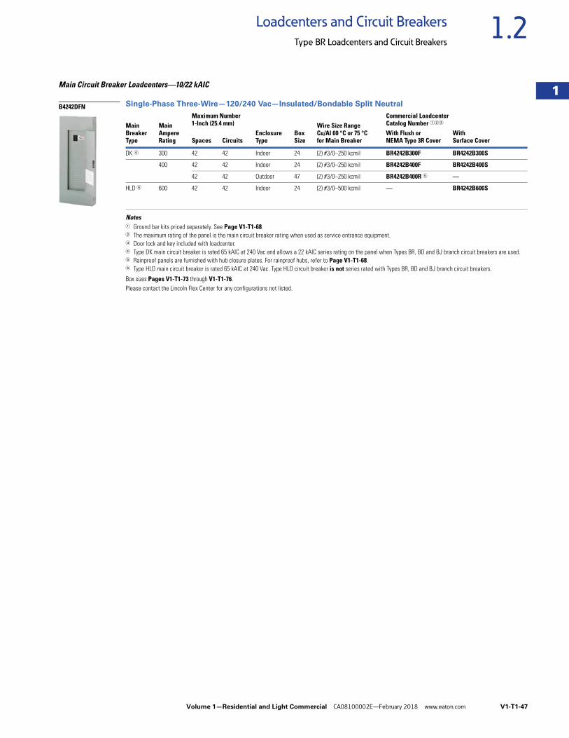
Volume 1—Residential and Light Commercial CA08100002E—February 2018 www.eaton.com V1-T1-47
1
1
1
1
1
1
1
1
1
1
1
1
1
1
1
1
1
1
1
1
1
1
1
1
1
1
1
1
1
1
1.2Loadcenters and Circuit Breakers
Type BR Loadcenters and Circuit Breakers
Main Circuit Breaker Loadcenters—10/22 kAIC
Single-Phase Three-Wire—120/240 Vac—Insulated/Bondable Split Neutral
Notes1 Ground bar kits priced separately. See Page V1-T1-68.2 The maximum rating of the panel is the main circuit breaker rating when used as service entrance equipment.3 Door lock and key included with loadcenter.4 Type DK main circuit breaker is rated 65 kAIC at 240 Vac and allows a 22 kAIC series rating on the panel when Types BR, BD and BJ branch circuit breakers are used. 5 Rainproof panels are furnished with hub closure plates. For rainproof hubs, refer to Page V1-T1-68.6 Type HLD main circuit breaker is rated 65 kAIC at 240 Vac. Type HLD circuit breaker is not series rated with Types BR, BD and BJ branch circuit breakers.
Box sizes Pages V1-T1-73 through V1-T1-76.Please contact the Lincoln Flex Center for any configurations not listed.
MainBreaker Type
MainAmpere Rating
Maximum Number1-Inch (25.4 mm)
EnclosureType
BoxSize
Wire Size RangeCu/Al 60 °C or 75 °Cfor Main Breaker
Commercial Loadcenter Catalog Number 123
Spaces CircuitsWith Flush orNEMA Type 3R Cover
WithSurface Cover
DK 4 300 42 42 Indoor 24 (2) #3/0–250 kcmil BR4242B300F BR4242B300S
400 42 42 Indoor 24 (2) #3/0–250 kcmil BR4242B400F BR4242B400S
42 42 Outdoor 47 (2) #3/0–250 kcmil BR4242B400R 5 —
HLD 6 600 42 42 Indoor 24 (2) #3/0–500 kcmil — BR4242B600S
B4242DFN
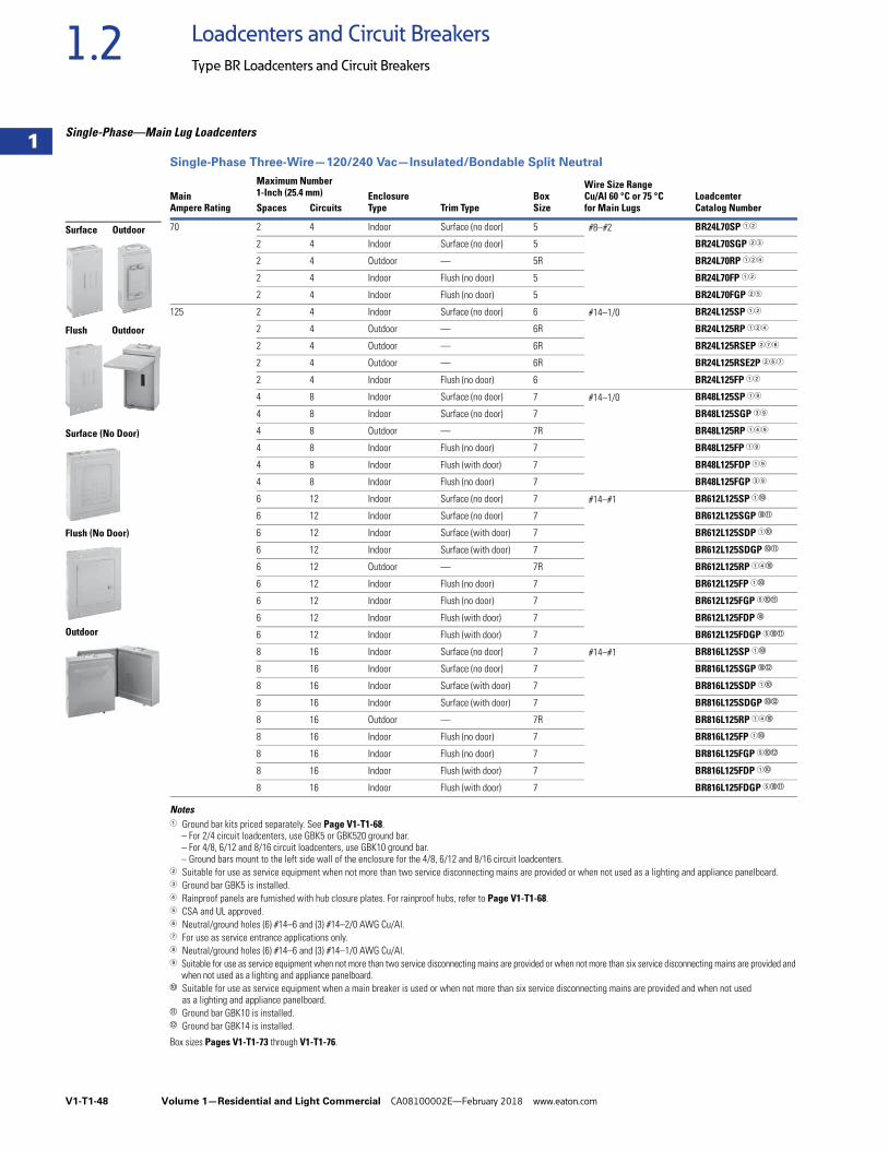
V1-T1-48 Volume 1—Residential and Light Commercial CA08100002E—February 2018 www.eaton.com
1
1
1
1
1
1
1
1
1
1
1
1
1
1
1
1
1
1
1
1
1
1
1
1
1
1
1
1
1
1
1.2 Loadcenters and Circuit Breakers
Type BR Loadcenters and Circuit Breakers
Single-Phase—Main Lug Loadcenters
Single-Phase Three-Wire—120/240 Vac—Insulated/Bondable Split Neutral
Notes1 Ground bar kits priced separately. See Page V1-T1-68.
– For 2/4 circuit loadcenters, use GBK5 or GBK520 ground bar.– For 4/8, 6/12 and 8/16 circuit loadcenters, use GBK10 ground bar.– Ground bars mount to the left side wall of the enclosure for the 4/8, 6/12 and 8/16 circuit loadcenters.
2 Suitable for use as service equipment when not more than two service disconnecting mains are provided or when not used as a lighting and appliance panelboard.3 Ground bar GBK5 is installed.4 Rainproof panels are furnished with hub closure plates. For rainproof hubs, refer to Page V1-T1-68.5 CSA and UL approved.6 Neutral/ground holes (6) #14–6 and (3) #14–2/0 AWG Cu/Al.7 For use as service entrance applications only.8 Neutral/ground holes (6) #14–6 and (3) #14–1/0 AWG Cu/Al.9 Suitable for use as service equipment when not more than two service disconnecting mains are provided or when not more than six service disconnecting mains are provided and
when not used as a lighting and appliance panelboard.j Suitable for use as service equipment when a main breaker is used or when not more than six service disconnecting mains are provided and when not used
as a lighting and appliance panelboard.k Ground bar GBK10 is installed.l Ground bar GBK14 is installed.
Box sizes Pages V1-T1-73 through V1-T1-76.
Main Ampere Rating
Maximum Number1-Inch (25.4 mm) Enclosure
Type Trim TypeBoxSize
Wire Size RangeCu/Al 60 °C or 75 °C for Main Lugs
LoadcenterCatalog NumberSpaces Circuits
70 2 4 Indoor Surface (no door) 5 #8–#2 BR24L70SP 12
2 4 Indoor Surface (no door) 5 BR24L70SGP 23
2 4 Outdoor — 5R BR24L70RP 124
2 4 Indoor Flush (no door) 5 BR24L70FP 12
2 4 Indoor Flush (no door) 5 BR24L70FGP 25
125 2 4 Indoor Surface (no door) 6 #14–1/0 BR24L125SP 12
2 4 Outdoor — 6R BR24L125RP 124
2 4 Outdoor — 6R BR24L125RSEP 278
2 4 Outdoor — 6R BR24L125RSE2P 267
2 4 Indoor Flush (no door) 6 BR24L125FP 12
4 8 Indoor Surface (no door) 7 #14–1/0 BR48L125SP 19
4 8 Indoor Surface (no door) 7 BR48L125SGP 39
4 8 Outdoor — 7R BR48L125RP 149
4 8 Indoor Flush (no door) 7 BR48L125FP 19
4 8 Indoor Flush (with door) 7 BR48L125FDP 19
4 8 Indoor Flush (no door) 7 BR48L125FGP 39
6 12 Indoor Surface (no door) 7 #14–#1 BR612L125SP 1j
6 12 Indoor Surface (no door) 7 BR612L125SGP jk
6 12 Indoor Surface (with door) 7 BR612L125SDP 1j
6 12 Indoor Surface (with door) 7 BR612L125SDGP jk
6 12 Outdoor — 7R BR612L125RP 14j
6 12 Indoor Flush (no door) 7 BR612L125FP 1j
6 12 Indoor Flush (no door) 7 BR612L125FGP 5jk
6 12 Indoor Flush (with door) 7 BR612L125FDP j
6 12 Indoor Flush (with door) 7 BR612L125FDGP 5jk
8 16 Indoor Surface (no door) 7 #14–#1 BR816L125SP 1j
8 16 Indoor Surface (no door) 7 BR816L125SGP jl
8 16 Indoor Surface (with door) 7 BR816L125SDP 1j
8 16 Indoor Surface (with door) 7 BR816L125SDGP jl
8 16 Outdoor — 7R BR816L125RP 14j
8 16 Indoor Flush (no door) 7 BR816L125FP 1j
8 16 Indoor Flush (no door) 7 BR816L125FGP 5jl
8 16 Indoor Flush (with door) 7 BR816L125FDP 1j
8 16 Indoor Flush (with door) 7 BR816L125FDGP 5jk
Surface Outdoor
Flush Outdoor
Surface (No Door)
Flush (No Door)
Outdoor
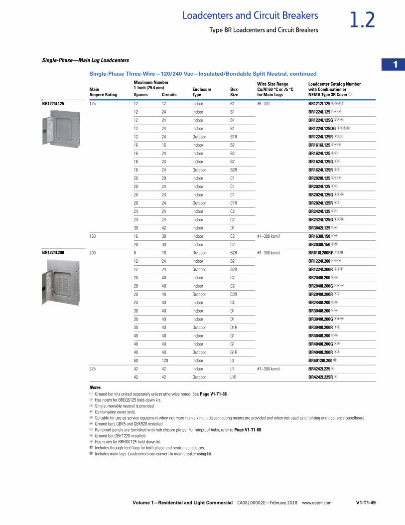
Volume 1—Residential and Light Commercial CA08100002E—February 2018 www.eaton.com V1-T1-49
1
1
1
1
1
1
1
1
1
1
1
1
1
1
1
1
1
1
1
1
1
1
1
1
1
1
1
1
1
1
1.2Loadcenters and Circuit Breakers
Type BR Loadcenters and Circuit Breakers
Single-Phase—Main Lug Loadcenters
Single-Phase Three-Wire—120/240 Vac—Insulated/Bondable Split Neutral, continued
Notes1 Ground bar kits priced separately unless otherwise noted. See Page V1-T1-68.2 Has notch for BREQS125 hold-down kit.3 Single, movable neutral is provided.4 Combination cover style.5 Suitable for use as service equipment when not more than six main disconnecting means are provided and when not used as a lighting and appliance panelboard.6 Ground bars GBK5 and GBK520 installed.7 Rainproof panels are furnished with hub closure plates. For rainproof hubs, refer to Page V1-T1-68.8 Ground bar GBK1220 installed.9 Has notch for BRHDK125 hold-down kit.j Includes through-feed lugs for both phase and neutral conductors.k Includes main lugs. Loadcenters can convert to main breaker using kit.
MainAmpere Rating
Maximum Number1-Inch (25.4 mm) Enclosure
TypeBoxSize
Wire Size RangeCu/Al 60 °C or 75 °Cfor Main Lugs
Loadcenter Catalog Numberwith Combination orNEMA Type 3R Cover 1Spaces Circuits
125 12 12 Indoor B1 #6–2/0 BR1212L125 2345
12 24 Indoor B1 BR1224L125 245
12 24 Indoor B1 BR1224L125G 245
12 24 Indoor B1 BR1224L125DG 2456
12 24 Outdoor B1R BR1224L125R 257
16 16 Indoor B2 BR1616L125 245
16 24 Indoor B2 BR1624L125 24
16 24 Indoor B2 BR1624L125G 24
16 24 Outdoor B2R BR1624L125R 27
20 20 Indoor C1 BR2020L125 245
20 24 Indoor C1 BR2024L125 24
20 24 Indoor C1 BR2024L125G 248
20 24 Outdoor C1R BR2024L125R 27
24 24 Indoor C2 BR2424L125 24
24 24 Indoor C2 BR2424L125G 248
30 42 Indoor D1 BR3042L125 24
150 16 30 Indoor C2 #1–300 kcmil BR1630L150 49
20 30 Indoor C2 BR2030L150 49
200 8 16 Outdoor B2R #1–300 kcmil BR816L200RF 57j
12 24 Indoor B2 BR1224L200 459
12 24 Outdoor B2R BR1224L200R 579
20 40 Indoor C2 BR2040L200 49
20 40 Indoor C2 BR2040L200G 489
20 40 Outdoor C3R BR2040L200R 79
24 40 Indoor C4 BR2440L200 49
30 40 Indoor D1 BR3040L200 49
30 40 Indoor D1 BR3040L200G 489
30 40 Outdoor D1R BR3040L200R 79
40 40 Indoor G1 BR4040L200 49
40 40 Indoor G1 BR4040L200G 49
40 40 Outdoor G1R BR4040L200R 79
60 120 Indoor L3 BR60120L200 k
225 42 42 Indoor L1 #1–300 kcmil BR4242L225 4
42 42 Outdoor L1R BR4242L225R 7
BR1224L125
BR1224L200
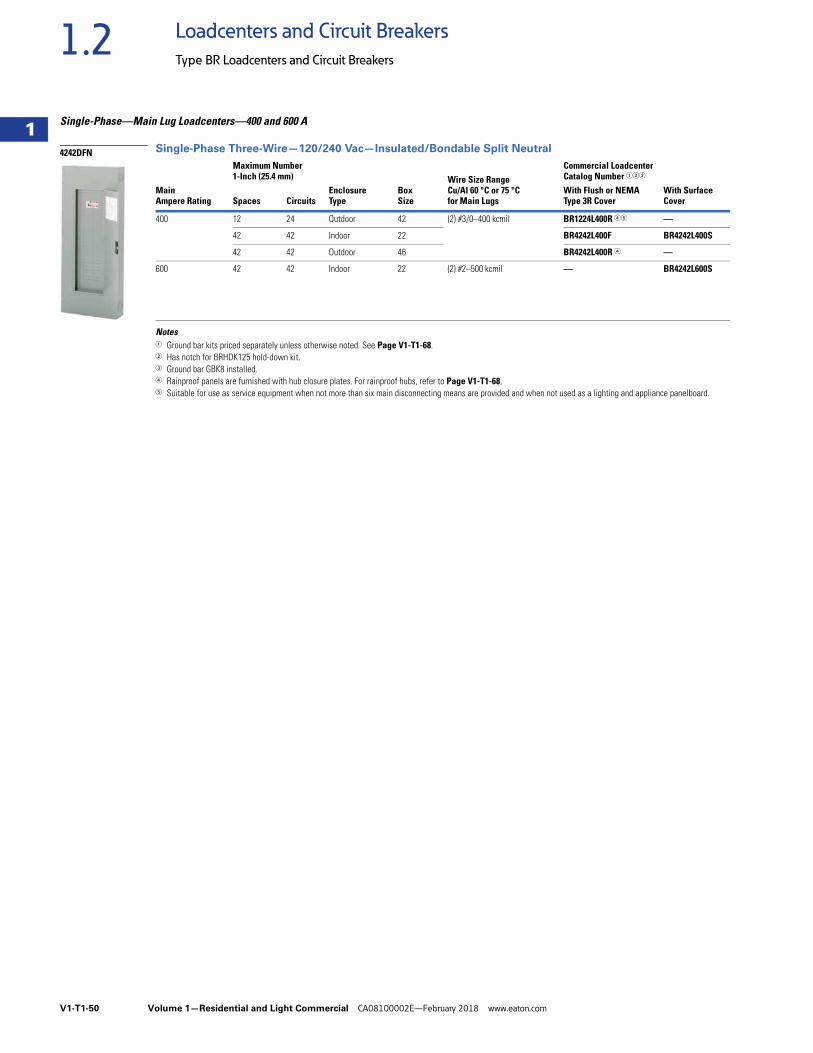
V1-T1-50 Volume 1—Residential and Light Commercial CA08100002E—February 2018 www.eaton.com
1
1
1
1
1
1
1
1
1
1
1
1
1
1
1
1
1
1
1
1
1
1
1
1
1
1
1
1
1
1
1.2 Loadcenters and Circuit Breakers
Type BR Loadcenters and Circuit Breakers
Single-Phase—Main Lug Loadcenters—400 and 600 A
Single-Phase Three-Wire—120/240 Vac—Insulated/Bondable Split Neutral
Notes1 Ground bar kits priced separately unless otherwise noted. See Page V1-T1-68.2 Has notch for BRHDK125 hold-down kit.3 Ground bar GBK8 installed.4 Rainproof panels are furnished with hub closure plates. For rainproof hubs, refer to Page V1-T1-68.5 Suitable for use as service equipment when not more than six main disconnecting means are provided and when not used as a lighting and appliance panelboard.
MainAmpere Rating
Maximum Number1-Inch (25.4 mm)
EnclosureType
BoxSize
Wire Size Range Cu/Al 60 °C or 75 °Cfor Main Lugs
Commercial LoadcenterCatalog Number 123
Spaces CircuitsWith Flush or NEMAType 3R Cover
With SurfaceCover
400 12 24 Outdoor 42 (2) #3/0–400 kcmil BR1224L400R 45 —
42 42 Indoor 22 BR4242L400F BR4242L400S
42 42 Outdoor 46 BR4242L400R 4 —
600 42 42 Indoor 22 (2) #2–500 kcmil — BR4242L600S
4242DFN
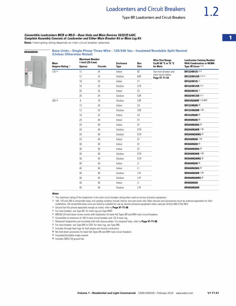
Volume 1—Residential and Light Commercial CA08100002E—February 2018 www.eaton.com V1-T1-51
1
1
1
1
1
1
1
1
1
1
1
1
1
1
1
1
1
1
1
1
1
1
1
1
1
1
1
1
1
1
1.2Loadcenters and Circuit Breakers
Type BR Loadcenters and Circuit Breakers
Convertible Loadcenters MCB or MLO—Base Units and Main Devices 10/22/25 kAIC, Complete Assembly Consists of: Loadcenter and Either Main Breaker Kit or Main Lug KitNote: Interrupting rating depends on main circuit breaker selected.
Base Units—Single-Phase Three-Wire—120/240 Vac—Insulated/Bondable Split Neutral (Unless Otherwise Noted)
Notes1 The maximum rating of the loadcenter is the main circuit breaker rating when used as service entrance equipment.2 100, 125 and 200 A convertible base unit catalog numbers include interior, box and cover only. Main devices and accessories must be ordered separately for field
installation. All convertible base units are listed as suitable for use as service entrance equipment when used per Article 408 of the NEC.3 Ground bar kits priced separately except as noted, refer to Page V1-T1-68.4 For main breaker, use Type BR. For main lug use Type BRSF.5 BREQS125 hold-down screw comes with loadcenter for back-fed Types BR and BRH main circuit breakers.6 Convertible to maximum of 100 A main circuit breaker and 125 A main lug.7 Rainproof loadcenters are furnished with hub closure plates. For rainproof hubs, refer to Page V1-T1-68.8 For main breaker, use Type BW or CSR. For main lug, use Type BRL.9 Includes through-feed lugs for both phase and neutral conductors.j No hold-down provisions for back-fed Types BR and BRH main circuit breakers.k Insulated/bondable single neutral.l Includes GBK2120 ground bar.
MainAmpere Rating 1
Maximum Number1-Inch (25.4 mm) Enclosure
TypeBoxSize
Wire Size RangeCu/Al 60 °C or 75 °Cfor Main
Loadcenter Catalog NumberWith Combination or NEMAType 3R Cover 23Spaces Circuits
125 4 12 24 Indoor B2 See main breaker andmain lug kit tablesPage V1-T1-54.
BR1224N125 56
12 24 Outdoor B2R BR1224N125R 567
16 24 Indoor C1 BR1624N125 5
16 24 Outdoor C1R BR1624N125R 57
20 24 Indoor C2 BR2024N125 5
20 24 Outdoor C3R BR2024N125R 57
200 8 8 16 Outdoor C3R BR816N200RF 79jk
12 24 Indoor C4 BR1224N200 j
12 24 Outdoor C3R BR1224N200R 7j
16 32 Indoor C4 BR1632N200 j
20 40 Indoor D1 BR2040N200 j
20 40 Indoor D1 BR2040N200G l
20 40 Outdoor D1R BR2040N200R 7j
20 40 Outdoor D1R BR2040N200RG l
24 40 Indoor G1 BR2440N200 7j
30 40 Indoor G1 BR3040N200 j
30 40 Indoor G1 BR3040N200G l
30 40 Outdoor G1R BR3040N200R 7j
30 40 Outdoor G1R BR3040N200RG l
40 40 Indoor L1 BR4040N200 j
40 40 Indoor L1 BR4040N200G l
40 40 Outdoor L1R BR4040N200R 7j
40 40 Outdoor L1R BR4040N200RG l
40 50 Indoor L1 BR4050N200
40 50 Outdoor L1R BR4050N200R
BR3040N200
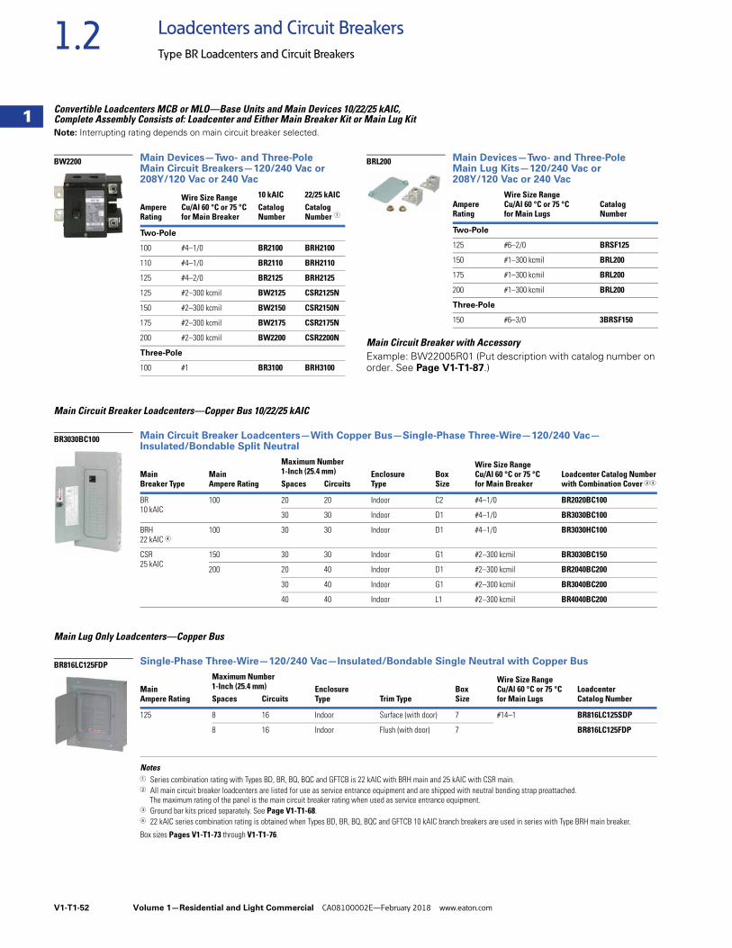
V1-T1-52 Volume 1—Residential and Light Commercial CA08100002E—February 2018 www.eaton.com
1
1
1
1
1
1
1
1
1
1
1
1
1
1
1
1
1
1
1
1
1
1
1
1
1
1
1
1
1
1
1.2 Loadcenters and Circuit Breakers
Type BR Loadcenters and Circuit Breakers
Convertible Loadcenters MCB or MLO—Base Units and Main Devices 10/22/25 kAIC, Complete Assembly Consists of: Loadcenter and Either Main Breaker Kit or Main Lug KitNote: Interrupting rating depends on main circuit breaker selected.
Main Devices—Two- and Three-Pole Main Circuit Breakers—120/240 Vac or 208Y/120 Vac or 240 Vac
Main Devices—Two- and Three-Pole Main Lug Kits—120/240 Vac or 208Y/120 Vac or 240 Vac
Main Circuit Breaker with AccessoryExample: BW22005R01 (Put description with catalog number on order. See Page V1-T1-87.)
Main Circuit Breaker Loadcenters—Copper Bus 10/22/25 kAIC
Main Circuit Breaker Loadcenters—With Copper Bus—Single-Phase Three-Wire—120/240 Vac—Insulated/Bondable Split Neutral
Main Lug Only Loadcenters—Copper Bus
Single-Phase Three-Wire—120/240 Vac—Insulated/Bondable Single Neutral with Copper Bus
Notes1 Series combination rating with Types BD, BR, BQ, BQC and GFTCB is 22 kAIC with BRH main and 25 kAIC with CSR main.2 All main circuit breaker loadcenters are listed for use as service entrance equipment and are shipped with neutral bonding strap preattached.
The maximum rating of the panel is the main circuit breaker rating when used as service entrance equipment.3 Ground bar kits priced separately. See Page V1-T1-68.4 22 kAIC series combination rating is obtained when Types BD, BR, BQ, BQC and GFTCB 10 kAIC branch breakers are used in series with Type BRH main breaker.
Box sizes Pages V1-T1-73 through V1-T1-76.
AmpereRating
Wire Size Range Cu/Al 60 °C or 75 °C for Main Breaker
10 kAIC 22/25 kAICCatalogNumber
CatalogNumber 1
Two-Pole
100 #4–1/0 BR2100 BRH2100
110 #4–1/0 BR2110 BRH2110
125 #4–2/0 BR2125 BRH2125
125 #2–300 kcmil BW2125 CSR2125N
150 #2–300 kcmil BW2150 CSR2150N
175 #2–300 kcmil BW2175 CSR2175N
200 #2–300 kcmil BW2200 CSR2200N
Three-Pole
100 #1 BR3100 BRH3100
BW2200
AmpereRating
Wire Size Range Cu/Al 60 °C or 75 °C for Main Lugs
CatalogNumber
Two-Pole
125 #6–2/0 BRSF125
150 #1–300 kcmil BRL200
175 #1–300 kcmil BRL200
200 #1–300 kcmil BRL200
Three-Pole
150 #6–3/0 3BRSF150
BRL200
MainBreaker Type
MainAmpere Rating
Maximum Number 1-Inch (25.4 mm) Enclosure
TypeBoxSize
Wire Size RangeCu/Al 60 °C or 75 °Cfor Main Breaker
Loadcenter Catalog Numberwith Combination Cover 23Spaces Circuits
BR10 kAIC
100 20 20 Indoor C2 #4–1/0 BR2020BC100
30 30 Indoor D1 #4–1/0 BR3030BC100
BRH22 kAIC 4
100 30 30 Indoor D1 #4–1/0 BR3030HC100
CSR25 kAIC
150 30 30 Indoor G1 #2–300 kcmil BR3030BC150
200 20 40 Indoor D1 #2–300 kcmil BR2040BC200
30 40 Indoor G1 #2–300 kcmil BR3040BC200
40 40 Indoor L1 #2–300 kcmil BR4040BC200
MainAmpere Rating
Maximum Number1-Inch (25.4 mm) Enclosure
Type Trim TypeBoxSize
Wire Size RangeCu/Al 60 °C or 75 °Cfor Main Lugs
LoadcenterCatalog NumberSpaces Circuits
125 8 16 Indoor Surface (with door) 7 #14–1 BR816LC125SDP
8 16 Indoor Flush (with door) 7 BR816LC125FDP
BR3030BC100
BR816LC125FDP
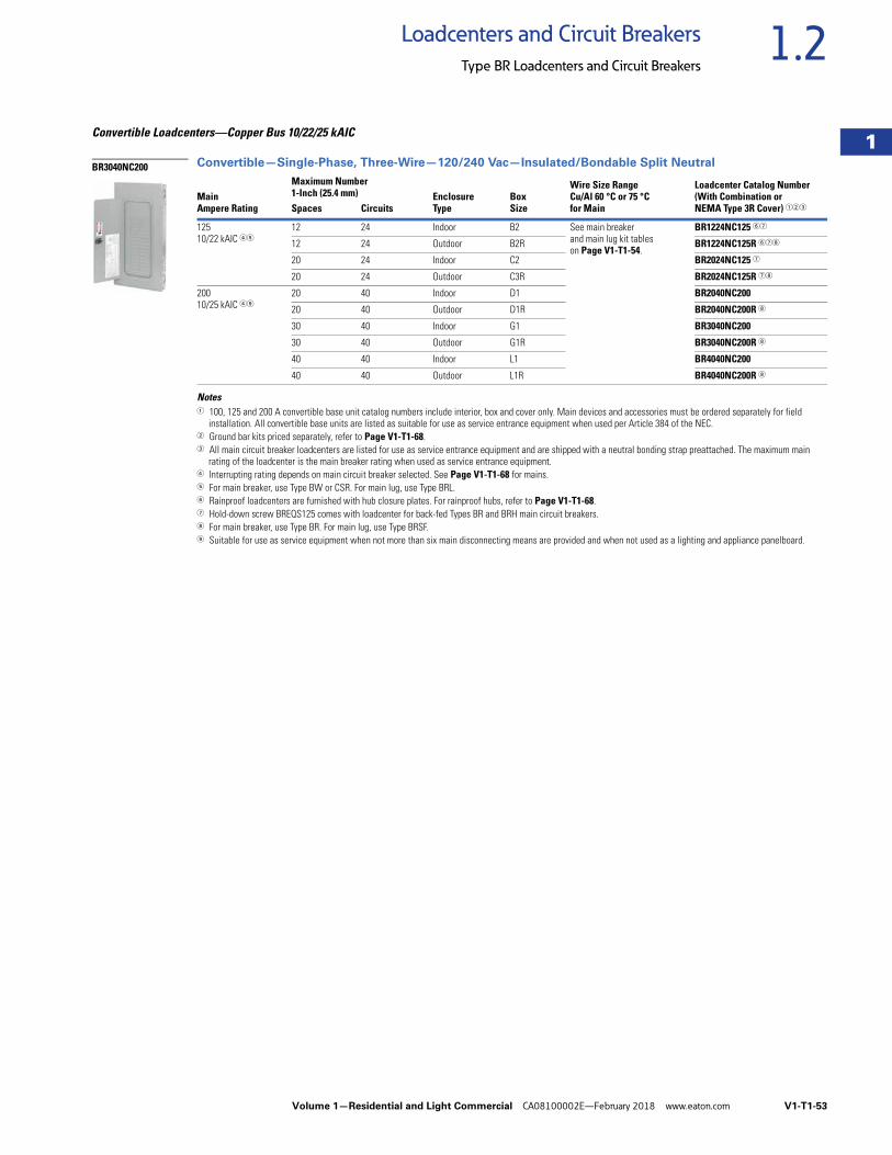
Volume 1—Residential and Light Commercial CA08100002E—February 2018 www.eaton.com V1-T1-53
1
1
1
1
1
1
1
1
1
1
1
1
1
1
1
1
1
1
1
1
1
1
1
1
1
1
1
1
1
1
1.2Loadcenters and Circuit Breakers
Type BR Loadcenters and Circuit Breakers
Convertible Loadcenters—Copper Bus 10/22/25 kAIC
Convertible—Single-Phase, Three-Wire—120/240 Vac—Insulated/Bondable Split Neutral
Notes1 100, 125 and 200 A convertible base unit catalog numbers include interior, box and cover only. Main devices and accessories must be ordered separately for field
installation. All convertible base units are listed as suitable for use as service entrance equipment when used per Article 384 of the NEC.2 Ground bar kits priced separately, refer to Page V1-T1-68.3 All main circuit breaker loadcenters are listed for use as service entrance equipment and are shipped with a neutral bonding strap preattached. The maximum main
rating of the loadcenter is the main breaker rating when used as service entrance equipment.4 Interrupting rating depends on main circuit breaker selected. See Page V1-T1-68 for mains.5 For main breaker, use Type BW or CSR. For main lug, use Type BRL.6 Rainproof loadcenters are furnished with hub closure plates. For rainproof hubs, refer to Page V1-T1-68.7 Hold-down screw BREQS125 comes with loadcenter for back-fed Types BR and BRH main circuit breakers.8 For main breaker, use Type BR. For main lug, use Type BRSF.9 Suitable for use as service equipment when not more than six main disconnecting means are provided and when not used as a lighting and appliance panelboard.
MainAmpere Rating
Maximum Number1-Inch (25.4 mm) Enclosure
TypeBoxSize
Wire Size RangeCu/Al 60 °C or 75 °Cfor Main
Loadcenter Catalog Number(With Combination orNEMA Type 3R Cover) 123Spaces Circuits
12510/22 kAIC 45
12 24 Indoor B2 See main breaker and main lug kit tables on Page V1-T1-54.
BR1224NC125 67
12 24 Outdoor B2R BR1224NC125R 678
20 24 Indoor C2 BR2024NC125 7
20 24 Outdoor C3R BR2024NC125R 78
20010/25 kAIC 49
20 40 Indoor D1 BR2040NC200
20 40 Outdoor D1R BR2040NC200R 8
30 40 Indoor G1 BR3040NC200
30 40 Outdoor G1R BR3040NC200R 8
40 40 Indoor L1 BR4040NC200
40 40 Outdoor L1R BR4040NC200R 8
BR3040NC200
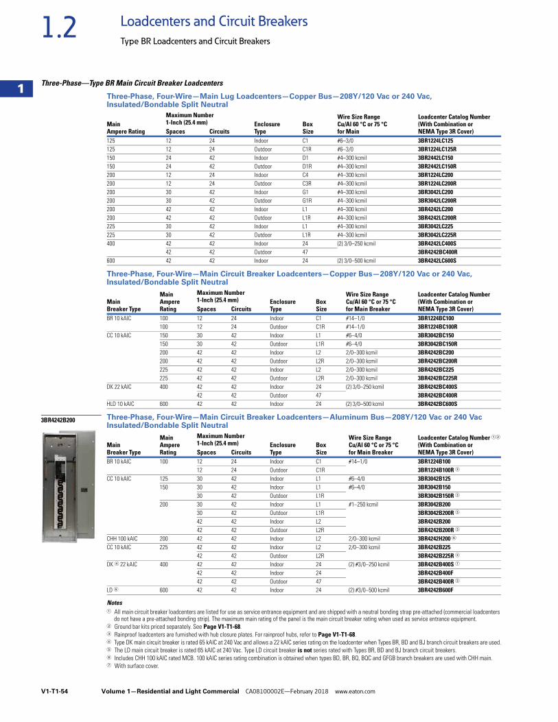
V1-T1-54 Volume 1—Residential and Light Commercial CA08100002E—February 2018 www.eaton.com
1
1
1
1
1
1
1
1
1
1
1
1
1
1
1
1
1
1
1
1
1
1
1
1
1
1
1
1
1
1
1.2 Loadcenters and Circuit Breakers
Type BR Loadcenters and Circuit Breakers
Three-Phase—Type BR Main Circuit Breaker Loadcenters
Three-Phase, Four-Wire—Main Lug Loadcenters—Copper Bus—208Y/120 Vac or 240 Vac, Insulated/Bondable Split Neutral
Three-Phase, Four-Wire—Main Circuit Breaker Loadcenters—Copper Bus—208Y/120 Vac or 240 Vac, Insulated/Bondable Split Neutral
Three-Phase, Four-Wire—Main Circuit Breaker Loadcenters—Aluminum Bus—208Y/120 Vac or 240 Vac Insulated/Bondable Split Neutral
Notes1 All main circuit breaker loadcenters are listed for use as service entrance equipment and are shipped with a neutral bonding strap pre-attached (commercial loadcenters
do not have a pre-attached bonding strip). The maximum main rating of the panel is the main circuit breaker rating when used as service entrance equipment.2 Ground bar kits priced separately. See Page V1-T1-68.3 Rainproof loadcenters are furnished with hub closure plates. For rainproof hubs, refer to Page V1-T1-68.4 Type DK main circuit breaker is rated 65 kAIC at 240 Vac and allows a 22 kAIC series rating on the loadcenter when Types BR, BD and BJ branch circuit breakers are used.5 The LD main circuit breaker is rated 65 kAIC at 240 Vac. Type LD circuit breaker is not series rated with Types BR, BD and BJ branch circuit breakers.6 Includes CHH 100 kAIC rated MCB. 100 kAIC series rating combination is obtained when types BD, BR, BQ, BQC and GFGB branch breakers are used with CHH main.7 With surface cover.
MainAmpere Rating
Maximum Number1-Inch (25.4 mm) Enclosure
TypeBoxSize
Wire Size RangeCu/Al 60 °C or 75 °Cfor Main
Loadcenter Catalog Number(With Combination orNEMA Type 3R Cover)Spaces Circuits
125 12 24 Indoor C1 #6–3/0 3BR1224LC125125 12 24 Outdoor C1R #6–3/0 3BR1224LC125R150 24 42 Indoor D1 #4–300 kcmil 3BR2442LC150150 24 42 Outdoor D1R #4–300 kcmil 3BR2442LC150R200 12 24 Indoor C4 #4–300 kcmil 3BR1224LC200200 12 24 Outdoor C3R #4–300 kcmil 3BR1224LC200R200 30 42 Indoor G1 #4–300 kcmil 3BR3042LC200200 30 42 Outdoor G1R #4–300 kcmil 3BR3042LC200R200 42 42 Indoor L1 #4–300 kcmil 3BR4242LC200200 42 42 Outdoor L1R #4–300 kcmil 3BR4242LC200R225 30 42 Indoor L1 #4–300 kcmil 3BR3042LC225225 30 42 Outdoor L1R #4–300 kcmil 3BR3042LC225R400 42 42 Indoor 24 (2) 3/0–250 kcmil 3BR4242LC400S
42 42 Outdoor 47 3BR4242BC400R600 42 42 Indoor 24 (2) 3/0–500 kcmil 3BR4242LC600S
MainBreaker Type
MainAmpereRating
Maximum Number1-Inch (25.4 mm) Enclosure
TypeBoxSize
Wire Size RangeCu/Al 60 °C or 75 °Cfor Main Breaker
Loadcenter Catalog Number (With Combination orNEMA Type 3R Cover)Spaces Circuits
BR 10 kAIC 100 12 24 Indoor C1 #14–1/0 3BR1224BC100100 12 24 Outdoor C1R #14–1/0 3BR1224BC100R
CC 10 kAIC 150 30 42 Indoor L1 #6–4/0 3BR3042BC150150 30 42 Outdoor L1R #6–4/0 3BR3042BC150R200 42 42 Indoor L2 2/0–300 kcmil 3BR4242BC200200 42 42 Outdoor L2R 2/0–300 kcmil 3BR4242BC200R225 42 42 Indoor L2 2/0–300 kcmil 3BR4242BC225225 42 42 Outdoor L2R 2/0–300 kcmil 3BR4242BC225R
DK 22 kAIC 400 42 42 Indoor 24 (2) 3/0–250 kcmil 3BR4242BC400S42 42 Outdoor 47 3BR4242BC400R
HLD 10 kAIC 600 42 42 Indoor 24 (2) 3/0–500 kcmil 3BR4242BC600S
MainBreaker Type
MainAmpereRating
Maximum Number1-Inch (25.4 mm) Enclosure
TypeBoxSize
Wire Size RangeCu/Al 60 °C or 75 °Cfor Main Breaker
Loadcenter Catalog Number 12
(With Combination orNEMA Type 3R Cover)Spaces Circuits
BR 10 kAIC 100 12 24 Indoor C1 #14–1/0 3BR1224B10012 24 Outdoor C1R 3BR1224B100R 3
CC 10 kAIC 125 30 42 Indoor L1 #6–4/0 3BR3042B125150 30 42 Indoor L1 #6–4/0 3BR3042B150
30 42 Outdoor L1R 3BR3042B150R 3
200 30 42 Indoor L1 #1–250 kcmil 3BR3042B20030 42 Outdoor L1R 3BR3042B200R 3
42 42 Indoor L2 3BR4242B20042 42 Outdoor L2R 3BR4242B200R 3
CHH 100 kAIC 200 42 42 Indoor L2 2/0–300 kcmil 3BR4242H200 6
CC 10 kAIC 225 42 42 Indoor L2 2/0–300 kcmil 3BR4242B22542 42 Outdoor L2R 3BR4242B225R 3
DK 4 22 kAIC 400 42 42 Indoor 24 (2) #3/0–250 kcmil 3BR4242B400S 7
42 42 Indoor 24 3BR4242B400F42 42 Outdoor 47 3BR4242B400R 3
LD 5 600 42 42 Indoor 24 (2) #3/0–500 kcmil 3BR4242B600F
3BR4242B200
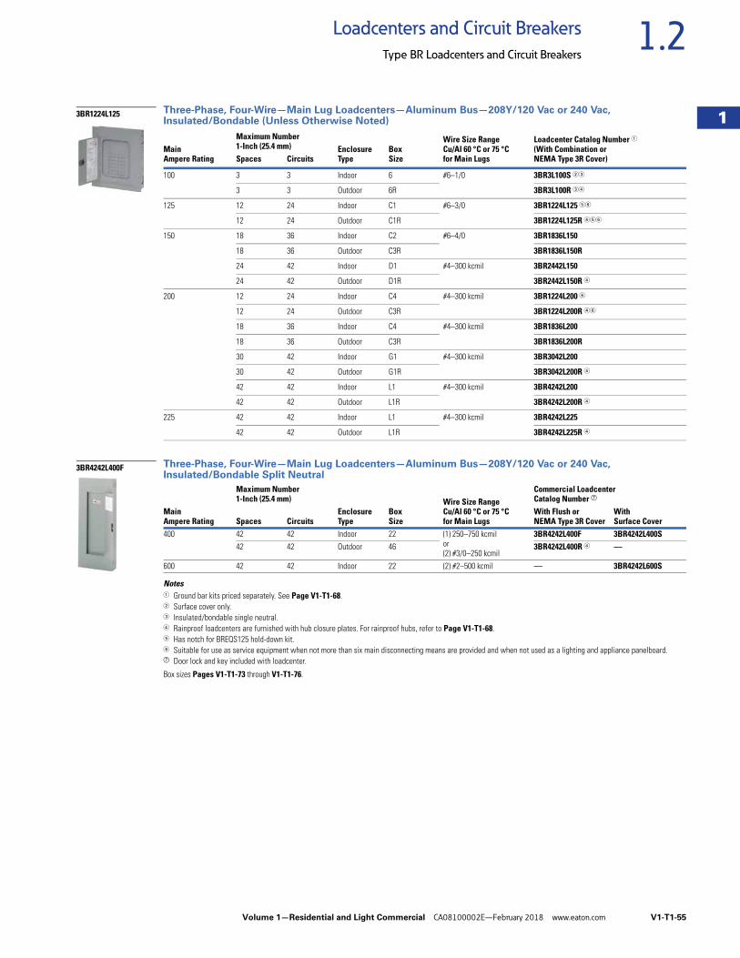
Volume 1—Residential and Light Commercial CA08100002E—February 2018 www.eaton.com V1-T1-55
1
1
1
1
1
1
1
1
1
1
1
1
1
1
1
1
1
1
1
1
1
1
1
1
1
1
1
1
1
1
1.2Loadcenters and Circuit Breakers
Type BR Loadcenters and Circuit Breakers
Three-Phase, Four-Wire—Main Lug Loadcenters—Aluminum Bus—208Y/120 Vac or 240 Vac, Insulated/Bondable (Unless Otherwise Noted)
Three-Phase, Four-Wire—Main Lug Loadcenters—Aluminum Bus—208Y/120 Vac or 240 Vac, Insulated/Bondable Split Neutral
Notes1 Ground bar kits priced separately. See Page V1-T1-68.2 Surface cover only.3 Insulated/bondable single neutral.4 Rainproof loadcenters are furnished with hub closure plates. For rainproof hubs, refer to Page V1-T1-68.5 Has notch for BREQS125 hold-down kit.6 Suitable for use as service equipment when not more than six main disconnecting means are provided and when not used as a lighting and appliance panelboard.g Door lock and key included with loadcenter.
Box sizes Pages V1-T1-73 through V1-T1-76.
MainAmpere Rating
Maximum Number1-Inch (25.4 mm) Enclosure
TypeBoxSize
Wire Size RangeCu/Al 60 °C or 75 °Cfor Main Lugs
Loadcenter Catalog Number 1(With Combination orNEMA Type 3R Cover)Spaces Circuits
100 3 3 Indoor 6 #6–1/0 3BR3L100S 23
3 3 Outdoor 6R 3BR3L100R 34
125 12 24 Indoor C1 #6–3/0 3BR1224L125 56
12 24 Outdoor C1R 3BR1224L125R 456
150 18 36 Indoor C2 #6–4/0 3BR1836L150
18 36 Outdoor C3R 3BR1836L150R
24 42 Indoor D1 #4–300 kcmil 3BR2442L150
24 42 Outdoor D1R 3BR2442L150R 4
200 12 24 Indoor C4 #4–300 kcmil 3BR1224L200 6
12 24 Outdoor C3R 3BR1224L200R 46
18 36 Indoor C4 #4–300 kcmil 3BR1836L200
18 36 Outdoor C3R 3BR1836L200R
30 42 Indoor G1 #4–300 kcmil 3BR3042L200
30 42 Outdoor G1R 3BR3042L200R 4
42 42 Indoor L1 #4–300 kcmil 3BR4242L200
42 42 Outdoor L1R 3BR4242L200R 4
225 42 42 Indoor L1 #4–300 kcmil 3BR4242L225
42 42 Outdoor L1R 3BR4242L225R 4
MainAmpere Rating
Maximum Number1-Inch (25.4 mm)
EnclosureType
BoxSize
Wire Size RangeCu/Al 60 °C or 75 °Cfor Main Lugs
Commercial LoadcenterCatalog Number g
Spaces CircuitsWith Flush or NEMA Type 3R Cover
With Surface Cover
400 42 42 Indoor 22 (1) 250–750 kcmilor(2) #3/0–250 kcmil
3BR4242L400F 3BR4242L400S42 42 Outdoor 46 3BR4242L400R 4 —
600 42 42 Indoor 22 (2) #2–500 kcmil — 3BR4242L600S
3BR1224L125
3BR4242L400F
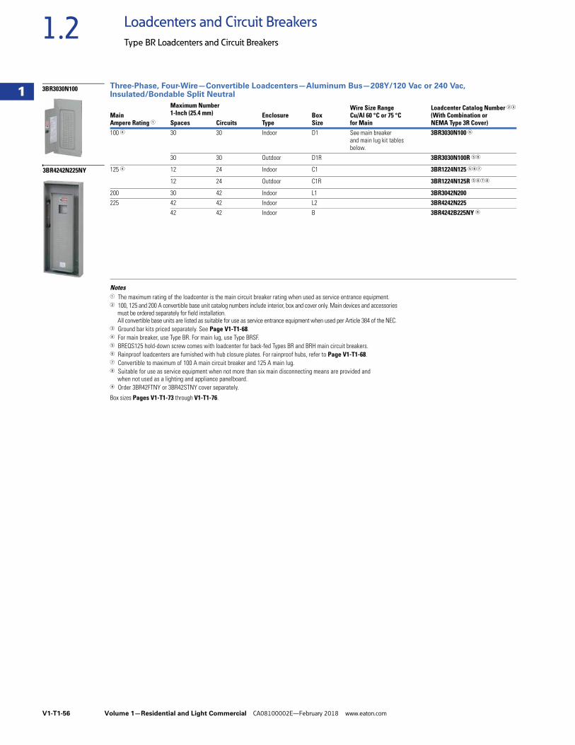
V1-T1-56 Volume 1—Residential and Light Commercial CA08100002E—February 2018 www.eaton.com
1
1
1
1
1
1
1
1
1
1
1
1
1
1
1
1
1
1
1
1
1
1
1
1
1
1
1
1
1
1
1.2 Loadcenters and Circuit Breakers
Type BR Loadcenters and Circuit Breakers
Three-Phase, Four-Wire—Convertible Loadcenters—Aluminum Bus—208Y/120 Vac or 240 Vac, Insulated/Bondable Split Neutral
Notes1 The maximum rating of the loadcenter is the main circuit breaker rating when used as service entrance equipment.2 100, 125 and 200 A convertible base unit catalog numbers include interior, box and cover only. Main devices and accessories
must be ordered separately for field installation. All convertible base units are listed as suitable for use as service entrance equipment when used per Article 384 of the NEC.
3 Ground bar kits priced separately. See Page V1-T1-68.4 For main breaker, use Type BR. For main lug, use Type BRSF.5 BREQS125 hold-down screw comes with loadcenter for back-fed Types BR and BRH main circuit breakers.6 Rainproof loadcenters are furnished with hub closure plates. For rainproof hubs, refer to Page V1-T1-68.7 Convertible to maximum of 100 A main circuit breaker and 125 A main lug.8 Suitable for use as service equipment when not more than six main disconnecting means are provided and
when not used as a lighting and appliance panelboard.9 Order 3BR42FTNY or 3BR42STNY cover separately.
Box sizes Pages V1-T1-73 through V1-T1-76.
MainAmpere Rating 1
Maximum Number1-Inch (25.4 mm) Enclosure
TypeBoxSize
Wire Size RangeCu/Al 60 °C or 75 °Cfor Main
Loadcenter Catalog Number 23
(With Combination orNEMA Type 3R Cover)Spaces Circuits
100 4 30 30 Indoor D1 See main breaker and main lug kit tables below.
3BR3030N100 5
30 30 Outdoor D1R 3BR3030N100R 56
125 4 12 24 Indoor C1 3BR1224N125 567
12 24 Outdoor C1R 3BR1224N125R 5678
200 30 42 Indoor L1 3BR3042N200225 42 42 Indoor L2 3BR4242N225
42 42 Indoor B 3BR4242B225NY 9
3BR3030N100
3BR4242N225NY
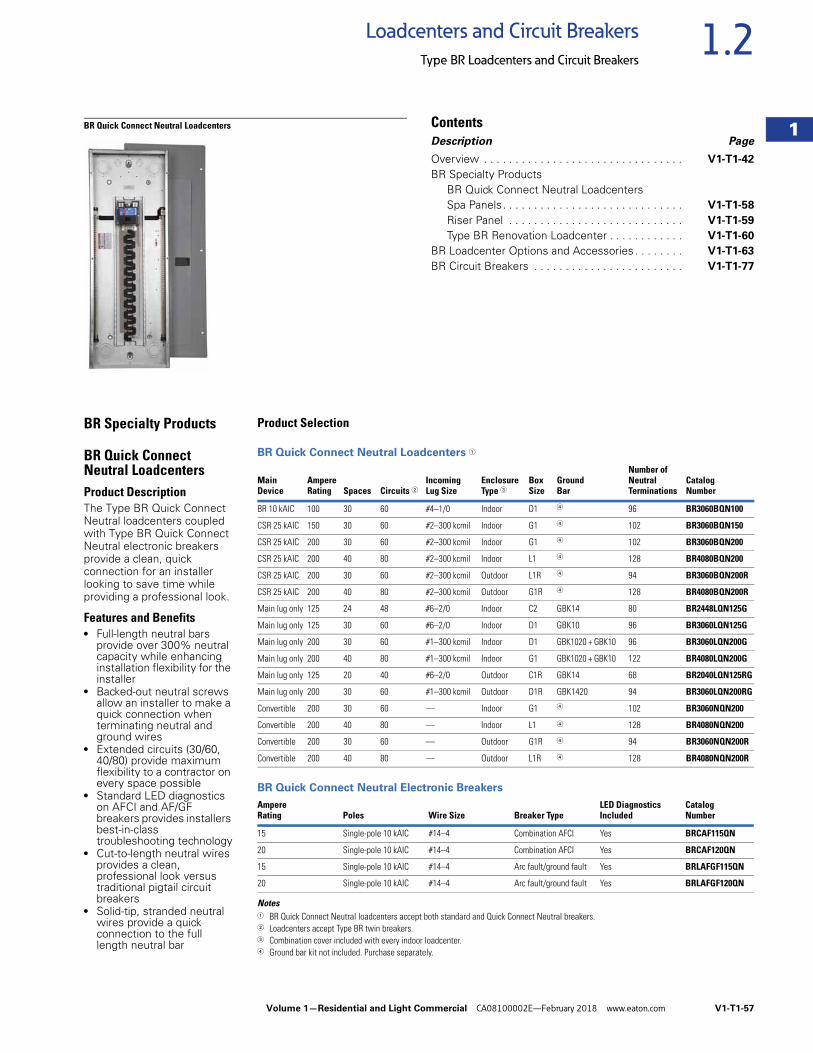
Volume 1—Residential and Light Commercial CA08100002E—February 2018 www.eaton.com V1-T1-57
1
1
1
1
1
1
1
1
1
1
1
1
1
1
1
1
1
1
1
1
1
1
1
1
1
1
1
1
1
1
1.2Loadcenters and Circuit Breakers
Type BR Loadcenters and Circuit Breakers
BR Quick Connect Neutral Loadcenters ContentsDescription Page
Overview . . . . . . . . . . . . . . . . . . . . . . . . . . . . . . . . V1-T1-42
BR Specialty ProductsBR Quick Connect Neutral LoadcentersSpa Panels. . . . . . . . . . . . . . . . . . . . . . . . . . . . . V1-T1-58
Riser Panel . . . . . . . . . . . . . . . . . . . . . . . . . . . . V1-T1-59
Type BR Renovation Loadcenter . . . . . . . . . . . . V1-T1-60
BR Loadcenter Options and Accessories . . . . . . . . V1-T1-63
BR Circuit Breakers . . . . . . . . . . . . . . . . . . . . . . . . V1-T1-77
BR Specialty Products
BR Quick Connect Neutral LoadcentersProduct DescriptionThe Type BR Quick Connect Neutral loadcenters coupled with Type BR Quick Connect Neutral electronic breakers provide a clean, quick connection for an installer looking to save time while providing a professional look.
Features and Benefits● Full-length neutral bars
provide over 300% neutral capacity while enhancing installation flexibility for the installer
● Backed-out neutral screws allow an installer to make a quick connection when terminating neutral and ground wires
● Extended circuits (30/60, 40/80) provide maximum flexibility to a contractor on every space possible
● Standard LED diagnostics on AFCI and AF/GF breakers provides installers best-in-class troubleshooting technology
● Cut-to-length neutral wires provides a clean, professional look versus traditional pigtail circuit breakers
● Solid-tip, stranded neutral wires provide a quick connection to the full length neutral bar
Product Selection
BR Quick Connect Neutral Loadcenters 1
BR Quick Connect Neutral Electronic Breakers
Notes1 BR Quick Connect Neutral loadcenters accept both standard and Quick Connect Neutral breakers.2 Loadcenters accept Type BR twin breakers. 3 Combination cover included with every indoor loadcenter. 4 Ground bar kit not included. Purchase separately.
Main Device
AmpereRating Spaces Circuits 2
Incoming Lug Size
Enclosure Type 3
Box Size
Ground Bar
Number of Neutral Terminations
Catalog Number
BR 10 kAIC 100 30 60 #4–1/0 Indoor D1 4 96 BR3060BQN100
CSR 25 kAIC 150 30 60 #2–300 kcmil Indoor G1 4 102 BR3060BQN150
CSR 25 kAIC 200 30 60 #2–300 kcmil Indoor G1 4 102 BR3060BQN200
CSR 25 kAIC 200 40 80 #2–300 kcmil Indoor L1 4 128 BR4080BQN200
CSR 25 kAIC 200 30 60 #2–300 kcmil Outdoor L1R 4 94 BR3060BQN200R
CSR 25 kAIC 200 40 80 #2–300 kcmil Outdoor G1R 4 128 BR4080BQN200R
Main lug only 125 24 48 #6–2/0 Indoor C2 GBK14 80 BR2448LQN125G
Main lug only 125 30 60 #6–2/0 Indoor D1 GBK10 96 BR3060LQN125G
Main lug only 200 30 60 #1–300 kcmil Indoor D1 GBK1020 + GBK10 96 BR3060LQN200G
Main lug only 200 40 80 #1–300 kcmil Indoor G1 GBK1020 + GBK10 122 BR4080LQN200G
Main lug only 125 20 40 #6–2/0 Outdoor C1R GBK14 68 BR2040LQN125RG
Main lug only 200 30 60 #1–300 kcmil Outdoor D1R GBK1420 94 BR3060LQN200RG
Convertible 200 30 60 — Indoor G1 4 102 BR3060NQN200
Convertible 200 40 80 — Indoor L1 4 128 BR4080NQN200
Convertible 200 30 60 — Outdoor G1R 4 94 BR3060NQN200R
Convertible 200 40 80 — Outdoor L1R 4 128 BR4080NQN200R
AmpereRating Poles Wire Size Breaker Type
LED DiagnosticsIncluded
Catalog Number
15 Single-pole 10 kAIC #14–4 Combination AFCI Yes BRCAF115QN
20 Single-pole 10 kAIC #14–4 Combination AFCI Yes BRCAF120QN
15 Single-pole 10 kAIC #14–4 Arc fault/ground fault Yes BRLAFGF115QN
20 Single-pole 10 kAIC #14–4 Arc fault/ground fault Yes BRLAFGF120QN
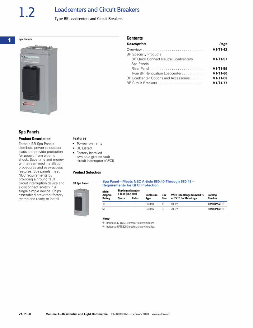
V1-T1-58 Volume 1—Residential and Light Commercial CA08100002E—February 2018 www.eaton.com
1
1
1
1
1
1
1
1
1
1
1
1
1
1
1
1
1
1
1
1
1
1
1
1
1
1
1
1
1
1
1.2 Loadcenters and Circuit Breakers
Type BR Loadcenters and Circuit Breakers
Spa Panels ContentsDescription Page
Overview . . . . . . . . . . . . . . . . . . . . . . . . . . . . . . . . V1-T1-42
BR Specialty ProductsBR Quick Connect Neutral Loadcenters . . . . . . V1-T1-57
Spa PanelsRiser Panel . . . . . . . . . . . . . . . . . . . . . . . . . . . . V1-T1-59
Type BR Renovation Loadcenter . . . . . . . . . . . . V1-T1-60
BR Loadcenter Options and Accessories. . . . . . . . V1-T1-63
BR Circuit Breakers . . . . . . . . . . . . . . . . . . . . . . . . V1-T1-77
Spa PanelsProduct DescriptionEaton’s BR Spa Panels distribute power to outdoor loads and provide protection for people from electric shock. Save time and money with streamlined installation procedures and easy-access features. Spa panels meet NEC requirements by providing a ground fault circuit interruption device and a disconnect switch in a single simple device. Ships assembled prewired, factory tested and ready to install.
Features● 10-year warranty ● UL Listed ● Factory-installed
two-pole ground fault circuit interrupter (GFCI)
Product Selection
Spa Panel—Meets NEC Article 680.40 Through 680.43—Requirements for GFCI Protection
Notes1 Includes a GFTCB240 breaker, factory installed.2 Includes a GFTCB250 breaker, factory installed.
MainAmpere Rating
Maximum Number1-Inch (25.4 mm) Enclosure
TypeBoxSize
Wire Size Range Cu/Al 60 °C or 75 °C for Main Lugs
CatalogNumberSpace Poles
40 — — Outdoor 5R #8–#2 BR40SPAST 1
50 — — Outdoor 5R #8–#2 BR50SPAST 2
BR Spa Panel
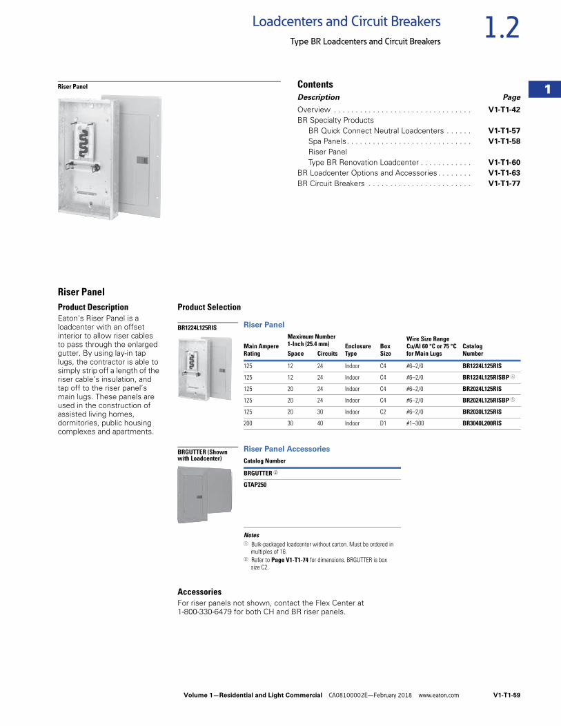
Volume 1—Residential and Light Commercial CA08100002E—February 2018 www.eaton.com V1-T1-59
1
1
1
1
1
1
1
1
1
1
1
1
1
1
1
1
1
1
1
1
1
1
1
1
1
1
1
1
1
1
1.2Loadcenters and Circuit Breakers
Type BR Loadcenters and Circuit Breakers
Riser Panel ContentsDescription Page
Overview . . . . . . . . . . . . . . . . . . . . . . . . . . . . . . . . V1-T1-42
BR Specialty ProductsBR Quick Connect Neutral Loadcenters . . . . . . V1-T1-57
Spa Panels. . . . . . . . . . . . . . . . . . . . . . . . . . . . . V1-T1-58
Riser PanelType BR Renovation Loadcenter . . . . . . . . . . . . V1-T1-60
BR Loadcenter Options and Accessories . . . . . . . . V1-T1-63
BR Circuit Breakers . . . . . . . . . . . . . . . . . . . . . . . . V1-T1-77
Riser PanelProduct DescriptionEaton’s Riser Panel is a loadcenter with an offset interior to allow riser cables to pass through the enlarged gutter. By using lay-in tap lugs, the contractor is able to simply strip off a length of the riser cable’s insulation, and tap off to the riser panel’s main lugs. These panels are used in the construction of assisted living homes, dormitories, public housing complexes and apartments.
Product Selection
Riser Panel
Riser Panel Accessories
Notes1 Bulk-packaged loadcenter without carton. Must be ordered in
multiples of 16.2 Refer to Page V1-T1-74 for dimensions. BRGUTTER is box
size C2.
AccessoriesFor riser panels not shown, contact the Flex Center at 1-800-330-6479 for both CH and BR riser panels.
Main AmpereRating
Maximum Number1-Inch (25.4 mm) Enclosure
TypeBoxSize
Wire Size RangeCu/Al 60 °C or 75 °Cfor Main Lugs
CatalogNumberSpace Circuits
125 12 24 Indoor C4 #6–2/0 BR1224L125RIS
125 12 24 Indoor C4 #6–2/0 BR1224L125RISBP 1
125 20 24 Indoor C4 #6–2/0 BR2024L125RIS
125 20 24 Indoor C4 #6–2/0 BR2024L125RISBP 1
125 20 30 Indoor C2 #6–2/0 BR2030L125RIS
200 30 40 Indoor D1 #1–300 BR3040L200RIS
Catalog Number
BRGUTTER 2
GTAP250
BR1224L125RIS
BRGUTTER (Shown with Loadcenter)
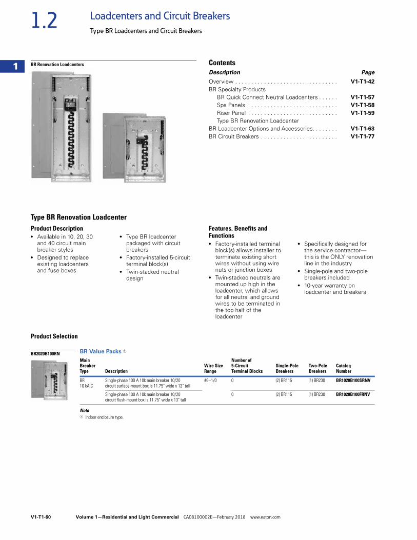
V1-T1-60 Volume 1—Residential and Light Commercial CA08100002E—February 2018 www.eaton.com
1
1
1
1
1
1
1
1
1
1
1
1
1
1
1
1
1
1
1
1
1
1
1
1
1
1
1
1
1
1
1.2 Loadcenters and Circuit Breakers
Type BR Loadcenters and Circuit Breakers
BR Renovation Loadcenters ContentsDescription Page
Overview . . . . . . . . . . . . . . . . . . . . . . . . . . . . . . . . V1-T1-42
BR Specialty ProductsBR Quick Connect Neutral Loadcenters . . . . . . V1-T1-57
Spa Panels . . . . . . . . . . . . . . . . . . . . . . . . . . . . V1-T1-58
Riser Panel . . . . . . . . . . . . . . . . . . . . . . . . . . . . V1-T1-59
Type BR Renovation LoadcenterBR Loadcenter Options and Accessories. . . . . . . . V1-T1-63
BR Circuit Breakers . . . . . . . . . . . . . . . . . . . . . . . . V1-T1-77
Type BR Renovation Loadcenter Product Description● Available in 10, 20, 30
and 40 circuit main breaker styles
● Designed to replace existing loadcenters and fuse boxes
● Type BR loadcenter packaged with circuit breakers
● Factory-installed 5-circuit terminal block(s)
● Twin-stacked neutral design
Features, Benefits and Functions ● Factory-installed terminal
block(s) allows installer to terminate existing short wires without using wire nuts or junction boxes
● Twin-stacked neutrals are mounted up high in the loadcenter, which allows for all neutral and ground wires to be terminated in the top half of the loadcenter
● Specifically designed for the service contractor—this is the ONLY renovation line in the industry
● Single-pole and two-pole breakers included
● 10-year warranty on loadcenter and breakers
Product Selection
BR Value Packs 1
Note1 Indoor enclosure type.
MainBreakerType Description
Wire SizeRange
Number of 5-CircuitTerminal Blocks
Single-Pole Breakers
Two-PoleBreakers
CatalogNumber
BR10 kAIC
Single-phase 100 A 10k main breaker 10/20 circuit surface-mount box is 11.75" wide x 13" tall
#6–1/0 0 (2) BR115 (1) BR230 BR1020B100SRNV
Single-phase 100 A 10k main breaker 10/20circuit flush-mount box is 11.75" wide x 13" tall
0 (2) BR115 (1) BR230 BR1020B100FRNV
BR2020B100RN
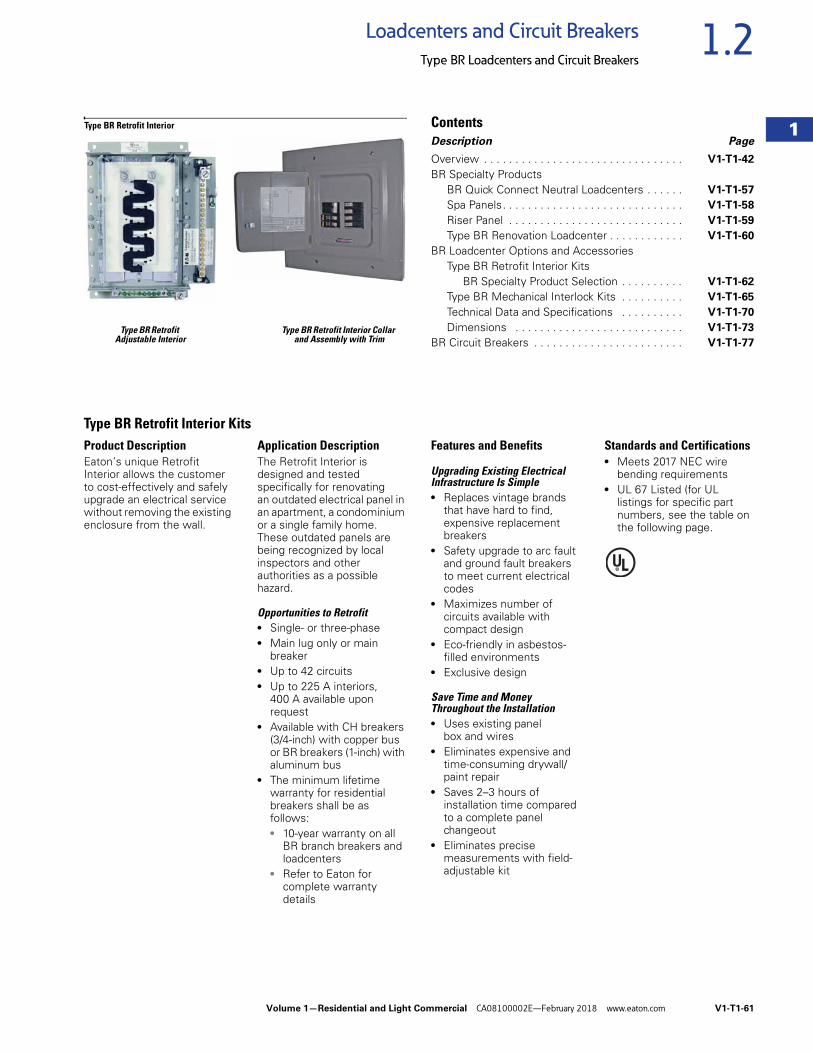
Volume 1—Residential and Light Commercial CA08100002E—February 2018 www.eaton.com V1-T1-61
1
1
1
1
1
1
1
1
1
1
1
1
1
1
1
1
1
1
1
1
1
1
1
1
1
1
1
1
1
1
1.2Loadcenters and Circuit Breakers
Type BR Loadcenters and Circuit Breakers
Type BR Retrofit Type BR Retrofit Interior Collar Adjustable Interior and Assembly with Trim
Type BR Retrofit Interior ContentsDescription Page
Overview . . . . . . . . . . . . . . . . . . . . . . . . . . . . . . . . V1-T1-42
BR Specialty ProductsBR Quick Connect Neutral Loadcenters . . . . . . V1-T1-57
Spa Panels. . . . . . . . . . . . . . . . . . . . . . . . . . . . . V1-T1-58
Riser Panel . . . . . . . . . . . . . . . . . . . . . . . . . . . . V1-T1-59
Type BR Renovation Loadcenter . . . . . . . . . . . . V1-T1-60
BR Loadcenter Options and AccessoriesType BR Retrofit Interior Kits
BR Specialty Product Selection . . . . . . . . . . V1-T1-62
Type BR Mechanical Interlock Kits . . . . . . . . . . V1-T1-65
Technical Data and Specifications . . . . . . . . . . V1-T1-70
Dimensions . . . . . . . . . . . . . . . . . . . . . . . . . . . V1-T1-73
BR Circuit Breakers . . . . . . . . . . . . . . . . . . . . . . . . V1-T1-77
Type BR Retrofit Interior KitsProduct DescriptionEaton’s unique Retrofit Interior allows the customer to cost-effectively and safely upgrade an electrical service without removing the existing enclosure from the wall.
Application DescriptionThe Retrofit Interior is designed and tested specifically for renovating an outdated electrical panel in an apartment, a condominium or a single family home. These outdated panels are being recognized by local inspectors and other authorities as a possible hazard.
Opportunities to Retrofit● Single- or three-phase● Main lug only or main
breaker● Up to 42 circuits● Up to 225 A interiors,
400 A available upon request
● Available with CH breakers (3/4-inch) with copper bus or BR breakers (1-inch) with aluminum bus
● The minimum lifetime warranty for residential breakers shall be as follows:● 10-year warranty on all
BR branch breakers and loadcenters
● Refer to Eaton for complete warranty details
Features and Benefits
Upgrading Existing Electrical Infrastructure Is Simple● Replaces vintage brands
that have hard to find, expensive replacement breakers
● Safety upgrade to arc fault and ground fault breakers to meet current electrical codes
● Maximizes number of circuits available with compact design
● Eco-friendly in asbestos-filled environments
● Exclusive design
Save Time and Money Throughout the Installation● Uses existing panel
box and wires● Eliminates expensive and
time-consuming drywall/paint repair
● Saves 2–3 hours of installation time compared to a complete panel changeout
● Eliminates precise measurements with field-adjustable kit
Standards and Certifications● Meets 2017 NEC wire
bending requirements● UL 67 Listed (for UL
listings for specific part numbers, see the table on the following page.
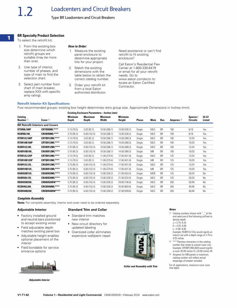
V1-T1-62 Volume 1—Residential and Light Commercial CA08100002E—February 2018 www.eaton.com
1
1
1
1
1
1
1
1
1
1
1
1
1
1
1
1
1
1
1
1
1
1
1
1
1
1
1
1
1
1
1.2 Loadcenters and Circuit Breakers
Type BR Loadcenters and Circuit Breakers
BR Specialty Product SelectionTo select the retrofit kit:
1. From the existing box size determine which retrofit groups are suitable (may be more than one).
2. Use type of interior, number of phases, and type of main to find the selection chart.
3. Select part number from chart (if main breaker, replace XXX with specific amp rating).
How to Order:1. Measure the existing
panel enclosure to determine appropriate kits for your project.
2. Match the existing dimensions with the table below to obtain the correct catalog number.
3. Order your retrofit kit from a local Eaton authorized distributor.
Need assistance or can’t find retrofit to fit existing enclosure?
Call Eaton’s Residential Flex Center at 1-800-330-6479 or email for all your retrofit needs. Go to www.eaton.com/eccn to locate an Eaton Certified Contractor.
Retrofit Interior Kit Specifications
Five recommended groups: existing box height determines retro group size. Approximate Dimensions in Inches (mm).
Complete AssemblyNote: For complete assembly, interior and cover need to be ordered separately.
Adjustable Interior
● Factory installed ground and neutral bars positioned to accept existing wires
● Field adjustable depth matches existing panel box
● Adjustable height enables optional placement of the interior
● Field bondable for service entrance options
Adjustable Interior
Standard Trim and Collar
● Standard trim matches new interior
● New circuit directory for updated labeling
● Oversized collar eliminates expensive wall/paint repair
Collar and Assembly with Trim
Notes1 Catalog numbers shown with “_” at the
end need one of the following suffixes to denote depth:J = 3.75–4.25K = 4.25–5.00L = 5.00–6.00Example: RUBR12L125J would signify an interior set with a depth range of 3.75 to 4.25 inches.
2 ****Denotes characters in the catalog number that relate to overall cover size.Example: CRTBR12ML2620 would signify a cover 26.00 inches H x 20.00 inches W.
3 Amperes for MB panels is maximum; catalog number will reflect actual amperage of breaker included.
For UL applications, maximum cover sizes may apply.
Existing Enclosure Parameters—Inches (mm)Catalog Number 1 Cover 2
MinimumDepth
MaximumDepth
MinimumWidth
MinimumHeight Phase Main Bus Amperes 3
Spaces / Circuits
UL 67 Listed
BR Retrofit Interiors and Covers
RTBR8L100P CRTBR8ML**** 3.13 (79.5) 3.63 (92.2) 10.50 (266.7) 13.00 (330.2) Single MLO BR 100 8/16 Yes
RUBR8L100_ CRUBR8ML**** 3.75 (95.3) 6.00 (152.4) 10.50 (266.7) 13.00 (330.2) Single MLO BR 100 8/16 Yes
RTBR12L100P CRTBR12ML**** 3.13 (79.5) 3.63 (92.2) 10.50 (266.7) 14.50 (368.3) Single MLO BR 100 12/24 Yes
RTBR10B100P CRTBR12ML**** 3.13 (79.5) 3.63 (92.2) 10.50 (266.7) 14.50 (368.3) Single MLO BR 100 10/20 Yes
RUBR12L100_ CRUBR12ML**** 3.75 (95.3) 6.00 (152.4) 10.50 (266.7) 14.50 (368.3) Single MLO BR 100 12/24 Yes
RUBR10B100_ CRUBR12ML**** 3.75 (95.3) 6.00 (152.4) 10.50 (266.7) 14.50 (368.3) Single MB BR 100 10/20 Yes
RTBR12L125P CRTBR12ML**** 3.13 (79.5) 3.63 (92.2) 11.00 (279.4) 17.00 (431.8) Single MLO BR 125 12/24 Yes
RTBR10B125P CRTBR12ML**** 3.13 (79.5) 3.63 (92.2) 11.00 (279.4) 17.00 (431.8) Single MB BR 125 10/20 Yes
RUBR12L125_ CRUBR12ML**** 3.75 (95.3) 6.00 (152.4) 11.00 (279.4) 17.00 (431.8) Single MLO BR 125 12/24 Yes
RUBR10B125_ CRUBR12ML**** 3.75 (95.3) 6.00 (152.4) 11.00 (279.4) 17.00 (431.8) Single MB BR 125 10/20 Yes
RABR20B125_ CRABR20ML**** 3.75 (95.3) 6.00 (152.4) 13.00 (330.2) 21.00 (533.4) Single MCB BR 125 20/24 No
RABR20L125_ CRABR20ML**** 3.75 (95.3) 6.00 (152.4) 13.00 (330.2) 21.00 (533.4) Single MLO BR 125 20/24 No
RBBR20B200_ CRBBR20BW**** 3.75 (95.3) 6.00 (152.4) 13.00 (330.2) 29.00 (736.6) Single MLO BR 200 20/40 No
RCBR40L200_ CRCBR40ML**** 3.75 (95.3) 6.00 (152.4) 13.00 (330.2) 34.00 (863.6) Single MLO BR 200 30/40 No
RDBR40B200_ CRDBR40BW**** 3.75 (95.3) 6.00 (152.4) 13.00 (330.2) 37.00 (939.8) Single MLO BR 200 40/40 No
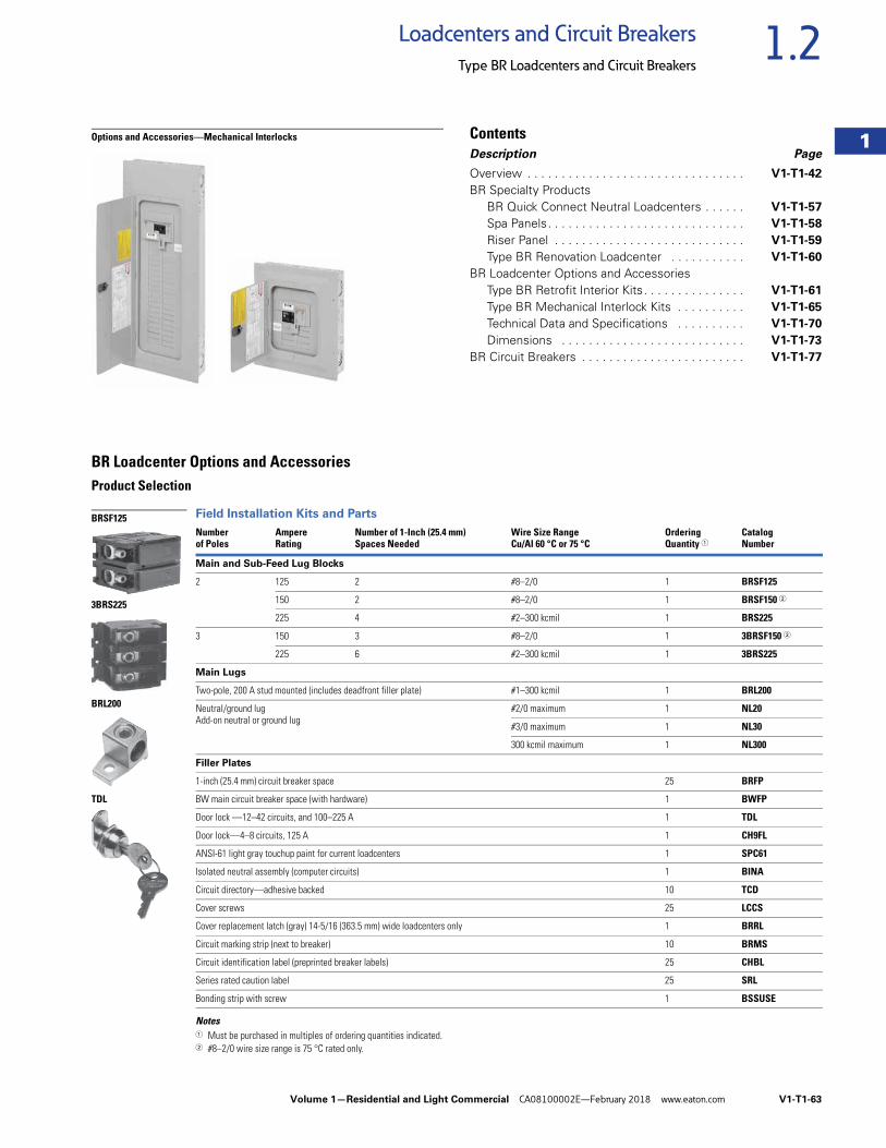
Volume 1—Residential and Light Commercial CA08100002E—February 2018 www.eaton.com V1-T1-63
1
1
1
1
1
1
1
1
1
1
1
1
1
1
1
1
1
1
1
1
1
1
1
1
1
1
1
1
1
1
1.2Loadcenters and Circuit Breakers
Type BR Loadcenters and Circuit Breakers
Options and Accessories—Mechanical Interlocks ContentsDescription Page
Overview . . . . . . . . . . . . . . . . . . . . . . . . . . . . . . . . V1-T1-42
BR Specialty ProductsBR Quick Connect Neutral Loadcenters . . . . . . V1-T1-57
Spa Panels. . . . . . . . . . . . . . . . . . . . . . . . . . . . . V1-T1-58
Riser Panel . . . . . . . . . . . . . . . . . . . . . . . . . . . . V1-T1-59
Type BR Renovation Loadcenter . . . . . . . . . . . V1-T1-60
BR Loadcenter Options and AccessoriesType BR Retrofit Interior Kits. . . . . . . . . . . . . . . V1-T1-61
Type BR Mechanical Interlock Kits . . . . . . . . . . V1-T1-65
Technical Data and Specifications . . . . . . . . . . V1-T1-70
Dimensions . . . . . . . . . . . . . . . . . . . . . . . . . . . V1-T1-73
BR Circuit Breakers . . . . . . . . . . . . . . . . . . . . . . . . V1-T1-77
BR Loadcenter Options and AccessoriesProduct Selection
Field Installation Kits and Parts
Notes1 Must be purchased in multiples of ordering quantities indicated.2 #8–2/0 wire size range is 75 °C rated only.
Number of Poles
AmpereRating
Number of 1-Inch (25.4 mm)Spaces Needed
Wire Size RangeCu/Al 60 °C or 75 °C
OrderingQuantity 1
CatalogNumber
Main and Sub-Feed Lug Blocks
2 125 2 #8–2/0 1 BRSF125
150 2 #8–2/0 1 BRSF150 2
225 4 #2–300 kcmil 1 BRS225
3 150 3 #8–2/0 1 3BRSF150 2
225 6 #2–300 kcmil 1 3BRS225
Main Lugs
Two-pole, 200 A stud mounted (includes deadfront filler plate) #1–300 kcmil 1 BRL200
Neutral/ground lugAdd-on neutral or ground lug
#2/0 maximum 1 NL20
#3/0 maximum 1 NL30
300 kcmil maximum 1 NL300
Filler Plates
1-inch (25.4 mm) circuit breaker space 25 BRFP
BW main circuit breaker space (with hardware) 1 BWFP
Door lock —12–42 circuits, and 100–225 A 1 TDL
Door lock—4–8 circuits, 125 A 1 CH9FL
ANSI-61 light gray touchup paint for current loadcenters 1 SPC61
Isolated neutral assembly (computer circuits) 1 BINA
Circuit directory—adhesive backed 10 TCD
Cover screws 25 LCCS
Cover replacement latch (gray) 14-5/16 (363.5 mm) wide loadcenters only 1 BRRL
Circuit marking strip (next to breaker) 10 BRMS
Circuit identification label (preprinted breaker labels) 25 CHBL
Series rated caution label 25 SRL
Bonding strip with screw 1 BSSUSE
BRSF125
3BRS225
BRL200
TDL
V1-T1-64 Volume 1—Residential and Light Commercial CA08100002E—February 2018 www.eaton.com
1
1
1
1
1
1
1
1
1
1
1
1
1
1
1
1
1
1
1
1
1
1
1
1
1
1
1
1
1
1
1.2 Loadcenters and Circuit Breakers
Type BR Loadcenters and Circuit Breakers
Three-Phase Accessories
Three-Phase Main Breaker Kits—10 kAIC
Three-Phase Main Lugs Kit for Convertible Loadcenters
Note1 For subfeed.
Box sizes Pages V1-T1-73 through V1-T1-76.
AmpereRating
Wire Size RangeCu/Al 60 °C or 75 °C
CatalogNumber
100 #6–4/0 CC3100N
125 #6–4/0 CC3125N
150 #6–4/0 CC3150N
175 #2/0–300 kcmil CC3175N
200 #2/0–300 kcmil CC3200N
225 #2/0–300 kcmil CC3225N
AmpereRating
Wire Size RangeCu/Al 60 °C or 75 °C
CatalogNumber
225 #1–300 kcmil 3BRL225
225 #1–300 kcmil 3BRS225 1
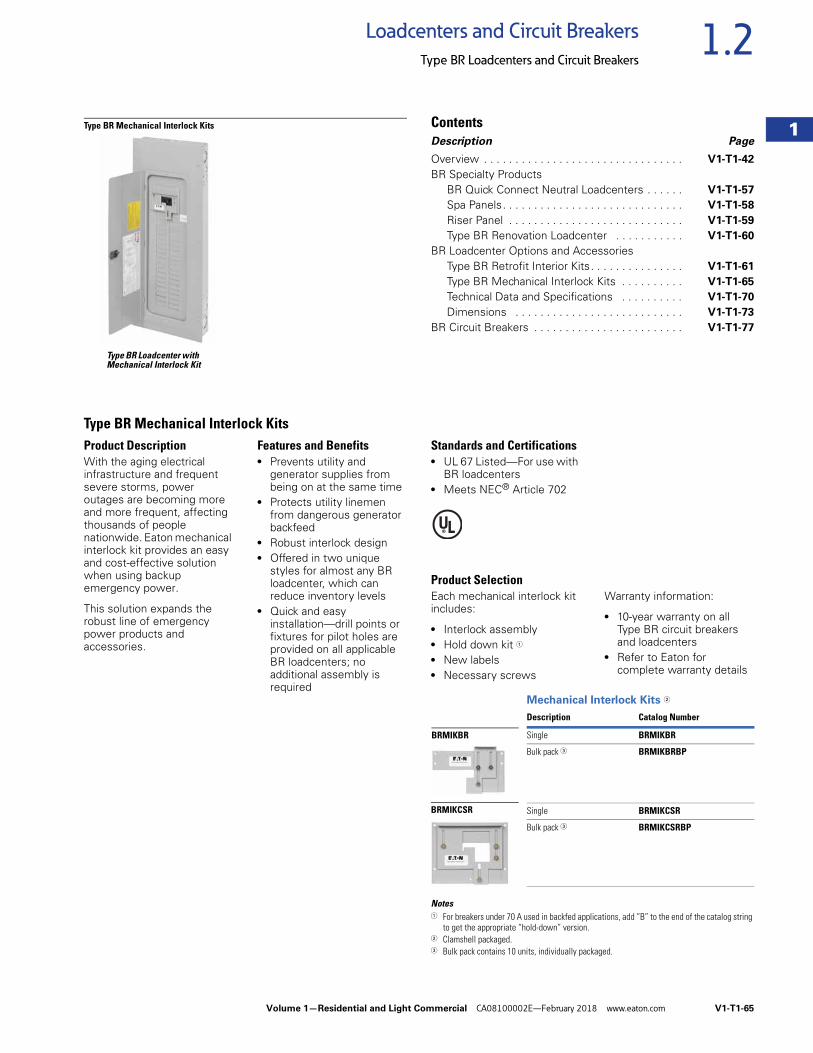
Volume 1—Residential and Light Commercial CA08100002E—February 2018 www.eaton.com V1-T1-65
1
1
1
1
1
1
1
1
1
1
1
1
1
1
1
1
1
1
1
1
1
1
1
1
1
1
1
1
1
1
1.2Loadcenters and Circuit Breakers
Type BR Loadcenters and Circuit Breakers
Type BR Loadcenter with Mechanical Interlock Kit
Type BR Mechanical Interlock Kits ContentsDescription Page
Overview . . . . . . . . . . . . . . . . . . . . . . . . . . . . . . . . V1-T1-42
BR Specialty ProductsBR Quick Connect Neutral Loadcenters . . . . . . V1-T1-57
Spa Panels. . . . . . . . . . . . . . . . . . . . . . . . . . . . . V1-T1-58
Riser Panel . . . . . . . . . . . . . . . . . . . . . . . . . . . . V1-T1-59
Type BR Renovation Loadcenter . . . . . . . . . . . V1-T1-60
BR Loadcenter Options and AccessoriesType BR Retrofit Interior Kits. . . . . . . . . . . . . . . V1-T1-61
Type BR Mechanical Interlock Kits . . . . . . . . . . V1-T1-65
Technical Data and Specifications . . . . . . . . . . V1-T1-70
Dimensions . . . . . . . . . . . . . . . . . . . . . . . . . . . V1-T1-73
BR Circuit Breakers . . . . . . . . . . . . . . . . . . . . . . . . V1-T1-77
Type BR Mechanical Interlock KitsProduct DescriptionWith the aging electrical infrastructure and frequent severe storms, power outages are becoming more and more frequent, affecting thousands of people nationwide. Eaton mechanical interlock kit provides an easy and cost-effective solution when using backup emergency power.
This solution expands the robust line of emergency power products and accessories.
Features and Benefits● Prevents utility and
generator supplies from being on at the same time
● Protects utility linemen from dangerous generator backfeed
● Robust interlock design● Offered in two unique
styles for almost any BR loadcenter, which can reduce inventory levels
● Quick and easy installation—drill points or fixtures for pilot holes are provided on all applicable BR loadcenters; no additional assembly is required
Standards and Certifications● UL 67 Listed—For use with
BR loadcenters● Meets NEC® Article 702
Product SelectionEach mechanical interlock kit includes:
● Interlock assembly● Hold down kit 1
● New labels● Necessary screws
Warranty information:
● 10-year warranty on all Type BR circuit breakers and loadcenters
● Refer to Eaton for complete warranty details
Mechanical Interlock Kits 2
Notes1 For breakers under 70 A used in backfed applications, add “B” to the end of the catalog string
to get the appropriate “hold-down” version.2 Clamshell packaged.3 Bulk pack contains 10 units, individually packaged.
Description Catalog Number
Single BRMIKBR
Bulk pack 3 BRMIKBRBP
Single BRMIKCSR
Bulk pack 3 BRMIKCSRBP
BRMIKCSR
BRMIKBR
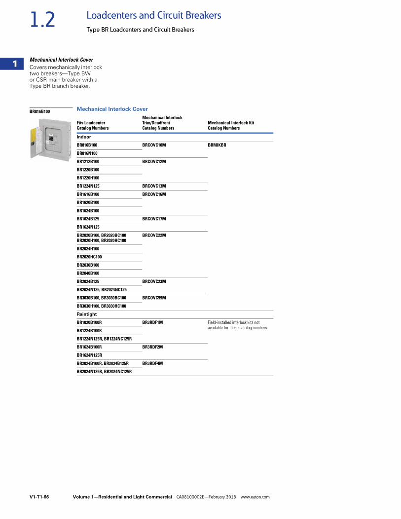
V1-T1-66 Volume 1—Residential and Light Commercial CA08100002E—February 2018 www.eaton.com
1
1
1
1
1
1
1
1
1
1
1
1
1
1
1
1
1
1
1
1
1
1
1
1
1
1
1
1
1
1
1.2 Loadcenters and Circuit Breakers
Type BR Loadcenters and Circuit Breakers
Mechanical Interlock CoverCovers mechanically interlock two breakers—Type BW or CSR main breaker with a Type BR branch breaker.
Mechanical Interlock Cover
Fits LoadcenterCatalog Numbers
Mechanical Interlock Trim/Deadfront Catalog Numbers
Mechanical Interlock KitCatalog Numbers
Indoor
BR816B100 BRCOVC10M BRMIKBR
BR816N100
BR1212B100 BRCOVC12M
BR1220B100
BR1220H100
BR1224N125 BRCOVC13M
BR1616B100 BRCOVC16M
BR1620B100
BR1624B100
BR1624B125 BRCOVC17M
BR1624N125
BR2020B100, BR2020BC100 BR2020H100, BR2020HC100
BRCOVC22M
BR2024H100
BR2020HC100
BR2030B100
BR2040B100
BR2024B125 BRCOVC23M
BR2024N125, BR2024NC125
BR3030B100, BR3030BC100 BRCOVC59M
BR3030H100, BR3030HC100
Raintight
BR1020B100R BR3RDF1M Field-installed interlock kits not available for these catalog numbers.
BR1224B100R
BR1224N125R, BR1224NC125R
BR1624B100R BR3RDF2M
BR1624N125R
BR2024B100R, BR2024B125R BR3RDF4M
BR2024N125R, BR2024NC125R
BR816B100
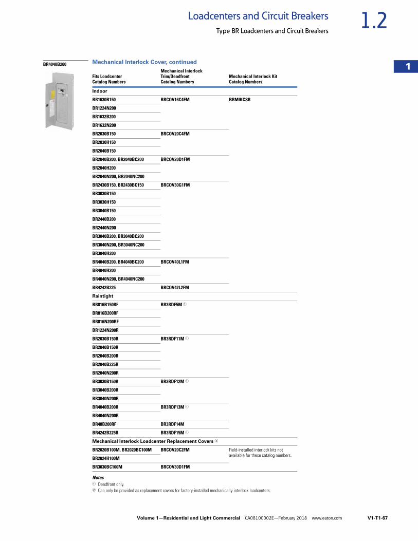
Volume 1—Residential and Light Commercial CA08100002E—February 2018 www.eaton.com V1-T1-67
1
1
1
1
1
1
1
1
1
1
1
1
1
1
1
1
1
1
1
1
1
1
1
1
1
1
1
1
1
1
1.2Loadcenters and Circuit Breakers
Type BR Loadcenters and Circuit Breakers
Mechanical Interlock Cover, continued
Notes1 Deadfront only.2 Can only be provided as replacement covers for factory-installed mechanically interlock loadcenters.
Fits LoadcenterCatalog Numbers
Mechanical Interlock Trim/Deadfront Catalog Numbers
Mechanical Interlock KitCatalog Numbers
Indoor
BR1630B150 BRCOV16C4FM BRMIKCSR
BR1224N200
BR1632B200
BR1632N200
BR2030B150 BRCOV20C4FM
BR2030H150
BR2040B150
BR2040B200, BR2040BC200 BRCOV20D1FM
BR2040H200
BR2040N200, BR2040NC200
BR2430B150, BR2430BC150 BRCOV30G1FM
BR3030B150
BR3030H150
BR3040B150
BR2440B200
BR2440N200
BR3040B200, BR3040BC200
BR3040N200, BR3040NC200
BR3040H200
BR4040B200, BR4040BC200 BRCOV40L1FM
BR4040H200
BR4040N200, BR4040NC200
BR4242B225 BRCOV42L2FM
Raintight
BR816B150RF BR3RDF5M 1
BR816B200RF
BR816N200RF
BR1224N200R
BR2030B150R BR3RDF11M 1
BR2040B150R
BR2040B200R
BR2040B225R
BR2040N200R
BR3030B150R BR3RDF12M 1
BR3040B200R
BR3040N200R
BR4040B200R BR3RDF13M 1
BR4040N200R
BR48B200RF BR3RDF14M
BR4242B225R BR3RDF15M 1
Mechanical Interlock Loadcenter Replacement Covers 2
BR2020B100M, BR2020BC100M BRCOV20C2FM Field-installed interlock kits not available for these catalog numbers.
BR2024H100M
BR3030BC100M BRCOV30D1FM
BR4040B200
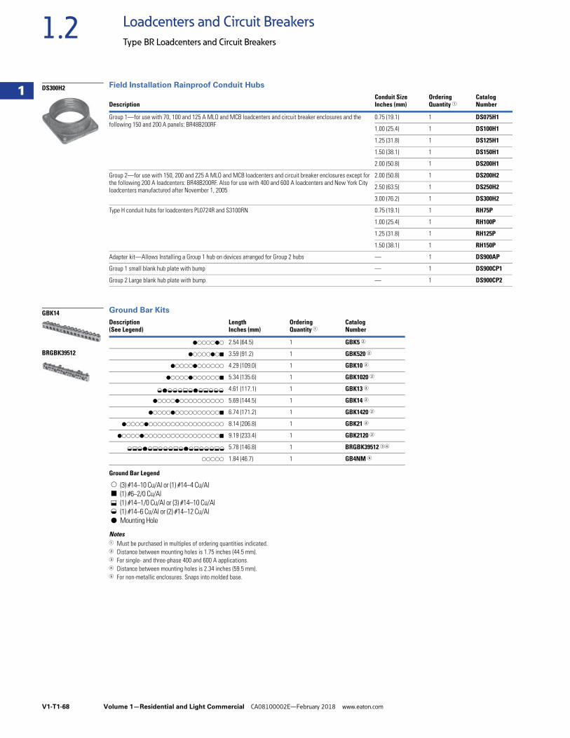
V1-T1-68 Volume 1—Residential and Light Commercial CA08100002E—February 2018 www.eaton.com
1
1
1
1
1
1
1
1
1
1
1
1
1
1
1
1
1
1
1
1
1
1
1
1
1
1
1
1
1
1
1.2 Loadcenters and Circuit Breakers
Type BR Loadcenters and Circuit Breakers
Field Installation Rainproof Conduit Hubs
Ground Bar Kits
Ground Bar Legend
Notes1 Must be purchased in multiples of ordering quantities indicated.2 Distance between mounting holes is 1.75 inches (44.5 mm).3 For single- and three-phase 400 and 600 A applications.4 Distance between mounting holes is 2.34 inches (59.5 mm).5 For non-metallic enclosures. Snaps into molded base.
DescriptionConduit SizeInches (mm)
OrderingQuantity 1
CatalogNumber
Group 1—for use with 70, 100 and 125 A MLO and MCB loadcenters and circuit breaker enclosures and the following 150 and 200 A panels: BR48B200RF
0.75 (19.1) 1 DS075H1
1.00 (25.4) 1 DS100H1
1.25 (31.8) 1 DS125H1
1.50 (38.1) 1 DS150H1
2.00 (50.8) 1 DS200H1
Group 2—for use with 150, 200 and 225 A MLO and MCB loadcenters and circuit breaker enclosures except for the following 200 A loadcenters: BR48B200RF. Also for use with 400 and 600 A loadcenters and New York City loadcenters manufactured after November 1, 2005
2.00 (50.8) 1 DS200H2
2.50 (63.5) 1 DS250H2
3.00 (76.2) 1 DS300H2
Type H conduit hubs for loadcenters PL0724R and S3100RN 0.75 (19.1) 1 RH75P
1.00 (25.4) 1 RH100P
1.25 (31.8) 1 RH125P
1.50 (38.1) 1 RH150P
Adapter kit—Allows Installing a Group 1 hub on devices arranged for Group 2 hubs — 1 DS900AP
Group 1 small blank hub plate with bump — 1 DS900CP1
Group 2 Large blank hub plate with bump — 1 DS900CP2
Description(See Legend)
LengthInches (mm)
OrderingQuantity 1
CatalogNumber
dssssds 2.54 (64.5) 1 GBK5 2
dssssdsj 3.59 (91.2) 1 GBK520 2
dssssdssssss 4.29 (109.0) 1 GBK10 2
dssssdssssssj 5.34 (135.6) 1 GBK1020 2
4.61 (117.1) 1 GBK13 2
dssssdssssssssss 5.69 (144.5) 1 GBK14 2
dssssdssssssssssj 6.74 (171.2) 1 GBK1420 2
dssssdsssssssssssssssss 8.14 (206.8) 1 GBK21 2
dssssdsssssssssssssssssj 9.19 (233.4) 1 GBK2120 2
5.78 (146.8) 1 BRGBK39512 34
sssss 1.84 (46.7) 1 GB4NM 5
s
j
d
(3) #14–10 Cu/Al or (1) #14–4 Cu/Al(1) #6–2/0 Cu/Al(1) #14–1/0 Cu/Al or (3) #14–10 Cu/Al(1) #14–6 Cu/Al or (2) #14–12 Cu/AlMounting Hole
DS300H2
GBK14
BRGBK39512
f d f f f k f d f k f f f
f k f d f k f f f k f d f k f f f k f
kf
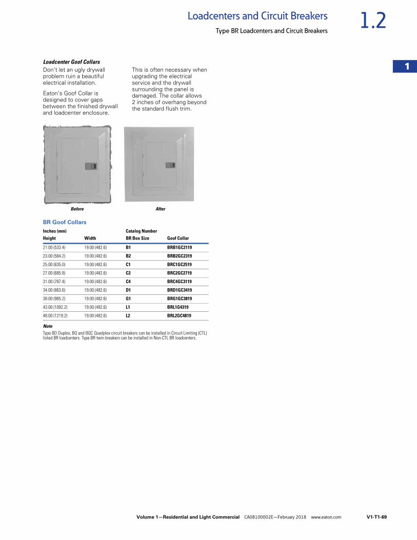
Volume 1—Residential and Light Commercial CA08100002E—February 2018 www.eaton.com V1-T1-69
1
1
1
1
1
1
1
1
1
1
1
1
1
1
1
1
1
1
1
1
1
1
1
1
1
1
1
1
1
1
1.2Loadcenters and Circuit Breakers
Type BR Loadcenters and Circuit Breakers
Loadcenter Goof CollarsDon’t let an ugly drywall problem ruin a beautiful electrical installation.
Eaton’s Goof Collar is designed to cover gaps between the finished drywall and loadcenter enclosure.
This is often necessary when upgrading the electrical service and the drywall surrounding the panel is damaged. The collar allows 2 inches of overhang beyond the standard flush trim.
Before After
BR Goof Collars
NoteType BD Duplex, BQ and BQC Quadplex circuit breakers can be installed in Circuit Limiting (CTL) listed BR loadcenters. Type BR twin breakers can be installed in Non-CTL BR loadcenters.
Inches (mm) Catalog NumberHeight Width BR Box Size Goof Collar
21.00 (533.4) 19.00 (482.6) B1 BRB1GC2119
23.00 (584.2) 19.00 (482.6) B2 BRB2GC2319
25.00 (635.0) 19.00 (482.6) C1 BRC1GC2519
27.00 (685.8) 19.00 (482.6) C2 BRC2GC2719
31.00 (787.4) 19.00 (482.6) C4 BRC4GC3119
34.00 (863.6) 19.00 (482.6) D1 BRD1GC3419
38.00 (965.2) 19.00 (482.6) G1 BRG1GC3819
43.00 (1092.2) 19.00 (482.6) L1 BRL1G4319
48.00 (1219.2) 19.00 (482.6) L2 BRL2GC4819
SCOTTHAS
PHOTO
V1-T1-70 Volume 1—Residential and Light Commercial CA08100002E—February 2018 www.eaton.com
1
1
1
1
1
1
1
1
1
1
1
1
1
1
1
1
1
1
1
1
1
1
1
1
1
1
1
1
1
1
1.2 Loadcenters and Circuit Breakers
Type BR Loadcenters and Circuit Breakers
Technical Data and Specifications
GeneralA. The Contractor shall
furnish and install deadfront loadcenters incorporating circuit breakers of the number, rating and type as specified herein and as shown on the contract drawings.
B. The loadcenter and all components shall be designed, manufactured and tested in accordance with the latest applicable standards of UL, NEMA and NEC including:
1. UL 67—Standards for Panelboards.
C. UL 50—Standards for Cabinets and Boxes.
D. UL 489—Standards for Molded Case Circuit Breakers.
E. UL 869—Standards for Service Equipment.
F. Federal Specification W-C 375B—Circuit Breakers.
G. Federal Specification W-C P115b—Panel Power Distribution Type 1, Class 2.
QualificationsA. The manufacturer of the
loadcenter shall be the manufacturer of the circuit breaker within the loadcenter.
B. For the equipment specified herein, the manufacturer shall be ISO 9000 certified.
C. The manufacturer of this equipment shall have produced similar electrical equipment for a minimum period of seven (7) years.
ManufacturersA. Eaton.
RatingsA. Loadcenters shall be
rated for 120/240 Vac and shall have short-circuit ratings as shown on the drawings or as herein scheduled, but not less than 10,000 amperes rms symmetrical.
B. Circuit breakers shall be a minimum of 125 A frame. Circuit breakers 15 through 125 A trip size shall take up the same pole spacing.
C. Loadcenters shall be labeled with a UL short-circuit rating. When series combination ratings are applied with integral or remote upstream devices, a label shall be provided. Series combination ratings shall cover all trip ratings of installed frames. It shall state the conditions of the UL series ratings including:
1. Size and type of upstream device.
2. Branch devices that can be used.
3. UL series short circuit rating.
ConstructionA. All interiors, with the
exception of the branch circuit breakers, shall be completely factory assembled with main breakers, main lugs, or no main device.
B. Interiors shall be designed so that circuit breakers can be replaced without disturbing adjacent units and without removing the main bus connectors and shall be designed so that circuits may be changed without machining, drilling, or tapping.
C. Physical means shall be provided to prevent the installation of more overcurrent devices than that number for which the enclosure was designed, rated and approved. Half-size breakers shall have a UL listed rejection tab over the line terminals. Loadcenter interiors must have notched stabs to accept these rejection tab class CTL breakers, if required and approved.
BusA. Busbars for the main and
cross connectors shall be [tin-plated aluminum] [copper] in accordance with Underwriters Laboratories standards. Busing shall be braced throughout to conform to industry standard practice governing short-circuit stresses in loadcenters.
Note: Note to spec writer—select one (copper available in limited ratings).
B. Neutral busing shall have a suitable lug for each outgoing feeder requiring a neutral connection of same ampacity as branch.
Wiring/TerminationA. All wire connectors and
terminals shall be of the anti-turn solderless type and shall be suitable for copper or aluminum wire of the sizes indicated. All connectors must meet the “Requirements for Wire Connectors and Soldering Lugs” as stated in UL 486B.
B. All loadcenters where marked shall be suitable for use with 60 °C or 75 °C rated wire.
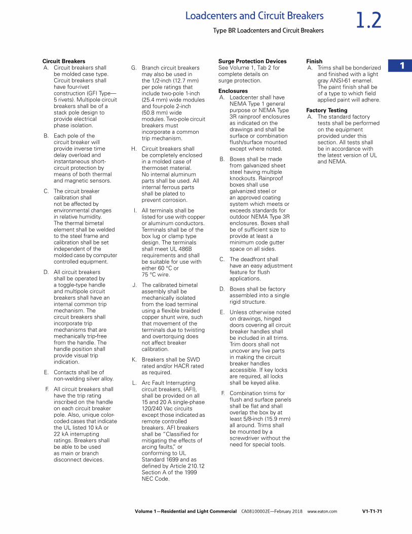
Volume 1—Residential and Light Commercial CA08100002E—February 2018 www.eaton.com V1-T1-71
1
1
1
1
1
1
1
1
1
1
1
1
1
1
1
1
1
1
1
1
1
1
1
1
1
1
1
1
1
1
1.2Loadcenters and Circuit Breakers
Type BR Loadcenters and Circuit Breakers
Circuit BreakersA. Circuit breakers shall
be molded case type. Circuit breakers shall have four-rivet construction (GFI Type—5 rivets). Multipole circuit breakers shall be of a stack pole design to provide electrical phase isolation.
B. Each pole of the circuit breaker will provide inverse time delay overload and instantaneous short-circuit protection by means of both thermal and magnetic sensors.
C. The circuit breaker calibration shall not be affected by environmental changes in relative humidity. The thermal bimetal element shall be welded to the steel frame and calibration shall be set independent of the molded case by computer controlled equipment.
D. All circuit breakers shall be operated by a toggle-type handle and multipole circuit breakers shall have an internal common trip mechanism. The circuit breakers shall incorporate trip mechanisms that are mechanically trip-free from the handle. The handle position shall provide visual trip indication.
E. Contacts shall be of non-welding silver alloy.
F. All circuit breakers shall have the trip rating inscribed on the handle on each circuit breaker pole. Also, unique color-coded cases that indicate the UL listed 10 kA or 22 kA interrupting ratings. Breakers shall be able to be used as main or branch disconnect devices.
G. Branch circuit breakers may also be used in the 1/2-inch (12.7 mm) per pole ratings that include two-pole 1-inch (25.4 mm) wide modules and four-pole 2-inch (50.8 mm) wide modules. Two-pole circuit breakers must incorporate a common trip mechanism.
H. Circuit breakers shall be completely enclosed in a molded case of thermoset material. No internal aluminum parts shall be used. All internal ferrous parts shall be plated to prevent corrosion.
I. All terminals shall be listed for use with copper or aluminum conductors. Terminals shall be of the box lug or clamp type design. The terminals shall meet UL 486B requirements and shall be suitable for use with either 60 °C or 75 °C wire.
J. The calibrated bimetal assembly shall be mechanically isolated from the load terminal using a flexible braided copper shunt wire, such that movement of the terminals due to twisting and overtorquing does not affect breaker calibration.
K. Breakers shall be SWD rated and/or HACR rated as required.
L. Arc Fault Interrupting circuit breakers, (AFI), shall be provided on all 15 and 20 A single-phase 120/240 Vac circuits except those indicated as remote controlled breakers. AFI breakers shall be “Classified for mitigating the effects of arcing faults,” or conforming to UL Standard 1699 and as defined by Article 210.12 Section A of the 1999 NEC Code.
Surge Protection DevicesSee Volume 1, Tab 2 for complete details on surge protection.
EnclosuresA. Loadcenter shall have
NEMA Type 1 general purpose or NEMA Type 3R rainproof enclosures as indicated on the drawings and shall be surface or combination flush/surface mounted except where noted.
B. Boxes shall be made from galvanized sheet steel having multiple knockouts. Rainproof boxes shall use galvanized steel or an approved coating system which meets or exceeds standards for outdoor NEMA Type 3R enclosures. Boxes shall be of sufficient size to provide at least a minimum code gutter space on all sides.
C. The deadfront shall have an easy adjustment feature for flush applications.
D. Boxes shall be factory assembled into a single rigid structure.
E. Unless otherwise noted on drawings, hinged doors covering all circuit breaker handles shall be included in all trims. Trim doors shall not uncover any live parts in making the circuit breaker handles accessible. If key locks are required, all locks shall be keyed alike.
F. Combination trims for flush and surface panels shall be flat and shall overlap the box by at least 5/8-inch (15.9 mm) all around. Trims shall be mounted by a screwdriver without the need for special tools.
FinishA. Trims shall be bonderized
and finished with a light gray ANSI-61 enamel. The paint finish shall be of a type to which field applied paint will adhere.
Factory TestingA. The standard factory
tests shall be performed on the equipment provided under this section. All tests shall be in accordance with the latest version of UL and NEMA.
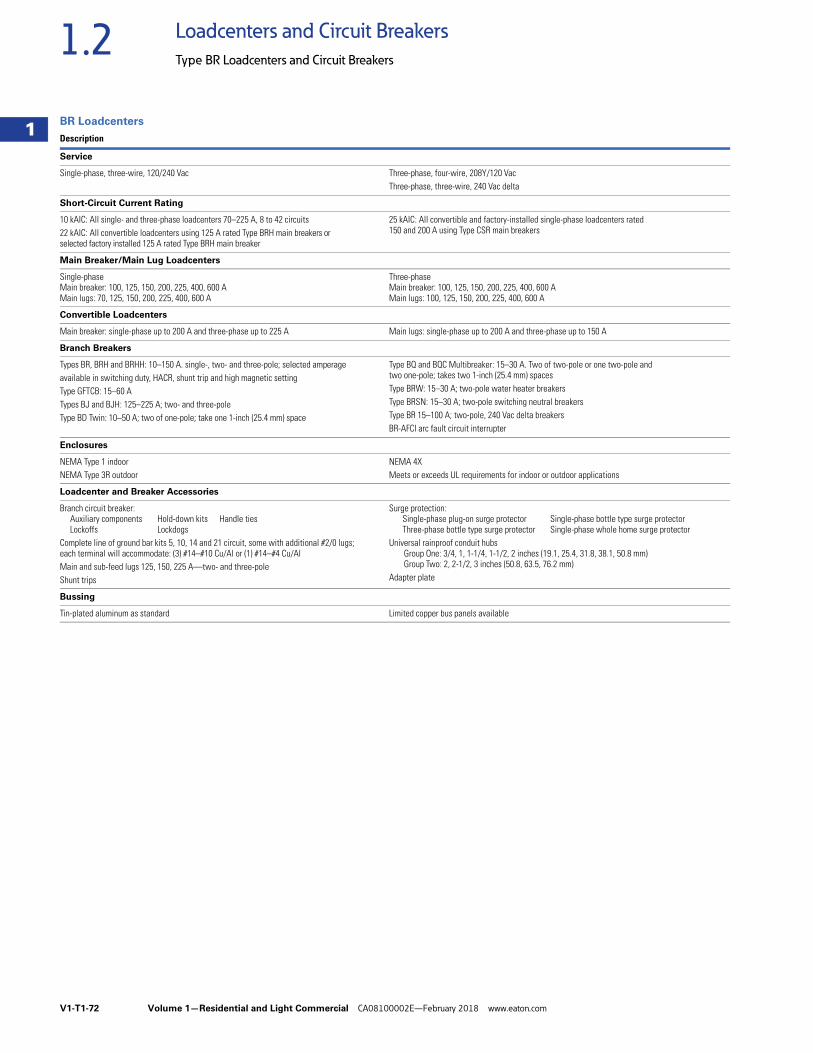
V1-T1-72 Volume 1—Residential and Light Commercial CA08100002E—February 2018 www.eaton.com
1
1
1
1
1
1
1
1
1
1
1
1
1
1
1
1
1
1
1
1
1
1
1
1
1
1
1
1
1
1
1.2 Loadcenters and Circuit Breakers
Type BR Loadcenters and Circuit Breakers
BR Loadcenters
Description
Service
Single-phase, three-wire, 120/240 Vac Three-phase, four-wire, 208Y/120 VacThree-phase, three-wire, 240 Vac delta
Short-Circuit Current Rating
10 kAIC: All single- and three-phase loadcenters 70–225 A, 8 to 42 circuits22 kAIC: All convertible loadcenters using 125 A rated Type BRH main breakers or selected factory installed 125 A rated Type BRH main breaker
25 kAIC: All convertible and factory-installed single-phase loadcenters rated 150 and 200 A using Type CSR main breakers
Main Breaker/Main Lug Loadcenters
Single-phaseMain breaker: 100, 125, 150, 200, 225, 400, 600 AMain lugs: 70, 125, 150, 200, 225, 400, 600 A
Three-phaseMain breaker: 100, 125, 150, 200, 225, 400, 600 AMain lugs: 100, 125, 150, 200, 225, 400, 600 A
Convertible Loadcenters
Main breaker: single-phase up to 200 A and three-phase up to 225 A Main lugs: single-phase up to 200 A and three-phase up to 150 A
Branch Breakers
Types BR, BRH and BRHH: 10–150 A. single-, two- and three-pole; selected amperage available in switching duty, HACR, shunt trip and high magnetic settingType GFTCB: 15–60 ATypes BJ and BJH: 125–225 A; two- and three-poleType BD Twin: 10–50 A; two of one-pole; take one 1-inch (25.4 mm) space
Type BQ and BQC Multibreaker: 15–30 A. Two of two-pole or one two-pole and two one-pole; takes two 1-inch (25.4 mm) spacesType BRW: 15–30 A; two-pole water heater breakersType BRSN: 15–30 A; two-pole switching neutral breakersType BR 15–100 A; two-pole, 240 Vac delta breakersBR-AFCI arc fault circuit interrupter
Enclosures
NEMA Type 1 indoorNEMA Type 3R outdoor
NEMA 4XMeets or exceeds UL requirements for indoor or outdoor applications
Loadcenter and Breaker Accessories
Branch circuit breaker: Auxiliary components Hold-down kits Handle tiesLockoffs Lockdogs
Complete line of ground bar kits 5, 10, 14 and 21 circuit, some with additional #2/0 lugs; each terminal will accommodate: (3) #14–#10 Cu/Al or (1) #14–#4 Cu/AlMain and sub-feed lugs 125, 150, 225 A—two- and three-poleShunt trips
Surge protection: Single-phase plug-on surge protector Single-phase bottle type surge protectorThree-phase bottle type surge protector Single-phase whole home surge protector
Universal rainproof conduit hubsGroup One: 3/4, 1, 1-1/4, 1-1/2, 2 inches (19.1, 25.4, 31.8, 38.1, 50.8 mm)Group Two: 2, 2-1/2, 3 inches (50.8, 63.5, 76.2 mm)
Adapter plate
Bussing
Tin-plated aluminum as standard Limited copper bus panels available
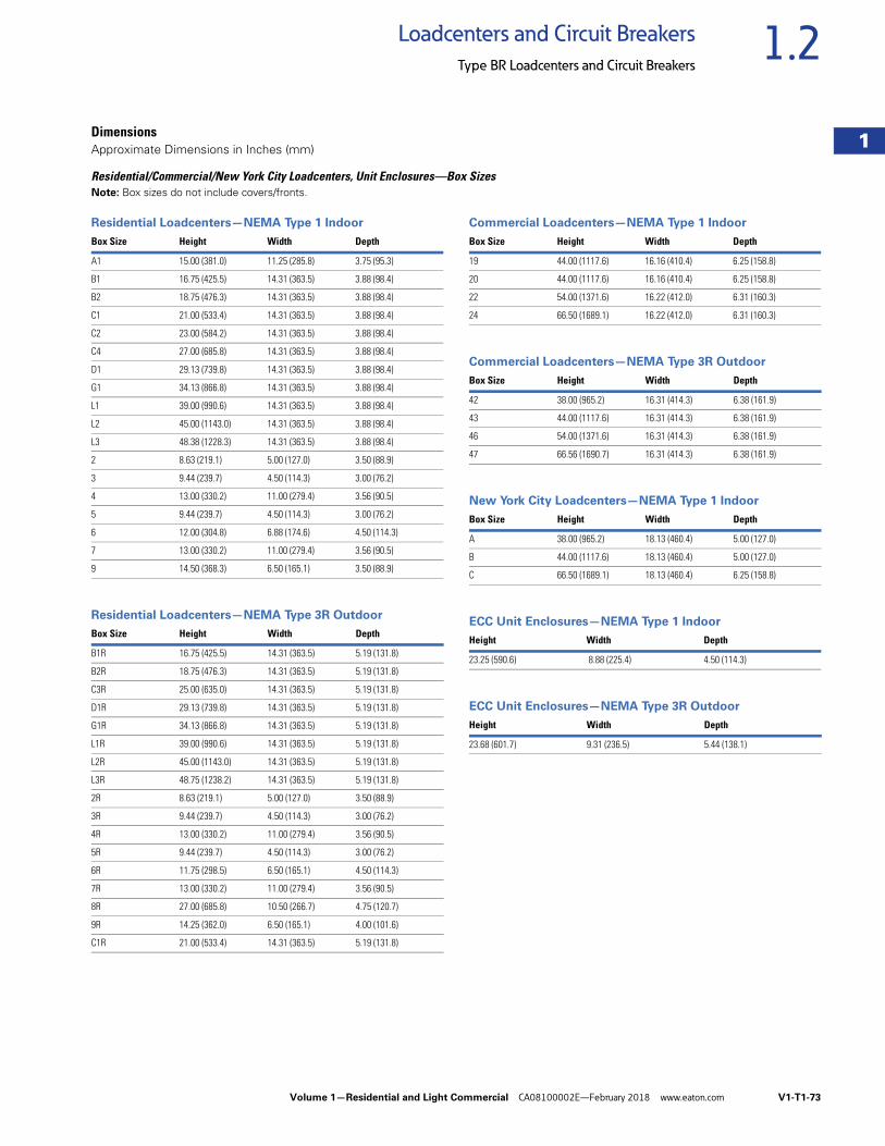
Volume 1—Residential and Light Commercial CA08100002E—February 2018 www.eaton.com V1-T1-73
1
1
1
1
1
1
1
1
1
1
1
1
1
1
1
1
1
1
1
1
1
1
1
1
1
1
1
1
1
1
1.2Loadcenters and Circuit Breakers
Type BR Loadcenters and Circuit Breakers
DimensionsApproximate Dimensions in Inches (mm)
Residential/Commercial/New York City Loadcenters, Unit Enclosures—Box SizesNote: Box sizes do not include covers/fronts.
Residential Loadcenters—NEMA Type 1 Indoor
Residential Loadcenters—NEMA Type 3R Outdoor
Commercial Loadcenters—NEMA Type 1 Indoor
Commercial Loadcenters—NEMA Type 3R Outdoor
New York City Loadcenters—NEMA Type 1 Indoor
ECC Unit Enclosures—NEMA Type 1 Indoor
ECC Unit Enclosures—NEMA Type 3R Outdoor
Box Size Height Width Depth
A1 15.00 (381.0) 11.25 (285.8) 3.75 (95.3)
B1 16.75 (425.5) 14.31 (363.5) 3.88 (98.4)
B2 18.75 (476.3) 14.31 (363.5) 3.88 (98.4)
C1 21.00 (533.4) 14.31 (363.5) 3.88 (98.4)
C2 23.00 (584.2) 14.31 (363.5) 3.88 (98.4)
C4 27.00 (685.8) 14.31 (363.5) 3.88 (98.4)
D1 29.13 (739.8) 14.31 (363.5) 3.88 (98.4)
G1 34.13 (866.8) 14.31 (363.5) 3.88 (98.4)
L1 39.00 (990.6) 14.31 (363.5) 3.88 (98.4)
L2 45.00 (1143.0) 14.31 (363.5) 3.88 (98.4)
L3 48.38 (1228.3) 14.31 (363.5) 3.88 (98.4)
2 8.63 (219.1) 5.00 (127.0) 3.50 (88.9)
3 9.44 (239.7) 4.50 (114.3) 3.00 (76.2)
4 13.00 (330.2) 11.00 (279.4) 3.56 (90.5)
5 9.44 (239.7) 4.50 (114.3) 3.00 (76.2)
6 12.00 (304.8) 6.88 (174.6) 4.50 (114.3)
7 13.00 (330.2) 11.00 (279.4) 3.56 (90.5)
9 14.50 (368.3) 6.50 (165.1) 3.50 (88.9)
Box Size Height Width Depth
B1R 16.75 (425.5) 14.31 (363.5) 5.19 (131.8)
B2R 18.75 (476.3) 14.31 (363.5) 5.19 (131.8)
C3R 25.00 (635.0) 14.31 (363.5) 5.19 (131.8)
D1R 29.13 (739.8) 14.31 (363.5) 5.19 (131.8)
G1R 34.13 (866.8) 14.31 (363.5) 5.19 (131.8)
L1R 39.00 (990.6) 14.31 (363.5) 5.19 (131.8)
L2R 45.00 (1143.0) 14.31 (363.5) 5.19 (131.8)
L3R 48.75 (1238.2) 14.31 (363.5) 5.19 (131.8)
2R 8.63 (219.1) 5.00 (127.0) 3.50 (88.9)
3R 9.44 (239.7) 4.50 (114.3) 3.00 (76.2)
4R 13.00 (330.2) 11.00 (279.4) 3.56 (90.5)
5R 9.44 (239.7) 4.50 (114.3) 3.00 (76.2)
6R 11.75 (298.5) 6.50 (165.1) 4.50 (114.3)
7R 13.00 (330.2) 11.00 (279.4) 3.56 (90.5)
8R 27.00 (685.8) 10.50 (266.7) 4.75 (120.7)
9R 14.25 (362.0) 6.50 (165.1) 4.00 (101.6)
C1R 21.00 (533.4) 14.31 (363.5) 5.19 (131.8)
Box Size Height Width Depth
19 44.00 (1117.6) 16.16 (410.4) 6.25 (158.8)
20 44.00 (1117.6) 16.16 (410.4) 6.25 (158.8)
22 54.00 (1371.6) 16.22 (412.0) 6.31 (160.3)
24 66.50 (1689.1) 16.22 (412.0) 6.31 (160.3)
Box Size Height Width Depth
42 38.00 (965.2) 16.31 (414.3) 6.38 (161.9)
43 44.00 (1117.6) 16.31 (414.3) 6.38 (161.9)
46 54.00 (1371.6) 16.31 (414.3) 6.38 (161.9)
47 66.56 (1690.7) 16.31 (414.3) 6.38 (161.9)
Box Size Height Width Depth
A 38.00 (965.2) 18.13 (460.4) 5.00 (127.0)
B 44.00 (1117.6) 18.13 (460.4) 5.00 (127.0)
C 66.50 (1689.1) 18.13 (460.4) 6.25 (158.8)
Height Width Depth
23.25 (590.6) 8.88 (225.4) 4.50 (114.3)
Height Width Depth
23.68 (601.7) 9.31 (236.5) 5.44 (138.1)
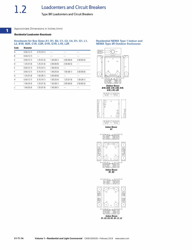
V1-T1-74 Volume 1—Residential and Light Commercial CA08100002E—February 2018 www.eaton.com
1
1
1
1
1
1
1
1
1
1
1
1
1
1
1
1
1
1
1
1
1
1
1
1
1
1
1
1
1
1
1.2 Loadcenters and Circuit Breakers
Type BR Loadcenters and Circuit Breakers
Approximate Dimensions in Inches (mm)
Residential Loadcenter Knockouts
Knockouts for Box Sizes A1, B1, B2, C1, C2, C4, D1, G1, L1, L2, B1R, B2R, C1R, C3R, D1R, G1R, L1R, L2R
Residential NEMA Type 1 Indoor andNEMA Type 3R Outdoor Enclosures
Code Diameter
A 0.50 (12.7) 0.75 (19.1) — — —
B 0.50 (12.7) — — — —
C 0.50 (12.7) 1.25 (31.8) 1.50 (38.1) 2.00 (50.8) 2.50 (63.5)
D 1.25 (31.8) 1.25 (31.8) 2.00 (50.8) 2.50 (63.5) —
E 0.50 (12.7) 0.75 (19.1) 1.00 (25.4) — —
F 0.50 (12.7) 0.75 (19.1) 1.00 (25.4) 1.50 (38.1) 2.00 (50.8)
G 1.25 (31.8) 1.50 (38.1) 2.00 (50.8) — —
H 0.50 (12.7) 0.75 (19.1) 1.00 (25.4) 1.25 (31.8) 1.50 (38.1)
I 1.00 (25.4) 1.25 (31.8) 1.50 (38.1) 2.00 (50.8) 2.50 (63.5)
J 1.00 (25.4) 1.25 (31.8) 1.50 (38.1) — —
J
E
B B B
AB
B B B
BE
JB B B
AB
B B B
BE
J
J
A
B
A
B
J
J
J
A
B
B
B
B
J
B
B
Outdoor BoxesB1R, B2R, C1R, C3R, D1R,
G1R, L1R, L2R
Indoor BoxesB1, B2
Indoor BoxesC1, C2, C4, D1, G1, L1, L2
.45 (11.4) Dia. KO.45 (11.4) Dia. KO
.45 (11.4) Dia. KO.45 (11.4) Dia. KO
A
D
E
A
A
B
B
B
E
D
A
D
E
A
A
B
B
B
E
D
D D
DD
E E
IBB
B
B B
A
AH
BB
B
B B
A
E
A
B
IB B
B
BB
A
AH
B B
B
BB
A
E
A
B
.45 (11.4) Dia. KO.45 (11.4) Dia. KO
.45 (11.4) Dia. KO.45 (11.4) Dia. KO
A
D
E
A
A
B
B
E
D
D D
DD
E E
A
B
B
A
D
E
A
A
B
B
B
E
D
AB
IBB
B
B B
A
AH
BB
B
B B
A
E
A
B
IB B
B
BB
A
AH
B B
B
BB
A
E
A
B
2.06 (52.3) Dia.(125A Max.)3.06 (77.7) Dia.(225A Max.)
Hub
IBB
B
B B
A
AH
BB
B
B B
A
E
A
B
D D D D
.45 (11.4) Dia. KO.45 (11.4) Dia. KO
E E EB
Indoor BoxesA1
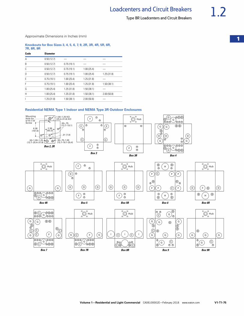
Volume 1—Residential and Light Commercial CA08100002E—February 2018 www.eaton.com V1-T1-75
1
1
1
1
1
1
1
1
1
1
1
1
1
1
1
1
1
1
1
1
1
1
1
1
1
1
1
1
1
1
1.2Loadcenters and Circuit Breakers
Type BR Loadcenters and Circuit Breakers
Approximate Dimensions in Inches (mm)
Knockouts for Box Sizes 3, 4, 5, 6, 7, 9, 2R, 3R, 4R, 5R, 6R, 7R, 8R, 9R
Residential NEMA Type 1 Indoor and NEMA Type 3R Outdoor Enclosures
Code Diameter
A 0.50 (12.7) — — —
B 0.50 (12.7) 0.75 (19.1) — —
C 0.50 (12.7) 0.75 (19.1) 1.00 (25.4) —
D 0.50 (12.7) 0.75 (19.1) 1.00 (25.4) 1.25 (31.8)
E 0.75 (19.1) 1.00 (25.4) 1.25 (31.8) —
F 0.75 (19.1) 1.00 (25.4) 1.25 (31.8) 1.50 (38.1)
G 1.00 (25.4) 1.25 (31.8) 1.50 (38.1) —
H 1.00 (25.4) 1.25 (31.8) 1.50 (38.1) 2.00 (50.8)
I 1.25 (31.8) 1.50 (38.1) 2.00 (50.8) —
Box 2, 2R
R1.00–1.25 KO(25.4–31.8) KO
MountingHole for5/16 (7.9)Screw .50–.75
(12.7–19.1)
2.38(60.3)
.31 (7.9)
.50–.75–1.00(12.7–19.1–25.4)
.50–1.00–1.25(12.7–25.4–31.8)
6.38(161.9)
A
A
A
A
C
EA
A
C
E
F
A
AF
Box 3
A
A
A A
F
Hub
A A A A
A
A A
BBBD
G
G G
Hub
A
A
AA
A
A A A
A
A A
BBB
B
B
B
DG
A A A A
A
A A
BBBD
D D
G
G
G
D
G
G
Box 3R Box 4
Box 4R Box 5 Box 5R Box 6
A
A
A
A
A
A
D D D
D
F
F
A
A
D D D
F
Hub
A
A
B
A
B
B
C
C
F F
FF
AB
F
F
H
A
B
A
BH
Box 6R
F
B B
B
H
Hub
D D
Box 7 Box 7R
A
A
AA
A
AAA
AAA AAA
B B B
A B B
B
B
B
B
C CC
C
C
B C
G
G
GG
G GF
AAA AAA
A B BB C
C
G
G GF
Hub
A A
BC
C
Hub
I
AA
B C
C II
A A
A
A
A A
B
B
B
B
B B
B
C
C
C
G
GG
G
G
G G
G
A
A
B
B
C
GG
G
G
Hub
Box 8R Box 9 Box 9R
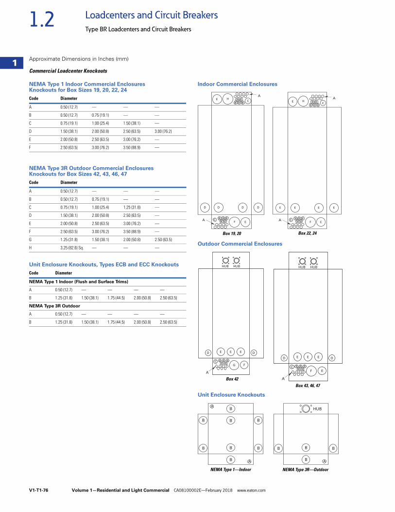
V1-T1-76 Volume 1—Residential and Light Commercial CA08100002E—February 2018 www.eaton.com
1
1
1
1
1
1
1
1
1
1
1
1
1
1
1
1
1
1
1
1
1
1
1
1
1
1
1
1
1
1
1.2 Loadcenters and Circuit Breakers
Type BR Loadcenters and Circuit Breakers
Approximate Dimensions in Inches (mm)
Commercial Loadcenter Knockouts
NEMA Type 1 Indoor Commercial EnclosuresKnockouts for Box Sizes 19, 20, 22, 24
NEMA Type 3R Outdoor Commercial EnclosuresKnockouts for Box Sizes 42, 43, 46, 47
Unit Enclosure Knockouts, Types ECB and ECC Knockouts
Indoor Commercial Enclosures
Outdoor Commercial Enclosures
Unit Enclosure Knockouts
Code Diameter
A 0.50 (12.7) — — —
B 0.50 (12.7) 0.75 (19.1) — —
C 0.75 (19.1) 1.00 (25.4) 1.50 (38.1) —
D 1.50 (38.1) 2.00 (50.8) 2.50 (63.5) 3.00 (76.2)
E 2.00 (50.8) 2.50 (63.5) 3.00 (76.2) —
F 2.50 (63.5) 3.00 (76.2) 3.50 (88.9) —
Code Diameter
A 0.50 (12.7) — — —
B 0.50 (12.7) 0.75 (19.1) — —
C 0.75 (19.1) 1.00 (25.4) 1.25 (31.8) —
D 1.50 (38.1) 2.00 (50.8) 2.50 (63.5) —
E 2.00 (50.8) 2.50 (63.5) 3.00 (76.2) —
F 2.50 (63.5) 3.00 (76.2) 3.50 (88.9) —
G 1.25 (31.8) 1.50 (38.1) 2.00 (50.8) 2.50 (63.5)
H 3.25 (82.6) Sq. — — —
Code Diameter
NEMA Type 1 Indoor (Flush and Surface Trims)
A 0.50 (12.7) — — — —
B 1.25 (31.8) 1.50 (38.1) 1.75 (44.5) 2.00 (50.8) 2.50 (63.5)
NEMA Type 3R Outdoor
A 0.50 (12.7) — — — —
B 1.25 (31.8) 1.50 (38.1) 1.75 (44.5) 2.00 (50.8) 2.50 (63.5)
AH
EFA
B B BB B
C
D D D D
E
C
BB
BB
B
AH
B B BB B
C
E E E E
E
EFA C
BB
BB
B
Box 19, 20 Box 22, 24
G F
E E ED D
C BB
BB
B
A
HUB HUB
F E
E E ED D
C BB
BB
B
A
HUB HUB
Box 42Box 43, 46, 47
B
B
B
B
A
A
B
B
B
B B
B A
B B
HUB
NEMA Type 1—Indoor NEMA Type 3R—Outdoor
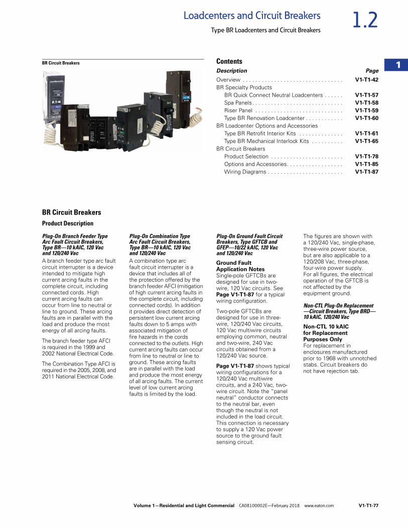
Volume 1—Residential and Light Commercial CA08100002E—February 2018 www.eaton.com V1-T1-77
1
1
1
1
1
1
1
1
1
1
1
1
1
1
1
1
1
1
1
1
1
1
1
1
1
1
1
1
1
1
1.2Loadcenters and Circuit Breakers
Type BR Loadcenters and Circuit Breakers
BR Circuit Breakers ContentsDescription Page
Overview . . . . . . . . . . . . . . . . . . . . . . . . . . . . . . . . V1-T1-42
BR Specialty ProductsBR Quick Connect Neutral Loadcenters . . . . . . V1-T1-57
Spa Panels. . . . . . . . . . . . . . . . . . . . . . . . . . . . . V1-T1-58
Riser Panel . . . . . . . . . . . . . . . . . . . . . . . . . . . . V1-T1-59
Type BR Renovation Loadcenter . . . . . . . . . . . . V1-T1-60
BR Loadcenter Options and AccessoriesType BR Retrofit Interior Kits . . . . . . . . . . . . . . V1-T1-61
Type BR Mechanical Interlock Kits . . . . . . . . . . V1-T1-65
BR Circuit BreakersProduct Selection . . . . . . . . . . . . . . . . . . . . . . . V1-T1-78
Options and Accessories. . . . . . . . . . . . . . . . . . V1-T1-85
Wiring Diagrams . . . . . . . . . . . . . . . . . . . . . . . . V1-T1-87
BR Circuit BreakersProduct Description
Plug-On Branch Feeder Type Arc Fault Circuit Breakers, Type BR—10 kAIC, 120 Vac and 120/240 VacA branch feeder type arc fault circuit interrupter is a device intended to mitigate high current arcing faults in the complete circuit, including connected cords. High current arcing faults can occur from line to neutral or line to ground. These arcing faults are in parallel with the load and produce the most energy of all arcing faults.
The branch feeder type AFCI is required in the 1999 and 2002 National Electrical Code.
The Combination Type AFCI is required in the 2005, 2008, and 2011 National Electrical Code.
Plug-On Combination Type Arc Fault Circuit Breakers, Type BR—10 kAIC, 120 Vac and 120/240 VacA combination type arc fault circuit interrupter is a device that includes all of the protection offered by the branch feeder AFCI (mitigation of high current arcing faults in the complete circuit, including connected cords). In addition it provides direct detection of persistent low current arcing faults down to 5 amps with associated mitigation of fire hazards in the cords connected to the outlets. High current arcing faults can occur from line to neutral or line to ground. These arcing faults are in parallel with the load and produce the most energy of all arcing faults. The current level of low current arcing faults is limited by the load.
Plug-On Ground Fault Circuit Breakers, Type GFTCB and GFEP—10/22 kAIC, 120 Vac and 120/240 Vac
Ground Fault Application NotesSingle-pole GFTCBs are designed for use in two-wire, 120 Vac circuits. See Page V1-T1-87 for a typical wiring configuration.
Two-pole GFTCBs are designed for use in three-wire, 120/240 Vac circuits, 120 Vac multiwire circuits employing common, neutral and two-wire, 240 Vac circuits obtained from a 120/240 Vac source.
Page V1-T1-87 shows typical wiring configurations for a 120/240 Vac multiwire circuits, and a 240 Vac, two-wire circuit. Note the “panel neutral” conductor connects to the neutral bar, even though the neutral is not included in the load circuit. This connection is necessary to supply a 120 Vac power source to the ground fault sensing circuit.
The figures are shown with a 120/240 Vac, single-phase, three-wire power source, but are also applicable to a 120/208 Vac, three-phase, four-wire power supply. For all figures, the electrical operation of the GFTCB is not affected by the equipment ground.
Non-CTL Plug-On Replacement —Circuit Breakers, Type BRD—10 kAIC, 120/240 Vac
Non-CTL 10 kAIC for Replacement Purposes OnlyFor replacement in enclosures manufactured prior to 1968 with unnotched stabs. Circuit breakers do not have rejection tab.
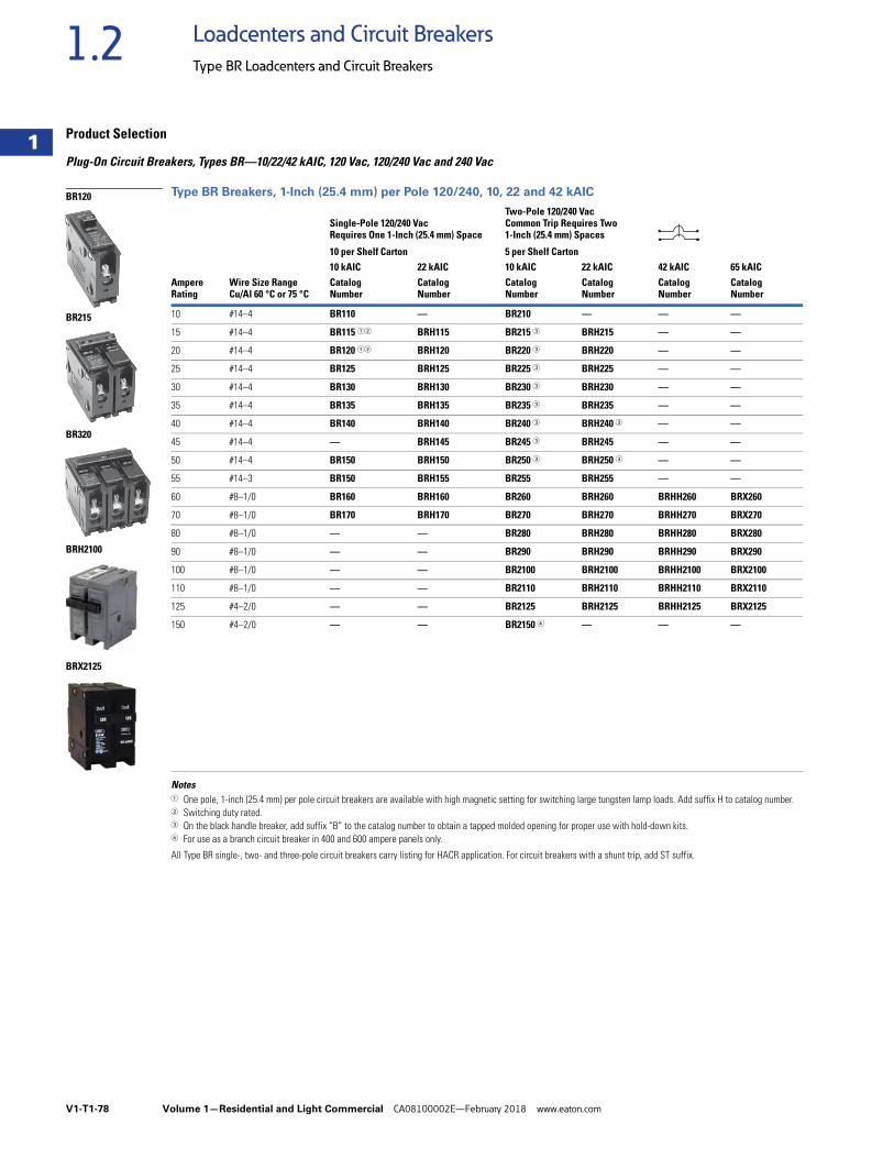
V1-T1-78 Volume 1—Residential and Light Commercial CA08100002E—February 2018 www.eaton.com
1
1
1
1
1
1
1
1
1
1
1
1
1
1
1
1
1
1
1
1
1
1
1
1
1
1
1
1
1
1
1.2 Loadcenters and Circuit Breakers
Type BR Loadcenters and Circuit Breakers
Product Selection
Plug-On Circuit Breakers, Types BR—10/22/42 kAIC, 120 Vac, 120/240 Vac and 240 Vac
Type BR Breakers, 1-Inch (25.4 mm) per Pole 120/240, 10, 22 and 42 kAIC
Notes1 One pole, 1-inch (25.4 mm) per pole circuit breakers are available with high magnetic setting for switching large tungsten lamp loads. Add suffix H to catalog number.2 Switching duty rated.3 On the black handle breaker, add suffix “B” to the catalog number to obtain a tapped molded opening for proper use with hold-down kits.4 For use as a branch circuit breaker in 400 and 600 ampere panels only.
All Type BR single-, two- and three-pole circuit breakers carry listing for HACR application. For circuit breakers with a shunt trip, add ST suffix.
AmpereRating
Wire Size RangeCu/Al 60 °C or 75 °C
Single-Pole 120/240 Vac Requires One 1-Inch (25.4 mm) Space
Two-Pole 120/240 Vac Common Trip Requires Two 1-Inch (25.4 mm) Spaces
10 per Shelf Carton 5 per Shelf Carton10 kAIC 22 kAIC 10 kAIC 22 kAIC 42 kAIC 65 kAICCatalogNumber
CatalogNumber
CatalogNumber
CatalogNumber
CatalogNumber
CatalogNumber
10 #14–4 BR110 — BR210 — — —
15 #14–4 BR115 12 BRH115 BR215 3 BRH215 — —
20 #14–4 BR120 12 BRH120 BR220 3 BRH220 — —
25 #14–4 BR125 BRH125 BR225 3 BRH225 — —
30 #14–4 BR130 BRH130 BR230 3 BRH230 — —
35 #14–4 BR135 BRH135 BR235 3 BRH235 — —
40 #14–4 BR140 BRH140 BR240 3 BRH240 3 — —
45 #14–4 — BRH145 BR245 3 BRH245 — —
50 #14–4 BR150 BRH150 BR250 3 BRH250 3 — —
55 #14–3 BR150 BRH155 BR255 BRH255 — —
60 #8–1/0 BR160 BRH160 BR260 BRH260 BRHH260 BRX260
70 #8–1/0 BR170 BRH170 BR270 BRH270 BRHH270 BRX270
80 #8–1/0 — — BR280 BRH280 BRHH280 BRX280
90 #8–1/0 — — BR290 BRH290 BRHH290 BRX290
100 #8–1/0 — — BR2100 BRH2100 BRHH2100 BRX2100
110 #8–1/0 — — BR2110 BRH2110 BRHH2110 BRX2110
125 #4–2/0 — — BR2125 BRH2125 BRHH2125 BRX2125
150 #4–2/0 — — BR2150 4 — — —
BR120
BR215
BR320
BRH2100
BRX2125
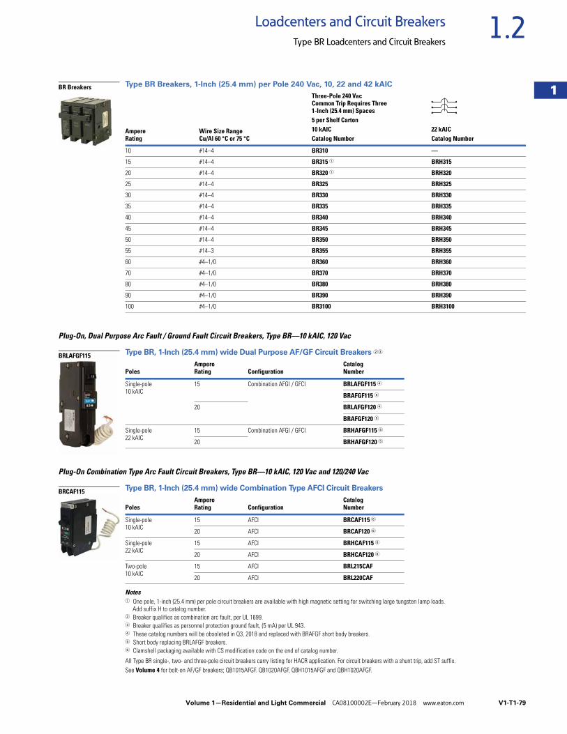
Volume 1—Residential and Light Commercial CA08100002E—February 2018 www.eaton.com V1-T1-79
1
1
1
1
1
1
1
1
1
1
1
1
1
1
1
1
1
1
1
1
1
1
1
1
1
1
1
1
1
1
1.2Loadcenters and Circuit Breakers
Type BR Loadcenters and Circuit Breakers
Type BR Breakers, 1-Inch (25.4 mm) per Pole 240 Vac, 10, 22 and 42 kAIC
Plug-On, Dual Purpose Arc Fault / Ground Fault Circuit Breakers, Type BR—10 kAIC, 120 Vac
Type BR, 1-Inch (25.4 mm) wide Dual Purpose AF/GF Circuit Breakers 23
Plug-On Combination Type Arc Fault Circuit Breakers, Type BR—10 kAIC, 120 Vac and 120/240 Vac
Type BR, 1-Inch (25.4 mm) wide Combination Type AFCI Circuit Breakers
Notes1 One pole, 1-inch (25.4 mm) per pole circuit breakers are available with high magnetic setting for switching large tungsten lamp loads.
Add suffix H to catalog number.2 Breaker qualifies as combination arc fault, per UL 1699.3 Breaker qualifies as personnel protection ground fault, (5 mA) per UL 943.4 These catalog numbers will be obsoleted in Q3, 2018 and replaced with BRAFGF short body breakers.5 Short body replacing BRLAFGF breakers.6 Clamshell packaging available with CS modification code on the end of catalog number.
All Type BR single-, two- and three-pole circuit breakers carry listing for HACR application. For circuit breakers with a shunt trip, add ST suffix.See Volume 4 for bolt-on AF/GF breakers; QB1015AFGF. QB1020AFGF, QBH1015AFGF and QBH1020AFGF.
AmpereRating
Wire Size RangeCu/Al 60 °C or 75 °C
Three-Pole 240 VacCommon Trip Requires Three 1-Inch (25.4 mm) Spaces5 per Shelf Carton10 kAIC 22 kAICCatalog Number Catalog Number
10 #14–4 BR310 —
15 #14–4 BR315 1 BRH315
20 #14–4 BR320 1 BRH320
25 #14–4 BR325 BRH325
30 #14–4 BR330 BRH330
35 #14–4 BR335 BRH335
40 #14–4 BR340 BRH340
45 #14–4 BR345 BRH345
50 #14–4 BR350 BRH350
55 #14–3 BR355 BRH355
60 #4–1/0 BR360 BRH360
70 #4–1/0 BR370 BRH370
80 #4–1/0 BR380 BRH380
90 #4–1/0 BR390 BRH390
100 #4–1/0 BR3100 BRH3100
PolesAmpereRating Configuration
CatalogNumber
Single-pole10 kAIC
15 Combination AFGI / GFCI BRLAFGF115 4
BRAFGF115 5
20 BRLAFGF120 4
BRAFGF120 5
Single-pole22 kAIC
15 Combination AFGI / GFCI BRHAFGF115 5
20 BRHAFGF120 5
PolesAmpereRating Configuration
CatalogNumber
Single-pole10 kAIC
15 AFCI BRCAF115 6
20 AFCI BRCAF120 6
Single-pole22 kAIC
15 AFCI BRHCAF115 6
20 AFCI BRHCAF120 6
Two-pole10 kAIC
15 AFCI BRL215CAF
20 AFCI BRL220CAF
BR Breakers
BRLAFGF115
BRCAF115
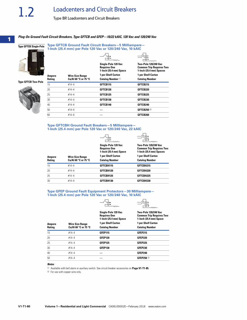
V1-T1-80 Volume 1—Residential and Light Commercial CA08100002E—February 2018 www.eaton.com
1
1
1
1
1
1
1
1
1
1
1
1
1
1
1
1
1
1
1
1
1
1
1
1
1
1
1
1
1
1
1.2 Loadcenters and Circuit Breakers
Type BR Loadcenters and Circuit Breakers
Plug-On Ground Fault Circuit Breakers, Type GFTCB and GFEP—10/22 kAIC, 120 Vac and 120/240 Vac
Type GFTCB Ground Fault Circuit Breakers—5 Milliampere—1-Inch (25.4 mm) per Pole 120 Vac or 120/240 Vac, 10 kAIC
Type GFTCBH Ground Fault Breakers—5 Milliampere—1-Inch (25.4 mm) per Pole 120 Vac or 120/240 Vac, 22 kAIC
Type GFEP Ground Fault Equipment Protectors—30 Milliampere—1-Inch (25.4 mm) per Pole 120 Vac or 120/240 Vac, 10 kAIC
Notes1 Available with bell alarm or auxiliary switch. See circuit breaker accessories on Page V1-T1-85.2 For use with copper wire only.
AmpereRating
Wire Size RangeCu/Al 60 °C or 75 °C
Single-Pole 120 VacRequires One 1-Inch (25.4 mm) Space
Two-Pole 120/240 VacCommon Trip Requires Two1-Inch (25.4 mm) Spaces
1 per Shelf Carton 1 per Shelf CartonCatalog Number 1 Catalog Number
15 #14–4 GFTCB115 GFTCB215
20 #14–4 GFTCB120 GFTCB220
25 #14–4 GFTCB125 GFTCB225
30 #14–4 GFTCB130 GFTCB230
40 #14–4 GFTCB140 GFTCB240
50 #14–4 — GFTCB250 2
60 #14–6 — GFTCB260
AmpereRating
Wire Size RangeCu/Al 60 °C or 75 °C
Single-Pole 120 VacRequires One1-Inch (25.4 mm) Space
Two-Pole 120/240 VacCommon Trip Requires Two1-Inch (25.4 mm) Spaces
1 per Shelf Carton 1 per Shelf CartonCatalog Number Catalog Number
15 #14–4 GFTCBH115 GFTCBH215
20 #14–4 GFTCBH120 GFTCBH220
25 #14–4 GFTCBH125 GFTCBH225
30 #14–4 GFTCBH130 GFTCBH230
AmpereRating
Wire Size RangeCu/Al 60 °C or 75 °C
Single-Pole 120 VacRequires One 1-Inch (25.4 mm) Space
Two-Pole 120/240 VacCommon Trip Requires Two 1-Inch (25.4 mm) Space
1 per Shelf Carton 1 per Shelf CartonCatalog Number Catalog Number
15 #14–4 GFEP115 GFEP215
20 #14–4 GFEP120 GFEP220
25 #14–4 GFEP125 GFEP225
30 #14–4 GFEP130 GFEP230
40 #14–4 — GFEP240
50 #14–4 — GFEP250 2
Type GFTCB Single-Pole
Type GFTCB Two-Pole
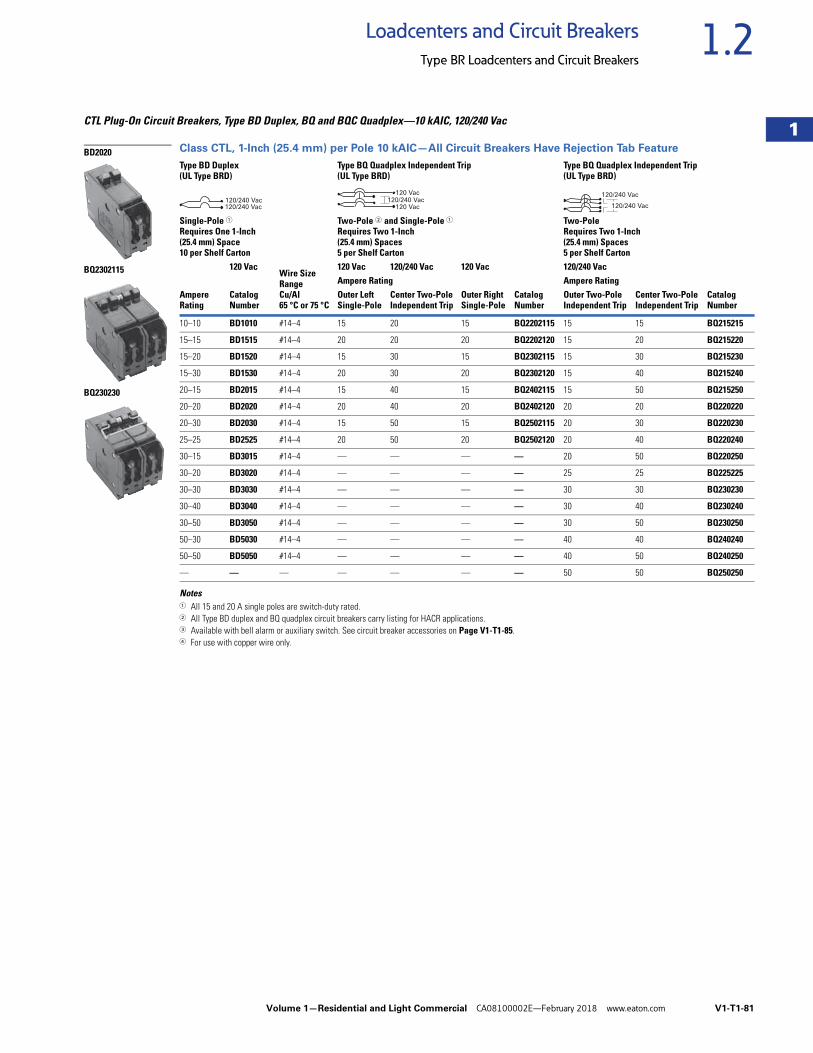
Volume 1—Residential and Light Commercial CA08100002E—February 2018 www.eaton.com V1-T1-81
1
1
1
1
1
1
1
1
1
1
1
1
1
1
1
1
1
1
1
1
1
1
1
1
1
1
1
1
1
1
1.2Loadcenters and Circuit Breakers
Type BR Loadcenters and Circuit Breakers
CTL Plug-On Circuit Breakers, Type BD Duplex, BQ and BQC Quadplex—10 kAIC, 120/240 Vac
Class CTL, 1-Inch (25.4 mm) per Pole 10 kAIC—All Circuit Breakers Have Rejection Tab Feature
Notes1 All 15 and 20 A single poles are switch-duty rated.2 All Type BD duplex and BQ quadplex circuit breakers carry listing for HACR applications.3 Available with bell alarm or auxiliary switch. See circuit breaker accessories on Page V1-T1-85.4 For use with copper wire only.
Type BD Duplex(UL Type BRD)
Wire Size RangeCu/Al 65 °C or 75 °C
Type BQ Quadplex Independent Trip (UL Type BRD)
Type BQ Quadplex Independent Trip (UL Type BRD)
Single-Pole 1Requires One 1-Inch(25.4 mm) Space10 per Shelf Carton
Two-Pole 2 and Single-Pole 1Requires Two 1-Inch(25.4 mm) Spaces5 per Shelf Carton
Two-PoleRequires Two 1-Inch(25.4 mm) Spaces5 per Shelf Carton
AmpereRating
120 Vac 120 Vac 120/240 Vac 120 Vac
CatalogNumber
120/240 Vac
CatalogNumber
CatalogNumber
Ampere Rating Ampere RatingOuter LeftSingle-Pole
Center Two-PoleIndependent Trip
Outer RightSingle-Pole
Outer Two-PoleIndependent Trip
Center Two-PoleIndependent Trip
10–10 BD1010 #14–4 15 20 15 BQ2202115 15 15 BQ215215
15–15 BD1515 #14–4 20 20 20 BQ2202120 15 20 BQ215220
15–20 BD1520 #14–4 15 30 15 BQ2302115 15 30 BQ215230
15–30 BD1530 #14–4 20 30 20 BQ2302120 15 40 BQ215240
20–15 BD2015 #14–4 15 40 15 BQ2402115 15 50 BQ215250
20–20 BD2020 #14–4 20 40 20 BQ2402120 20 20 BQ220220
20–30 BD2030 #14–4 15 50 15 BQ2502115 20 30 BQ220230
25–25 BD2525 #14–4 20 50 20 BQ2502120 20 40 BQ220240
30–15 BD3015 #14–4 — — — — 20 50 BQ220250
30–20 BD3020 #14–4 — — — — 25 25 BQ225225
30–30 BD3030 #14–4 — — — — 30 30 BQ230230
30–40 BD3040 #14–4 — — — — 30 40 BQ230240
30–50 BD3050 #14–4 — — — — 30 50 BQ230250
50–30 BD5030 #14–4 — — — — 40 40 BQ240240
50–50 BD5050 #14–4 — — — — 40 50 BQ240250
— — — — — — — 50 50 BQ250250
BD2020
BQ2302115
BQ230230
120/240 Vac120/240 Vac
120 Vac
120 Vac120/240 Vac
120/240 Vac
120/240 Vac
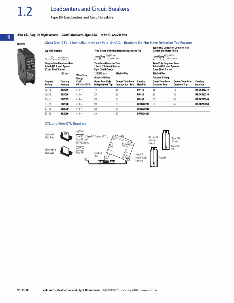
V1-T1-82 Volume 1—Residential and Light Commercial CA08100002E—February 2018 www.eaton.com
1
1
1
1
1
1
1
1
1
1
1
1
1
1
1
1
1
1
1
1
1
1
1
1
1
1
1
1
1
1
1.2 Loadcenters and Circuit Breakers
Type BR Loadcenters and Circuit Breakers
Non-CTL Plug-On Replacement—Circuit Breakers, Type BRD—10 kAIC, 120/240 Vac
Class Non-CTL, 1-Inch (25.4 mm) per Pole 10 kAIC—Breakers Do Not Have Rejection Tab Feature
CTL and Non-CTL Breakers
Type BR Duplex
Wire SizeRangeCu/Al65 °C or 75 °C
Type Brand BRD Quadplex Independent TripType BRD Quadplex Common Trip Center and Outer Poles
Single-Pole Requires One 1-Inch (25.4 mm) Space10 per Shelf Carton
Two-Pole Requires Two 1-Inch (25.4 mm) Spaces5 per Shelf Carton
Two-Pole Requires Two 1-Inch (25.4 mm) Spaces5 per Shelf Carton
Ampere Rating
120 Vac 120/240 Vac 120/240 Vac
CatalogNumber
120/240 Vac
CatalogNumber
CatalogNumber
Ampere Rating Ampere RatingOuter Two-PoleIndependent Trip
Center Two-PoleIndependent Trip
Outer Two-PoleCommon Trip
Center Two-PoleCommon Trip
15–15 BR1515 #14–4 15 15 BR415 15 15 BRDC215215
15–20 BR1520 #14–4 20 20 BR420 30 30 BRDC230230
20–15 BR2015 #14–4 30 30 BR430 30 40 BRDC230240
20–20 BR2020 #14–4 20 30 BRD220230 30 50 BRDC230250
30–30 BR3030 #14–4 30 40 BRD230240 — — —
30–50 BR3050 #14–4 30 50 BRD230250 — — —
BR2020
120/240 Vac120/240 Vac
120/240 Vac
120/240 Vac
120/240 Vac
120/240 Vac
NotchedBus Stab
UnnotchedBus Stab
Type BR or Type BD Duplex, (CTL), Type BQ and BQC Quadplex
Type BR Notched Stab Non-CTL
Non-CircuitLimiting
Type BR
Type BDDuplex
RejectionTab
CTL CircuitLimitingFeature
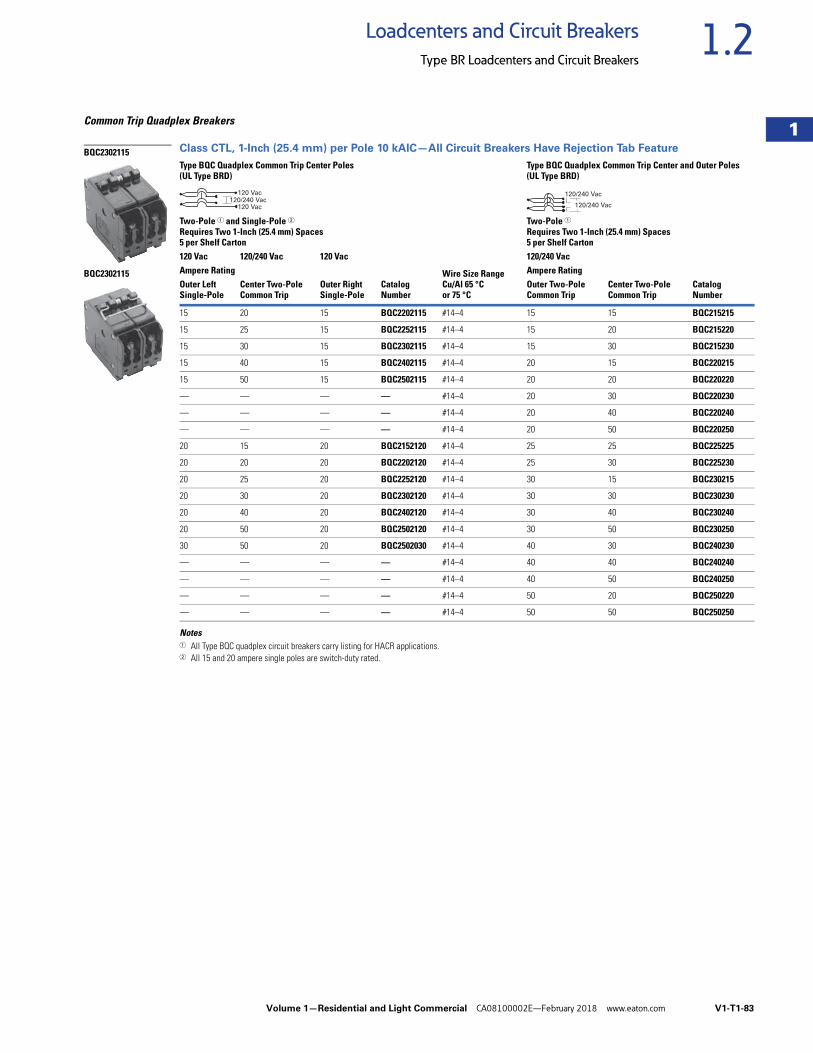
Volume 1—Residential and Light Commercial CA08100002E—February 2018 www.eaton.com V1-T1-83
1
1
1
1
1
1
1
1
1
1
1
1
1
1
1
1
1
1
1
1
1
1
1
1
1
1
1
1
1
1
1.2Loadcenters and Circuit Breakers
Type BR Loadcenters and Circuit Breakers
Common Trip Quadplex Breakers
Class CTL, 1-Inch (25.4 mm) per Pole 10 kAIC—All Circuit Breakers Have Rejection Tab Feature
Notes1 All Type BQC quadplex circuit breakers carry listing for HACR applications.2 All 15 and 20 ampere single poles are switch-duty rated.
Type BQC Quadplex Common Trip Center Poles(UL Type BRD)
Wire Size RangeCu/Al 65 °C or 75 °C
Type BQC Quadplex Common Trip Center and Outer Poles(UL Type BRD)
Two-Pole 1 and Single-Pole 2Requires Two 1-Inch (25.4 mm) Spaces5 per Shelf Carton
Two-Pole 1Requires Two 1-Inch (25.4 mm) Spaces5 per Shelf Carton
120 Vac 120/240 Vac 120 Vac
CatalogNumber
120/240 Vac
CatalogNumber
Ampere Rating Ampere RatingOuter LeftSingle-Pole
Center Two-PoleCommon Trip
Outer RightSingle-Pole
Outer Two-PoleCommon Trip
Center Two-PoleCommon Trip
15 20 15 BQC2202115 #14–4 15 15 BQC215215
15 25 15 BQC2252115 #14–4 15 20 BQC215220
15 30 15 BQC2302115 #14–4 15 30 BQC215230
15 40 15 BQC2402115 #14–4 20 15 BQC220215
15 50 15 BQC2502115 #14–4 20 20 BQC220220
— — — — #14–4 20 30 BQC220230
— — — — #14–4 20 40 BQC220240
— — — — #14–4 20 50 BQC220250
20 15 20 BQC2152120 #14–4 25 25 BQC225225
20 20 20 BQC2202120 #14–4 25 30 BQC225230
20 25 20 BQC2252120 #14–4 30 15 BQC230215
20 30 20 BQC2302120 #14–4 30 30 BQC230230
20 40 20 BQC2402120 #14–4 30 40 BQC230240
20 50 20 BQC2502120 #14–4 30 50 BQC230250
30 50 20 BQC2502030 #14–4 40 30 BQC240230
— — — — #14–4 40 40 BQC240240
— — — — #14–4 40 50 BQC240250
— — — — #14–4 50 20 BQC250220
— — — — #14–4 50 50 BQC250250
BQC2302115
BQC2302115
120 Vac
120 Vac120/240 Vac
120/240 Vac
120/240 Vac
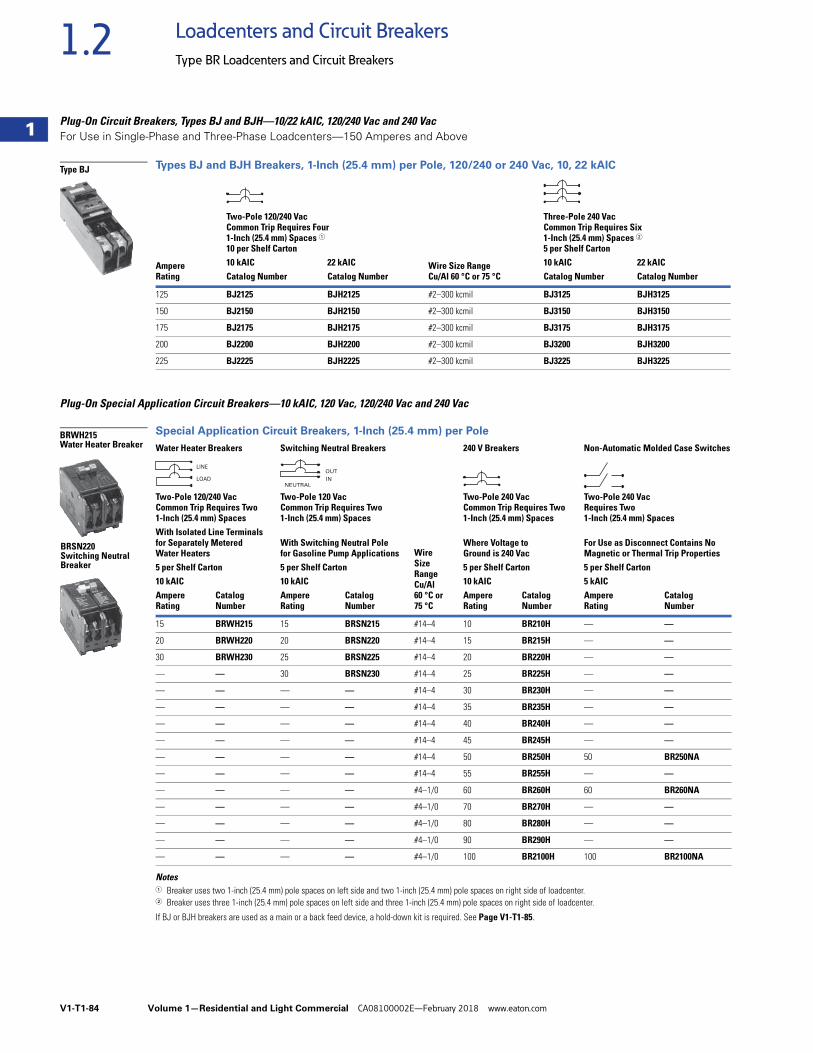
V1-T1-84 Volume 1—Residential and Light Commercial CA08100002E—February 2018 www.eaton.com
1
1
1
1
1
1
1
1
1
1
1
1
1
1
1
1
1
1
1
1
1
1
1
1
1
1
1
1
1
1
1.2 Loadcenters and Circuit Breakers
Type BR Loadcenters and Circuit Breakers
Plug-On Circuit Breakers, Types BJ and BJH—10/22 kAIC, 120/240 Vac and 240 VacFor Use in Single-Phase and Three-Phase Loadcenters—150 Amperes and Above
Types BJ and BJH Breakers, 1-Inch (25.4 mm) per Pole, 120/240 or 240 Vac, 10, 22 kAIC
Plug-On Special Application Circuit Breakers—10 kAIC, 120 Vac, 120/240 Vac and 240 Vac
Special Application Circuit Breakers, 1-Inch (25.4 mm) per Pole
Notes1 Breaker uses two 1-inch (25.4 mm) pole spaces on left side and two 1-inch (25.4 mm) pole spaces on right side of loadcenter.2 Breaker uses three 1-inch (25.4 mm) pole spaces on left side and three 1-inch (25.4 mm) pole spaces on right side of loadcenter.
If BJ or BJH breakers are used as a main or a back feed device, a hold-down kit is required. See Page V1-T1-85.
AmpereRating
Wire Size RangeCu/Al 60 °C or 75 °C
Two-Pole 120/240 VacCommon Trip Requires Four 1-Inch (25.4 mm) Spaces 110 per Shelf Carton
Three-Pole 240 VacCommon Trip Requires Six 1-Inch (25.4 mm) Spaces 25 per Shelf Carton
10 kAIC 22 kAIC 10 kAIC 22 kAICCatalog Number Catalog Number Catalog Number Catalog Number
125 BJ2125 BJH2125 #2–300 kcmil BJ3125 BJH3125
150 BJ2150 BJH2150 #2–300 kcmil BJ3150 BJH3150
175 BJ2175 BJH2175 #2–300 kcmil BJ3175 BJH3175
200 BJ2200 BJH2200 #2–300 kcmil BJ3200 BJH3200
225 BJ2225 BJH2225 #2–300 kcmil BJ3225 BJH3225
Water Heater Breakers Switching Neutral Breakers
Wire SizeRangeCu/Al60 °C or 75 °C
240 V Breakers Non-Automatic Molded Case Switches
Two-Pole 120/240 VacCommon Trip Requires Two 1-Inch (25.4 mm) Spaces
Two-Pole 120 VacCommon Trip Requires Two 1-Inch (25.4 mm) Spaces
Two-Pole 240 VacCommon Trip Requires Two 1-Inch (25.4 mm) Spaces
Two-Pole 240 VacRequires Two 1-Inch (25.4 mm) Spaces
With Isolated Line Terminals for Separately Metered Water Heaters
With Switching Neutral Pole for Gasoline Pump Applications
Where Voltage to Ground is 240 Vac
For Use as Disconnect Contains NoMagnetic or Thermal Trip Properties
5 per Shelf Carton 5 per Shelf Carton 5 per Shelf Carton 5 per Shelf Carton10 kAIC 10 kAIC 10 kAIC 5 kAICAmpere Rating
Catalog Number
Ampere Rating
Catalog Number
Ampere Rating
Catalog Number
Ampere Rating
Catalog Number
15 BRWH215 15 BRSN215 #14–4 10 BR210H — —
20 BRWH220 20 BRSN220 #14–4 15 BR215H — —
30 BRWH230 25 BRSN225 #14–4 20 BR220H — —
— — 30 BRSN230 #14–4 25 BR225H — —
— — — — #14–4 30 BR230H — —
— — — — #14–4 35 BR235H — —
— — — — #14–4 40 BR240H — —
— — — — #14–4 45 BR245H — —
— — — — #14–4 50 BR250H 50 BR250NA
— — — — #14–4 55 BR255H — —
— — — — #4–1/0 60 BR260H 60 BR260NA
— — — — #4–1/0 70 BR270H — —
— — — — #4–1/0 80 BR280H — —
— — — — #4–1/0 90 BR290H — —
— — — — #4–1/0 100 BR2100H 100 BR2100NA
Type BJ
BRWH215Water Heater Breaker
BRSN220Switching Neutral Breaker
LINE
LOAD
OUT
INNEUTRAL
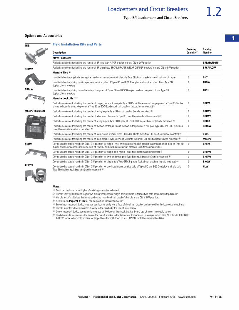
Volume 1—Residential and Light Commercial CA08100002E—February 2018 www.eaton.com V1-T1-85
1
1
1
1
1
1
1
1
1
1
1
1
1
1
1
1
1
1
1
1
1
1
1
1
1
1
1
1
1
1
1.2Loadcenters and Circuit Breakers
Type BR Loadcenters and Circuit Breakers
Options and Accessories
Field Installation Kits and Parts
Notes1 Must be purchased in multiples of ordering quantities indicated.2 Handle ties: typically used to join two similar independent single-pole breakers to form a two-pole noncommon trip breaker.3 Handle lockoffs: devices that use a padlock to lock the circuit breaker’s handle in the ON or OFF position.4 See table on Page V1-T1-86 for handle position changeability chart.5 Escutcheon mounted: device mounted semipermanently to the face of the circuit breaker and secured by the loadcenter deadfront.6 Handle mounted: device mounted directly to the handle by the use of a set screw.7 Screw mounted: device permanently mounted to the face of the circuit breaker by the use of a non-removable screw.8 Hold-down kits: devices used to secure the circuit breaker to the loadcenter for back-feed main application. See NEC Article 408.36(D).
Add “B” suffix to two-pole breaker for tapped hole for hold-down kit (ex. BR230B) for BR breakers below 60 A.
DescriptionOrderingQuantity 1
CatalogNumber
New Products
Padlockable device for locking the handle of BR long body AF/GF breaker into the ON or OFF position BRLAFGFLOFF
Padlockable device for locking the handle of BR short body BRCAF, BRAFGF, QBCAF, QBAFGF breakers into the ON or OFF position BRCAFLOFF
Handle Ties 2
Handle tie bar for physically joining the handles of two adjacent single-pole Type BR circuit breakers (metal cylinder pin type) 10 BHT
Handle tie bar for joining two independent outside poles of Types BQ and BQC Quadplex and outside poles of two Type BD duplex circuit breakers
10 THOW
Handle tie bar for joining two adjacent outside poles of Types BQ and BQC Quadplex and outside poles of two Type BD duplex circuit breakers
10 THS1
Handle Lockoffs 34
Padlockable device for locking the handle of single-, two- or three-pole Type BR Circuit Breakers and single-pole of a Type BD Duplex or one independent outside pole of a Type BQ or BQC Quadplex circuit breakers (escutcheon mounted) 5
10 BRLW
Padlockable device for locking the handle of a single-pole Type BR circuit breaker (handle mounted) 6 10 BRLW1
Padlockable device for locking the handle of a two- and three-pole Type BR circuit breaker (handle mounted) 6 10 BRLW2
Padlockable device for locking the handle of a single-pole Type BD Duplex, BQ or BQC Quadplex breaker (handle mounted) 6 10 BRDL1
Padlockable device for locking the handle of the two center poles and the two outer poles of a two-pole Types BQ and BQC quadplex circuit breakers (escutcheon mounted) 5
10 BRQLW
Padlockable device for locking the handle of main circuit breaker Types CC and CHH into the ON or OFF position (screw mounted) 7 1 CCPL
Padlockable device for locking the handle of main breaker Types BW and CSR into the ON or OFF position (escutcheon mounted) 5 1 MCBPL
Device used to secure handle in ON or OFF position for single-, two- or three-pole Type BR circuit breakers and single-pole of Type BD duplex and one independent outside pole of Type BQ or BQC Quadplex circuit breakers (escutcheon mounted) 5
10 BHLW
Device used to secure handle in ON or OFF position for single-pole Type BR circuit breakers (handle mounted) 6 10 BHLW1
Device used to secure handle in ON or OFF position for two- and three-pole Type BR circuit breakers (handle mounted) 6 10 BHLW2
Device used to secure handle in ON or OFF position for single-pole Type GFTCB ground fault circuit breakers (handle mounted) 6 10 BHGW
Device used to secure handle in ON or OFF position for one independent outside pole of Types BQ and BQC Quadplex or single-pole Type BD duplex circuit breakers (handle mounted) 6
10 HLW1
THS1
BHLW2
BRQLW
MCBPL (Installed)
BHLW
BRLW2
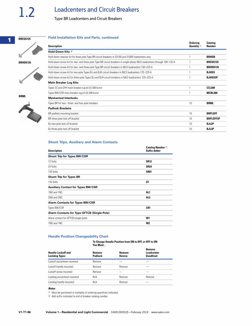
V1-T1-86 Volume 1—Residential and Light Commercial CA08100002E—February 2018 www.eaton.com
1
1
1
1
1
1
1
1
1
1
1
1
1
1
1
1
1
1
1
1
1
1
1
1
1
1
1
1
1
1
1.2 Loadcenters and Circuit Breakers
Type BR Loadcenters and Circuit Breakers
Field Installation Kits and Parts, continued
Shunt Trips, Auxiliary and Alarm Contacts
Handle Position Changeability Chart
Notes1 Must be purchased in multiples of ordering quantities indicated.2 Add suffix indicated to end of breaker catalog number.
DescriptionOrderingQuantity 1
CatalogNumber
Hold-Down Kits 8
Hold-down retainer kit for three-pole Type BR circuit breakers in S3100 and 3100R loadcenters only 1 BRHDB
Hold-down screw kit for two- and three-pole Type BR circuit breakers in single-phase MLO loadcenters through 100–125 A 1 BREQS125
Hold-down screw kit for two- and three-pole Type BR circuit breakers in MLO loadcenters 150–225 A 1 BRHDK125
Hold-down screw kit for two-pole Types BJ and BJH circuit breakers in MLO loadcenters 125–225 A 1 BJHDS
Hold-down screw kit for three-pole Types BJ and BJH circuit breakers in MLO loadcenters 125–225 A 1 BJHDS3P
Main Breaker Lug Kits
Types CC and CHH main breaker lug kit (2) 300 kcmil 1 CCL300
Types BW/CSR main breaker lug kit (2) 300 kcmil 1 MCBL300
Mechanical Interlocks
Types BR for two-, three- and four-pole breakers 10 BRML
Padlock Brackets
BR padlock mounting bracket 10 BRPLOFF
BR three-pole lock-off bracket 10 BRPLOFF3P
BJ two-pole lock-off bracket 10 BJL2P
BJ three-pole lock-off bracket 10 BJL3P
DescriptionCatalog Number 2Suffix Adder
Shunt Trip for Types BW/CSR
12 Volts SR12
24 Volts SR24
120 Volts SR01
Shunt Trip for Types BR
120 Volts ST
Auxiliary Contact for Types BW/CSR
1NO and 1NC AL1
2NO and 2NC AL2
Alarm Contacts for Types BW/CSR
Types BW/CSR CR1
Alarm Contacts for Type GFTCB (Single-Pole)
Alarm contact for GFTCB (single-pole) W1
1NO and 1NC W2
Handle Lockoff and Lockdog Types
To Change Handle Position from ON to OFF, or OFF to ONYou Must...
RemovePadlock
RemoveDevice
RemoveLoadcenterDeadfront
Lockoff escutcheon mounted Remove — —
Lockoff handle mounted Remove Remove —
Lockoff screw mounted Remove — —
Lockdog escutcheon mounted N/A Remove Remove
Lockdog handle mounted N/A Remove —
BRML
BREQS125
BRHDK125
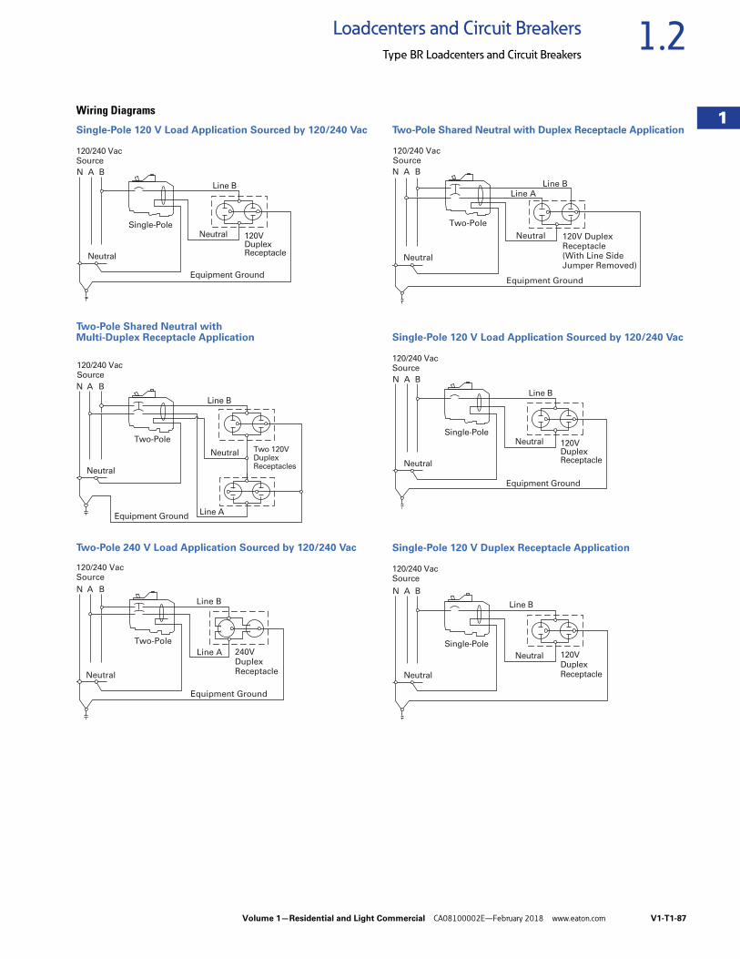
Volume 1—Residential and Light Commercial CA08100002E—February 2018 www.eaton.com V1-T1-87
1
1
1
1
1
1
1
1
1
1
1
1
1
1
1
1
1
1
1
1
1
1
1
1
1
1
1
1
1
1
1.2Loadcenters and Circuit Breakers
Type BR Loadcenters and Circuit Breakers
Wiring Diagrams
Single-Pole 120 V Load Application Sourced by 120/240 Vac
Two-Pole Shared Neutral with Multi-Duplex Receptacle Application
Two-Pole 240 V Load Application Sourced by 120/240 Vac
Two-Pole Shared Neutral with Duplex Receptacle Application
Single-Pole 120 V Load Application Sourced by 120/240 Vac
Single-Pole 120 V Duplex Receptacle Application
N A B
120/240 VacSource
120VDuplexReceptacle
Single-Pole
Line B
Neutral
Neutral
Equipment Ground
N A B
120/240 VacSource
Two 120VDuplexReceptacles
Two-Pole
Line B
Line A
Neutral
Neutral
Equipment Ground
Line B
N A B
120/240 VacSource
Line A 240VDuplexReceptacle
Two-Pole
Neutral
Equipment Ground
N A B
120/240 VacSource
Line A
120V DuplexReceptacle(With Line SideJumper Removed)
Two-Pole
Line B
Neutral
Neutral
Equipment Ground
N A B
120/240 VacSource
120VDuplexReceptacle
Single-Pole
Line B
Neutral
Neutral
Equipment Ground
N A B
120/240 VacSource
120VDuplexReceptacle
Single-Pole
Line B
Neutral
Neutral
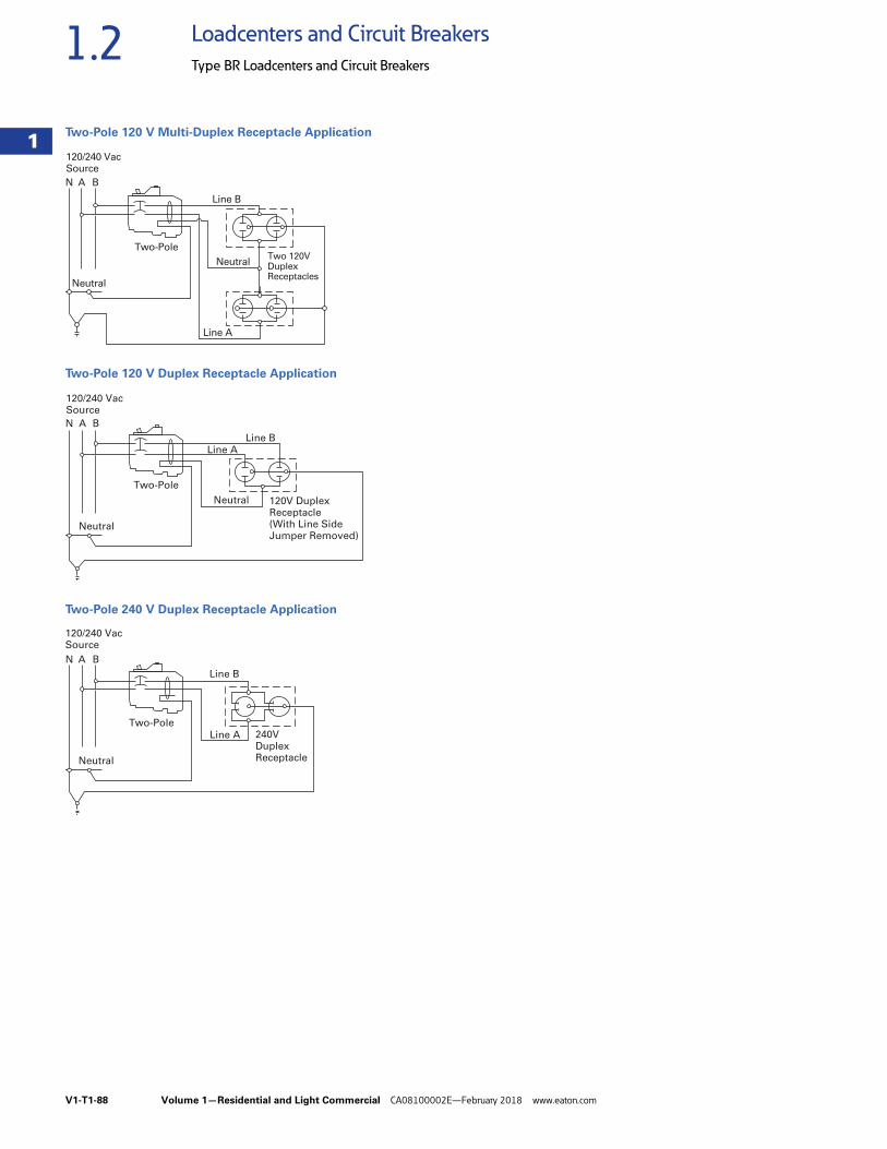
V1-T1-88 Volume 1—Residential and Light Commercial CA08100002E—February 2018 www.eaton.com
1
1
1
1
1
1
1
1
1
1
1
1
1
1
1
1
1
1
1
1
1
1
1
1
1
1
1
1
1
1
1.2 Loadcenters and Circuit Breakers
Type BR Loadcenters and Circuit Breakers
Two-Pole 120 V Multi-Duplex Receptacle Application
Two-Pole 120 V Duplex Receptacle Application
Two-Pole 240 V Duplex Receptacle Application
N A B
120/240 VacSource
Two 120VDuplexReceptacles
Two-Pole
Line B
Line A
Neutral
Neutral
N A B
120/240 VacSource
Line A
120V DuplexReceptacle(With Line SideJumper Removed)
Two-Pole
Line B
Neutral
Neutral
Line B
N A B
120/240 VacSource
Line A 240VDuplexReceptacle
Two-Pole
Neutral
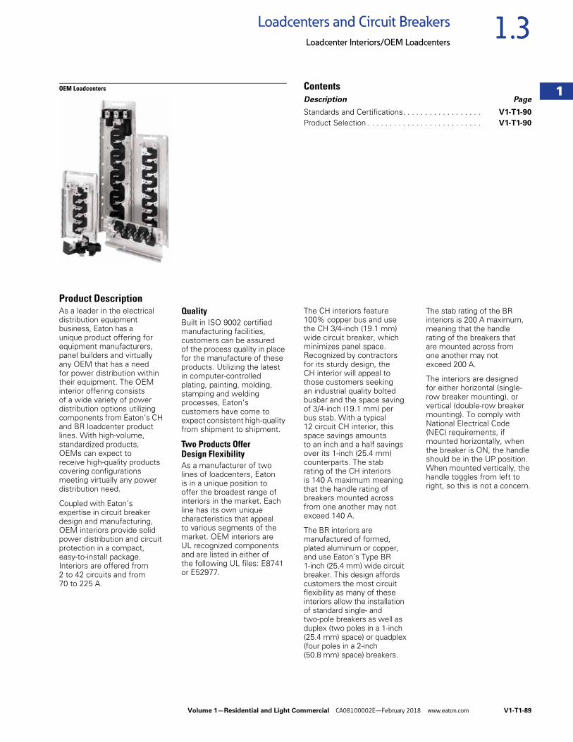
Volume 1—Residential and Light Commercial CA08100002E—February 2018 www.eaton.com V1-T1-89
1
1
1
1
1
1
1
1
1
1
1
1
1
1
1
1
1
1
1
1
1
1
1
1
1
1
1
1
1
1
1.3Loadcenters and Circuit Breakers
Loadcenter Interiors/OEM Loadcenters
OEM Loadcenters ContentsDescription Page
Standards and Certifications. . . . . . . . . . . . . . . . . . V1-T1-90
Product Selection . . . . . . . . . . . . . . . . . . . . . . . . . . V1-T1-90
Product DescriptionAs a leader in the electrical distribution equipment business, Eaton has a unique product offering for equipment manufacturers, panel builders and virtually any OEM that has a need for power distribution within their equipment. The OEM interior offering consists of a wide variety of power distribution options utilizing components from Eaton’s CH and BR loadcenter product lines. With high-volume, standardized products, OEMs can expect to receive high-quality products covering configurations meeting virtually any power distribution need.
Coupled with Eaton’s expertise in circuit breaker design and manufacturing, OEM interiors provide solid power distribution and circuit protection in a compact, easy-to-install package. Interiors are offered from 2 to 42 circuits and from 70 to 225 A.
QualityBuilt in ISO 9002 certified manufacturing facilities, customers can be assured of the process quality in place for the manufacture of these products. Utilizing the latest in computer-controlled plating, painting, molding, stamping and welding processes, Eaton’s customers have come to expect consistent high-quality from shipment to shipment.
Two Products Offer Design FlexibilityAs a manufacturer of two lines of loadcenters, Eaton is in a unique position to offer the broadest range of interiors in the market. Each line has its own unique characteristics that appeal to various segments of the market. OEM interiors are UL recognized components and are listed in either of the following UL files: E8741 or E52977.
The CH interiors feature 100% copper bus and use the CH 3/4-inch (19.1 mm) wide circuit breaker, which minimizes panel space. Recognized by contractors for its sturdy design, the CH interior will appeal to those customers seeking an industrial quality bolted busbar and the space saving of 3/4-inch (19.1 mm) per bus stab. With a typical 12 circuit CH interior, this space savings amounts to an inch and a half savings over its 1-inch (25.4 mm) counterparts. The stab rating of the CH interiors is 140 A maximum meaning that the handle rating of breakers mounted across from one another may not exceed 140 A.
The BR interiors are manufactured of formed, plated aluminum or copper, and use Eaton’s Type BR 1-inch (25.4 mm) wide circuit breaker. This design affords customers the most circuit flexibility as many of these interiors allow the installation of standard single- and two-pole breakers as well as duplex (two poles in a 1-inch (25.4 mm) space) or quadplex (four poles in a 2-inch (50.8 mm) space) breakers.
The stab rating of the BR interiors is 200 A maximum, meaning that the handle rating of the breakers that are mounted across from one another may not exceed 200 A.
The interiors are designed for either horizontal (single-row breaker mounting), or vertical (double-row breaker mounting). To comply with National Electrical Code (NEC) requirements, if mounted horizontally, when the breaker is ON, the handle should be in the UP position. When mounted vertically, the handle toggles from left to right, so this is not a concern.
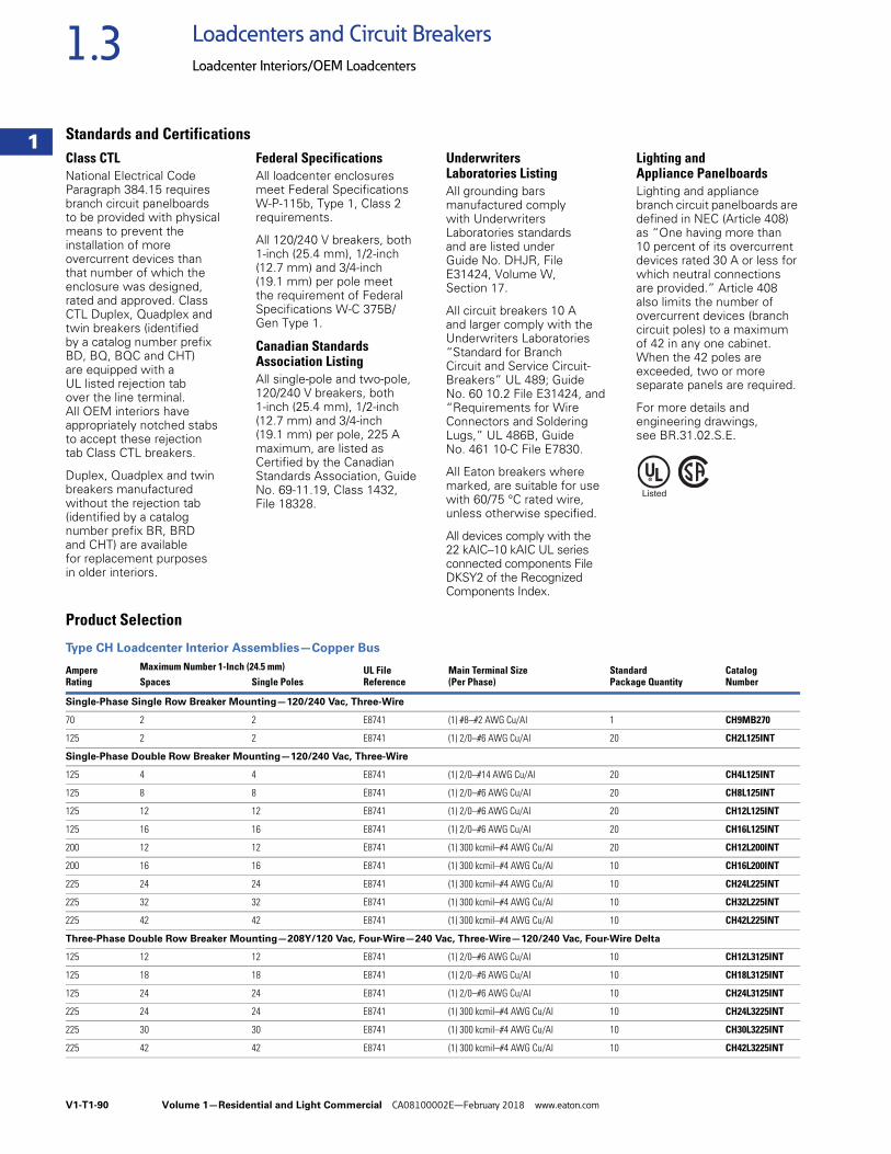
V1-T1-90 Volume 1—Residential and Light Commercial CA08100002E—February 2018 www.eaton.com
1
1
1
1
1
1
1
1
1
1
1
1
1
1
1
1
1
1
1
1
1
1
1
1
1
1
1
1
1
1
1.3 Loadcenters and Circuit Breakers
Loadcenter Interiors/OEM Loadcenters
Standards and CertificationsClass CTLNational Electrical Code Paragraph 384.15 requires branch circuit panelboards to be provided with physical means to prevent the installation of more overcurrent devices than that number of which the enclosure was designed, rated and approved. Class CTL Duplex, Quadplex and twin breakers (identified by a catalog number prefix BD, BQ, BQC and CHT) are equipped with a UL listed rejection tab over the line terminal. All OEM interiors have appropriately notched stabs to accept these rejection tab Class CTL breakers.
Duplex, Quadplex and twin breakers manufactured without the rejection tab (identified by a catalog number prefix BR, BRD and CHT) are available for replacement purposes in older interiors.
Federal SpecificationsAll loadcenter enclosures meet Federal Specifications W-P-115b, Type 1, Class 2 requirements.
All 120/240 V breakers, both 1-inch (25.4 mm), 1/2-inch (12.7 mm) and 3/4-inch (19.1 mm) per pole meet the requirement of Federal Specifications W-C 375B/Gen Type 1.
Canadian Standards Association ListingAll single-pole and two-pole, 120/240 V breakers, both 1-inch (25.4 mm), 1/2-inch (12.7 mm) and 3/4-inch (19.1 mm) per pole, 225 A maximum, are listed as Certified by the Canadian Standards Association, Guide No. 69-11.19, Class 1432, File 18328.
Underwriters Laboratories ListingAll grounding bars manufactured comply with Underwriters Laboratories standards and are listed under Guide No. DHJR, File E31424, Volume W, Section 17.
All circuit breakers 10 A and larger comply with the Underwriters Laboratories “Standard for Branch Circuit and Service Circuit-Breakers” UL 489; Guide No. 60 10.2 File E31424, and “Requirements for Wire Connectors and Soldering Lugs,” UL 486B, Guide No. 461 10-C File E7830.
All Eaton breakers where marked, are suitable for use with 60/75 °C rated wire, unless otherwise specified.
All devices comply with the22 kAIC–10 kAIC UL series connected components File DKSY2 of the Recognized Components Index.
Lighting and Appliance PanelboardsLighting and appliance branch circuit panelboards are defined in NEC (Article 408) as “One having more than 10 percent of its overcurrent devices rated 30 A or less for which neutral connections are provided.” Article 408 also limits the number of overcurrent devices (branch circuit poles) to a maximum of 42 in any one cabinet. When the 42 poles are exceeded, two or more separate panels are required.
For more details and engineering drawings, see BR.31.02.S.E.
Product Selection
Type CH Loadcenter Interior Assemblies—Copper Bus
AmpereRating
Maximum Number 1-Inch (24.5 mm) UL FileReference
Main Terminal Size(Per Phase)
StandardPackage Quantity
Catalog NumberSpaces Single Poles
Single-Phase Single Row Breaker Mounting—120/240 Vac, Three-Wire
70 2 2 E8741 (1) #8–#2 AWG Cu/Al 1 CH9MB270
125 2 2 E8741 (1) 2/0–#6 AWG Cu/Al 20 CH2L125INT
Single-Phase Double Row Breaker Mounting—120/240 Vac, Three-Wire
125 4 4 E8741 (1) 2/0–#14 AWG Cu/Al 20 CH4L125INT
125 8 8 E8741 (1) 2/0–#6 AWG Cu/Al 20 CH8L125INT
125 12 12 E8741 (1) 2/0–#6 AWG Cu/Al 20 CH12L125INT
125 16 16 E8741 (1) 2/0–#6 AWG Cu/Al 20 CH16L125INT
200 12 12 E8741 (1) 300 kcmil–#4 AWG Cu/Al 20 CH12L200INT
200 16 16 E8741 (1) 300 kcmil–#4 AWG Cu/Al 10 CH16L200INT
225 24 24 E8741 (1) 300 kcmil–#4 AWG Cu/Al 10 CH24L225INT
225 32 32 E8741 (1) 300 kcmil–#4 AWG Cu/Al 10 CH32L225INT
225 42 42 E8741 (1) 300 kcmil–#4 AWG Cu/Al 10 CH42L225INT
Three-Phase Double Row Breaker Mounting—208Y/120 Vac, Four-Wire—240 Vac, Three-Wire—120/240 Vac, Four-Wire Delta
125 12 12 E8741 (1) 2/0–#6 AWG Cu/Al 10 CH12L3125INT
125 18 18 E8741 (1) 2/0–#6 AWG Cu/Al 10 CH18L3125INT
125 24 24 E8741 (1) 2/0–#6 AWG Cu/Al 10 CH24L3125INT
225 24 24 E8741 (1) 300 kcmil–#4 AWG Cu/Al 10 CH24L3225INT
225 30 30 E8741 (1) 300 kcmil–#4 AWG Cu/Al 10 CH30L3225INT
225 42 42 E8741 (1) 300 kcmil–#4 AWG Cu/Al 10 CH42L3225INT
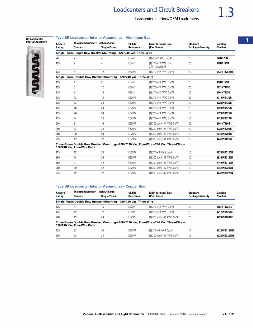
Volume 1—Residential and Light Commercial CA08100002E—February 2018 www.eaton.com V1-T1-91
1
1
1
1
1
1
1
1
1
1
1
1
1
1
1
1
1
1
1
1
1
1
1
1
1
1
1
1
1
1
1.3Loadcenters and Circuit Breakers
Loadcenter Interiors/OEM Loadcenters
Type BR Loadcenter Interior Assemblies—Aluminum Bus
Type BR Loadcenter Interior Assemblies—Copper Bus
AmpereRating
Maximum Number 1-Inch (24.5 mm) UL FileReference
Main Terminal Size(Per Phase)
StandardPackage Quantity
Catalog NumberSpaces Single Poles
Single-Phase Single Row Breaker Mounting—120/240 Vac, Three-Wire
70 2 4 E8741 (1) #8–#2 AWG Cu/Al 20 24INT70B
125 2 4 E8741 (1) 1/0–#14 AWG Cu2/0–12 AWG All
20 24INT125B
125 6 12 E52977 (1) 2/0–#14 AWG Cu/Al 20 612INT125SRB
Single-Phase Double Row Breaker Mounting—120/240 Vac, Three-Wire
125 4 8 E8741 (1) 2/0–#14 AWG Cu/Al 20 48INT125B
125 6 12 E8741 (1) 2/0–#14 AWG Cu/Al 20 612INT125B
125 8 16 E8741 (1) 2/0–#14 AWG Cu/Al 20 816INT125B
125 12 12 E52977 (1) 2/0–#14 AWG Cu/Al 20 1212INT125B
125 12 24 E52977 (1) 2/0–#14 AWG Cu/Al 20 1224INT125B
125 16 24 E52977 (1) 2/0–#14 AWG Cu/Al 20 1624INT125B
125 20 24 E52977 (1) 2/0–#14 AWG Cu/Al 10 2024INT125B
125 24 24 E52977 (1) 2/0–#14 AWG Cu/Al 10 2424INT125B
200 8 16 E52977 (1) 300 kcmil–#1 AWG Cu/Al 20 816INT200B
200 12 24 E52977 (1) 300 kcmil–#1 AWG Cu/Al 20 1224INT200B
200 30 40 E52977 (1) 300 kcmil–#1 AWG Cu/Al 10 3040INT200B
225 42 42 E52977 (1) 300 kcmil–#1 AWG Cu/Al 10 4242INT225B
Three-Phase Double Row Breaker Mounting—208Y/120 Vac, Four-Wire—240 Vac, Three-Wire—120/240 Vac, Four-Wire Delta
125 12 24 E52977 (1) 2/0–#8 AWG Cu/Al 10 1224INT3125B
150 18 36 E52977 (1) 300 kcmil–#2 AWG Cu/Al 10 1836INT3150B
150 24 42 E52977 (1) 300 kcmil–#2 AWG Cu/Al 10 2442INT3150B
200 30 42 E52977 (1) 300 kcmil–#2 AWG Cu/Al 10 3042INT3200B
225 42 42 E52977 (1) 300 kcmil–#2 AWG Cu/Al 10 4242INT3225B
AmpereRating
Maximum Number 1-Inch (24.5 mm) UL FileReference
Main Terminal Size(Per Phase)
StandardPackage Quantity
Catalog NumberSpaces Single Poles
Single-Phase Double Row Breaker Mounting—120/240 Vac, Three-Wire
125 8 16 E5297 (1) 2/0–#14 AWG Cu/Al 20 816INT125BC
125 12 12 E5297 (1) 2/0–#14 AWG Cu/Al 20 1212INT125BC
200 12 24 E5297 (1) 300 kcmil–#1 AWG Cu/Al 20 1224INT200BC
Three-Phase Double Row Breaker Mounting—208Y/120 Vac, Four-Wire—240 Vac, Three-Wire—120/240 Vac, Four-Wire Delta
125 12 24 E52977 (1) 2/0–#8 AWG Cu/Al 10 1224INT3125BC
200 12 24 E52977 (1) 300 kcmil–#2 AWG Cu/Al 10 1224INT3200BC
BR Loadcenter Interior Assembly

V1-T1-92 Volume 1—Residential and Light Commercial CA08100002E—February 2018 www.eaton.com
1
1
1
1
1
1
1
1
1
1
1
1
1
1
1
1
1
1
1
1
1
1
1
1
1
1
1
1
1
1
1.3 Loadcenters and Circuit Breakers
Loadcenter Interiors/OEM Loadcenters
Neutral Assemblies
AmpereRating
ULFileRating
Main Incoming TerminalWire Size Range60 °C or 75 °C
Number of TerminalsStandardPackageQuantity Figure
Dimensions–Inches (mm)
CatalogNumber
#14–4 AWGCu/Al
#6–1/0 AWG Cu#6–2/0 AWG Al
Overall LengthA
MountingB
125 E52977 #6–1/0 AWG Cu#6–2/0 AWG Al
10 — 20 1 5.938 (150.83) 5.400 (137.16) 10NEU125B
125 E52977 #6–1/0 AWG Cu#6–2/0 AWG Al
17 — 20 1 8.388 (213.06) 7.850 (199.40) 17NEU125B
125 E52977 #6–1/0 AWG Cu#6–2/0 AWG Al
20 — 20 1 9.438 (239.73) 8.900 (226.06) 20NEU125B
225 E52977 #1–300 kcmil Cu/Al 24 1 20 2 10.913 (277.19) 10.300 (261.62) 24NEU225B
225 E52977 #1–300 kcmil Cu/Al 35 1 20 2 15.813 (401.65) 15.200 (386.08) 35NEU225B
125 — — 4 2 1 3 2.266 (57.56) 0.594 (15.09) BINA
B
A .269(6.83)
.844(21.44)
2.360(59.94)
CLof Mounting Hole CLof Mounting Hole
1.187(30.15)
1.182(30.02)
B
A
2.000(50.80)
.156(3.96)
.688(17.47)
CLof
MountingHole
.269(6.83)
.344(8.74)
.844(21.44)
2.360(59.94)
1.750(44.45)
2.860(72.64)
.250(6.35)
.182 Diameter(4.62)
.120(3.05)
1.750(44.45)
.750(19.05)
.344(8.74)
CLof Mounting Hole
B
A
Figure 1
Figure 3
Figure 2
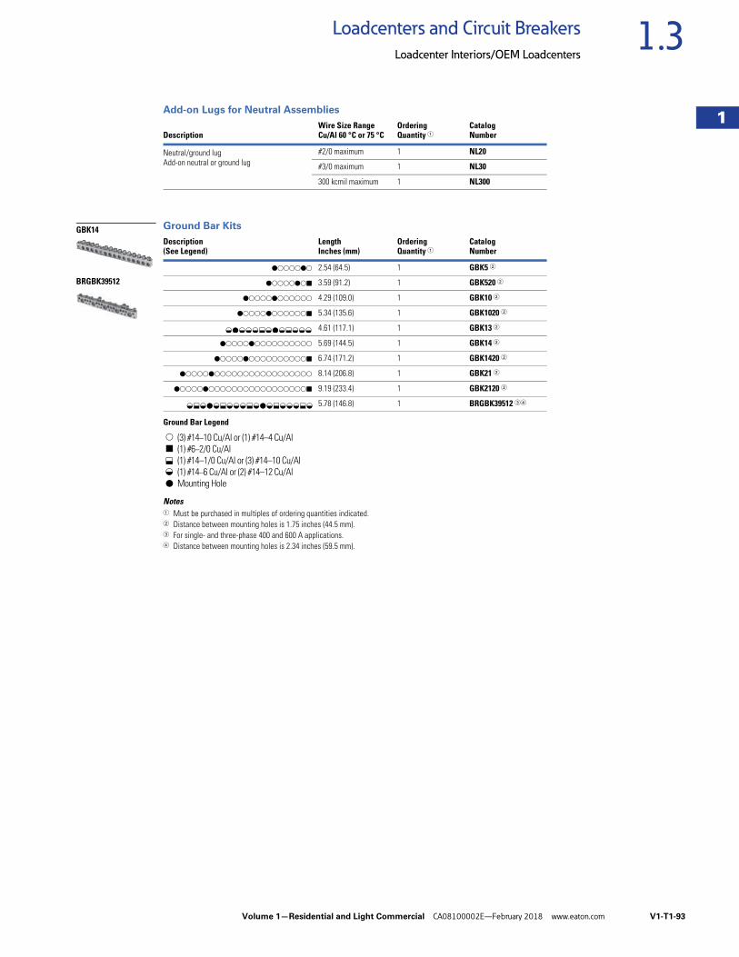
Volume 1—Residential and Light Commercial CA08100002E—February 2018 www.eaton.com V1-T1-93
1
1
1
1
1
1
1
1
1
1
1
1
1
1
1
1
1
1
1
1
1
1
1
1
1
1
1
1
1
1
1.3Loadcenters and Circuit Breakers
Loadcenter Interiors/OEM Loadcenters
Add-on Lugs for Neutral Assemblies
Ground Bar Kits
Ground Bar Legend
Notes1 Must be purchased in multiples of ordering quantities indicated.2 Distance between mounting holes is 1.75 inches (44.5 mm).3 For single- and three-phase 400 and 600 A applications.4 Distance between mounting holes is 2.34 inches (59.5 mm).
DescriptionWire Size RangeCu/Al 60 °C or 75 °C
OrderingQuantity 1
CatalogNumber
Neutral/ground lugAdd-on neutral or ground lug
#2/0 maximum 1 NL20
#3/0 maximum 1 NL30
300 kcmil maximum 1 NL300
Description(See Legend)
LengthInches (mm)
OrderingQuantity 1
CatalogNumber
dssssds 2.54 (64.5) 1 GBK5 2
dssssdsj 3.59 (91.2) 1 GBK520 2
dssssdssssss 4.29 (109.0) 1 GBK10 2
dssssdssssssj 5.34 (135.6) 1 GBK1020 2
4.61 (117.1) 1 GBK13 2
dssssdssssssssss 5.69 (144.5) 1 GBK14 2
dssssdssssssssssj 6.74 (171.2) 1 GBK1420 2
dssssdsssssssssssssssss 8.14 (206.8) 1 GBK21 2
dssssdsssssssssssssssssj 9.19 (233.4) 1 GBK2120 2
5.78 (146.8) 1 BRGBK39512 34
s
j
d
(3) #14–10 Cu/Al or (1) #14–4 Cu/Al(1) #6–2/0 Cu/Al(1) #14–1/0 Cu/Al or (3) #14–10 Cu/Al(1) #14–6 Cu/Al or (2) #14–12 Cu/AlMounting Hole
GBK14
BRGBK39512
f d f f f k f d f k f f f
f k f d f k f f f k f d f k f f f k f
kf
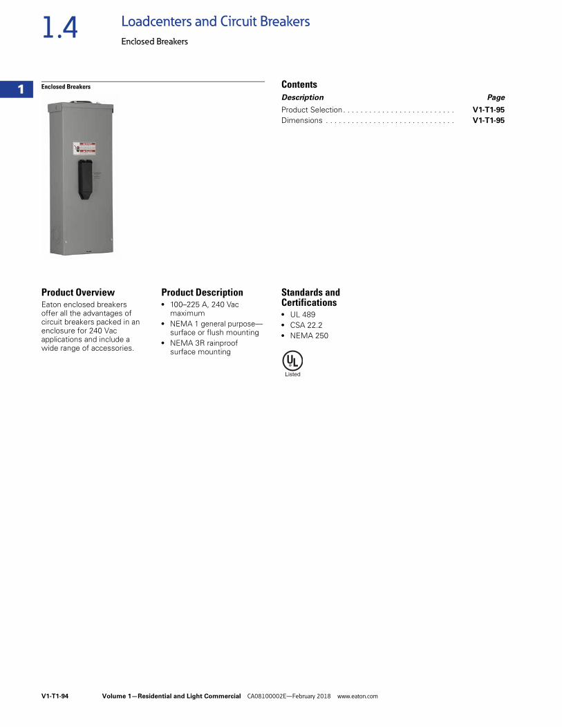
V1-T1-94 Volume 1—Residential and Light Commercial CA08100002E—February 2018 www.eaton.com
1
1
1
1
1
1
1
1
1
1
1
1
1
1
1
1
1
1
1
1
1
1
1
1
1
1
1
1
1
1
1.4 Loadcenters and Circuit Breakers
Enclosed Breakers
Enclosed Breakers ContentsDescription Page
Product Selection. . . . . . . . . . . . . . . . . . . . . . . . . . V1-T1-95
Dimensions . . . . . . . . . . . . . . . . . . . . . . . . . . . . . . V1-T1-95
Product OverviewEaton enclosed breakers offer all the advantages of circuit breakers packed in an enclosure for 240 Vac applications and include a wide range of accessories.
Product Description● 100–225 A, 240 Vac
maximum ● NEMA 1 general purpose—
surface or flush mounting● NEMA 3R rainproof
surface mounting
Standards and Certifications ● UL 489● CSA 22.2● NEMA 250
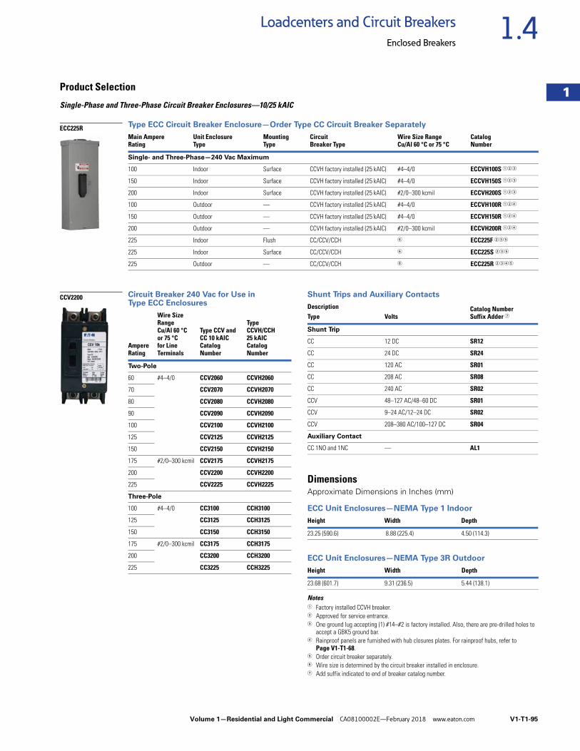
Volume 1—Residential and Light Commercial CA08100002E—February 2018 www.eaton.com V1-T1-95
1
1
1
1
1
1
1
1
1
1
1
1
1
1
1
1
1
1
1
1
1
1
1
1
1
1
1
1
1
1
1.4Loadcenters and Circuit Breakers
Enclosed Breakers
Product Selection
Single-Phase and Three-Phase Circuit Breaker Enclosures—10/25 kAIC
Type ECC Circuit Breaker Enclosure—Order Type CC Circuit Breaker Separately
Circuit Breaker 240 Vac for Use in Type ECC Enclosures
Shunt Trips and Auxiliary Contacts
DimensionsApproximate Dimensions in Inches (mm)
ECC Unit Enclosures—NEMA Type 1 Indoor
ECC Unit Enclosures—NEMA Type 3R Outdoor
Notes1 Factory installed CCVH breaker.2 Approved for service entrance.3 One ground lug accepting (1) #14–#2 is factory installed. Also, there are pre-drilled holes to
accept a GBK5 ground bar.4 Rainproof panels are furnished with hub closures plates. For rainproof hubs, refer to
Page V1-T1-68.5 Order circuit breaker separately.6 Wire size is determined by the circuit breaker installed in enclosure.7 Add suffix indicated to end of breaker catalog number.
Main AmpereRating
Unit EnclosureType
Mounting Type
Circuit Breaker Type
Wire Size RangeCu/Al 60 °C or 75 °C
CatalogNumber
Single- and Three-Phase—240 Vac Maximum
100 Indoor Surface CCVH factory installed (25 kAIC) #4–4/0 ECCVH100S 123
150 Indoor Surface CCVH factory installed (25 kAIC) #4–4/0 ECCVH150S 123
200 Indoor Surface CCVH factory installed (25 kAIC) #2/0–300 kcmil ECCVH200S 123
100 Outdoor — CCVH factory installed (25 kAIC) #4–4/0 ECCVH100R 124
150 Outdoor — CCVH factory installed (25 kAIC) #4–4/0 ECCVH150R 124
200 Outdoor — CCVH factory installed (25 kAIC) #2/0–300 kcmil ECCVH200R 124
225 Indoor Flush CC/CCV/CCH 6 ECC225F 235
225 Indoor Surface CC/CCV/CCH 6 ECC225S 235
225 Outdoor — CC/CCV/CCH 6 ECC225R 2345
ECC225R
AmpereRating
Wire Size RangeCu/Al 60 °C or 75 °C for LineTerminals
Type CCV and CC 10 kAICCatalog Number
Type CCVH/CCH 25 kAIC Catalog Number
Two-Pole
60 #4–4/0 CCV2060 CCVH2060
70 CCV2070 CCVH2070
80 CCV2080 CCVH2080
90 CCV2090 CCVH2090
100 CCV2100 CCVH2100
125 CCV2125 CCVH2125
150 CCV2150 CCVH2150
175 #2/0–300 kcmil CCV2175 CCVH2175
200 CCV2200 CCVH2200
225 CCV2225 CCVH2225
Three-Pole
100 #4–4/0 CC3100 CCH3100
125 CC3125 CCH3125
150 CC3150 CCH3150
175 #2/0–300 kcmil CC3175 CCH3175
200 CC3200 CCH3200
225 CC3225 CCH3225
CCV2200Description Catalog Number
Suffix Adder 7Type Volts
Shunt Trip
CC 12 DC SR12
CC 24 DC SR24
CC 120 AC SR01
CC 208 AC SR08
CC 240 AC SR02
CCV 48–127 AC/48–60 DC SR01
CCV 9–24 AC/12–24 DC SR02
CCV 208–380 AC/100–127 DC SR04
Auxiliary Contact
CC 1NO and 1NC — AL1
Height Width Depth
23.25 (590.6) 8.88 (225.4) 4.50 (114.3)
Height Width Depth
23.68 (601.7) 9.31 (236.5) 5.44 (138.1)
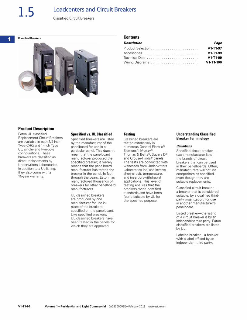
V1-T1-96 Volume 1—Residential and Light Commercial CA08100002E—February 2018 www.eaton.com
1
1
1
1
1
1
1
1
1
1
1
1
1
1
1
1
1
1
1
1
1
1
1
1
1
1
1
1
1
1
1.5 Loadcenters and Circuit Breakers
Classified Circuit Breakers
Classified Breakers ContentsDescription Page
Product Selection. . . . . . . . . . . . . . . . . . . . . . . . . . V1-T1-97
Accessories . . . . . . . . . . . . . . . . . . . . . . . . . . . . . . V1-T1-99
Technical Data . . . . . . . . . . . . . . . . . . . . . . . . . . . . V1-T1-99
Wiring Diagrams . . . . . . . . . . . . . . . . . . . . . . . . . . V1-T1-100
Product DescriptionEaton UL classified Replacement Circuit Breakers are available in both 3/4-inch Type CHQ and 1-inch Type CL, single- and two-pole configurations. These breakers are classified as direct replacements by Underwriters Laboratories. In addition to a UL listing, they also come with a 15-year warranty.
Specified vs. UL ClassifiedSpecified breakers are listed by the manufacturer of the panelboard for use in a particular panel. This doesn’t mean that the panelboard manufacturer produced the specified breaker; it merely means that the panelboard manufacturer has tested the breaker in the panel. In fact, through the years, Eaton has manufactured thousands of breakers for other panelboard manufacturers.
UL classified breakers are produced by one manufacturer for use in place of the breakers specified on the panelboard. Like specified breakers, UL classified breakers have been tested in the panels for which they are approved.
TestingClassified breakers are tested extensively in numerous General Electric®, Siemens®, Murray®, Thomas & Betts®, Square D®, and Crouse-Hinds® panels. The tests are conducted with witnesses from Underwriters Laboratories Inc. and involve short-circuit, temperature, and insertion/withdrawal applications. This level of testing ensures that the breakers meet identified standards and have been found suitable by UL for the specified purpose.
Understanding Classified Breaker Terminology
DefinitionsSpecified circuit breaker—each manufacturer lists the brands of circuit breakers that can be usedin their panelboards. Often, manufacturers will not list competitors as specified, even though they are suitable replacements.
Classified circuit breaker—a breaker that is considered suitable, by a qualified third-party organization, for use in another manufacturer’s panelboard.
Listed breaker—the listingof a circuit breaker is by an independent third party. Eaton classified breakers are listed by UL.
Labeled breaker—a breaker with a label affixed by an independent third party.
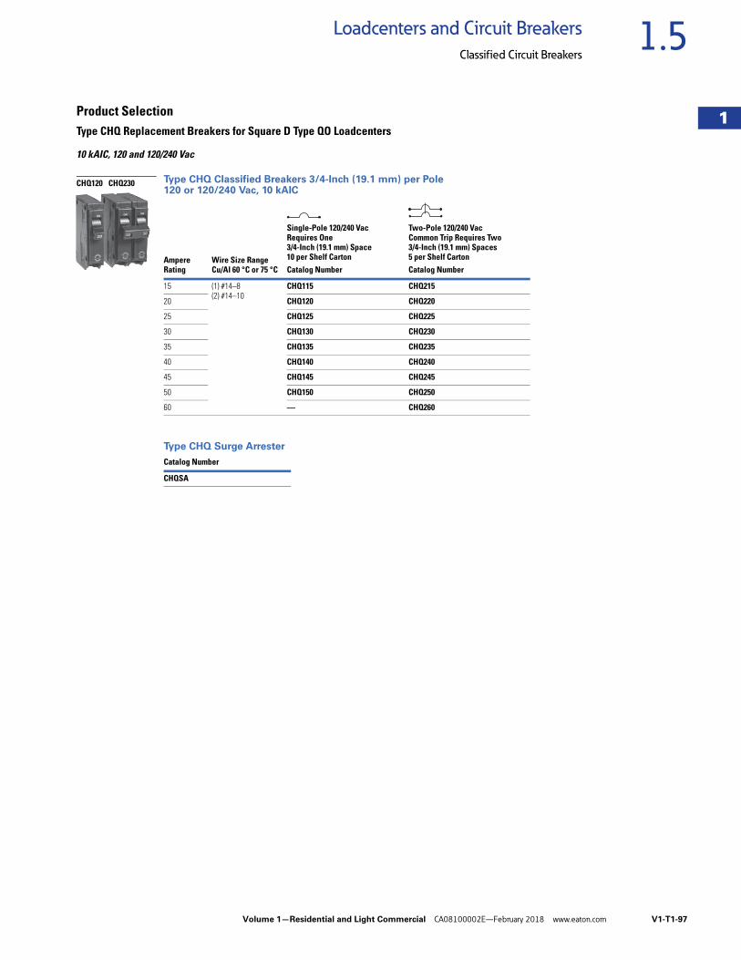
Volume 1—Residential and Light Commercial CA08100002E—February 2018 www.eaton.com V1-T1-97
1
1
1
1
1
1
1
1
1
1
1
1
1
1
1
1
1
1
1
1
1
1
1
1
1
1
1
1
1
1
1.5Loadcenters and Circuit Breakers
Classified Circuit Breakers
Product SelectionType CHQ Replacement Breakers for Square D Type QO Loadcenters
10 kAIC, 120 and 120/240 Vac
Type CHQ Classified Breakers 3/4-Inch (19.1 mm) per Pole 120 or 120/240 Vac, 10 kAIC
Type CHQ Surge Arrester
AmpereRating
Wire Size RangeCu/Al 60 °C or 75 °C
Single-Pole 120/240 VacRequires One 3/4-Inch (19.1 mm) Space10 per Shelf Carton
Two-Pole 120/240 VacCommon Trip Requires Two 3/4-Inch (19.1 mm) Spaces5 per Shelf Carton
Catalog Number Catalog Number
15 (1) #14–8(2) #14–10
CHQ115 CHQ215
20 CHQ120 CHQ220
25 CHQ125 CHQ225
30 CHQ130 CHQ230
35 CHQ135 CHQ235
40 CHQ140 CHQ240
45 CHQ145 CHQ245
50 CHQ150 CHQ250
60 — CHQ260
Catalog Number
CHQSA
CHQ120 CHQ230
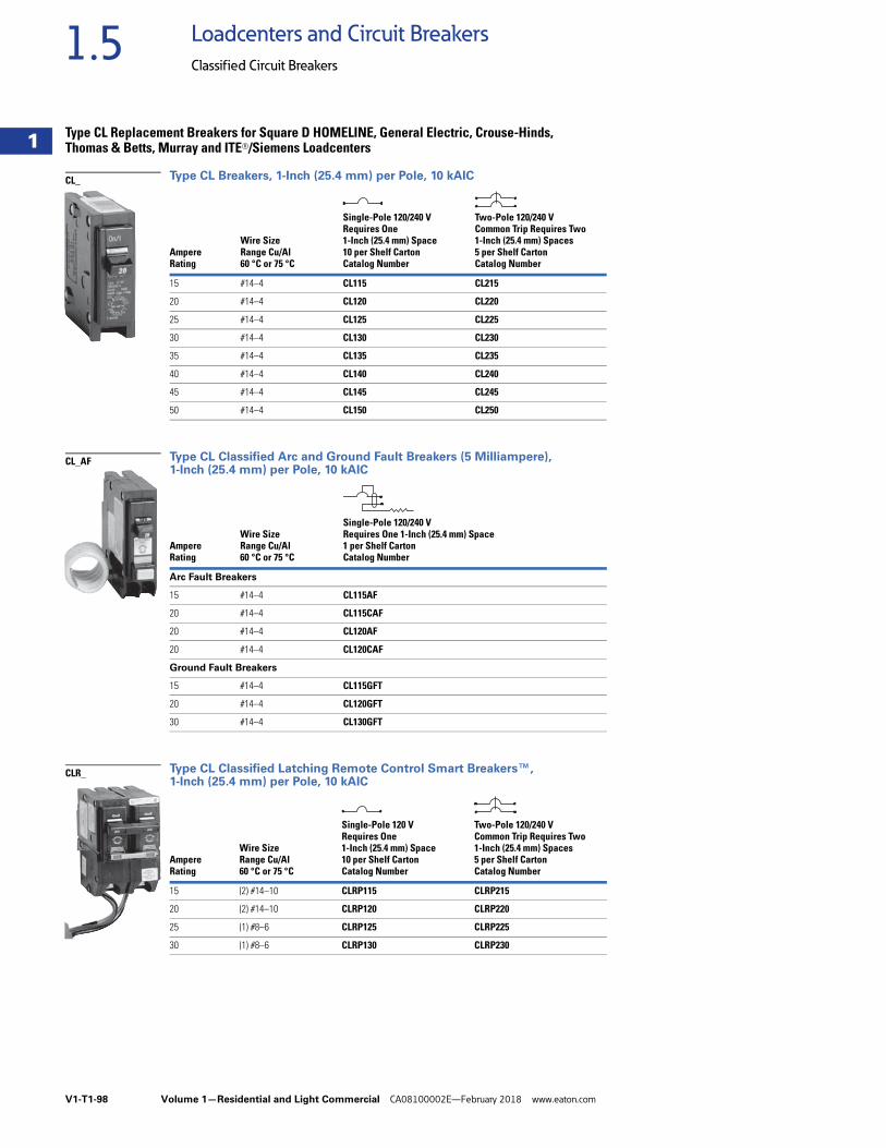
V1-T1-98 Volume 1—Residential and Light Commercial CA08100002E—February 2018 www.eaton.com
1
1
1
1
1
1
1
1
1
1
1
1
1
1
1
1
1
1
1
1
1
1
1
1
1
1
1
1
1
1
1.5 Loadcenters and Circuit Breakers
Classified Circuit Breakers
Type CL Replacement Breakers for Square D HOMELINE, General Electric, Crouse-Hinds, Thomas & Betts, Murray and ITE®/Siemens Loadcenters
Type CL Breakers, 1-Inch (25.4 mm) per Pole, 10 kAIC
Type CL Classified Arc and Ground Fault Breakers (5 Milliampere), 1-Inch (25.4 mm) per Pole, 10 kAIC
Type CL Classified Latching Remote Control Smart Breakers™, 1-Inch (25.4 mm) per Pole, 10 kAIC
AmpereRating
Wire SizeRange Cu/Al60 °C or 75 °C
Single-Pole 120/240 VRequires One1-Inch (25.4 mm) Space10 per Shelf CartonCatalog Number
Two-Pole 120/240 VCommon Trip Requires Two1-Inch (25.4 mm) Spaces5 per Shelf CartonCatalog Number
15 #14–4 CL115 CL215
20 #14–4 CL120 CL220
25 #14–4 CL125 CL225
30 #14–4 CL130 CL230
35 #14–4 CL135 CL235
40 #14–4 CL140 CL240
45 #14–4 CL145 CL245
50 #14–4 CL150 CL250
AmpereRating
Wire SizeRange Cu/Al60 °C or 75 °C
Single-Pole 120/240 VRequires One 1-Inch (25.4 mm) Space1 per Shelf CartonCatalog Number
Arc Fault Breakers
15 #14–4 CL115AF
20 #14–4 CL115CAF
20 #14–4 CL120AF
20 #14–4 CL120CAF
Ground Fault Breakers
15 #14–4 CL115GFT
20 #14–4 CL120GFT
30 #14–4 CL130GFT
AmpereRating
Wire SizeRange Cu/Al60 °C or 75 °C
Single-Pole 120 VRequires One1-Inch (25.4 mm) Space10 per Shelf CartonCatalog Number
Two-Pole 120/240 VCommon Trip Requires Two1-Inch (25.4 mm) Spaces5 per Shelf CartonCatalog Number
15 (2) #14–10 CLRP115 CLRP215
20 (2) #14–10 CLRP120 CLRP220
25 (1) #8–6 CLRP125 CLRP225
30 (1) #8–6 CLRP130 CLRP230
CL_
CL_AF
CLR_
Volume 1—Residential and Light Commercial CA08100002E—February 2018 www.eaton.com V1-T1-99
1
1
1
1
1
1
1
1
1
1
1
1
1
1
1
1
1
1
1
1
1
1
1
1
1
1
1
1
1
1
1.5Loadcenters and Circuit Breakers
Classified Circuit Breakers
AccessoriesCHQ Breaker Accessories
Technical DataArc Fault Application NotesAn arc fault circuit interrupter is a device intended to provide protection from the effects of arc faults by recognizing characteristics unique to arcing and by functioning to de-energize the circuit when the arc fault is detected. As of January 1, 2002, the National Electrical Code (NEC) requires all branch circuits that supply 125 V, single-phase, 15 and 20 A receptacle outlets installed in dwelling unit bedrooms shall be protected by an arc fault circuit interrupter(s). This includes ceiling lighting (recessed, ceiling fans, etc.) as well as smoke detectors and all other bedroom outlets. The 2005 NEC introduced the application of the Combination Type AFCI for bedroom circuits required as of January 1, 2008. The 2008 NEC expands this application to other living areas.
Ground Fault Application NotesSingle-pole GFTCBs are designed for use in two-wire, 120 Vac circuits. Drawing on Page V1-T1-100 shows a typical wiring configuration.
Two-pole GFTCBs are designed for use in three-wire, 120/240 Vac circuits, 120 Vac multiwire circuits employing common, neutral and two-wire, 240 Vac circuits obtained from a 120/240 Vac source.
Drawings on Page V1-T1-100 illustrate typical wiring configurations for 120/240 Vac multiwire circuits.
Drawing on Page V1-T1-100 depicts a 240 Vac, two-wire circuit. Note the “panel neutral” conductor connects to the neutral bar, even though the neutral is not included in the load circuit. This connection is necessary to supply a 120 Vac power source to the ground fault sensing circuit.
The figures are shown with a 120/240 Vac, single-phase, three-wire power source, ut are also applicable to a 120/208 Vac, three-phase, four-wire power supply. For all figures, the electrical operation of the GFTCB is not affected by the equipment ground.
DescriptionCatalogNumber
Breaker handle lock CHLO
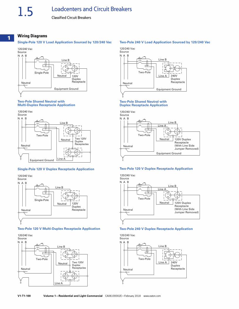
V1-T1-100 Volume 1—Residential and Light Commercial CA08100002E—February 2018 www.eaton.com
1
1
1
1
1
1
1
1
1
1
1
1
1
1
1
1
1
1
1
1
1
1
1
1
1
1
1
1
1
1
1.5 Loadcenters and Circuit Breakers
Classified Circuit Breakers
Wiring DiagramsSingle-Pole 120 V Load Application Sourced by 120/240 Vac
Two-Pole Shared Neutral with Multi-Duplex Receptacle Application
Single-Pole 120 V Duplex Receptacle Application
Two-Pole 120 V Multi-Duplex Receptacle Application
Two-Pole 240 V Load Application Sourced by 120/240 Vac
Two-Pole Shared Neutral with Duplex Receptacle Application
Two-Pole 120 V Duplex Receptacle Application
Two-Pole 240 V Duplex Receptacle Application
N A B
120/240 VacSource
120VDuplexReceptacle
Single-Pole
Line B
Neutral
Neutral
Equipment Ground
N A B
120/240 VacSource
Two 120VDuplexReceptacles
Two-Pole
Line B
Line A
Neutral
Neutral
Equipment Ground
N A B
120/240 VacSource
120VDuplexReceptacle
Single-Pole
Line B
Neutral
Neutral
N A B
120/240 VacSource
Two 120VDuplexReceptacles
Two-Pole
Line B
Line A
Neutral
Neutral
Line B
N A B
120/240 VacSource
Line A 240VDuplexReceptacle
Two-Pole
Neutral
Equipment Ground
N A B
120/240 VacSource
Line A
120V DuplexReceptacle(With Line SideJumper Removed)
Two-Pole
Line B
Neutral
Neutral
Equipment Ground
N A B
120/240 VacSource
Line A
120V DuplexReceptacle(With Line SideJumper Removed)
Two-Pole
Line B
Neutral
Neutral
Line B
N A B
120/240 VacSource
Line A 240VDuplexReceptacle
Two-Pole
Neutral