Determination of the Thermal Resistance of Pipe Insulation ...

Copyright GRL Engineers, Inc. 2016 Page 1
LOAD TRANSFER AND UNIT SHAFT RESISTANCE DETERMINATION
Driven piles, drilled shafts, and continuous flight auger (CFA) or augered cast-in-place (ACIP) piles are often
instrumented with strain gages along their embedded length to evaluate how the applied load is transferred to
the surrounding soil and/or rock materials during a static load test.
In deep foundations constructed with concrete, vibrating-wire or resistance “sister bar” strain gage assemblies
are incorporated in the deep foundation element prior to concrete placement. Each sister bar assembly consists
of a strain gage mounted along the axis of a length of rebar as illustrated in Figure 1.
In closed end pipe piles, Monotube® piles, and TapertubeTM piles that are driven and then filled with concrete,
sister bar strain gage assemblies are typically attached to a centering pipe or rebar that is inserted into the pile
prior to concrete placement as shown in Figure 2.
Figure 1. Vibrating Wire Strain Gage Sister Bars Attached to Reinforcing Cage.
Figure 2. Sister Bar Mounted Strain Gages on Centering Rod. Vibrating Wire Strain Gage
(on left) and Resistance Strain Gage and Accelerometer (on right).

Copyright GRL Engineers, Inc. 2016 Page 2
Vibrating wire and resistance strain gages are shown mounted directly to an open end steel pipe pile in Figure
3 and on a steel H-pile in Figure 4. Channels are then welded over the strain gages and their cables for
protection during driving.
Figure 3. Anchor Block Mounted Vibrating Wire Strain Gage (left), Bolt-On Resistance Strain Gage
(center), and Accelerometer (right) with Protective Channel Cover (far right) to be added.
Figure 4. Anchor Block Mounted Vibrating Wire Strain Gage, with Protective Channel Cover Over Gage
Location to be Added Following Pile Splicing.

Copyright GRL Engineers, Inc. 2016 Page 3
A 48-inch diameter open end pipe pile in the process of being instrumented is shown in Figure 5. The same pile
is again shown in Figure 6 once the instrumentation is complete and the protective covers have been added.
Figure 5. Attaching Instrumentation, Wiring, and Protective Cover Plate on Open End Pipe Pile.
Figure 6. Completely Instrumented Open End Pipe Pile Ready for Driving.

Copyright GRL Engineers, Inc. 2016 Page 4
Strain gage data is used in conjunction with a deep foundation’s cross-sectional area and elastic modulus to
determine the axial compression load in the deep foundation element at each strain gage elevation. The resulting
load transfer profile, depicted in Figure 7, provides information on the shaft resistance distribution and the shaft
and toe resistance magnitudes.
Figure 7. Load Transfer Profiles Under Axial Compression Load.
Copyright GRL Engineers, Inc. 2016 Page 5
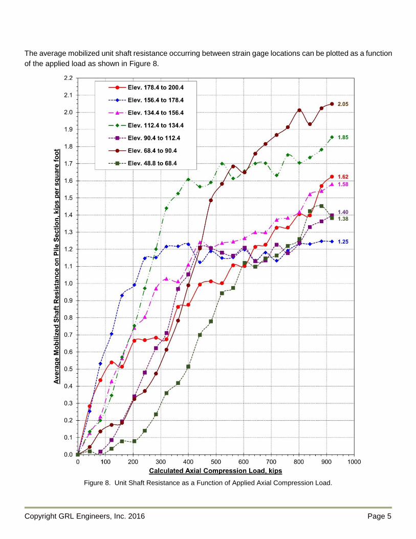
The average mobilized unit shaft resistance occurring between strain gage locations can be plotted as a function
of the applied load as shown in Figure 8.
Figure 8. Unit Shaft Resistance as a Function of Applied Axial Compression Load.

Copyright GRL Engineers, Inc. 2016 Page 6
The average mobilized unit shaft resistance occurring between strain gage locations at the maximum applied
load can then be plotted versus elevation or depth as illustrated in Figure 9. These results can be used to
confirm, correlate, calibrate, and refine static capacity analyses or dynamic testing results. Correlation with soil
properties and dynamic test results enhances the value and benefit gained from a static load test by allowing
extrapolation of the test results across the construction site.
Figure 9. Unit Shaft Resistance Versus Elevation at Maximum Applied Load.