Load Sharing in Two-Pass Lining Systems for NATM Tunnels · Load Sharing in Two-Pass Lining Systems...
14
1178 LOAD SHARING IN TWO-PASS LINING SYSTEMS FOR NATM TUNNELS Yiming Sun ■ Jacobs Associates Mike McRae ■ Jacobs Associates Jan Van Greunen ■ Jacobs Associates ABSTRACT Generally, two-pass lining systems are used for transportation tunnels constructed using the New Austrian Tunneling Method (NATM). The initial lining can support a sig- nificant portion of the long-term ground loads and thus reduce the design loads on the permanent lining. This load-sharing phenomenon has traditionally been neglected, but considering load sharing in design can result in significant cost savings. This paper discusses the basic principles of load sharing in two-pass lining systems and proposes a rational method for design. Practical application of the load sharing design approach in a NATM tunnel project, the Caldecott Fourth Bore, is presented. INTRODUCTION Most transportation tunnels constructed using the New Austrian Tunneling Method (NATM) or Sequential Excavation Method (SEM) use a two-pass lining system. The initial lining typically consists of fiber reinforced or plain shotcrete, often augmented by some form of rock reinforcement (e.g., rock dowels), while the secondary lining (also called final or permanent lining) consists of either shotcrete or cast-in-place (CIP) reinforced concrete. Depending on ground and hydrogeologic conditions, a spray-on or sheet waterproofing membrane is often installed between the initial and secondary linings to ensure a watertight tunnel. The initial lining and rock reinforcement are typically designed to carry the ground loads, control the ground deformations during tunnel construction, and provide a safe work environment. The secondary lining is designed to support the long-term ground loads, hydrostatic loads where applicable, and any additional loads resulting from fin- ishes or anchored equipment. The secondary lining also provides a permanent lining for fire protection and accommodates seismic deformations if the tunnel is located in a seismically active region. With this design approach, the installed initial lining is not considered to be a component of the long-term load-carrying lining system. However, the initial lining does have the capacity to support a significant portion of the long-term ground loads during the design life of a tunnel. Neglecting the long-term load-carrying capacity of the initial lining results, in some cases, in an overly conservative design for the secondary lining. In order to achieve a cost-effective design, the concept of load sharing between the initial and secondary linings in the design of the secondary lining has been gaining increased acceptance by tunnel designers in recent years. This load- sharing approach has been applied to the design of many NATM tunnels worldwide. This paper discusses the basic mechanism of load sharing in two-pass lining sys- tems and proposes a rational approach for design. The practical application of the load-sharing design approach in a NATM tunnel project, the Caldecott Fourth Bore, is also presented.
Transcript of Load Sharing in Two-Pass Lining Systems for NATM Tunnels · Load Sharing in Two-Pass Lining Systems...
1178
LOAD SHARING IN TWO-PASS LINING SYSTEMS FOR NATM TUNNELS
Yiming Sun ■ Jacobs Associates
Mike McRae ■ Jacobs Associates
Jan Van Greunen ■ Jacobs Associates
ABSTRACTGenerally, two-pass lining systems are used for transportation tunnels constructed using the New Austrian Tunneling Method (NATM). The initial lining can support a sig-nificant portion of the long-term ground loads and thus reduce the design loads on the permanent lining. This load-sharing phenomenon has traditionally been neglected, but considering load sharing in design can result in significant cost savings. This paper discusses the basic principles of load sharing in two-pass lining systems and proposes a rational method for design. Practical application of the load sharing design approach in a NATM tunnel project, the Caldecott Fourth Bore, is presented.
INTRODUCTIONMost transportation tunnels constructed using the New Austrian Tunneling Method (NATM) or Sequential Excavation Method (SEM) use a two-pass lining system. The initial lining typically consists of fiber reinforced or plain shotcrete, often augmented by some form of rock reinforcement (e.g., rock dowels), while the secondary lining (also called final or permanent lining) consists of either shotcrete or cast-in-place (CIP) reinforced concrete. Depending on ground and hydrogeologic conditions, a spray-on or sheet waterproofing membrane is often installed between the initial and secondary linings to ensure a watertight tunnel.
The initial lining and rock reinforcement are typically designed to carry the ground loads, control the ground deformations during tunnel construction, and provide a safe work environment. The secondary lining is designed to support the long-term ground loads, hydrostatic loads where applicable, and any additional loads resulting from fin-ishes or anchored equipment. The secondary lining also provides a permanent lining for fire protection and accommodates seismic deformations if the tunnel is located in a seismically active region. With this design approach, the installed initial lining is not considered to be a component of the long-term load-carrying lining system. However, the initial lining does have the capacity to support a significant portion of the long-term ground loads during the design life of a tunnel. Neglecting the long-term load-carrying capacity of the initial lining results, in some cases, in an overly conservative design for the secondary lining. In order to achieve a cost-effective design, the concept of load sharing between the initial and secondary linings in the design of the secondary lining has been gaining increased acceptance by tunnel designers in recent years. This load-sharing approach has been applied to the design of many NATM tunnels worldwide.
This paper discusses the basic mechanism of load sharing in two-pass lining sys-tems and proposes a rational approach for design. The practical application of the load-sharing design approach in a NATM tunnel project, the Caldecott Fourth Bore, is also presented.
Load Sharing in Two-Pass Lining Systems 1179
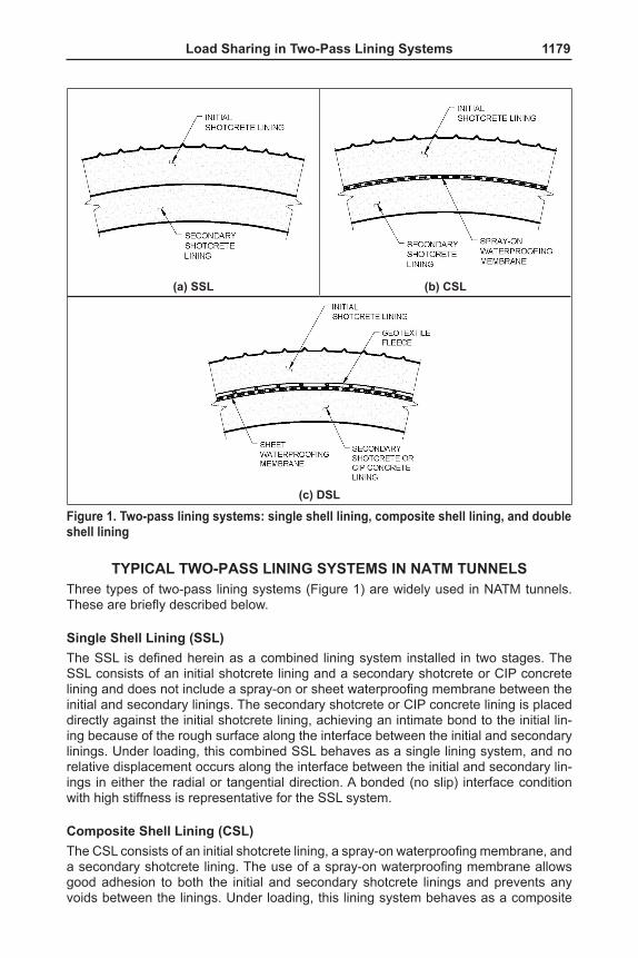
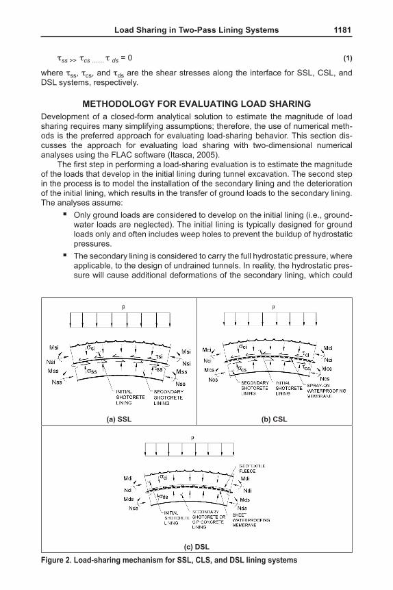
TYPICAL TWO-PASS LINING SYSTEMS IN NATM TUNNELSThree types of two-pass lining systems (Figure 1) are widely used in NATM tunnels. These are briefly described below.
Single Shell Lining (SSL)The SSL is defined herein as a combined lining system installed in two stages. The SSL consists of an initial shotcrete lining and a secondary shotcrete or CIP concrete lining and does not include a spray-on or sheet waterproofing membrane between the initial and secondary linings. The secondary shotcrete or CIP concrete lining is placed directly against the initial shotcrete lining, achieving an intimate bond to the initial lin-ing because of the rough surface along the interface between the initial and secondary linings. Under loading, this combined SSL behaves as a single lining system, and no relative displacement occurs along the interface between the initial and secondary lin-ings in either the radial or tangential direction. A bonded (no slip) interface condition with high stiffness is representative for the SSL system.
Composite Shell Lining (CSL)The CSL consists of an initial shotcrete lining, a spray-on waterproofing membrane, and a secondary shotcrete lining. The use of a spray-on waterproofing membrane allows good adhesion to both the initial and secondary shotcrete linings and prevents any voids between the linings. Under loading, this lining system behaves as a composite
(a) SSL (b) CSL
(c) DSL
Figure 1. Two-pass lining systems: single shell lining, composite shell lining, and double shell lining
1180 SEM/NATM
shell lining system. Relative displacements in both the radial and tangential directions between the initial and secondary linings may occur as a result of deformations of the spray-on waterproofing membrane. These relative displacements depend on the thick-ness and stiffness of the spray-on waterproofing membrane. A bonded interface condi-tion with low stiffness is considered a reasonable representation for the CSL system.
Double Shell Lining (DSL)The DSL consists of an initial shotcrete lining, a sheet waterproofing membrane, and a secondary shotcrete or CIP concrete lining. The sheet waterproofing membrane is not bonded to either the initial shotcrete lining or the secondary shotcrete or CIP concrete lining. Voids along the interface may still exist, even though contact grouting is usually performed to fill these voids. Under loading, the initial and secondary linings behave as two separate shells and relative displacements may occur in both the radial and tangential directions along the interface, especially in the tangential (shear) direction. A full slip interface condition is usually assumed for the DSL system.
DISCUSSION OF THE LOAD-SHARING MECHANISMThe initial shotcrete lining for a NATM tunnel is designed and installed as temporary support for carrying ground loads induced by tunnel excavation. The initial shotcrete lining may degrade over time, particularly in aggressive environments due to the cor-rosion of steel reinforcement subject to high chloride conditions or deterioration of the shotcrete because of the presence of sulfates in the ground or groundwater (Nordstrom, 2005; Santhanam et al., 2003). This degradation of the initial shotcrete lining causes redistributions of stresses and strains or loads in the lining and adjacent ground, and possibly additional deformation of the lining. As a result of the degradation and addi-tional deformation of the initial lining, the loads originally developed in the initial lining will redistribute to both the adjacent ground and secondary lining over the long term.
The magnitude of load transferred from the initial lining to the secondary lining, also called the load sharing, depends on many factors, including:
■ Available bond and normal and shear stiffness of the interface ■ Ground conditions such as rock mass strength/stiffness ■ Relative stiffness between the initial and secondary linings ■ In situ stress conditions such as the ratio of horizontal-to-vertical stresses (Ko) ■ Tunnel shape (e.g., circular and horse-shoe shaped).
As discussed above, there are two interface conditions, bonded and full slip, which are associated with the three types of lining systems: SSL, CSL, and DSL. The SSL approach assumes a fully bonded interface, while the DSL approach assumes a full slip interface. The CSL approach assumes a bonded interface with low shear stiffness, with the absolute stiffness depending on the thickness and properties of the spray-on waterproofing membrane.
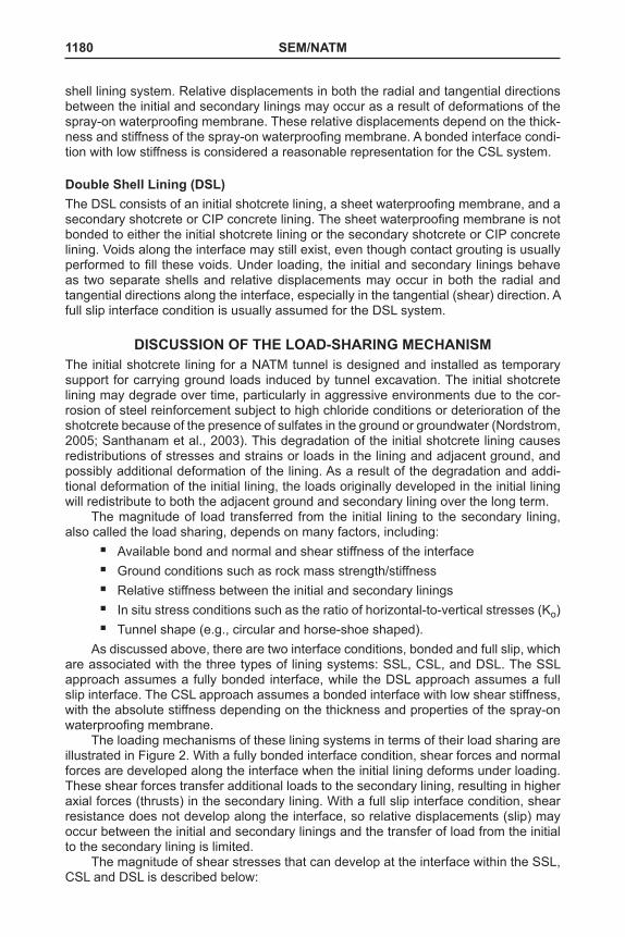
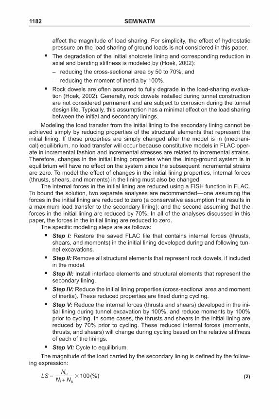
The loading mechanisms of these lining systems in terms of their load sharing are illustrated in Figure 2. With a fully bonded interface condition, shear forces and normal forces are developed along the interface when the initial lining deforms under loading. These shear forces transfer additional loads to the secondary lining, resulting in higher axial forces (thrusts) in the secondary lining. With a full slip interface condition, shear resistance does not develop along the interface, so relative displacements (slip) may occur between the initial and secondary linings and the transfer of load from the initial to the secondary lining is limited.
The magnitude of shear stresses that can develop at the interface within the SSL, CSL and DSL is described below:
Load Sharing in Two-Pass Lining Systems 1181
tss >> tcs …… t ds = 0 (1)
where tss, tcs, and tds are the shear stresses along the interface for SSL, CSL, and DSL systems, respectively.
METHODOLOGY FOR EVALUATING LOAD SHARINGDevelopment of a closed-form analytical solution to estimate the magnitude of load sharing requires many simplifying assumptions; therefore, the use of numerical meth-ods is the preferred approach for evaluating load-sharing behavior. This section dis-cusses the approach for evaluating load sharing with two-dimensional numerical analyses using the FLAC software (Itasca, 2005).
The first step in performing a load-sharing evaluation is to estimate the magnitude of the loads that develop in the initial lining during tunnel excavation. The second step in the process is to model the installation of the secondary lining and the deterioration of the initial lining, which results in the transfer of ground loads to the secondary lining. The analyses assume:
■ Only ground loads are considered to develop on the initial lining (i.e., ground-water loads are neglected). The initial lining is typically designed for ground loads only and often includes weep holes to prevent the buildup of hydrostatic pressures.
■ The secondary lining is considered to carry the full hydrostatic pressure, where applicable, to the design of undrained tunnels. In reality, the hydrostatic pres-sure will cause additional deformations of the secondary lining, which could
(a) SSL (b) CSL
(c) DSL
Figure 2. Load-sharing mechanism for SSL, CLS, and DSL lining systems
1182 SEM/NATM
affect the magnitude of load sharing. For simplicity, the effect of hydrostatic pressure on the load sharing of ground loads is not considered in this paper.
■ The degradation of the initial shotcrete lining and corresponding reduction in axial and bending stiffness is modeled by (Hoek, 2002):
– reducing the cross-sectional area by 50 to 70%, and – reducing the moment of inertia by 100%.
■ Rock dowels are often assumed to fully degrade in the load-sharing evalua-tion (Hoek, 2002). Generally, rock dowels installed during tunnel construction are not considered permanent and are subject to corrosion during the tunnel design life. Typically, this assumption has a minimal effect on the load sharing between the initial and secondary linings.
Modeling the load transfer from the initial lining to the secondary lining cannot be achieved simply by reducing properties of the structural elements that represent the initial lining. If these properties are simply changed after the model is in (mechani-cal) equilibrium, no load transfer will occur because constitutive models in FLAC oper-ate in incremental fashion and incremental stresses are related to incremental strains. Therefore, changes in the initial lining properties when the lining-ground system is in equilibrium will have no effect on the system since the subsequent incremental strains are zero. To model the effect of changes in the initial lining properties, internal forces (thrusts, shears, and moments) in the lining must also be changed.
The internal forces in the initial lining are reduced using a FISH function in FLAC. To bound the solution, two separate analyses are recommended—one assuming the forces in the initial lining are reduced to zero (a conservative assumption that results in a maximum load transfer to the secondary lining); and the second assuming that the forces in the initial lining are reduced by 70%. In all of the analyses discussed in this paper, the forces in the initial lining are reduced to zero.
The specific modeling steps are as follows: ■ Step I: Restore the saved FLAC file that contains internal forces (thrusts,
shears, and moments) in the initial lining developed during and following tun-nel excavations.
■ Step II: Remove all structural elements that represent rock dowels, if included in the model.
■ Step III: Install interface elements and structural elements that represent the secondary lining.
■ Step IV: Reduce the initial lining properties (cross-sectional area and moment of inertia). These reduced properties are fixed during cycling.
■ Step V: Reduce the internal forces (thrusts and shears) developed in the ini-tial lining during tunnel excavation by 100%, and reduce moments by 100% prior to cycling. In some cases, the thrusts and shears in the initial lining are reduced by 70% prior to cycling. These reduced internal forces (moments, thrusts, and shears) will change during cycling based on the relative stiffness of each of the linings.
■ Step VI: Cycle to equilibrium.The magnitude of the load carried by the secondary lining is defined by the follow-
ing expression:
100(%)LS N NNi s
s #=+
(2)
Load Sharing in Two-Pass Lining Systems 1183
where LS is the magnitude of load sharing in percent; Ni is the axial force developed in the initial lining during the load-sharing analysis; and Ns is the axial force transferred to the secondary lining.
As discussed above, a portion of the ground load originally developed in the ini-tial lining during tunnel excavations will often be transferred to the adjacent ground through the load redistribution process in the long term. This portion of ground load is not accounted for in estimating the magnitude of load sharing using Equation 2. Therefore, use of Equation 2 will result in a conservative assessment of the load car-ried by the secondary lining. However, it should be recognized that this behavior will not occur in all ground conditions, such as squeezing ground, where load transfer to the ground will not likely occur.
The use of the interface elements to model the interaction between the initial and secondary linings requires a realistic estimate of the interface normal and shear stiff-nesses. These stiffnesses must be selected to allow realistic simulation of deformations and load transfer in the numerical model, but at the same time also avoid any numerical calculation issues due to incompatibility of adjacent material stiffnesses. In the analyses presented, the interface normal stiffness (Kn) is estimated (using Equation 3) based on the deformation modulus or stiffness of the medium/material adjacent to the interface.
34
maxK z
B Gn Δ=
+f p (3)
where Kn is the interface normal stiffness; B and G are the bulk and shear moduli, respectively, of the medium that controls the load transfer between two linings as dis-cussed below; and Dz is the element size adjacent to the interface (Itasca, 2005).
For an SSL system, a reasonable estimate of the bulk and shear moduli in Equation 3 are those for the linings. For a CSL system, the load sharing depends on the thickness and stiffness of spray-on waterproofing membrane as well as the stiff-ness of the linings. The moduli for the membrane can be used in Equation 3 as an initial estimation for the interface normal stiffness and is considered a lower bound. The upper bound normal stiffness for a CSL system is estimated by using the lining moduli in Equation 3. A reasonable normal stiffness value can be determined by varying the normal stiffness value to calculate the deformations along the interface. An appropri-ate normal stiffness should produce the deformations that are equal to or less than the thickness of spray-on waterproofing membrane. Similarly for a DSL system, the upper bound normal stiffness is estimated by using the lining moduli in Equation 3. The lower bound value depends on the thickness and stiffness of sheet waterproofing membrane and geotextile fleece and whether there are any voids present along the interface, and can be several orders of magnitude lower than the upper bound value. The approach described above for estimating the normal stiffness for a CSL system can be employed for the DSL system.
If an interface is used to model an SSL system, the interface shear stiffness should be based on the properties of the lining, while for a CSL system the shear stiffness of the spray-on waterproofing membrane should be used to model the interface. For a DSL system with a full slip interface, the interface shear stiffness does not affect the load-sharing evaluation as discussed below.
It should also be noted that the load sharing discussed in this paper is based only on the loads related to axial forces or thrusts, which in a circular arch are directly related to the radial load applied. Load sharing in terms of shear forces or bending moments is not considered.
1184 SEM/NATM
FACTORS AFFECTING LOAD SHARINGKey factors that affect the magnitude of load sharing are investigated in a sensitivity study to demonstrate the variations in load sharing that can be expected. The factors analyzed include the following:
■ Interface shear stiffness (bonded and full slip) ■ Interface normal stiffness ■ Rock mass strength/stiffness ■ Relative stiffness between initial and secondary linings ■ In situ stress conditions: ratio of horizontal to vertical stresses (Ko) ■ Tunnel shape: circular and horse-shoe shaped
To simplify the analyses, the following assumptions are made in the sensitivity study:
■ The ground (rock mass) is an isotropic and homogeneous continuum. ■ The Hoek-Brown failure criterion is valid for modeling the behavior of the
ground. ■ Tunnel excavation is achieved in one step with a full face.
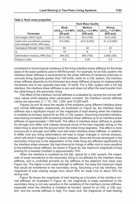
The range of tunnel size, ground cover, rock mass properties, relative lining stiff-ness, interface shear and normal stiffnesses, and mechanical properties assumed in the study are presented in Tables 1 and 2. Three rock mass strength values are used: 0.6, 2.4, and 4.5 MPa (90, 350, and 650 psi). The terms “weak,” “medium,” and “strong” correspond to these three rock mass types, respectively. These terms are defined to distinguish the rock mass types for discussion purposes. The quality of these rock mass types should not be equated to these terminologies as defined by ISRM (1981), where rock is classified in terms of intact rock strength.
Unless otherwise indicated, all analyses carried out in the sensitivity study are based on a horse-shoe shaped tunnel with a ground cover to tunnel width ratio equal to 3.
Effect of Interface StiffnessThe effect of the interface stiffness on the magnitude of loads transferred from the initial lining to the secondary lining is evaluated by analyzing cases with different shear stiffness (Ks) values while keeping other parameters unchanged. Six interface shear stiffness values are assumed: 0 (full slip), 1, 10, 100, 1,000, and 10,000 ksi/ft (see Table 1 for metric conversions for all ksi/ft to MPa/m). The range of these values is
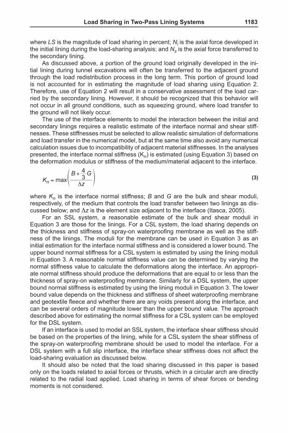
Table 1. Variables assumed in load sharing sensitivity studyParameter Value
Shear stiffness of interface (Ks), MPa/m (ksi/ft) 0, 22.6, 226, 2,260, 22,600, and 226,000 (0, 1, 10, 100, 1,000, and 10,000)
Normal stiffness of interface (Kn), MPa/m (ksi/ft) 0, 22.6, 226, 2,260, 22,600, and 226,000 (0, 1, 10, 100, 1,000, and 10,000)
Bonding condition Bonded and full slipRock mass strength (UCSrm), MPa (psi) 0.6, 2.4, 4.5 (90, 350, 650)Tunnel shape Circular and horse-shoe shapedTunnel diameter or width (D), m (ft) 3 and 15 (10 and 50)In situ horizontal-to-vertical stress ratio (Ko) 0.5, 1.0, and 2.0Secondary to initial lining stiffness ratio 2.0, 3.3, 4.0, and 6.7
Load Sharing in Two-Pass Lining Systems 1185
considered to bound typical variations of the lining interface shear stiffness for the three types of two-pass systems used in NATM tunnels. For example, for an SSL system, the interface shear stiffness is represented by the shear stiffness of hardened shotcrete or concrete lining (typically greater than 100 ksi/ft), while for a CSL system, the interface shear stiffness depends on the thickness and shear stiffness of spray-on waterproofing membrane and is low (typically less than 10 ksi/ft). For a DSL system with a full slip interface, the interface shear stiffness is zero and does not affect the load transfer from the initial lining to the secondary lining.
The effect of the interface normal stiffness is evaluated by varying the normal stiff-ness values while keeping other parameters constant. Six interface normal stiffness values are assumed: 0, 1, 10, 100, 1,000, and 10,000 ksi/ft.
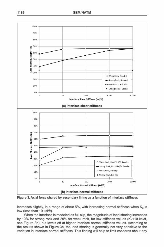
Figures 3a and 3b show the results of the analyses using different interface shear and normal stiffnesses, respectively. As illustrated on Figure 3a, the interface shear stiffness has a significant impact on the magnitude of load sharing when the interface is modeled as bonded, typical for an SSL or CSL system. Assuming a bonded interface, load sharing increases with increasing interface shear stiffness up to an interface shear stiffness of approximately 1,000 ksi/ft. The effect of interface shear stiffness is greater for stronger and stiffer rock masses because some of the load originally acting on the initial lining is shed into the ground when the initial lining degrades. This effect is more pronounced in stronger and stiffer rock with lower interface shear stiffness. In addition, in stiffer rock any lining deformations will lead to larger changes in normal stresses, which will result in larger changes in shear stresses. Since the thrusts developed in the secondary lining due to the degradation of the initial lining are affected significantly by the interface shear stresses, the load sharing for linings in stiffer rock is more sensitive to the interface shear stiffness. As shown in Figure 3a, the maximum magnitude of load sharing for a bonded condition is approximately 70%.
When the interface is modeled as full slip, typical for a DSL system, the magni-tude of loads transferred to the secondary lining is not affected by the interface shear stiffness, and is controlled primarily by the stiffness of the adjacent rock mass (see Figure 3a). The higher a rock mass strength or stiffness, the lower the maximum loads that would be transferred to the secondary lining. Assuming a full slip interface, the magnitude of load sharing ranges from about 50% for weak rock to about 35% for strong rock.
Figure 3b shows the magnitude of load sharing as a function of the interface nor-mal stiffness. As illustrated in Figure 3b, the magnitude of loads transferred to the secondary lining is not very sensitive to the variations of the interface normal stiffness, especially when the interface is modeled as bonded, typical for an SSL or CSL sys-tem, and the normal stiffness is high. For weak rock, the magnitude of load sharing
Table 2. Rock mass properties
Parameter
Rock Mass QualityWeak
(UCSrm = 0.6 MPa [90 psi])
Medium(UCSrm = 2.4 MPa
[350 psi])
Strong(UCSrm = 4.5 MPa
[650 psi])Unit weight, kN/m3 (pcf) 22.0 (140) 24.4 (155) 24.4 (155)Intact rock unconfined compres-sive strength (UCS), MPa (psi)
2.8 (400) 34.5 (5,000) 41.4 (6,000)
Geological Strength Index (GSI) 60 22 33mi 10 8 8Deformation modulus, MPa (ksi) 366 (53) 690 (100) 2,069 (300)Poisson’s ratio 0.2 0.25 0.3
1186 SEM/NATM
increases slightly, in a range of about 5%, with increasing normal stiffness when Kn is low (less than 10 ksi/ft).
When the interface is modeled as full slip, the magnitude of load sharing increases by 10% for strong rock and 20% for weak rock, for low stiffness values (Kn<10 ksi/ft, see Figure 3b), but levels off at higher interface normal stiffness values. According to the results shown in Figure 3b, the load sharing is generally not very sensitive to the variation in interface normal stiffness. This finding will help to limit concerns about any
(a) Interface shear stiffness
(b) Interface normal stiffnessFigure 3. Axial force shared by secondary lining as a function of interface stiffness
Load Sharing in Two-Pass Lining Systems 1187
potential uncertainties associated with estimation of an interface normal stiffness for use in analyses.
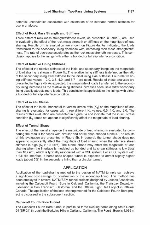
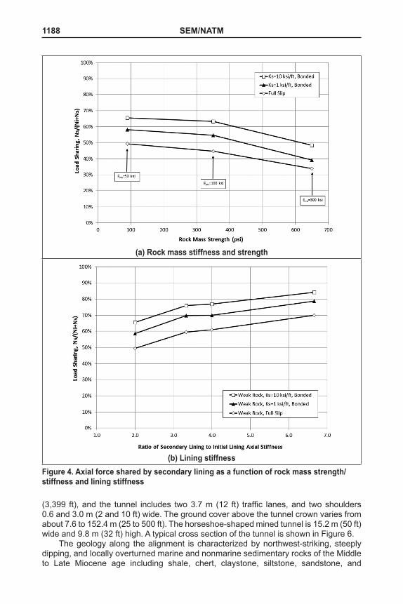
Effect of Rock Mass Strength and StiffnessThree different rock mass strength/stiffness levels, as presented in Table 2, are used in evaluating the effect of the rock mass strength or stiffness on the magnitude of load sharing. Results of this evaluation are shown on Figure 4a. As indicated, the loads transferred to the secondary lining decrease with increasing rock mass strength/stiff-ness. The rate of decrease accelerates as the rock mass strength increases. This con-clusion applies to the linings with either a bonded or full slip interface condition.
Effect of Relative Lining StiffnessThe effect of the relative stiffness of the initial and secondary linings on the magnitude of load sharing is shown in Figure 4b. The relative lining stiffness is defined as the ratio of the secondary lining axial stiffness to the initial lining axial stiffness. Four relative lin-ing stiffness values—2.0, 3.3, 4.0, and 6.7—are used. Results of these analyses are presented in Figure 4b. As expected, the magnitude of loads transferred to the second-ary lining increases as the relative lining stiffness increases because a stiffer secondary lining usually attracts more loads. This conclusion is applicable to the linings with either a bonded or full slip interface condition.
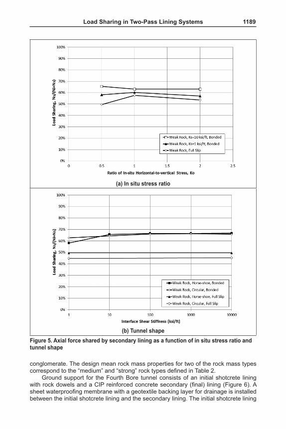
Effect of in situ StressThe effect of the in situ horizontal-to-vertical stress ratio (Ko) on the magnitude of load sharing is evaluated for cases with three different Ko values: 0.5, 1.0, and 2.0. The results of this evaluation are presented in Figure 5a and indicate that the in situ stress condition (Ko) does not appear to significantly affect the magnitude of load sharing.
Effect of Tunnel ShapeThe effect of the tunnel shape on the magnitude of load sharing is evaluated by com-paring the results for cases with circular and horse-shoe shaped tunnels. The results of this evaluation are presented in Figure 5b. In general, the tunnel shape does not appear to significantly affect the magnitude of load sharing when the interface shear stiffness is high (Ks > 10 ksi/ft). The tunnel shape may affect the magnitude of load sharing when the interface is modeled as bonded and its shear stiffness is low (less than 10 ksi/ft), which is typically associated with a CSL system. For a DSL system with a full slip interface, a horse-shoe-shaped tunnel is expected to attract slightly higher loads (about 5%) in the secondary lining than a circular tunnel.
APPLICATIONApplication of the load-sharing method to the design of NATM tunnels can achieve a significant cost savings for construction of the secondary lining. This method has been employed in several NATM/SEM tunnel projects designed by Jacobs Associates, including the Caldecott Fourth Bore in Oakland, California; the Transbay Downtown Extension in San Francisco, California; and the Ottawa Light Rail Project in Ottawa, Canada. The application of the load-sharing method for the Caldecott Fourth Bore proj-ect is discussed in the subsequent section.
Caldecott Fourth Bore TunnelThe Caldecott Fourth Bore tunnel is parallel to three existing bores along State Route 24 (SR 24) through the Berkeley Hills in Oakland, California. The Fourth Bore is 1,036 m
1188 SEM/NATM
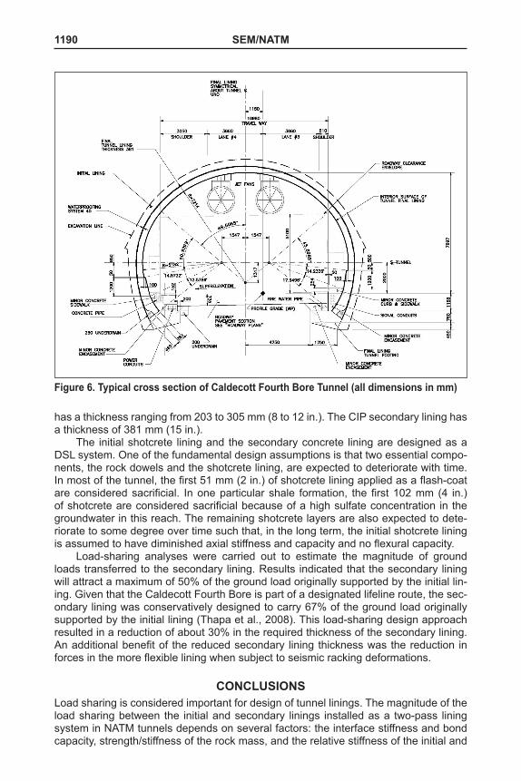
(3,399 ft), and the tunnel includes two 3.7 m (12 ft) traffic lanes, and two shoulders 0.6 and 3.0 m (2 and 10 ft) wide. The ground cover above the tunnel crown varies from about 7.6 to 152.4 m (25 to 500 ft). The horseshoe-shaped mined tunnel is 15.2 m (50 ft) wide and 9.8 m (32 ft) high. A typical cross section of the tunnel is shown in Figure 6.
The geology along the alignment is characterized by northwest-striking, steeply dipping, and locally overturned marine and nonmarine sedimentary rocks of the Middle to Late Miocene age including shale, chert, claystone, siltstone, sandstone, and
(a) Rock mass stiffness and strength
(b) Lining stiffnessFigure 4. Axial force shared by secondary lining as a function of rock mass strength/stiffness and lining stiffness
Load Sharing in Two-Pass Lining Systems 1189
conglomerate. The design mean rock mass properties for two of the rock mass types correspond to the “medium” and “strong” rock types defined in Table 2.
Ground support for the Fourth Bore tunnel consists of an initial shotcrete lining with rock dowels and a CIP reinforced concrete secondary (final) lining (Figure 6). A sheet waterproofing membrane with a geotextile backing layer for drainage is installed between the initial shotcrete lining and the secondary lining. The initial shotcrete lining
(a) In situ stress ratio
(b) Tunnel shapeFigure 5. Axial force shared by secondary lining as a function of in situ stress ratio and tunnel shape
1190 SEM/NATM
has a thickness ranging from 203 to 305 mm (8 to 12 in.). The CIP secondary lining has a thickness of 381 mm (15 in.).
The initial shotcrete lining and the secondary concrete lining are designed as a DSL system. One of the fundamental design assumptions is that two essential compo-nents, the rock dowels and the shotcrete lining, are expected to deteriorate with time. In most of the tunnel, the first 51 mm (2 in.) of shotcrete lining applied as a flash-coat are considered sacrificial. In one particular shale formation, the first 102 mm (4 in.) of shotcrete are considered sacrificial because of a high sulfate concentration in the groundwater in this reach. The remaining shotcrete layers are also expected to dete-riorate to some degree over time such that, in the long term, the initial shotcrete lining is assumed to have diminished axial stiffness and capacity and no flexural capacity.
Load-sharing analyses were carried out to estimate the magnitude of ground loads transferred to the secondary lining. Results indicated that the secondary lining will attract a maximum of 50% of the ground load originally supported by the initial lin-ing. Given that the Caldecott Fourth Bore is part of a designated lifeline route, the sec-ondary lining was conservatively designed to carry 67% of the ground load originally supported by the initial lining (Thapa et al., 2008). This load-sharing design approach resulted in a reduction of about 30% in the required thickness of the secondary lining. An additional benefit of the reduced secondary lining thickness was the reduction in forces in the more flexible lining when subject to seismic racking deformations.
CONCLUSIONSLoad sharing is considered important for design of tunnel linings. The magnitude of the load sharing between the initial and secondary linings installed as a two-pass lining system in NATM tunnels depends on several factors: the interface stiffness and bond capacity, strength/stiffness of the rock mass, and the relative stiffness of the initial and
Figure 6. Typical cross section of Caldecott Fourth Bore Tunnel (all dimensions in mm)
Load Sharing in Two-Pass Lining Systems 1191
secondary linings. Other factors, such as, tunnel shape and in situ stress condition, are not expected to significantly affect the magnitude of load sharing. The findings from the investigation presented in this paper can be summarized as follows:
■ For an SSL or CSL system, the interface shear stiffness has a significant effect on the magnitude of load sharing. This effect is more pronounced in stronger and stiffer rock. For a DSL system, the magnitude of loads trans-ferred to the secondary lining is not affected by the interface shear stiffness, and is controlled primarily by the stiffness of the rock mass.
■ Load sharing is generally not sensitive to the variation in interface normal stiffness, except for the DSL system assuming low interface normal stiffness.
■ The magnitude of loads transferred from the initial lining to the secondary lin-ing decreases with increasing rock mass strength/stiffness.
■ The magnitude of loads transferred to the secondary lining increases as the relative stiffness of the secondary lining increases.
■ The maximum ground load that the secondary lining is expected to support ranges from 50 to 70% of that originally carried by the initial lining. The use of load sharing in the design of a tunnel’s secondary or final lining can lead to an efficient design solution and, consequently, result in a savings in project costs.
The results and conclusions presented in this paper represent the findings based on the assumptions and limited range of parameters used. Further investigations that include a broader range of parameters related to the interface stiffness, tunnel shape, lining stiffness, ground and other loading conditions, etc. are warranted in order for one to have a comprehensive understanding of load sharing and its implications for the tun-nel secondary lining design.
ACKNOWLEDGMENTSThe authors would like to thank the California Department of Transportation (Caltrans) for its permission to publish this paper. The contents of this paper reflect the views of the authors, who are responsible for the facts and accuracy of the data presented herein, and do not necessarily reflect the official views or policies of the State of California. This paper does not constitute a standard, specification, or regulation.
REFERENCESHoek, E. 2002. Personal communication between L. Marcher and E. Hoek, quoted in
Load Sharing between Initial Support and Final Lining, ILF internal memo A139/AD-0001, Rev.0, May 2005.
International Society for Rock Mechanics (ISRM). 1981, Rock Characterization Testing & Monitoring, ISRM Suggested Methods. Edited by E.T. Brown. Oxford, England: Pergamon Press.
Itasca Consulting Group Inc. 2005. Fast Lagrangian Analysis of Continua (FLAC) Version 5.0, Minneapolis.
Nordstrom, E., 2005. Durability of Sprayed Concrete, Steel Fiber Corrosion in Cracks. Doctoral Thesis, Lulea University of Technology. Sweden.
Santhanam, M., Cohen, M.D., and Olek, J. 2002. Mechanism of sulfate attack: A fresh look; Part 1: Summary of experimental results, Cement and Concrete Research, 32, 915–921.
Thapa, B.B., Van Greunen, J., Sun, Y., McRae, M.T., and Law, H. 2008. Design analy-ses for a large-span tunnel in weak rock subject to strong seismic shaking. In Proc. of 2008 North American Tunneling Conference. San Francisco, CA, June 8–11, Society for Mining, Metallurgy, and Exploration, Inc. Littleton, CO: SME, 417–427.