LOAD PATH METHOD IN THE OPTIMUM DESIGN OF CABLE SUPPORTED ... path method in the... · LOAD PATH...
12
LOAD PATH METHOD IN THE OPTIMUM DESIGN OF CABLE SUPPORTED BRIDGES PALMISANO, Fabrizio VITONE, Amedeo Politecnico di Bari, Studio Vitone & Associati Politecnico di Bari, Studio Vitone & Associati Italy Italy VITONE, Claudia MININNI, Vito Antonio Politecnico di Bari Consultant Engineer Italy Italy Summary Born as a method to design Strut-and-Tie Models in reinforced concrete structures, the Load Path Method (LPM) shows its effectiveness in the easy perception of the physical behaviour of a structure, from its global behaviour to the most accurate details. In this paper, the use of LPM in the shape optimum design of cable supported bridges is presented and analytical relations, both in terms of strain energy and in terms of structural volumes are proposed. Keywords Bridge Design, Optimum Design, Strut-and-Tie Model, Load Path Method, Strain energy 1. Introduction Models have always been useful instruments to foresee the characteristics of a work. Only after Galilei this custom entered the heritage of Science and then models became also tools to simulate and to analyse structural behaviour; in the nineteenth century, Sir Benjamin Baker made a ‘human cantilever’ model of his Forth Railway Bridge with his Japanese assistant Mr. Wantanabe representing the live load in the middle (Fig. 1). Nowadays, a model has to show how shape, structure and environment become integrated in perfect harmony. A model should not be only a method to understand structural behaviour, but also a clear and effective instrument of investigation and judgement. Pablo Picasso used to say that the best bridge is the one which could be reduced to a thread, a line, without anything left over; which fulfilled strictly its function of uniting two separated distances. Bridges should be light, transparent. Their beauty, in general, should come from their economic structural shape: in geometrical contours of bridges, maybe more than in other architectural works, it is possible to recognise the expression, almost exclusive, of structural functionality. More than in other civil engineering works, load paths in bridges draw their profile. That is why, at present, the right model in bridge design is the one that opens new prospects in the search for a common language between engineers and architects to give voice, in harmony and in a single design, to formal, aesthetical, functional and structural aspects. 2. Load Path Method: basic principles Born as a method to design Strut-and-Tie Models [SCHLAICH et al., 1996] in reinforced concrete structures (Art. 5.6.4 EN 1992-1-1 [CEN, 2004]), the Load Path Method (whose basic principles are more widely illustrated in references [VITONE et al., 2001; PALMISANO, 2001; PALMISANO et al., 2002; PALMISANO et al., 2003; DE TOMMASI et al., 2003; BAGLIVI et al., 2003; PALMISANO,
Transcript of LOAD PATH METHOD IN THE OPTIMUM DESIGN OF CABLE SUPPORTED ... path method in the... · LOAD PATH...

LOAD PATH METHOD IN THE OPTIMUM DESIGN OF CABLE SUPPORTED BRIDGES
PALMISANO, Fabrizio VITONE, Amedeo
Politecnico di Bari, Studio Vitone & Associati Politecnico di Bari, Studio Vitone & Associati Italy Italy
VITONE, Claudia MININNI, Vito Antonio Politecnico di Bari Consultant Engineer
Italy Italy Summary Born as a method to design Strut-and-Tie Models in reinforced concrete structures, the Load Path Method (LPM) shows its effectiveness in the easy perception of the physical behaviour of a structure, from its global behaviour to the most accurate details. In this paper, the use of LPM in the shape optimum design of cable supported bridges is presented and analytical relations, both in terms of strain energy and in terms of structural volumes are proposed. Keywords Bridge Design, Optimum Design, Strut-and-Tie Model, Load Path Method, Strain energy 1. Introduction Models have always been useful instruments to foresee the characteristics of a work. Only after Galilei this custom entered the heritage of Science and then models became also tools to simulate and to analyse structural behaviour; in the nineteenth century, Sir Benjamin Baker made a ‘human cantilever’ model of his Forth Railway Bridge with his Japanese assistant Mr. Wantanabe representing the live load in the middle (Fig. 1). Nowadays, a model has to show how shape, structure and environment become integrated in perfect harmony. A model should not be only a method to understand structural behaviour, but also a clear and effective instrument of investigation and judgement. Pablo Picasso used to say that the best bridge is the one which could be reduced to a thread, a line, without anything left over; which fulfilled strictly its function of uniting two separated distances. Bridges should be light, transparent. Their beauty, in general, should come from their economic structural shape: in geometrical contours of bridges, maybe more than in other architectural works, it is possible to recognise the expression, almost exclusive, of structural functionality. More than in other civil engineering works, load paths in bridges draw their profile. That is why, at present, the right model in bridge design is the one that opens new prospects in the search for a common language between engineers and architects to give voice, in harmony and in a single design, to formal, aesthetical, functional and structural aspects. 2. Load Path Method: basic principles Born as a method to design Strut-and-Tie Models [SCHLAICH et al., 1996] in reinforced concrete structures (Art. 5.6.4 EN 1992-1-1 [CEN, 2004]), the Load Path Method (whose basic principles are more widely illustrated in references [VITONE et al., 2001; PALMISANO, 2001; PALMISANO et al., 2002; PALMISANO et al., 2003; DE TOMMASI et al., 2003; BAGLIVI et al., 2003; PALMISANO,
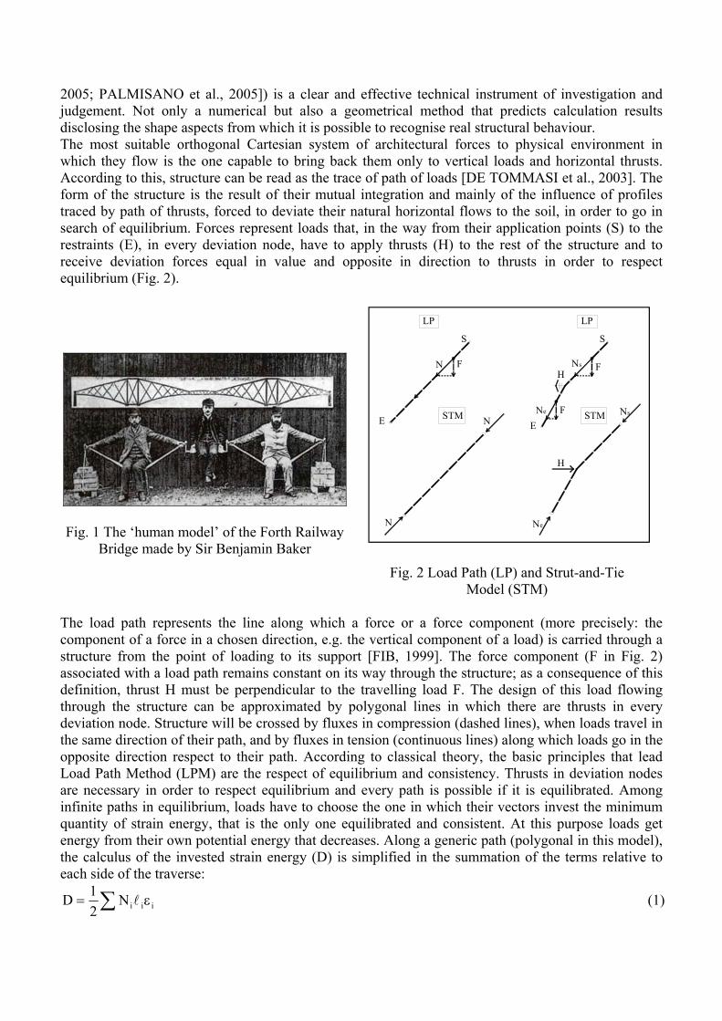
2005; PALMISANO et al., 2005]) is a clear and effective technical instrument of investigation and judgement. Not only a numerical but also a geometrical method that predicts calculation results disclosing the shape aspects from which it is possible to recognise real structural behaviour. The most suitable orthogonal Cartesian system of architectural forces to physical environment in which they flow is the one capable to bring back them only to vertical loads and horizontal thrusts. According to this, structure can be read as the trace of path of loads [DE TOMMASI et al., 2003]. The form of the structure is the result of their mutual integration and mainly of the influence of profiles traced by path of thrusts, forced to deviate their natural horizontal flows to the soil, in order to go in search of equilibrium. Forces represent loads that, in the way from their application points (S) to the restraints (E), in every deviation node, have to apply thrusts (H) to the rest of the structure and to receive deviation forces equal in value and opposite in direction to thrusts in order to respect equilibrium (Fig. 2).
Fig. 1 The ‘human model’ of the Forth Railway Bridge made by Sir Benjamin Baker
F
LP
N
N
N
LP
STM
Ns F
S
E
S
ENe F STM Ns
Ne
H
H
Fig. 2 Load Path (LP) and Strut-and-Tie Model (STM)
The load path represents the line along which a force or a force component (more precisely: the component of a force in a chosen direction, e.g. the vertical component of a load) is carried through a structure from the point of loading to its support [FIB, 1999]. The force component (F in Fig. 2) associated with a load path remains constant on its way through the structure; as a consequence of this definition, thrust H must be perpendicular to the travelling load F. The design of this load flowing through the structure can be approximated by polygonal lines in which there are thrusts in every deviation node. Structure will be crossed by fluxes in compression (dashed lines), when loads travel in the same direction of their path, and by fluxes in tension (continuous lines) along which loads go in the opposite direction respect to their path. According to classical theory, the basic principles that lead Load Path Method (LPM) are the respect of equilibrium and consistency. Thrusts in deviation nodes are necessary in order to respect equilibrium and every path is possible if it is equilibrated. Among infinite paths in equilibrium, loads have to choose the one in which their vectors invest the minimum quantity of strain energy, that is the only one equilibrated and consistent. At this purpose loads get energy from their own potential energy that decreases. Along a generic path (polygonal in this model), the calculus of the invested strain energy (D) is simplified in the summation of the terms relative to each side of the traverse:
iiiN21D ε= ∑ l (1)
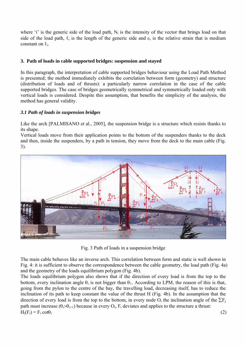
where ‘i’ is the generic side of the load path, Ni is the intensity of the vector that brings load on that side of the load path, ℓi is the length of the generic side and εi is the relative strain that is medium constant on ℓi. 3. Path of loads in cable supported bridges: suspension and stayed In this paragraph, the interpretation of cable supported bridges behaviour using the Load Path Method is presented; the method immediately exhibits the correlation between form (geometry) and structure (distribution of loads and of thrusts): a particularly narrow correlation in the case of the cable supported bridges. The case of bridges geometrically symmetrical and symmetrically loaded only with vertical loads is considered. Despite this assumption, that benefits the simplicity of the analysis, the method has general validity. 3.1 Path of loads in suspension bridges Like the arch [PALMISANO et al., 2005], the suspension bridge is a structure which resists thanks to its shape. Vertical loads move from their application points to the bottom of the suspenders thanks to the deck and then, inside the suspenders, by a path in tension, they move from the deck to the main cable (Fig. 3).
Fig. 3 Path of loads in a suspension bridge The main cable behaves like an inverse arch. This correlation between form and static is well shown in Fig. 4: it is sufficient to observe the correspondence between the cable geometry, the load path (Fig. 4a) and the geometry of the loads equilibrium polygon (Fig. 4b). The loads equilibrium polygon also shows that if the direction of every load is from the top to the bottom, every inclination angle θi is not bigger than θ1. According to LPM, the reason of this is that, going from the pylon to the centre of the bay, the travelling load, decreasing itself, has to reduce the inclination of its path to keep constant the value of the thrust H (Fig. 4b). In the assumption that the direction of every load is from the top to the bottom, in every node Oi the inclination angle of the ∑Fj path must increase (θi>θi+1) because in every Oi, Fi deviates and applies to the structure a thrust: Hi(Fi) = Fi cotθi (2)

For equilibrium reasons (≡ to make possible the Fi deviation) ∑Fj, coming from the top, must deviate in Oi of δi, increasing the inclination angle from θi+1 to θi, and must apply a thrust equal in value (but opposite in direction) to the Fi one (Fig. 4c): Hi(∑Fj) = ∑Fj (cotθi+1 - cotθi) (3) Because of the equilibrium of these two thrusts it is possible that loads go from their application points to the pylons only by a path in tension. Equation (3) analytically shows what Fig. 4 exhibits graphically: the line of the “possible” (≡ in equilibrium) LP is strictly related to the intensity and distribution of loads Fi.
Fig. 4 The main cable as path of vertical loads
Fig. 5 The main cable as path of the thrust
It is also possible to interpret the loads ∑Fj path as the one of the thrust H (Fig. 5). In this case, the travelling load does not change (if every Fi is vertical). In every node the thrust path (from the pylon to the centre) deviates of δi, changing its inclination from θi to θi+1. This is possible (≡ in equilibrium) because in every node Oi, the vertical thrust Vi (directed from the bottom to the top) of H is equilibrated by the load Fi which is equal in value but opposite in direction. Even if, as above mentioned, there is a strict similarity between the main cable and a arch, there is also a basic difference. In fact, the suspension bridge main cable because of its lack of bending stiffness, must always coincide with the load system antifunicular polygon; this is why, when the system changes, the cable must change shape to fit the funicular again.
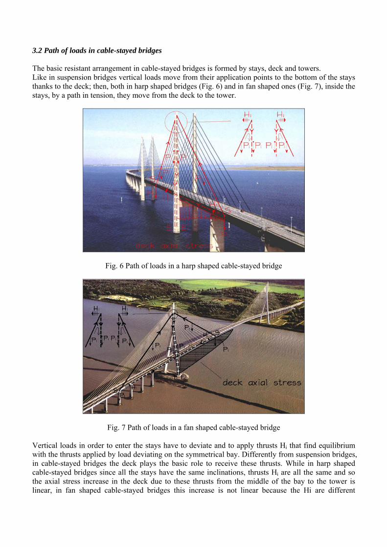
3.2 Path of loads in cable-stayed bridges The basic resistant arrangement in cable-stayed bridges is formed by stays, deck and towers. Like in suspension bridges vertical loads move from their application points to the bottom of the stays thanks to the deck; then, both in harp shaped bridges (Fig. 6) and in fan shaped ones (Fig. 7), inside the stays, by a path in tension, they move from the deck to the tower.
Fig. 6 Path of loads in a harp shaped cable-stayed bridge
Fig. 7 Path of loads in a fan shaped cable-stayed bridge Vertical loads in order to enter the stays have to deviate and to apply thrusts Hi that find equilibrium with the thrusts applied by load deviating on the symmetrical bay. Differently from suspension bridges, in cable-stayed bridges the deck plays the basic role to receive these thrusts. While in harp shaped cable-stayed bridges since all the stays have the same inclinations, thrusts Hi are all the same and so the axial stress increase in the deck due to these thrusts from the middle of the bay to the tower is linear, in fan shaped cable-stayed bridges this increase is not linear because the Hi are different
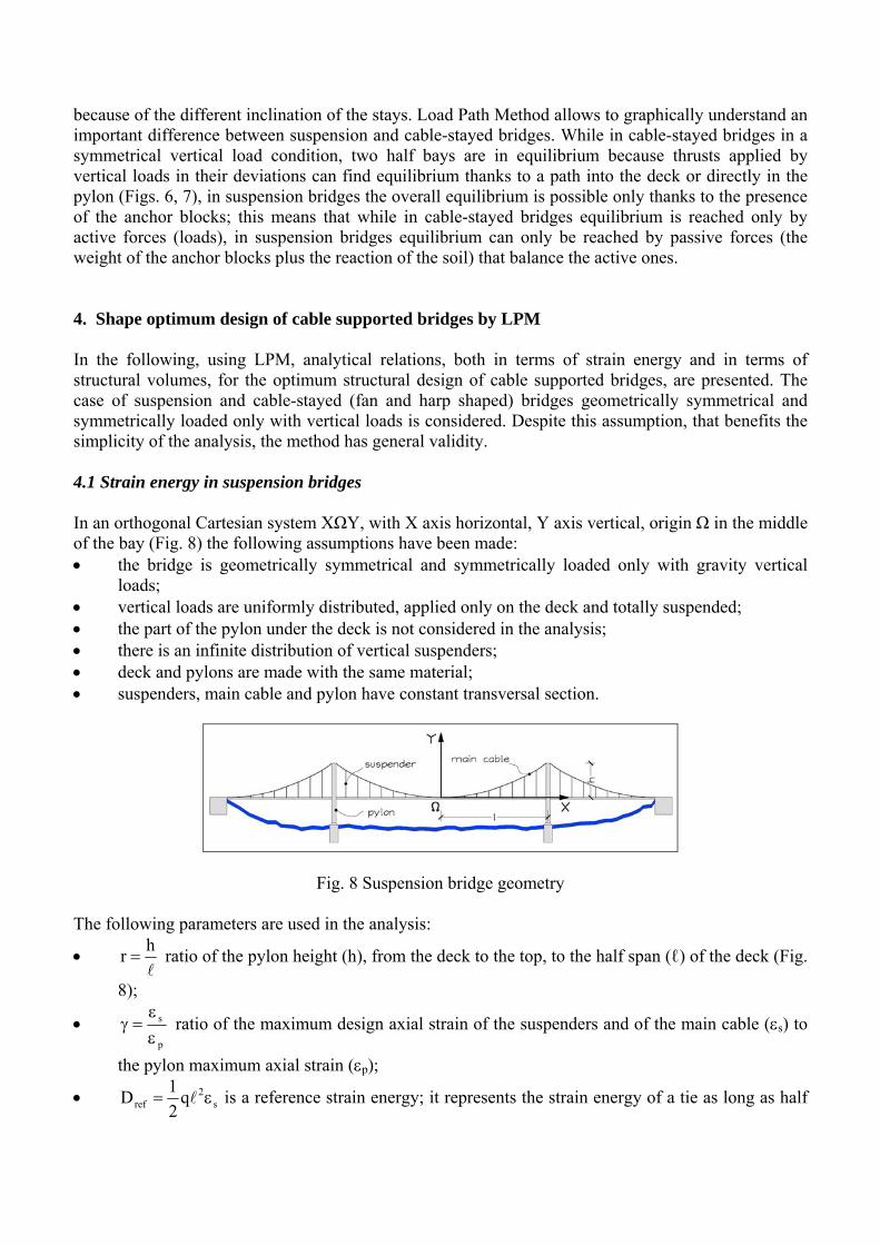
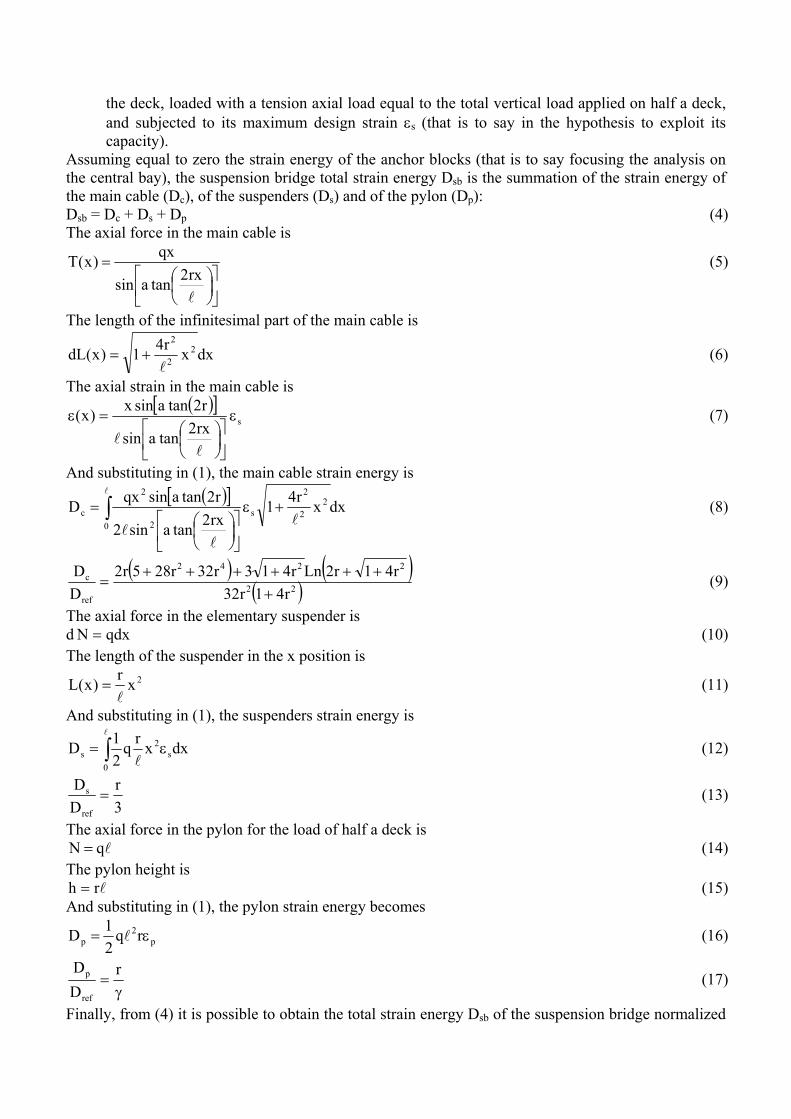
because of the different inclination of the stays. Load Path Method allows to graphically understand an important difference between suspension and cable-stayed bridges. While in cable-stayed bridges in a symmetrical vertical load condition, two half bays are in equilibrium because thrusts applied by vertical loads in their deviations can find equilibrium thanks to a path into the deck or directly in the pylon (Figs. 6, 7), in suspension bridges the overall equilibrium is possible only thanks to the presence of the anchor blocks; this means that while in cable-stayed bridges equilibrium is reached only by active forces (loads), in suspension bridges equilibrium can only be reached by passive forces (the weight of the anchor blocks plus the reaction of the soil) that balance the active ones. 4. Shape optimum design of cable supported bridges by LPM In the following, using LPM, analytical relations, both in terms of strain energy and in terms of structural volumes, for the optimum structural design of cable supported bridges, are presented. The case of suspension and cable-stayed (fan and harp shaped) bridges geometrically symmetrical and symmetrically loaded only with vertical loads is considered. Despite this assumption, that benefits the simplicity of the analysis, the method has general validity. 4.1 Strain energy in suspension bridges In an orthogonal Cartesian system XΩY, with X axis horizontal, Y axis vertical, origin Ω in the middle of the bay (Fig. 8) the following assumptions have been made: • the bridge is geometrically symmetrical and symmetrically loaded only with gravity vertical
loads; • vertical loads are uniformly distributed, applied only on the deck and totally suspended; • the part of the pylon under the deck is not considered in the analysis; • there is an infinite distribution of vertical suspenders; • deck and pylons are made with the same material; • suspenders, main cable and pylon have constant transversal section.
Fig. 8 Suspension bridge geometry The following parameters are used in the analysis:
• l
hr = ratio of the pylon height (h), from the deck to the top, to the half span (ℓ) of the deck (Fig.
8);
• p
s
εε
=γ ratio of the maximum design axial strain of the suspenders and of the main cable (εs) to
the pylon maximum axial strain (εp);
• s2
ref q21D ε= l is a reference strain energy; it represents the strain energy of a tie as long as half
the deck, loaded with a tension axial load equal to the total vertical load applied on half a deck, and subjected to its maximum design strain εs (that is to say in the hypothesis to exploit its capacity).
Assuming equal to zero the strain energy of the anchor blocks (that is to say focusing the analysis on the central bay), the suspension bridge total strain energy Dsb is the summation of the strain energy of the main cable (Dc), of the suspenders (Ds) and of the pylon (Dp): Dsb = Dc + Ds + Dp (4) The axial force in the main cable is
⎥⎦
⎤⎢⎣
⎡⎟⎠⎞
⎜⎝⎛
=
l
rx2tanasin
qx)x(T (5)
The length of the infinitesimal part of the main cable is
dxxr41)x(dL 22
2
l+= (6)
The axial strain in the main cable is ( )[ ]
srx2tanasin
r2tanasinx)x( ε
⎥⎦
⎤⎢⎣
⎡⎟⎠⎞
⎜⎝⎛
=ε
ll
(7)
And substituting in (1), the main cable strain energy is ( )[ ]
∫ +ε
⎥⎦
⎤⎢⎣
⎡⎟⎠⎞
⎜⎝⎛
=l
l
ll0
22
2
s2
2
c dxxr41rx2tanasin2
r2tanasinqxD (8)
( ) ( )( )22
2242
ref
c
r41r32r41r2Lnr413r32r285r2
DD
+++++++
= (9)
The axial force in the elementary suspender is d qdxN = (10) The length of the suspender in the x position is
2xr)x(Ll
= (11)
And substituting in (1), the suspenders strain energy is
∫ ε=l
l0s
2s dxxrq
21D (12)
3r
DD
ref
s = (13)
The axial force in the pylon for the load of half a deck is lqN = (14)
The pylon height is lrh = (15)
And substituting in (1), the pylon strain energy becomes
p2
p rq21D ε= l (16)
γ=
rDD
ref
p (17)
Finally, from (4) it is possible to obtain the total strain energy Dsb of the suspension bridge normalized

by Dref: ( ) ( )
( ) γ++
+++++++
=r
3r
r41r32r41r2Lnr413r32r285r2
DD
22
2242
ref
sb (18)
4.2 Strain energy in cable-stayed bridges In an orthogonal Cartesian system XΩY, with X axis horizontal, Y axis vertical, origin Ω at the intersection between the deck and the tower (Figs. 9, 10), the following assumptions have been made: • the bridge is geometrically symmetrical and symmetrically loaded only with gravity vertical
loads; • vertical loads are uniformly distributed, applied only on the deck and totally suspended; • the part of the pylon under the deck is not considered in the analysis; • there is an infinite distribution of stays; • deck and pylons are made with the same material; • stays have constant transversal section; • pylons have constant transversal section in the fan shaped bridge; • pylons have not constant section in the harp shaped bridge in order to have in every section the
same axial strain; • only with reference to the actions generated by the analysed model, deck has in every section the
same axial strain.
Fig. 9 Fan shaped cable-stayed bridge geometry
Fig. 10 Harp shaped cable-stayed bridge geometry In the analysis, the following parameters are used:
• l
hr = ratio of the pylon height (h), from the deck to the top, to the half span (ℓ) of the deck
(Figs. 9, 10);
• d
s
p
s
εε
=εε
=γ ratio of the stays maximum design axial strain (εs) to the maximum design axial
strain of the pylon (εp) and of the deck (εd);
• s2
ref q21D ε= l is a reference strain energy; it represents the strain energy of a tie as long as half
the deck, loaded with a tension axial load equal to the total vertical load applied on half a deck, and subjected to its maximum design strain εs (that is to say in the hypothesis to exploit its capacity).
The total strain energy Dfcb of the fan shaped cable-stayed bridge is the summation of the strain energy of the stays (Ds), of the deck (Dd) and of the pylon (Dp): Dfcb = Ds + Dd +Dp (19) With the same procedure used for the suspension bridge it is possible to obtain
γ+
γ++=
rr31r
r31
DD
ref
fcb (20)
The total strain energy Dhcb of the harp shaped cable-stayed bridge is the summation of the strain energy of the stays (Ds), of the deck (Dd) and of the pylon (Dp): Dhcb = Ds + Dd +Dp (21) Using the same procedure of the suspension bridge it is possible to obtain
γ+
γ++=
2r
r21
2r
r21
DD
ref
hcb (22)
4.3 Structural volumes in suspension bridges In the analysis the same assumptions made in par. 4.1 and the following parameters are used:
• l
hr = ratio of the pylon height (h), from the deck to the top, to the half span (ℓ) of the deck (Fig.
8);
• p,d
yd
ff
k = ratio of the design yield strength of the suspenders and of the main cable (fyd) to the
pylon design strength (fd,p);
• yd
2
ref fqV l
= is a reference volume; it represents the structural volume of a tie as long as half the
deck, loaded with a tension axial load equal to the total vertical load applied on half a deck, and subjected to its design yield strength fyd.
Not considering the part of the total structural volume of the anchor blocks (that is to say focusing the analysis on the central bay), the suspension bridge total structural volume Vsb is the summation of the structural volume of the main cable (Vc), of the suspenders (Vs) and of the pylon (Vp): Vsb = Vc + Vs + Vp (23) The maximum axial force in the main cable is
( )[ ]r2tanasinqTmaxl
= (24)
The length of the main cable is
( )22
r41r2Lnr42
r41L ++++
=ll (25)
Thus the main cable structural volume is
( )[ ]( )
⎥⎥⎦
⎤
⎢⎢⎣
⎡
⎟⎟⎠
⎞⎜⎜⎝
⎛ +++
+==
r4r41r2Ln
2r41
r2tanasin1
fqL
fTV
22
yd
2
yd
maxc
l (26)
The axial force in the elementary suspender is d qdxN = (10) The length of the suspender in the x position is
2xr)x(Ll
= (11)
Then the suspender structural volume is
∫ ==l
l
l0 yd
22
yds 3
rfqdxxr
fqV (27)
The axial force in the pylon for the load of half a deck is
lqN = (14) The pylon height is
lrh = (15) Thus the pylon structural volume is
krfqr
fqV
yd
2
p,dp
ll
l== (28)
Finally, from (23) it is possible to obtain the total structural Vsb of the suspension bridge normalized by Vref:
( )[ ]( ) kr
3r
r4r41r2Ln
2r41
r2tanasin1
VV 22
ref
sb ++⎟⎟⎠
⎞⎜⎜⎝
⎛ +++
+= (29)
4.4 Structural volumes in cable-stayed bridges In the analysis the same assumptions made in par. 4.2 and the following parameters are used:
• l
hr = ratio of the pylon height (h), from the deck to the top, to the half span (ℓ) of the deck
(Figs. 9, 10);
• d,d
yd
p,d
yd
ff
ff
k == ratio of the stays design yield strength (fyd) to the design strength of the pylon
(fd,p) and of the deck (fd,d);
• yd
2
ref fqV l
= is a reference volume; it represents the structural volume of a tie as long as half the
deck, loaded with a tension axial load equal to the total vertical load applied on half a deck, and subjected to its design yield strength fyd.
The total structural volume Vfcb of the fan shaped cable-stayed bridge is the summation of the structural volumes of the stays (Vs), of the deck (Vd) and of the pylon (Vp): Vfcb = Vs + Vd + Vp (30) With the same procedure used for the suspension bridge it is possible to obtain
krr3
krr3
1VV
ref
fcb +++= (31)
The total structural volume Vhcb of the harp shaped cable-stayed bridge is the summation of the structural volumes of the stays (Vs), of the deck (Vd) and of the pylon (Vp): Vhcb = Vs + Vd +Vp (32) Using the same procedure of the suspension bridge it is possible to obtain
2kr
r2k
2r
r21
VV
ref
hcb +++= (33)
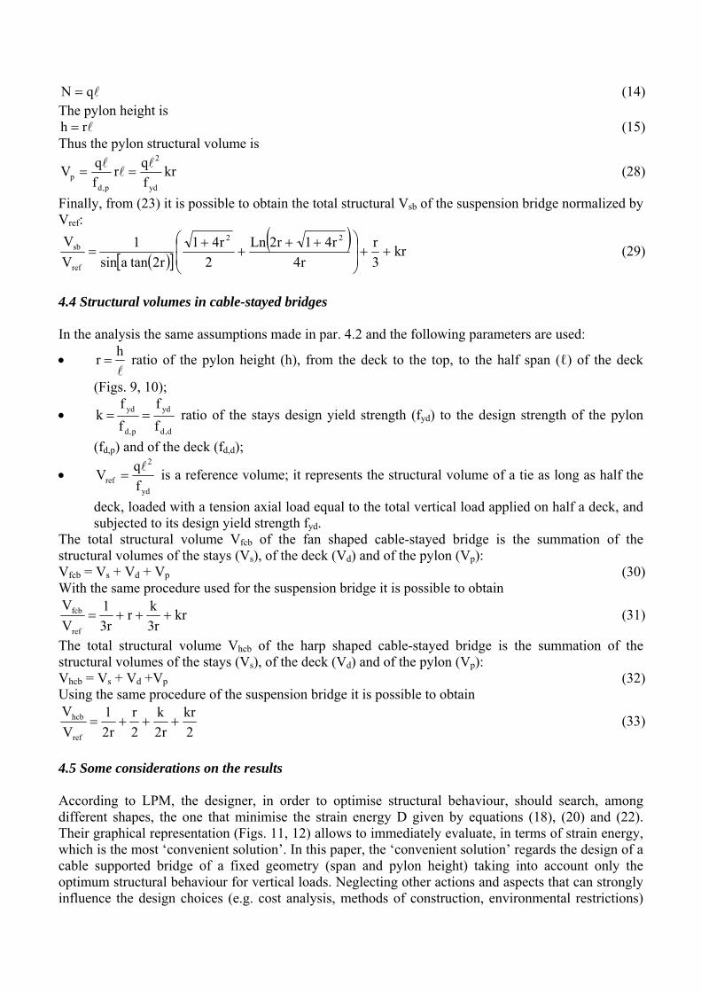
4.5 Some considerations on the results According to LPM, the designer, in order to optimise structural behaviour, should search, among different shapes, the one that minimise the strain energy D given by equations (18), (20) and (22). Their graphical representation (Figs. 11, 12) allows to immediately evaluate, in terms of strain energy, which is the most ‘convenient solution’. In this paper, the ‘convenient solution’ regards the design of a cable supported bridge of a fixed geometry (span and pylon height) taking into account only the optimum structural behaviour for vertical loads. Neglecting other actions and aspects that can strongly influence the design choices (e.g. cost analysis, methods of construction, environmental restrictions)
leads to assume that the satisfaction of the minimum value of strain energy coincides with the most ‘convenient solution’.
0.0
0.5
1.0
1.5
2.0
2.5
3.0
3.5
4.0
4.5
5.0
0.05
0.10
0.15
0.20
0.25
0.30
0.35
0.40
0.45
0.50
0.55
0.60
0.65
0.70
0.75
0.80
0.85
0.90
0.95
1.00
r
D/Dref
SUSPENDED FAN HARP
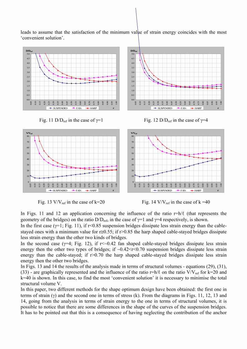
Fig. 11 D/Dref in the case of γ=1
0.0
0.5
1.0
1.5
2.0
2.5
3.0
3.5
4.0
4.5
5.0
0.05
0.10
0.15
0.20
0.25
0.30
0.35
0.40
0.45
0.50
0.55
0.60
0.65
0.70
0.75
0.80
0.85
0.90
0.95
1.00
r
D/Dref
SUSPENDED FAN HARP
Fig. 12 D/Dref in the case of γ=4
0
10
20
30
40
50
60
70
80
0.05
0.10
0.15
0.20
0.25
0.30
0.35
0.40
0.45
0.50
0.55
0.60
0.65
0.70
0.75
0.80
0.85
0.90
0.95
1.00
r
V/Vref
SUSPENDED FAN HARP
Fig. 13 V/Vref in the case of k=20
0
10
20
30
40
50
60
70
800.
05
0.10
0.15
0.20
0.25
0.30
0.35
0.40
0.45
0.50
0.55
0.60
0.65
0.70
0.75
0.80
0.85
0.90
0.95
1.00
r
V/Vref
SUSPENDED FAN HARP
Fig. 14 V/Vref in the case of k =40 In Figs. 11 and 12 an application concerning the influence of the ratio r=h/ℓ (that represents the geometry of the bridges) on the ratio D/Dref, in the case of γ=1 and γ=4 respectively, is shown. In the first case (γ=1; Fig. 11), if r<0.85 suspension bridges dissipate less strain energy than the cable-stayed ones with a minimum value for r≅0.55; if r>0.85 the harp shaped cable-stayed bridges dissipate less strain energy than the other two kinds of bridges. In the second case (γ=4; Fig. 12), if r<~0.42 fan shaped cable-stayed bridges dissipate less strain energy then the other two types of bridges; if ~0.42<r<0.70 suspension bridges dissipate less strain energy than the cable-stayed; if r>0.70 the harp shaped cable-stayed bridges dissipate less strain energy then the other two bridges. In Figs. 13 and 14 the results of the analysis made in terms of structural volumes - equations (29), (31), (33) - are graphically represented and the influence of the ratio r=h/ℓ on the ratio V/Vref for k=20 and k=40 is shown. In this case, to find the most ‘convenient solution’ it is necessary to minimise the total structural volume V. In this paper, two different methods for the shape optimum design have been obtained: the first one in terms of strain (γ) and the second one in terms of stress (k). From the diagrams in Figs. 11, 12, 13 and 14, going from the analysis in terms of strain energy to the one in terms of structural volumes, it is possible to notice that there are some differences in the shape of the curves of the suspension bridges. It has to be pointed out that this is a consequence of having neglecting the contribution of the anchor

blocks which is different in the two formulations. Further theoretical work is needed to take into account in the analysis also this effect. 5. Conclusions The load path method is an instrument to analyse structural continuum, as it seems to have the peculiar capacity to easily catch the physical behaviour of a structure, from its global behaviour to the most accurate details. In this study, the LPM basic principles have been applied to the shape optimum design of cable supported bridges in order to show LPM versatility and effectiveness. Besides, analytical relations, both in terms of strain energy and in terms of structural volumes, have been presented with the purpose of showing that LPM seems also to successfully conciliate the necessity to get a numerical solution and to never loose touch with the perception of the synthesis of physical structural behaviour. References BAGLIVI, N.L., PALMISANO, F., VITONE, A., VITONE, C., 2003, Load path method in the conceptual design of r.c. structures, Proc. of the 2nd Specialty Conference on the Conceptual Approach to Structural Design, 01-02 July 2003, Milano. CEN (EUROPEAN COMMITTEE FOR STANDARDIZATION), 2004, EN 1992-1-1:2004 Eurocode 2. Design of concrete structures. General rules and rules for buildings. DE TOMMASI, G., MONACO, P., VITONE, C., 2003, A first approach to load path method on the masonry structures behaviour, Structural Studies, Repairs and Maintenance of Heritage Architecture VIII, ed. C. A. Brebbia, WITpress, Southampton, United Kingdom, 2003: p287-296. FIB, 1999, Structural Concrete Textbook on Behaviour, Design and Performance. Volume 3, Bulletin 3. Sprint-Druck, Stuttgart, 1999. PALMISANO, F., 2001, L’organismo portante in c.a. ed i particolari esecutivi di un edificio residenziale, Costruire con il cemento armato, ed. M. Mezzina, Utet, Torino, 2001: p507-531. PALMISANO, F., 2005, Form and structure in the harmonious complexity of the building process: from conceptual design to detailing in some reinforced concrete works, Structural Concrete, Thomas Telford, London, 2005;6(3): p122-130. PALMISANO, F., VITONE, A., VITONE, C., 2002, Form & Structure. The Rome Auditorium: load path method (LPM), D’Architettura, Federico Motta Editore, Milano, 2002;18: p168-173. PALMISANO, F., VITONE, A., VITONE, C., 2003, From load path method to classical models of structural analysis, System-based Vision for Strategic and Creative Design (Proc. of the ISEC-02 - International Structural Engineering and Construction Conference, Rome, 23-26 September 2003), ed. F. Bontempi, A.A. Balkema Publishers, the Netherlands, 2003;1: p589-596. PALMISANO, F., VITONE, A., VITONE, C., 2005, Load path method in the interpretation of the masonry vaults behaviour, Structural Studies, Repairs and Maintenance of Heritage Architecture IX, ed. C.A. Brebbia & A. Torpiano, WITpress, Southampton, United Kingdom, 2005: p155-167. SCHLAICH, J., SCHAFER, K., 1996, Designing and detailing using Strut-and-tie Models, Proc. of the Workshop Strut-and-Tie Models for the Design of Structural Concrete, ed. K. Shafer, 1996, National Cheng Kung University, Tainan. VITONE, A., VITONE, V., 2001, Il cantiere: progettare e costruire. Lo stadio San Nicola di Bari, Costruire con il cemento armato, ed. M. Mezzina, Utet, Torino, 2001: p427-503.