LOAD MOMENT INDICATOR DS350 RCL...
27
SERVICE MANUAL P/N 031-300-190-038 REV. D 12/05/2005 www.patamerica.com LOAD MOMENT INDICATOR DS350 RCL Link-Belt Construction Equipment HIRSCHMANN LATTICE BOOM CRANES
Transcript of LOAD MOMENT INDICATOR DS350 RCL...
DS 350 TROUBLESHOOTING HANDBOOK 031-300-190-038 REVISION D 12/05/05
SERVICE MANUAL P/N 031-300-190-038 REV. D 12/05/2005
www.patamerica.com
LOAD MOMENT INDICATOR
DS350 RCL Link-Belt Construction Equipment
HIRSCHMANN
LATTICE BOOM CRANES

DS 350 TROUBLESHOOTING HANDBOOK
DS 350 TROUBLESHOOTING HANDBOOK 031-300-190-038 REVISION D 12/05/05
NOTICE
The information in this document is subject to change without notice.
Hirschmann makes no warranty of any kind with regard
to this material, including, but not limited to the implied warranties of merchantability
and fitness for a particular purpose.
Hirschmann shall not be liable for errors contained herein or for incidental or consequential damages in connection with the furnishing, performance
or use of this manual.
This document contains proprietary information which is protected by copyright. All rights are reserved. No part of this document may be photocopied, reproduced, or translated to
another language without prior consent of Hirschmann.
DS 350 TROUBLESHOOTING HANDBOOK
DS 350 TROUBLESHOOTING HANDBOOK 031-300-190-038 REVISION D 12/05/05
TABLE OF CONTENTS
NOTICE
GENERAL INFORMATION...................................................................................1
WARNINGS ..........................................................................................................1
1.0 ERROR CODE CHART ..................................................................................2
2.0 SYSTEM COMPONENT LAYOUT..................................................................6
3.0 ANGLE SENSOR ADJUSTMENT...................................................................7 3.1 ANGLE CIRCUIT (WG203) ......................................................................8 3.2 ANGLE CIRCUIT (WG206) ......................................................................9
4.0 LINERIDER SETTINGS AND ADJUSTMENTS ............................................10 4.0 General Information................................................................................10 4.1 Linerider Zero Point Adjustment .............................................................11 4.2 Linerider Output Adjustment...................................................................12 4.3 Linerider Circuits ....................................................................................13 4.4 Linerider Cannon Connection .................................................................14 5.0 DIGITAL INPUTS..........................................................................................15
6.0 ANTI-TWO BLOCK.......................................................................................16
7.0 BOOM BASE CABLE REEL DIAGRAM........................................................16
8.0 MAIN BOOM / JIB JUNCTION BOX DIAGRAMS .........................................17
9.0 LUFFING JIB JUNCTION BOX DIAGRAMS.................................................18
10.0 SYSTEM ( 12 VOLT ) WIRING DIAGRAM .................................................19 10.1 Vertical Console Diagram.....................................................................20
11.0 SYSTEM ( 24 VOLT ) DIAGRAM................................................................21 11.1 Horizontal Console Diagram ................................................................22
12.0 TERMINAL BOARD DESIGNATIONS ........................................................23 13.0 MAIN BOARD MEASURING POINTS ........................................................24
DS 350 TROUBLESHOOTING HANDBOOK
DS 350 TROUBLESHOOTING HANDBOOK 031-300-190-038 REVISION D 12/05/05
1
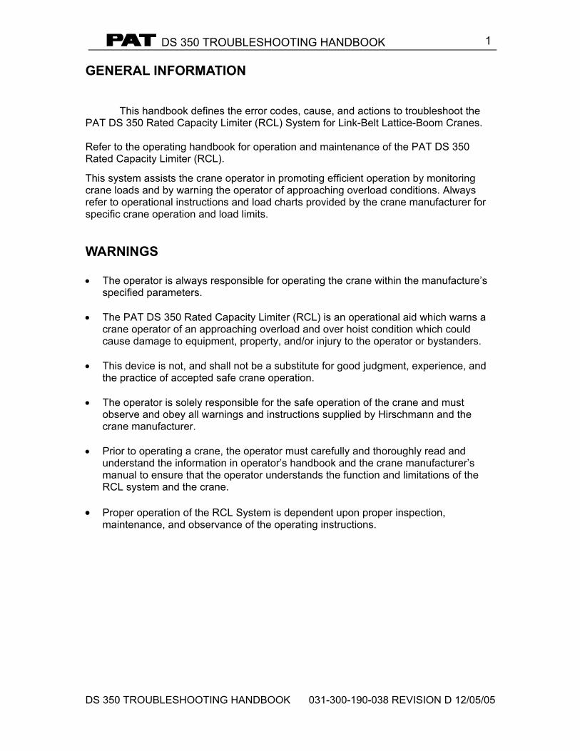
GENERAL INFORMATION This handbook defines the error codes, cause, and actions to troubleshoot the PAT DS 350 Rated Capacity Limiter (RCL) System for Link-Belt Lattice-Boom Cranes. Refer to the operating handbook for operation and maintenance of the PAT DS 350 Rated Capacity Limiter (RCL).
This system assists the crane operator in promoting efficient operation by monitoring crane loads and by warning the operator of approaching overload conditions. Always refer to operational instructions and load charts provided by the crane manufacturer for specific crane operation and load limits.
WARNINGS • The operator is always responsible for operating the crane within the manufacture’s
specified parameters. • The PAT DS 350 Rated Capacity Limiter (RCL) is an operational aid which warns a
crane operator of an approaching overload and over hoist condition which could cause damage to equipment, property, and/or injury to the operator or bystanders.
• This device is not, and shall not be a substitute for good judgment, experience, and
the practice of accepted safe crane operation. • The operator is solely responsible for the safe operation of the crane and must
observe and obey all warnings and instructions supplied by Hirschmann and the crane manufacturer.
• Prior to operating a crane, the operator must carefully and thoroughly read and
understand the information in operator’s handbook and the crane manufacturer’s manual to ensure that the operator understands the function and limitations of the RCL system and the crane.
• Proper operation of the RCL System is dependent upon proper inspection,
maintenance, and observance of the operating instructions.
DS 350 TROUBLESHOOTING HANDBOOK
DS 350 TROUBLESHOOTING HANDBOOK 031-300-190-038 REVISION D 12/05/05
2
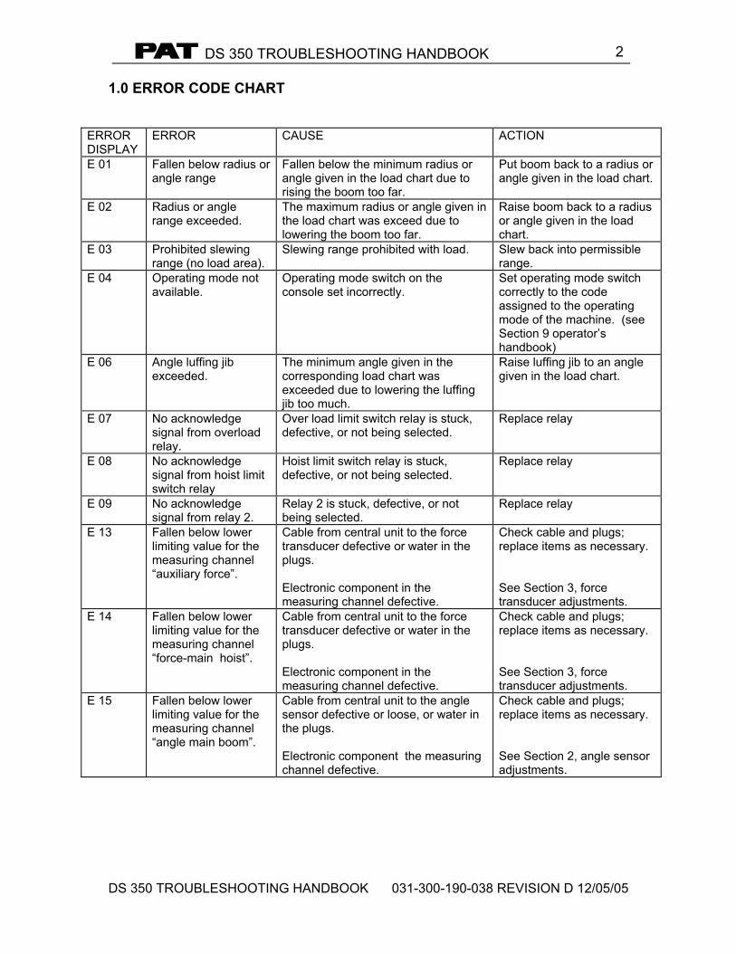
1.0 ERROR CODE CHART
ERROR DISPLAY
ERROR CAUSE ACTION
E 01 Fallen below radius or angle range
Fallen below the minimum radius or angle given in the load chart due to rising the boom too far.
Put boom back to a radius or angle given in the load chart.
E 02 Radius or angle range exceeded.
The maximum radius or angle given in the load chart was exceed due to lowering the boom too far.
Raise boom back to a radius or angle given in the load chart.
E 03 Prohibited slewing range (no load area).
Slewing range prohibited with load. Slew back into permissible range.
E 04 Operating mode not available.
Operating mode switch on the console set incorrectly.
Set operating mode switch correctly to the code assigned to the operating mode of the machine. (see Section 9 operator’s handbook)
E 06 Angle luffing jib exceeded.
The minimum angle given in the corresponding load chart was exceeded due to lowering the luffing jib too much.
Raise luffing jib to an angle given in the load chart.
E 07 No acknowledge signal from overload relay.
Over load limit switch relay is stuck, defective, or not being selected.
Replace relay
E 08 No acknowledge signal from hoist limit switch relay
Hoist limit switch relay is stuck, defective, or not being selected.
Replace relay
E 09 No acknowledge signal from relay 2.
Relay 2 is stuck, defective, or not being selected.
Replace relay
E 13 Fallen below lower limiting value for the measuring channel “auxiliary force”.
Cable from central unit to the force transducer defective or water in the plugs. Electronic component in the measuring channel defective.
Check cable and plugs; replace items as necessary. See Section 3, force transducer adjustments.
E 14 Fallen below lower limiting value for the measuring channel “force-main hoist”.
Cable from central unit to the force transducer defective or water in the plugs. Electronic component in the measuring channel defective.
Check cable and plugs; replace items as necessary. See Section 3, force transducer adjustments.
E 15 Fallen below lower limiting value for the measuring channel “angle main boom”.
Cable from central unit to the angle sensor defective or loose, or water in the plugs. Electronic component the measuring channel defective.
Check cable and plugs; replace items as necessary. See Section 2, angle sensor adjustments.
DS 350 TROUBLESHOOTING HANDBOOK
DS 350 TROUBLESHOOTING HANDBOOK 031-300-190-038 REVISION D 12/05/05
3
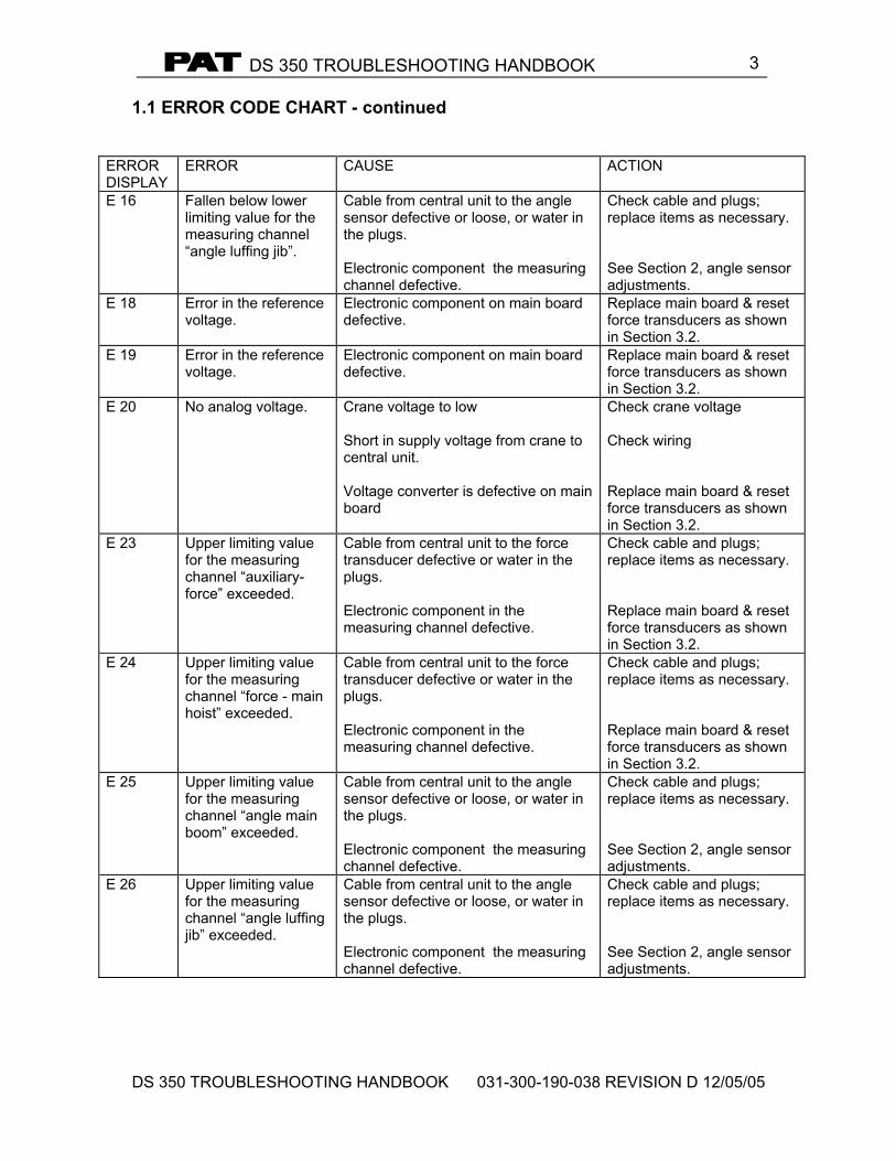
1.1 ERROR CODE CHART - continued
ERROR DISPLAY
ERROR CAUSE ACTION
E 16 Fallen below lower limiting value for the measuring channel “angle luffing jib”.
Cable from central unit to the angle sensor defective or loose, or water in the plugs. Electronic component the measuring channel defective.
Check cable and plugs; replace items as necessary. See Section 2, angle sensor adjustments.
E 18 Error in the reference voltage.
Electronic component on main board defective.
Replace main board & reset force transducers as shown in Section 3.2.
E 19 Error in the reference voltage.
Electronic component on main board defective.
Replace main board & reset force transducers as shown in Section 3.2.
E 20 No analog voltage. Crane voltage to low Short in supply voltage from crane to central unit. Voltage converter is defective on main board
Check crane voltage Check wiring Replace main board & reset force transducers as shown in Section 3.2.
E 23 Upper limiting value for the measuring channel “auxiliary-force” exceeded.
Cable from central unit to the force transducer defective or water in the plugs. Electronic component in the measuring channel defective.
Check cable and plugs; replace items as necessary. Replace main board & reset force transducers as shown in Section 3.2.
E 24 Upper limiting value for the measuring channel “force - main hoist” exceeded.
Cable from central unit to the force transducer defective or water in the plugs. Electronic component in the measuring channel defective.
Check cable and plugs; replace items as necessary. Replace main board & reset force transducers as shown in Section 3.2.
E 25 Upper limiting value for the measuring channel “angle main boom” exceeded.
Cable from central unit to the angle sensor defective or loose, or water in the plugs. Electronic component the measuring channel defective.
Check cable and plugs; replace items as necessary. See Section 2, angle sensor adjustments.
E 26 Upper limiting value for the measuring channel “angle luffing jib” exceeded.
Cable from central unit to the angle sensor defective or loose, or water in the plugs. Electronic component the measuring channel defective.
Check cable and plugs; replace items as necessary. See Section 2, angle sensor adjustments.
DS 350 TROUBLESHOOTING HANDBOOK
DS 350 TROUBLESHOOTING HANDBOOK 031-300-190-038 REVISION D 12/05/05
4
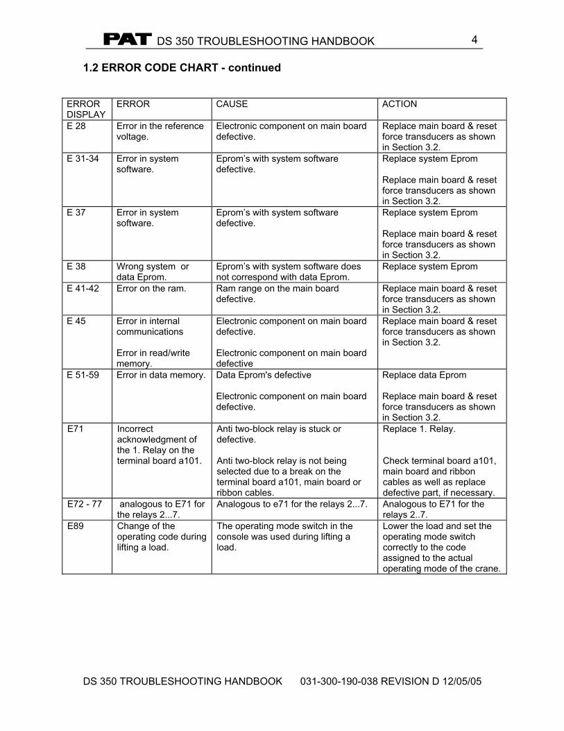
1.2 ERROR CODE CHART - continued
ERROR DISPLAY
ERROR CAUSE ACTION
E 28 Error in the reference voltage.
Electronic component on main board defective.
Replace main board & reset force transducers as shown in Section 3.2.
E 31-34 Error in system software.
Eprom’s with system software defective.
Replace system Eprom Replace main board & reset force transducers as shown in Section 3.2.
E 37 Error in system software.
Eprom’s with system software defective.
Replace system Eprom Replace main board & reset force transducers as shown in Section 3.2.
E 38 Wrong system or data Eprom.
Eprom’s with system software does not correspond with data Eprom.
Replace system Eprom
E 41-42 Error on the ram. Ram range on the main board defective.
Replace main board & reset force transducers as shown in Section 3.2.
E 45 Error in internal communications Error in read/write memory.
Electronic component on main board defective. Electronic component on main board defective
Replace main board & reset force transducers as shown in Section 3.2.
E 51-59 Error in data memory. Data Eprom's defective Electronic component on main board defective.
Replace data Eprom Replace main board & reset force transducers as shown in Section 3.2.
E71 Incorrect acknowledgment of the 1. Relay on the terminal board a101.
Anti two-block relay is stuck or defective. Anti two-block relay is not being selected due to a break on the terminal board a101, main board or ribbon cables.
Replace 1. Relay. Check terminal board a101, main board and ribbon cables as well as replace defective part, if necessary.
E72 - 77 analogous to E71 for the relays 2...7.
Analogous to e71 for the relays 2...7. Analogous to E71 for the relays 2..7.
E89 Change of the operating code during lifting a load.
The operating mode switch in the console was used during lifting a load.
Lower the load and set the operating mode switch correctly to the code assigned to the actual operating mode of the crane.
DS 350 TROUBLESHOOTING HANDBOOK
DS 350 TROUBLESHOOTING HANDBOOK 031-300-190-038 REVISION D 12/05/05
5
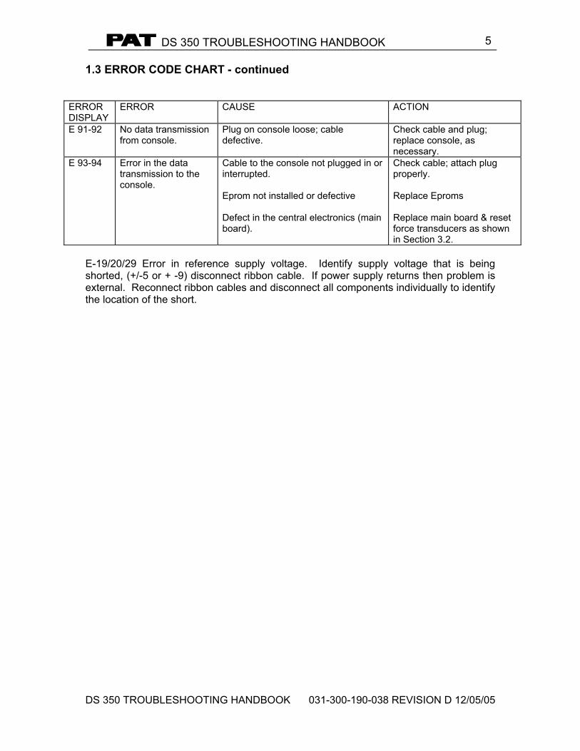
1.3 ERROR CODE CHART - continued
ERROR DISPLAY
ERROR CAUSE ACTION
E 91-92 No data transmission from console.
Plug on console loose; cable defective.
Check cable and plug; replace console, as necessary.
E 93-94 Error in the data transmission to the console.
Cable to the console not plugged in or interrupted. Eprom not installed or defective Defect in the central electronics (main board).
Check cable; attach plug properly. Replace Eproms Replace main board & reset force transducers as shown in Section 3.2.
E-19/20/29 Error in reference supply voltage. Identify supply voltage that is being shorted, (+/-5 or + -9) disconnect ribbon cable. If power supply returns then problem is external. Reconnect ribbon cables and disconnect all components individually to identify the location of the short.
DS 350 TROUBLESHOOTING HANDBOOK
DS 350 TROUBLESHOOTING HANDBOOK 031-300-190-038 REVISION D 12/05/05
6
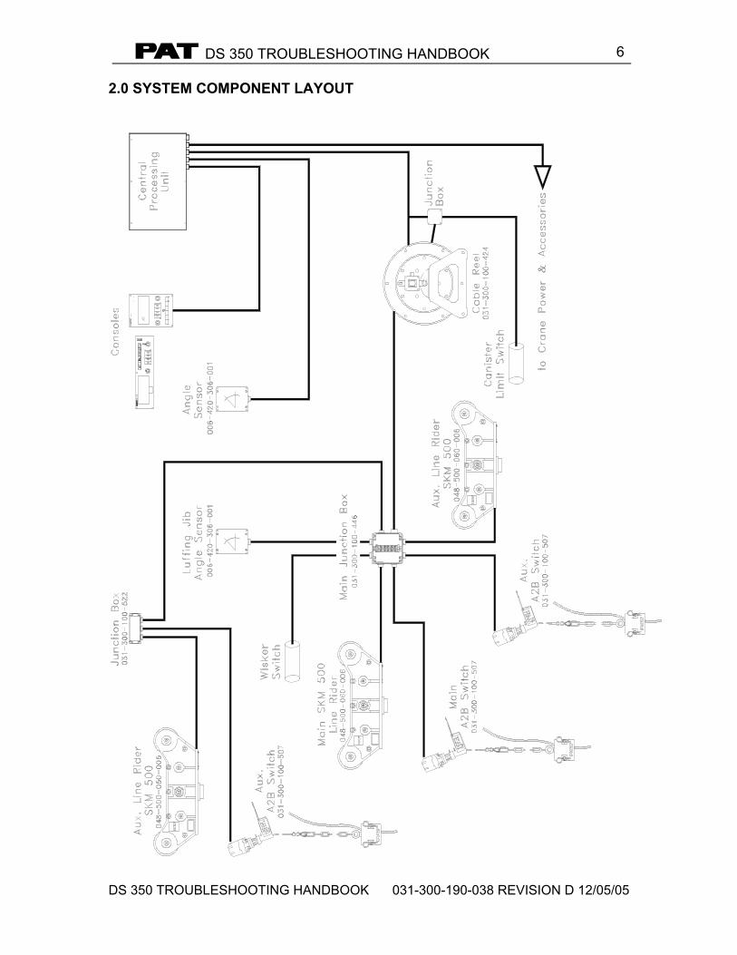
2.0 SYSTEM COMPONENT LAYOUT
DS 350 TROUBLESHOOTING HANDBOOK
DS 350 TROUBLESHOOTING HANDBOOK 031-300-190-038 REVISION D 12/05/05
73.0 ANGLE SENSOR ADJUSTMENT
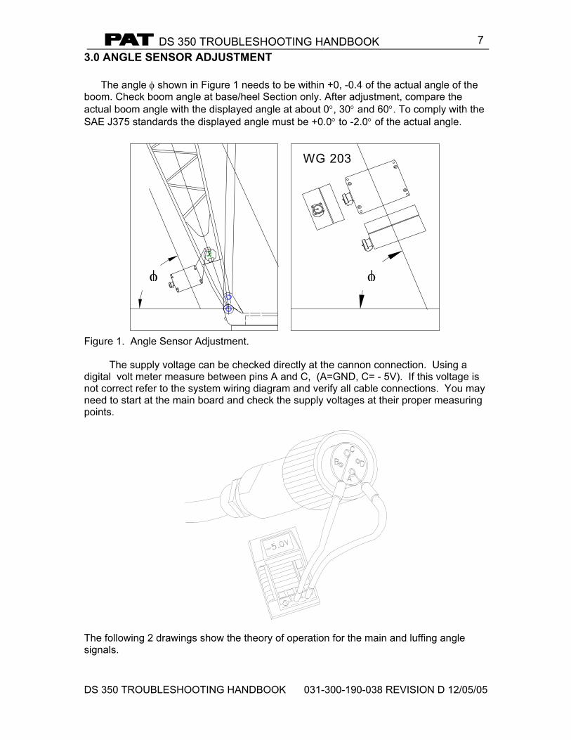
The angle φ shown in Figure 1 needs to be within +0, -0.4 of the actual angle of the boom. Check boom angle at base/heel Section only. After adjustment, compare the actual boom angle with the displayed angle at about 0°, 30° and 60°. To comply with the SAE J375 standards the displayed angle must be +0.0° to -2.0° of the actual angle.
WG 203
φ φ
Figure 1. Angle Sensor Adjustment.
The supply voltage can be checked directly at the cannon connection. Using a
digital volt meter measure between pins A and C, (A=GND, C= - 5V). If this voltage is not correct refer to the system wiring diagram and verify all cable connections. You may need to start at the main board and check the supply voltages at their proper measuring points.
The following 2 drawings show the theory of operation for the main and luffing angle signals.
DS 350 TROUBLESHOOTING HANDBOOK
DS 350 TROUBLESHOOTING HANDBOOK 031-300-190-038 REVISION D 12/05/05
8
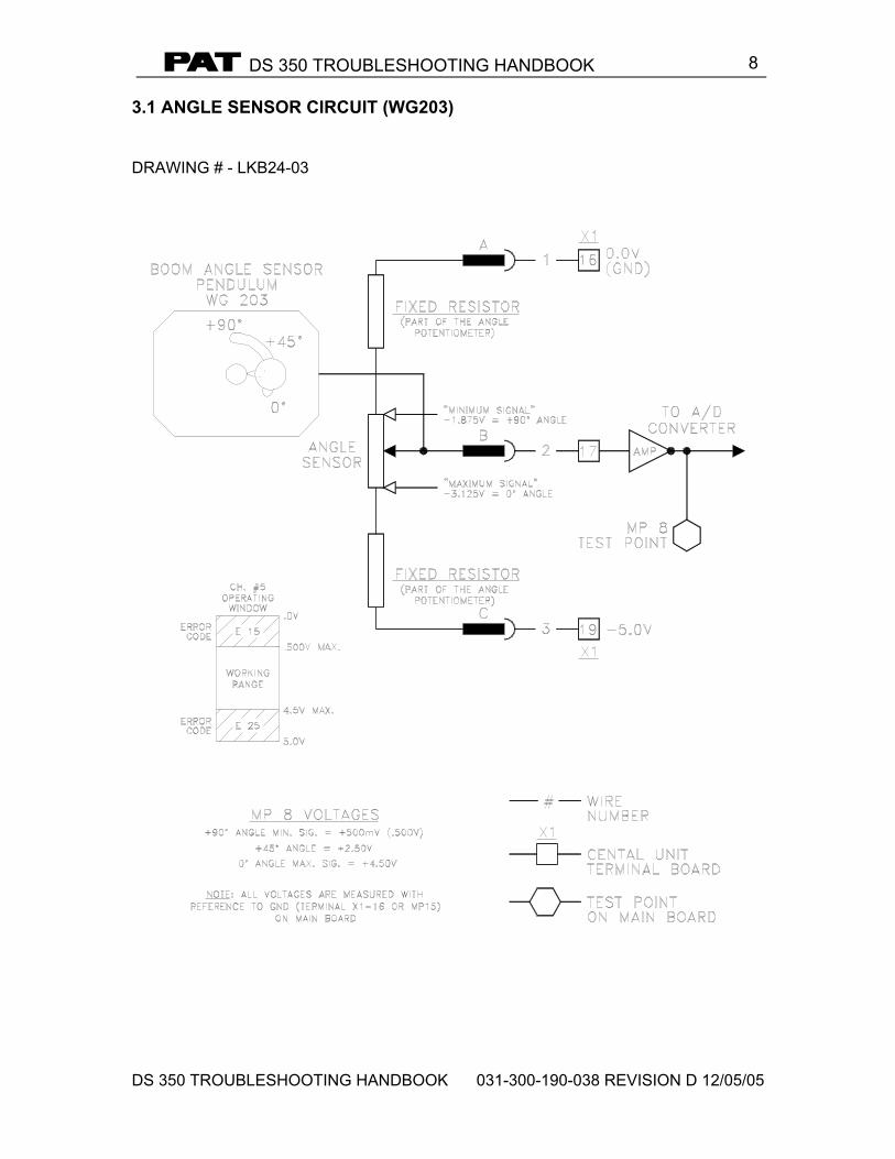
3.1 ANGLE SENSOR CIRCUIT (WG203) DRAWING # - LKB24-03
DS 350 TROUBLESHOOTING HANDBOOK
DS 350 TROUBLESHOOTING HANDBOOK 031-300-190-038 REVISION D 12/05/05
9
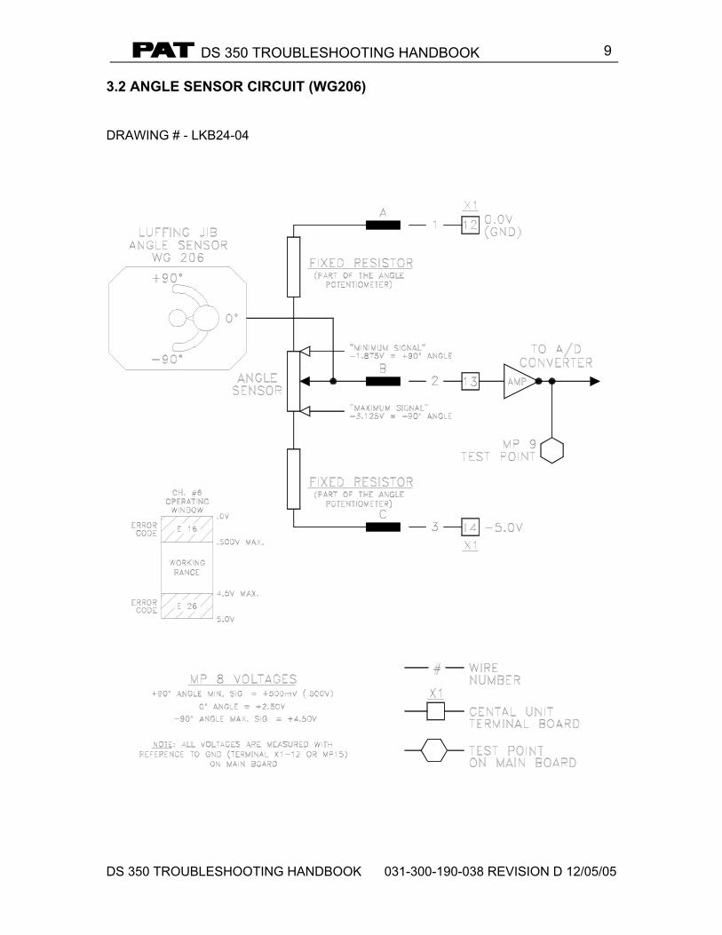
3.2 ANGLE SENSOR CIRCUIT (WG206) DRAWING # - LKB24-04
DS 350 TROUBLESHOOTING HANDBOOK
DS 350 TROUBLESHOOTING HANDBOOK 031-300-190-038 REVISION D 12/05/05
10
4.0 LINERIDER SETTINGS AND ADJUSTMENTS
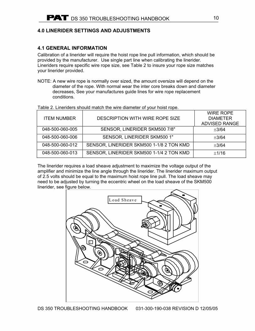
4.1 GENERAL INFORMATION Calibration of a linerider will require the hoist rope line pull information, which should be provided by the manufacturer. Use single part line when calibrating the linerider. Lineriders require specific wire rope size, see Table 2 to insure your rope size matches your linerider provided. NOTE: A new wire rope is normally over sized, the amount oversize will depend on the
diameter of the rope. With normal wear the inter core breaks down and diameter decreases, See your manufactures guide lines for wire rope replacement conditions.
Table 2. Lineriders should match the wire diameter of your hoist rope.
ITEM NUMBER
DESCRIPTION WITH WIRE ROPE SIZE
WIRE ROPE DIAMETER
ADVISED RANGE 048-500-060-005 SENSOR, LINERIDER SKM500 7/8" ±3/64 048-500-060-006 SENSOR, LINERIDER SKM500 1" ±3/64 048-500-060-012 SENSOR, LINERIDER SKM500 1-1/8 2 TON KMD ±3/64 048-500-060-013 SENSOR, LINERIDER SKM500 1-1/4 2 TON KMD ±1/16
The linerider requires a load sheave adjustment to maximize the voltage output of the amplifier and minimize the line angle through the linerider. The linerider maximum output of 2.5 volts should be equal to the maximum hoist rope line pull. The load sheave may need to be adjusted by turning the eccentric wheel on the load sheave of the SKM500 linerider, see figure below.
P
L o ad S h eav e
DS 350 TROUBLESHOOTING HANDBOOK
DS 350 TROUBLESHOOTING HANDBOOK 031-300-190-038 REVISION D 12/05/05
11
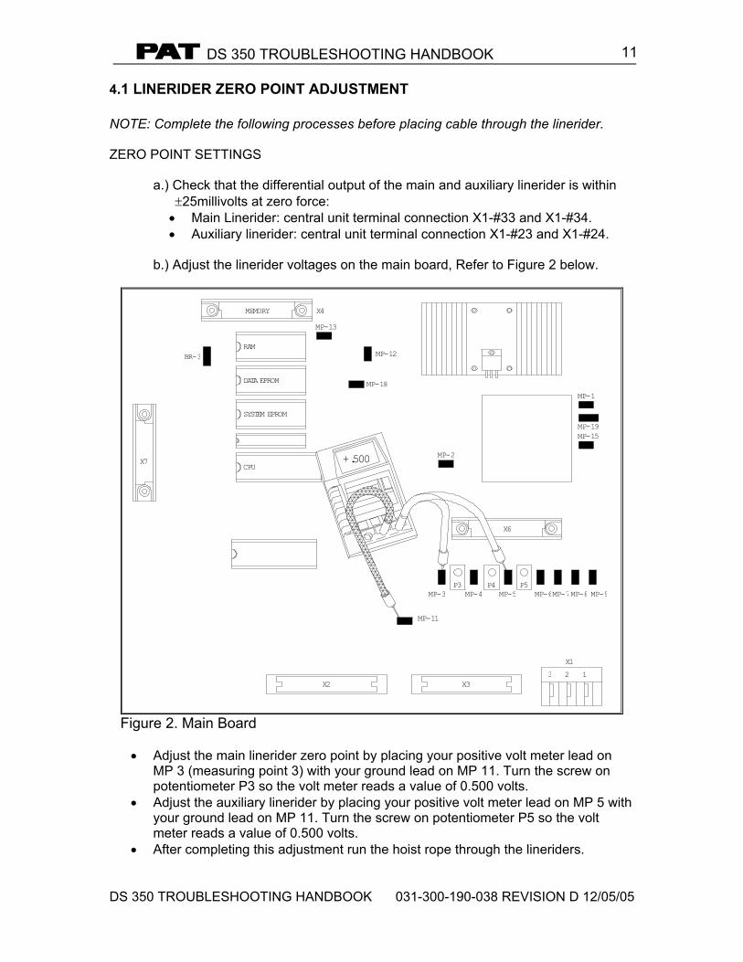
4.1 LINERIDER ZERO POINT ADJUSTMENT NOTE: Complete the following processes before placing cable through the linerider. ZERO POINT SETTINGS
a.) Check that the differential output of the main and auxiliary linerider is within ±25millivolts at zero force: • Main Linerider: central unit terminal connection X1-#33 and X1-#34. • Auxiliary linerider: central unit terminal connection X1-#23 and X1-#24.
b.) Adjust the linerider voltages on the main board, Refer to Figure 2 below.
SYSTEM EPROM
CPUX7
BR-3
DATA EPROM
MEMORY
RAM
X2
MP-11
X3
P3MP-3 MP-4
MP-18
MP-12
+.500
X4
MP-13
MP-2
X1
P5P4MP-5
3 2
MP-6MP-7
X6
1
MP-9MP-8
MP-15MP-19
MP-1
Figure 2. Main Board
• Adjust the main linerider zero point by placing your positive volt meter lead on
MP 3 (measuring point 3) with your ground lead on MP 11. Turn the screw on potentiometer P3 so the volt meter reads a value of 0.500 volts.
• Adjust the auxiliary linerider by placing your positive volt meter lead on MP 5 with your ground lead on MP 11. Turn the screw on potentiometer P5 so the volt meter reads a value of 0.500 volts.
• After completing this adjustment run the hoist rope through the lineriders.
DS 350 TROUBLESHOOTING HANDBOOK
DS 350 TROUBLESHOOTING HANDBOOK 031-300-190-038 REVISION D 12/05/05
12
4.2 LINERIDER OUTPUT ADJUSTMENT LINERIDER OUTPUT ADJUSTMENTS
a) Calculate the output voltage required from the linerider using the known the
total load and maximum line pull information. The tolerance for the output voltage “X” is +0.0, -0.2 volts.
NOTE: The total load includes the load, rigging, cables, and hook block. Test
load should be 80% of maximum rated load for the cranes configuration or condition. To comply with the SAE J376 standards the test load must be to a known accuracy of ±1%.
TEST LOAD x 2.5 = ÷ PARTS OF LINE = X LINE PULL 23.600 x 2.5 = 2.0 ÷ 1 = 2.0 29.500 “X” is equal to the to optimum output voltage of the linerider. The output voltage required in this example is 1.8 to 2.0 volts.
WARNING: THE OPERATOR IS RESPONSIBLE FOR OPERATING THE CRANE
WITHIN THE MANUFACTURE’S SPECIFIED PARAMETERS.
b) Pick the test load used in the calculation for the output voltage with a single part of line.
c) Take a voltage reading with a voltmeter and compare the reading with the
calculated voltage and decide if a mechanical adjustment of the linerider is needed.
• Main Linerider: central unit terminal connection X1-#33 and X1-#34. • Auxiliary linerider: central unit terminal connection X1-#23 and X1-#24.
d) If a mechanical adjustment is necessary follow steps below, if no mechanical
adjustment is necessary proceed to next Section and begin calibration. • Before and after you set the mechanical adjustment, scribe a line on the
side of the eccentric wheel to show the amount of change. • Loosen the adjustment nut, see Figure 3. Note that there is a single lockout
nut on one side and a double on the other. These both should be loosened to some degree. Adjustment from the double nut side seems to work the best after tightening the 2 nuts together.
• Depending upon the output voltage you can look at the eccentric nut from the side of the linerider and determine the direction you should turn. Increasing the height of the load sheave will increase the output voltage.
• Tighten all lock nuts insuring not to move the wheel. e) Return and repeat step ‘c’.
DS 350 TROUBLESHOOTING HANDBOOK
DS 350 TROUBLESHOOTING HANDBOOK 031-300-190-038 REVISION D 12/05/05
13
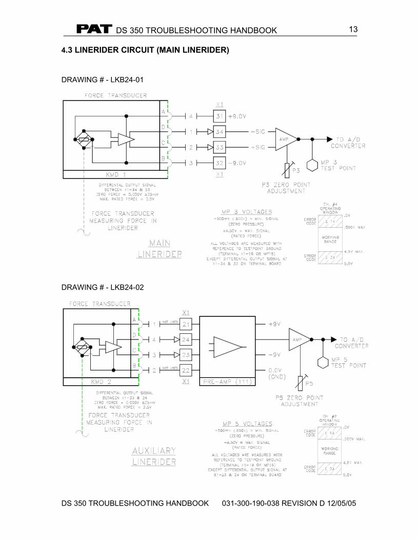
4.3 LINERIDER CIRCUIT (MAIN LINERIDER) DRAWING # - LKB24-01
DRAWING # - LKB24-02
DS 350 TROUBLESHOOTING HANDBOOK
DS 350 TROUBLESHOOTING HANDBOOK 031-300-190-038 REVISION D 12/05/05
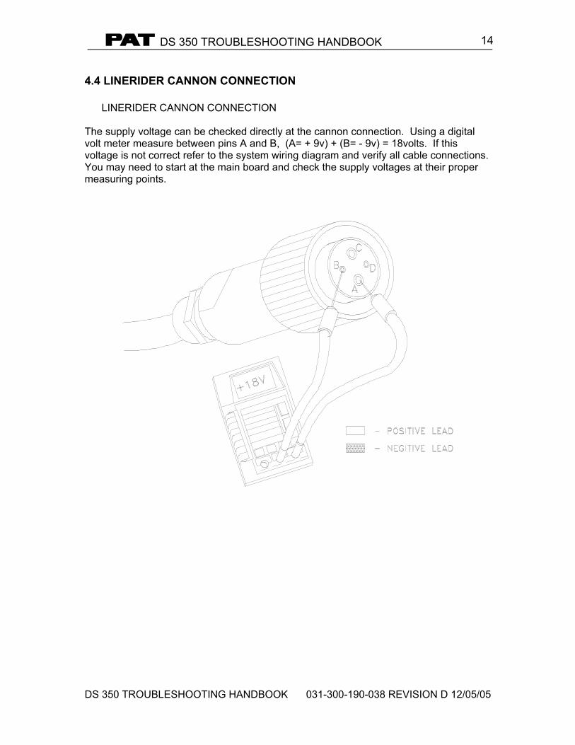
14
4.4 LINERIDER CANNON CONNECTION LINERIDER CANNON CONNECTION The supply voltage can be checked directly at the cannon connection. Using a digital volt meter measure between pins A and B, (A= + 9v) + (B= - 9v) = 18volts. If this voltage is not correct refer to the system wiring diagram and verify all cable connections. You may need to start at the main board and check the supply voltages at their proper measuring points.
DS 350 TROUBLESHOOTING HANDBOOK
DS 350 TROUBLESHOOTING HANDBOOK 031-300-190-038 REVISION D 12/05/05
15
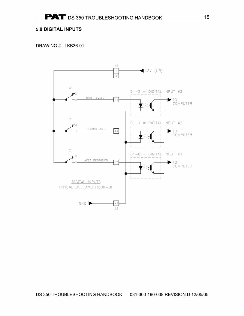
5.0 DIGITAL INPUTS DRAWING # - LKB36-01
DS 350 TROUBLESHOOTING HANDBOOK
DS 350 TROUBLESHOOTING HANDBOOK 031-300-190-038 REVISION D 12/05/05
16
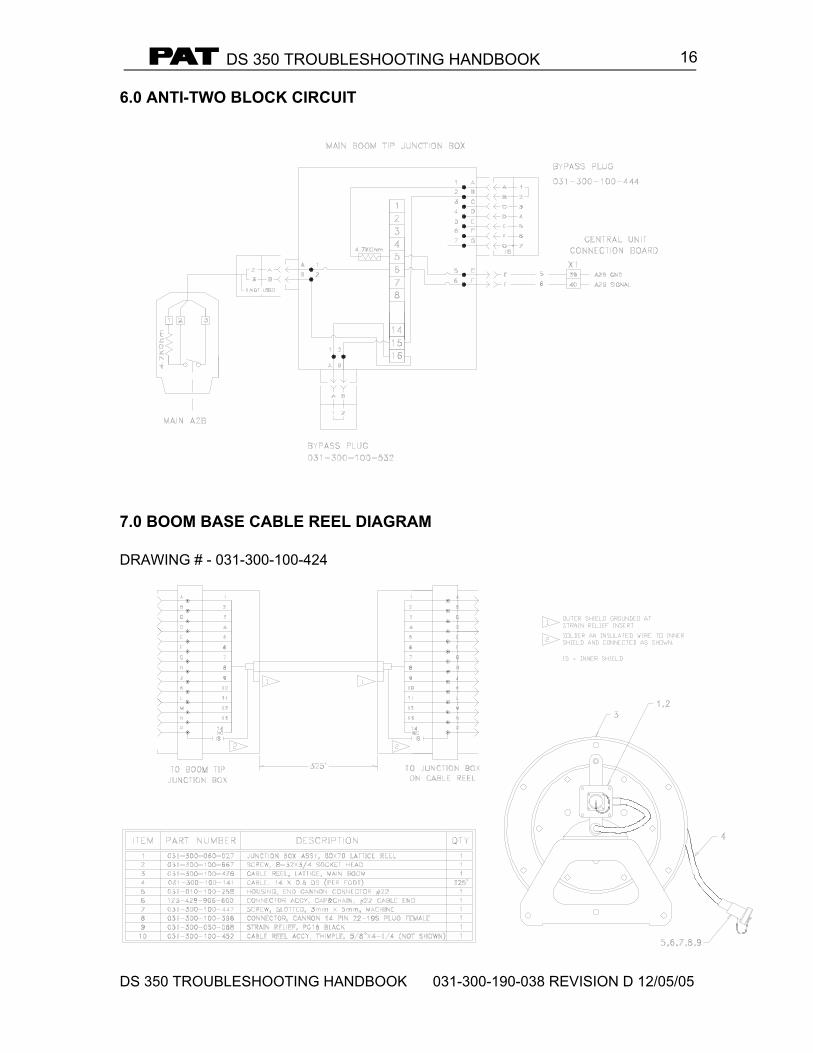
6.0 ANTI-TWO BLOCK CIRCUIT
7.0 BOOM BASE CABLE REEL DIAGRAM DRAWING # - 031-300-100-424
DS 350 TROUBLESHOOTING HANDBOOK
DS 350 TROUBLESHOOTING HANDBOOK 031-300-190-038 REVISION D 12/05/05
17
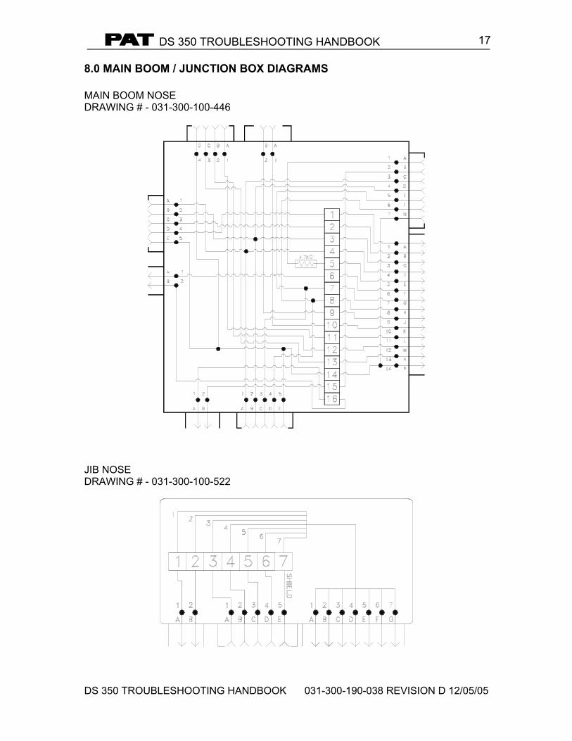
8.0 MAIN BOOM / JUNCTION BOX DIAGRAMS MAIN BOOM NOSE DRAWING # - 031-300-100-446
JIB NOSE DRAWING # - 031-300-100-522
DS 350 TROUBLESHOOTING HANDBOOK
DS 350 TROUBLESHOOTING HANDBOOK 031-300-190-038 REVISION D 12/05/05
18
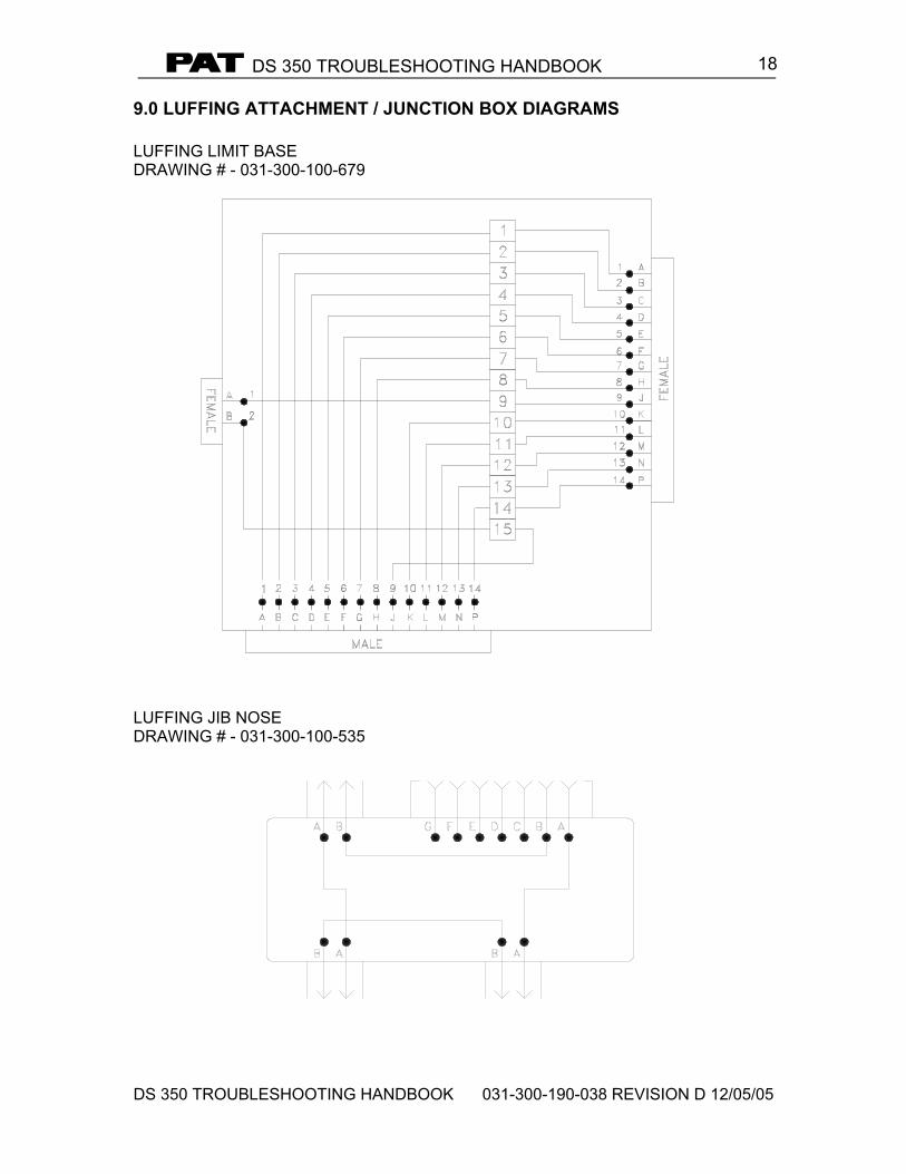
9.0 LUFFING ATTACHMENT / JUNCTION BOX DIAGRAMS LUFFING LIMIT BASE DRAWING # - 031-300-100-679
LUFFING JIB NOSE DRAWING # - 031-300-100-535
DS 350 TROUBLESHOOTING HANDBOOK
DS 350 TROUBLESHOOTING HANDBOOK 031-300-190-038 REVISION D 12/05/05
19
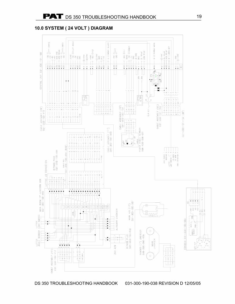
10.0 SYSTEM ( 24 VOLT ) DIAGRAM
DS 350 TROUBLESHOOTING HANDBOOK
DS 350 TROUBLESHOOTING HANDBOOK 031-300-190-038 REVISION D 12/05/05
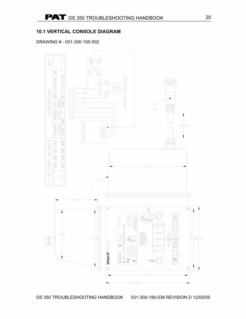
20 10.1 VERTICAL CONSOLE DIAGRAM DRAWING # - 031-300-100-502
DS 350 TROUBLESHOOTING HANDBOOK
DS 350 TROUBLESHOOTING HANDBOOK 031-300-190-038 REVISION D 12/05/05
21
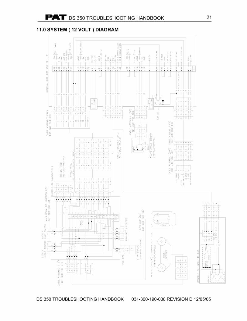
11.0 SYSTEM ( 12 VOLT ) DIAGRAM
DS 350 TROUBLESHOOTING HANDBOOK
DS 350 TROUBLESHOOTING HANDBOOK 031-300-190-038 REVISION D 12/05/05
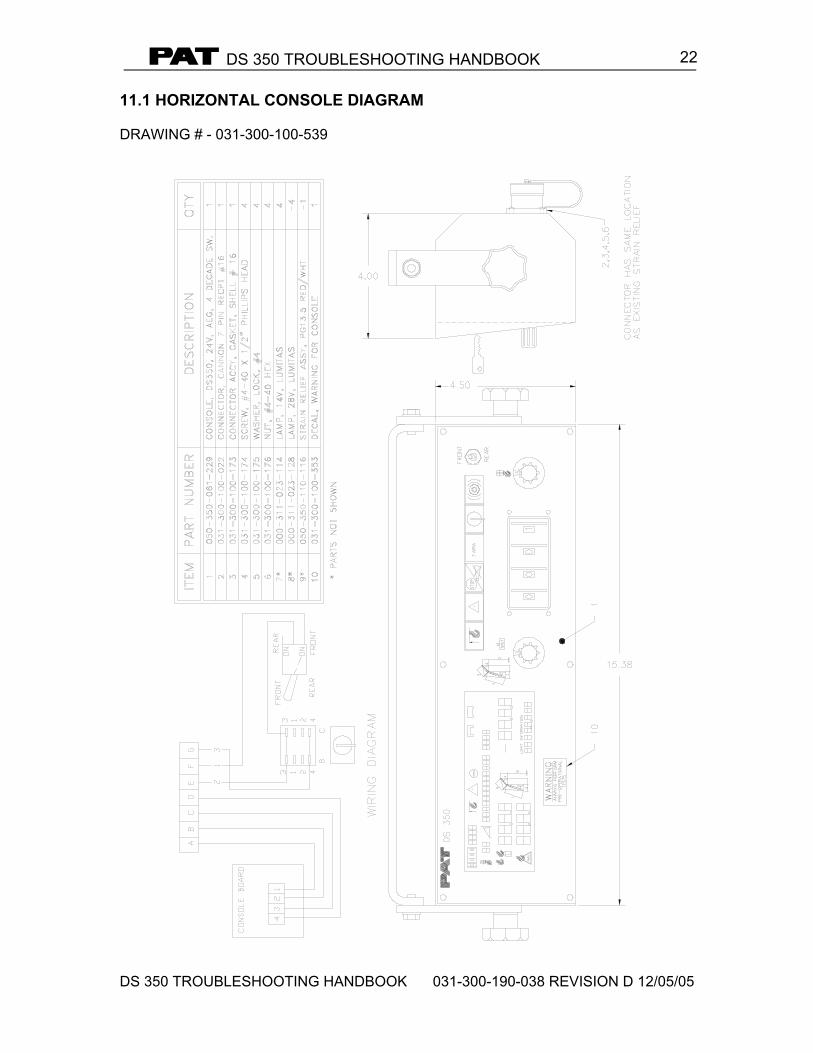
22 11.1 HORIZONTAL CONSOLE DIAGRAM DRAWING # - 031-300-100-539
DS 350 TROUBLESHOOTING HANDBOOK
DS 350 TROUBLESHOOTING HANDBOOK 031-300-190-038 REVISION D 12/05/05
23
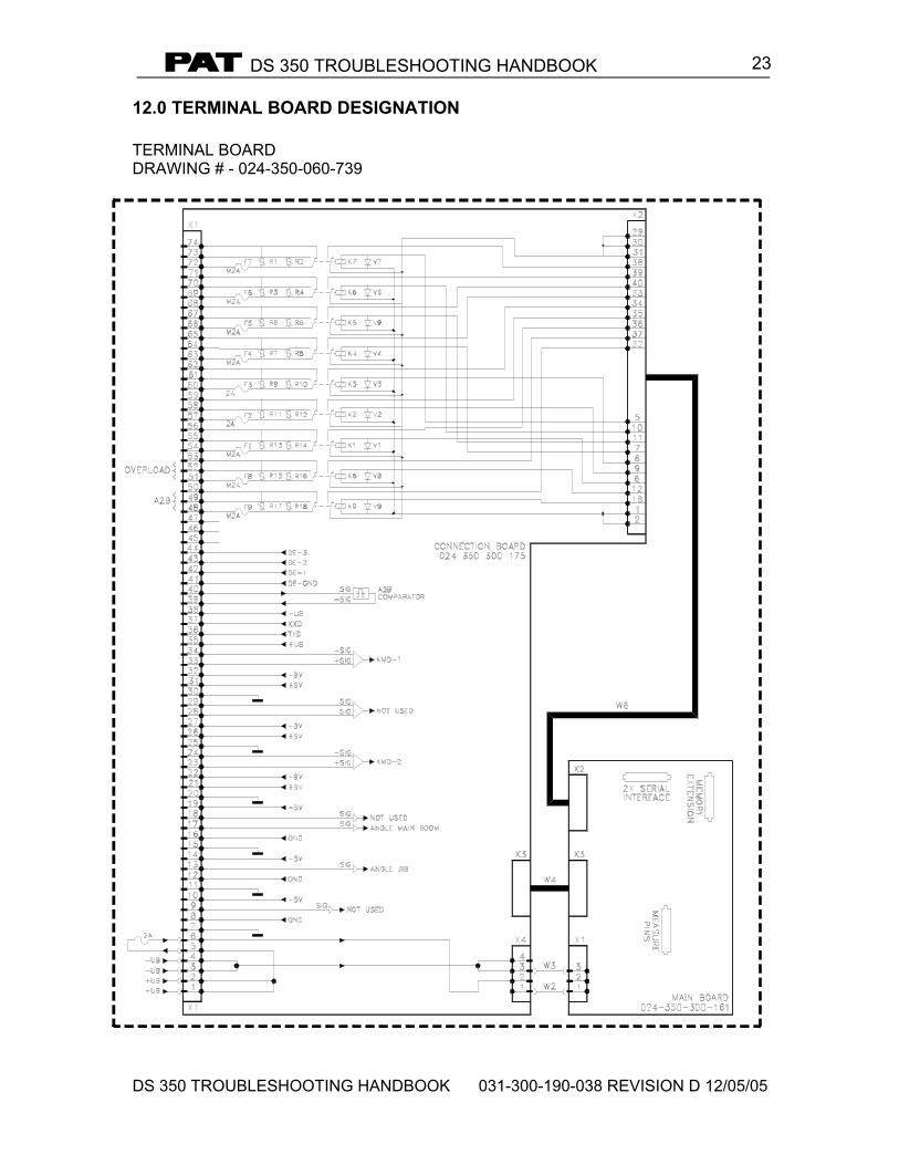
12.0 TERMINAL BOARD DESIGNATION TERMINAL BOARD DRAWING # - 024-350-060-739
DS 350 TROUBLESHOOTING HANDBOOK
DS 350 TROUBLESHOOTING HANDBOOK 031-300-190-038 REVISION D 12/05/05
24
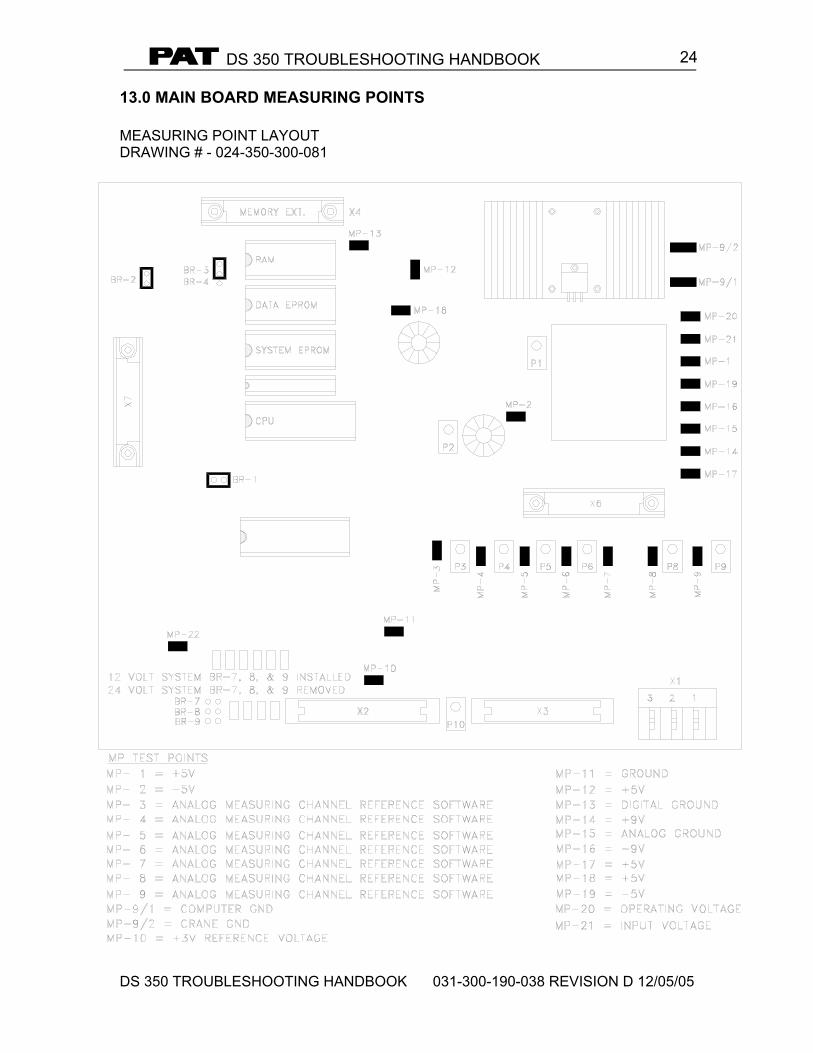
13.0 MAIN BOARD MEASURING POINTS MEASURING POINT LAYOUT DRAWING # - 024-350-300-081